1. Introduction to Thermal Spray Processes
Thermal spraying is a general term to describe all methods in which the coating is formed from melted or semi-melted droplets. In thermal spraying the material is in the form of powder, wire or rod and is fed into the flame produced by a spray gun, where it melts and the formed droplets are accelerated towards the substrate to be coated. The thermal and kinetic energy of the flame can be produced either with burning mixtures of fuel gas and oxygen, or by using an electrical power source. Based on the energy source, thermal spray methods can be divided into a few main groups: plasma spray methods (atmospheric plasma APS, vacuum plasma VPS, and low pressure plasma LPPS), combustion flame spray methods (flame spray), high velocity oxy/air-fuel methods (HVOF/HVAF), electrical arc methods (wire arc), detonation method (D-Gun), and, as the latest technology, cold gas methods (CGS).
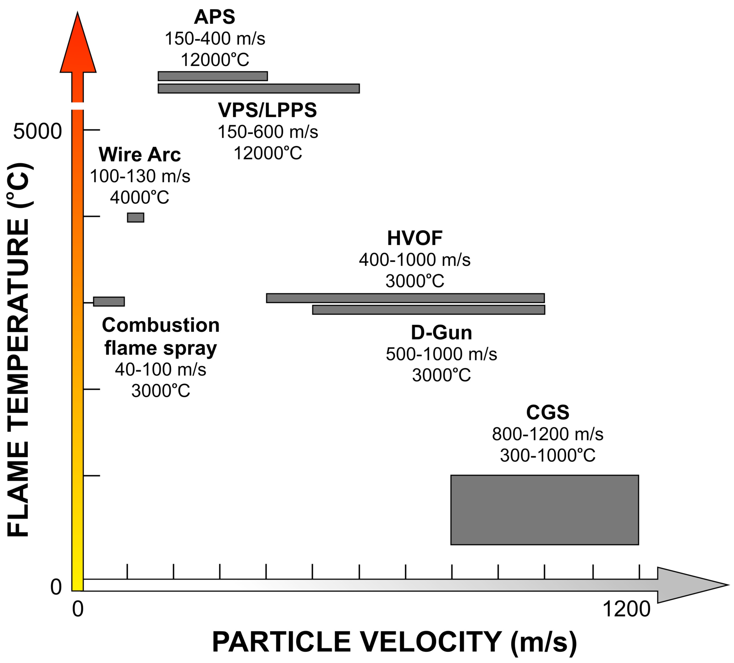
Since coating is built up from flattened, fast solidified droplets the velocity plays an important role for the obtained density of the lamella structured coating. Temperature of the flame has a strong effect on the suitable materials to be sprayed. Ceramic coatings are mainly manufactured by using atmospheric plasma spray method, while temperature sensitive materials, such as cermets, are more preferably sprayed by methods with a lower flame temperature. In
Figure 1 the typical operation ranges for various spray systems are presented.
Thermal spray coatings are often applied for better corrosion and wear resistance. Therefore, low porosity and good adhesion are desired properties for the coating. High velocity processes—especially HVOF (High velocity oxy-fuel) spraying—are the preferred methods for producing coating with low porosity and high adhesion. In HVOF spraying, heat is produced by burning mixture of oxygen and fuel such as hydrogen, kerosene, propane, propylene, natural gas, ethylene, or acetylene. Due to the special nozzle design, a jet with supersonic speed is produced.
The ability to produce dense coatings with low amount of degradation, oxidation of metallic materials, and phase transformations is the main feature of the HVOF process. This is due to the short dwell time of the particles in a relatively cold flame. It is widely used to produce cermet and metal coatings, but the HVOF process has also been demonstrated to be able to deposit dense ceramic coatings.
In the HVOF process, fuel and oxygen are introduced to the combustion chamber together with the spray powder. The combustion of the gases produces a high temperature and high pressure in the chamber, which causes the supersonic flow of the gases through the nozzle. The powder particles melt or partially melt in the combustion chamber and during the flight through the nozzle. The flame temperature varies in the range of 2500 °C–3200 °C, depending on the fuel, the fuel gas/oxygen ratio and the gas pressure. In the HVOF process the particles melt completely or only partially, depending on the flame temperature, particle dwell time, material melting point and thermal conductivity.
A few different HVOF spray systems exist with partly different gun designs and capacities. Each one has differences in design, but all are based on the same fundamental principles. The combination of high pressure (over 3 bar) and gas flow rates of several hundred liters per minute generate supersonic gas velocities. These systems can be roughly divided into the first, second and third generation. In all first and second generation guns, the pressurized burning of gaseous fuel with oxygen is used to produce an exhaust jet traveling at a speed of about 2000 m/s. The main fundamental difference between first and second generation is the design of the nozzle. In the first generation HVOF systems there is typically relatively large combustion chamber and a straight nozzle. With this design maximum of 1 Mach (gas velocity related to the sonic speed) velocities can be produced. The second generation is based on the de Laval nozzle, which enables over 1 Mach velocities at the diverging part of the nozzle. Under standard spray conditions the systems are operated at a power level of about 100 kW and are capable of spraying about 2–3 kg/h of WC-Co. The third generation systems are for power levels ranging from 100 to 300 kW and for higher chamber pressures ranging from 8 bar up to as far as 25 bars, being capable of spray rates up to about 10 kg/h.
Table 1 summarizes the key differences between generations.
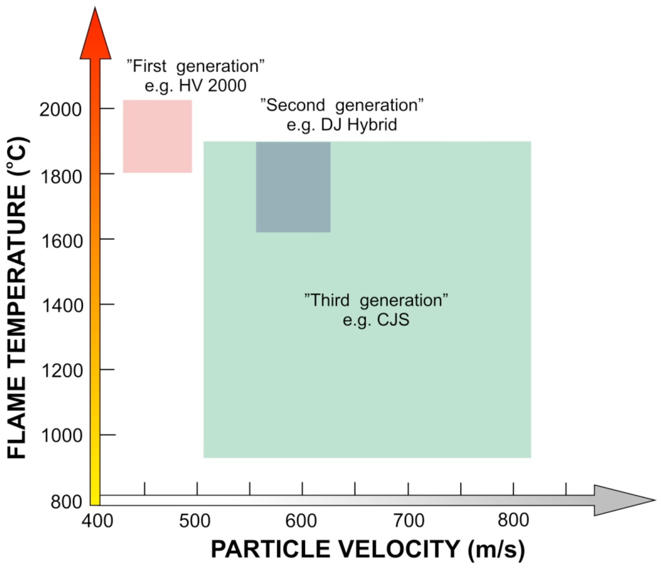
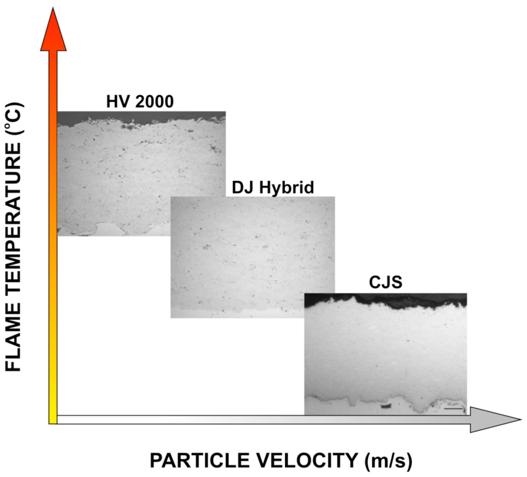
From a scientific point of view, particle velocity (v) and particle temperature (T) together with substrate characteristics are the main parameters affecting the deposit formation. They determine the deposit build-up process and deposit properties. Particle velocity and temperature affect the deposit efficiency as well as the microstructure. Trend in HVOF process development has been towards higher gas pressures, faster particle velocities and lower particle temperatures as shown schematically in
Figure 2. This has a clear influence on the coating microstructure, where amount of oxidation in the lamella boundary is decreased and flattening rate is increased, and due to this the coating density is improved generation by generation, as presented in the
Figure 3.
2. HVOF Process Optimization
HVOF spraying is a very complex process, which has a large variety of variables affecting the deposit formation and hence coating properties. These variables include hardware characteristics (e.g., nozzle geometry and spraying distance) and process parameters, e.g., fuel gas, gas flow density, and powder feedstock. In the spray process, the powder particles experience very high speed combined with fast heating up to its melting point or above. This high temperature may cause evaporation of the powder or some components of it, dissolution, and phase transformations. Due to this complex nature of HVOF technique, the control and optimization of the process in order to achieve coating with desired properties is a highly challenging task. There are different ways of optimizing and analyzing the thermal spray processes and deposit formation. These include statistical methods such as Taguchi and design of experiments (DoE), numerical modeling and simulation, and FE methodology [
1-
5]. In the Taguchi method, for example, the test matrix can be significantly reduced and the relative importance between variables can be determined sufficiently. The result in Taguchi is dependent on the design and selection of variables and their levels and the result may therefore be misleading. Determining the importance and weight of a large number of variables is very difficult with the HVOF process. This applies to different modeling procedures as well.
Good coating quality with suitable properties and required performance for specific applications is the goal in producing thermal spray coatings. In order to reach this goal, a deeper understanding of the spray process as a whole is needed. Starting material, spray process and particle-substrate interactions all affect the formation of coating with different microstructure and hence the coating properties and eventually the coating performance. Use of submicron and nanostructured powders sets demands for the coating process in order to maintain the fine-scaled structures and enhance the coating properties. For better control of thermal spraying, different sensing devices have been developed during the last decade. These diagnostic tools have enabled better investigation and measuring of the spray process, and helped to understand the impact of different process variables on in-flight particle state (flux, temperature and velocity). In tandem with the diagnostic tool development, a novel comprehensive optimization tool has been developed for thermal spray processes. The process mapping concept was first introduced by Professor Sanjay Sampath [
6], and its use has increased since introduction [
7-
10]. In this chapter the diagnostic equipments are introduced, as well as the process mapping tool and factors related to it. Examples of applying the process maps for process control and coating design are presented.
2.2. Process Optimization Procedures
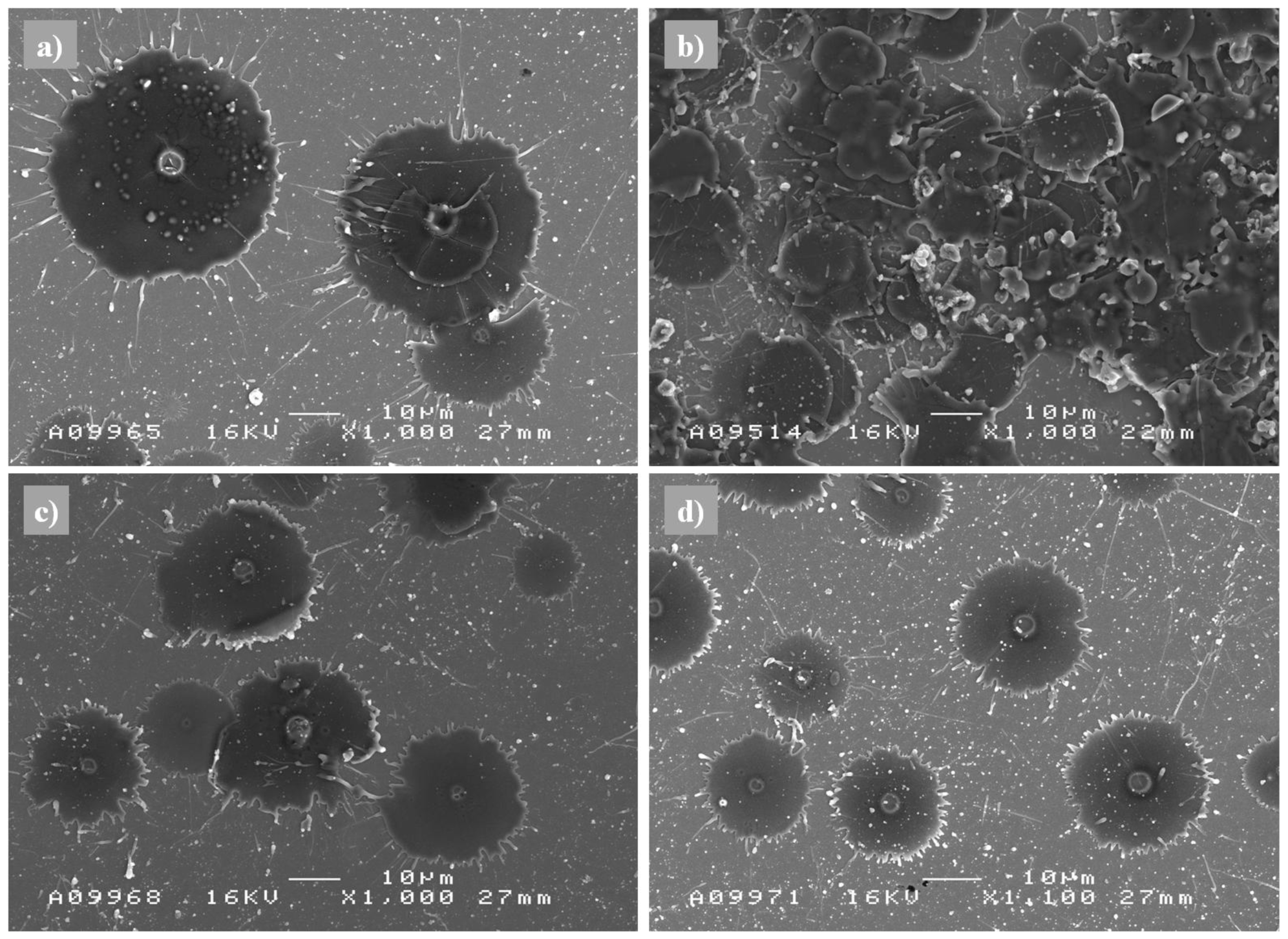
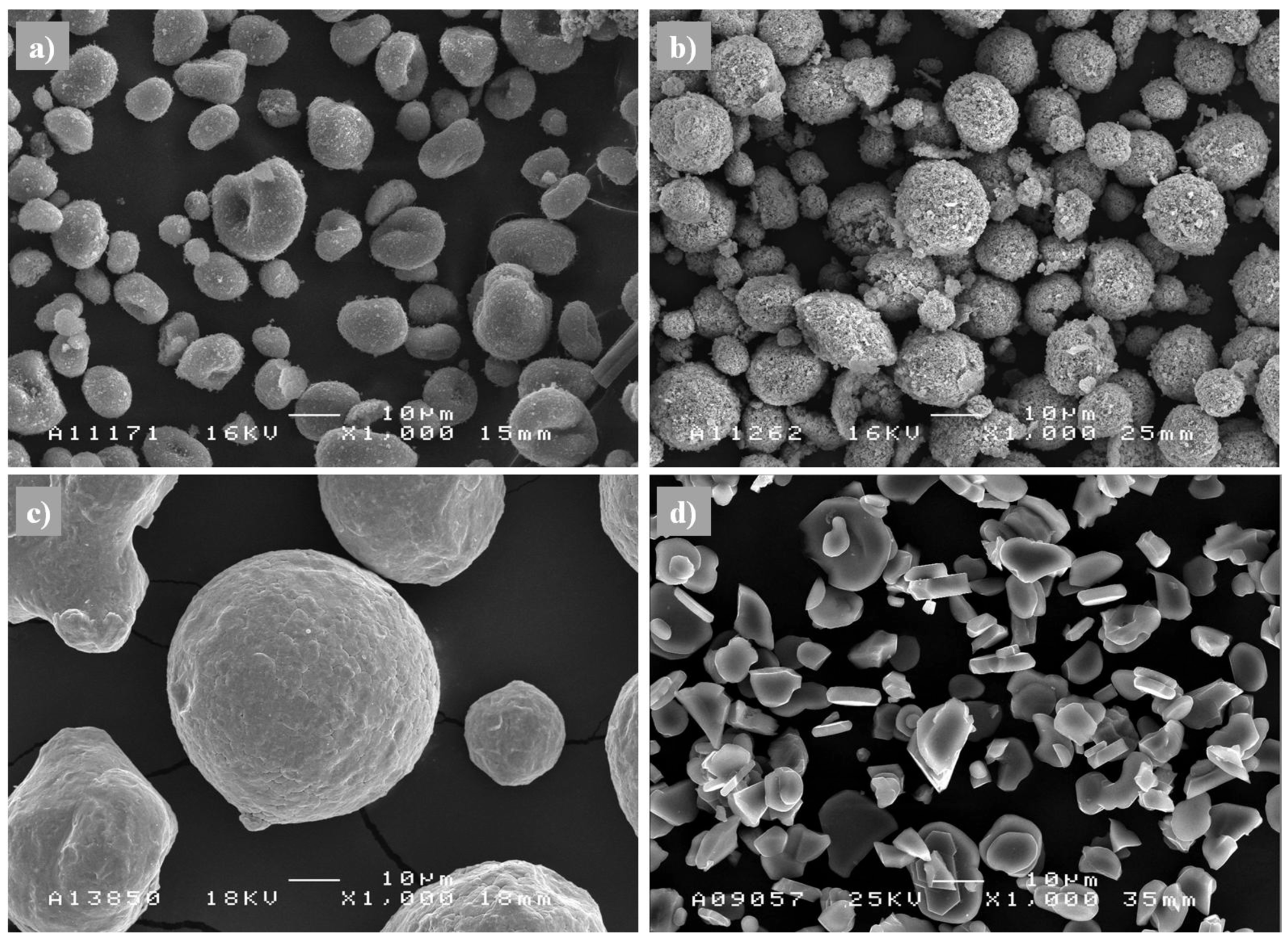
The spraying process is monitored with diagnostic sensors, which measure the particle surface temperature and velocity in the spray stream. It is very important to place the equipment correctly in-line with the spray stream. By controlling the gas flow, the fuel/oxygen ratio, or back-pressure of the chamber, different particle states are formed. In order to examine coating formation in detail, individual splats can be sprayed in parallel with using diagnostic tools. By splat studies on the polished substrate, the particle melting state can be analyzed, and hence it is possible to get more information of the diverse coating build-up process. With splat analysis, it has been shown e.g., that small NiCr particles suffer more oxidation when particle temperatures are high [
10]. It is common that high speed particles form air pockets when deposited on the substrate, especially when particles are not fully melted. Fully molten NiCr particles have formed smaller grain sized splats compared to feedstock material [
10]. Examples of splats of Al
2O
3 are presented in
Figure 4, showing different melting states of sprayed particles resulting from different spray parameters. Characterization of the formed coating by microscopic means and testing the coating after spraying, thickness, porosity, lamellar structure with fully or partially molten particles, flattening ratio, oxidation level, bonding, hardness, elastic modulus
etc. are revealed, and can be linked to process variables. When the linkages between process variables, coating microstructure and properties are done, the reverse deduction is also possible. When a certain property is the goal, it is possible to go backwards by process maps and identify the correct process parameters in order to achieve the desired property.
Three operational gas/liquid flow variables can be used for the control of HVOF process: (i) choice of used gases/liquids; (ii) total volume flow of gases/liquids; and (iii) the ratio between them (oxygen/fuel). All these have influence on particle velocity (backpressure of the chamber) and particle temperature. Independent operational parameters with HVOF can be oxygen, fuel, nitrogen and air flow. Other variables, which play an important role, include spray distance and deposition rates (combination of e.g., feed rate and robot speed). Gas flow control can be used as a tool for particle state measurements (T, v), as well as a tool for using different fuels, chamber and nozzle designs, which change the particle state significantly.
The spraying process must be calibrated, so that errors in the measurement can be prevented or estimated. Use of feedback control in the process enables this. Repeating a certain condition whilst performing the process map procedure indicates the data scatter and error, both to temperature and velocity measurement. Errors rise from input parameters (emissivity), instruments, control of gas flows and feed rate, and degradation effects of nozzle and injection wear [
8]. These may have influence on the achieved temperature-velocity values during a long process time, and therefore calculation, re-calculation and re-adjusting of spraying parameters are needed throughout the spraying process.
An example of the HVOF spraying of NiCr powder has shown the influence of oxygen-rich flame, resulting in higher temperature and lower velocity [
10]. When fuel-rich flame was used, the temperature decreased (as the flame energy decreased), and particle velocity increased. Kinetic and thermal energy transferred to the particles is dependent on the flame energy (enthalpy of the used fuel, fuel density, and ratio of fuel to oxygen). Higher energy levels of the flame yield higher kinetic and thermal energies to the particles. Increment of airflow to the flame decreases the temperature and increases the particle velocity slightly by increasing the drag force to the particles and shortening of their dwell time. Changes in fuel-oxygen mixture cause stronger effect. Feed rate plays also a role on the kinetic and thermal energy. A flame quenching effect has been observed when increasing the feed rate of NiCr powder [
10]
The oxide content of the coatings is predominantly determined by the in-flight reactions. Longer flame protects the particles from oxidation by shortening the interaction with the surroundings, and by burning the oxygen within the flame, a so-called shielding effect. Therefore the fuel-rich conditions produce metallic coatings with less oxidation [
10]. Higher particle speeds reduce particle overheating, thus preventing the oxidation and decarburization of carbides [
13]. On the other hand, higher particle temperature leads to slightly higher oxide content [
10].
2.3. Process Mapping
Particle state is influenced by fuel gas chemistry (fuel/oxygen ratio), total gas flow, and energy input, which affect the particle temperature, velocity and hence coating formation dynamics and properties. The process-structure-property relations can be presented by process maps, which can be used as design tool for coating processing. Process maps are interrelationships among the process variables and output responses [
12]. The process mapping optimization tool has been widely applied for plasma spray process [
12,
14], but it can be successfully used for HVOF process as well [
10,
15].
2.3.1. Concept of Process Mapping
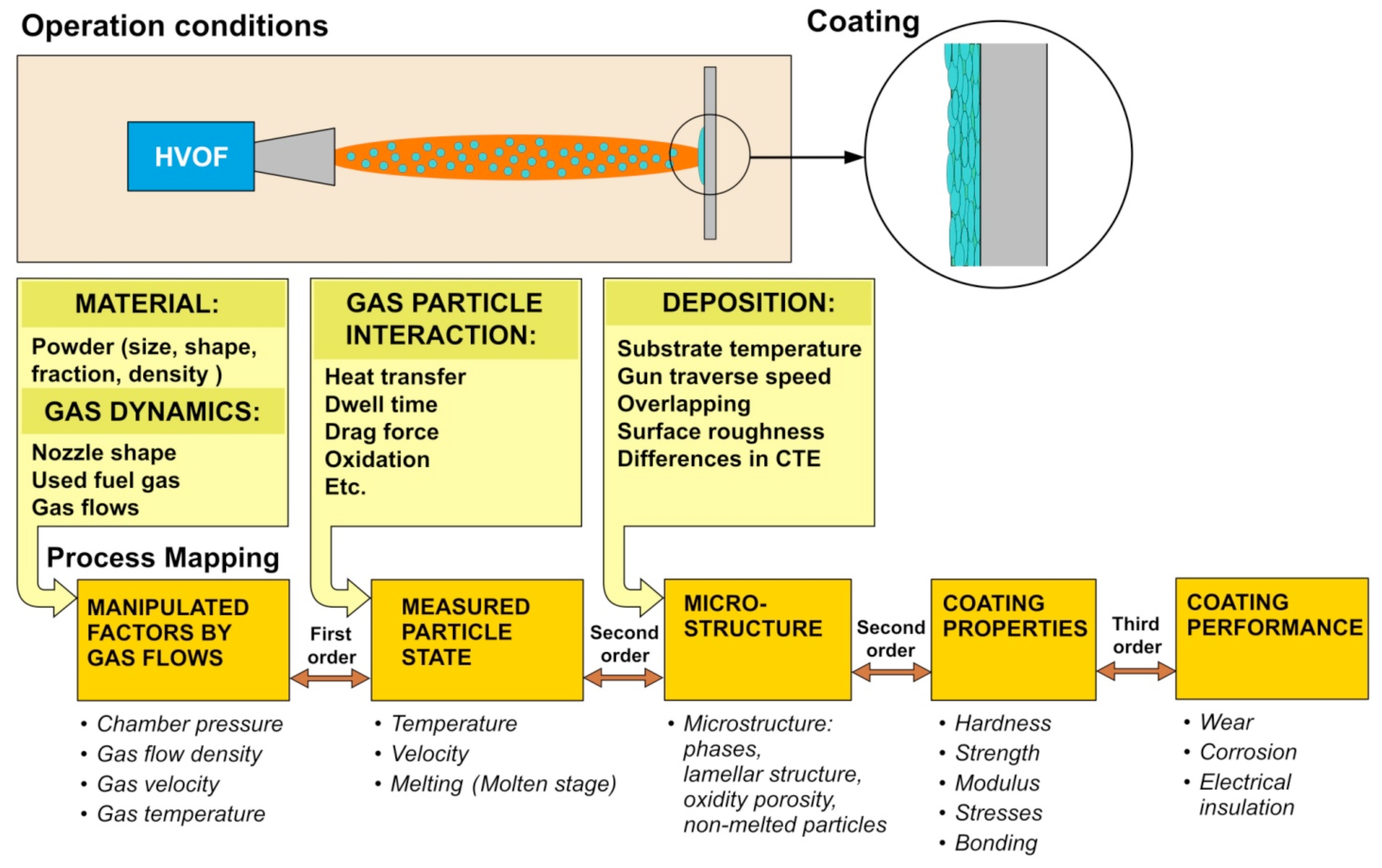
The process map methodology is developed for process control and coating properties optimization. In the process mapping concept, the diagnostic tools are used for understanding the fundamentals of relationships in the thermal spray process, starting from powder to thermal spraying process, to deposit formation, to coating characteristics, and finally to coating performance. In
Figure 5, the process map concept for HVOF spraying is presented. A first order process map expresses the relationship between torch parameters and particles in the spray stream, which are measured by diagnostics. A second order process map represents relationship between the spray stream measured responses and coating properties. Systematic evaluation of the processes, eventually leading to optimization of coating properties for specified performance and an assessment of process reliability, can be performed by creating first and second order maps for certain material and thermal spray process. A third order process map, which links coating microstructure and properties to coating performance can also be constructed.
2.3.2. First-Order Process Map
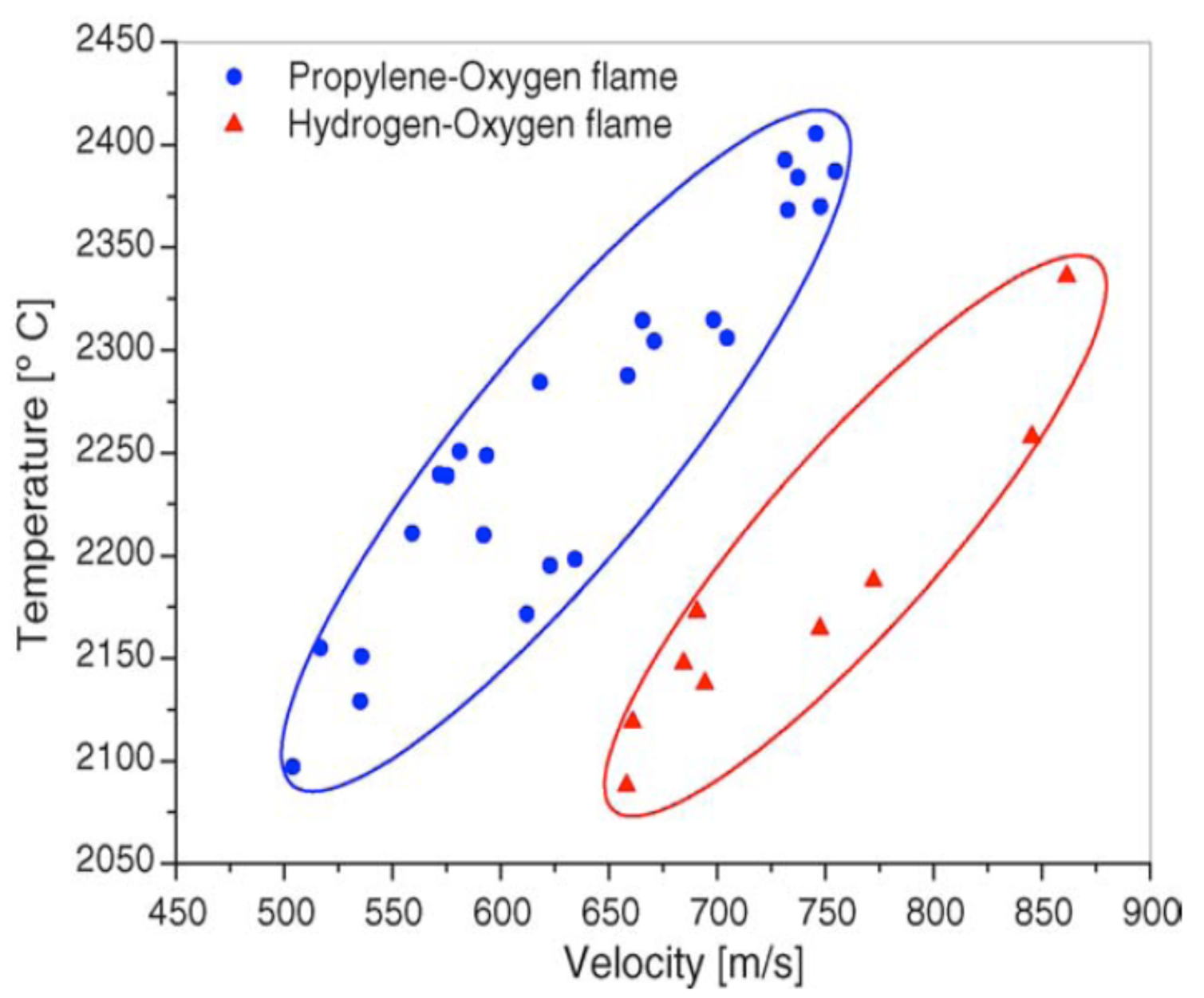
A first order process map relates the process variables to particle state (temperature and velocity). The results acquired with diagnostic tools are plotted in a T-v diagram, which is called a first order process map. An example of first-order (T-v) process map is shown in
Figure 6, which presents different temperature and velocity ranges for two different fuel mixtures for HVOF sprayed Al
2O
3 [
15]. A generalized first-order process map in
Figure 1 for different thermal spray processes, presenting the typical temperature and velocity ranges. In the figure it can be seen that HVOF process has moderate temperature and high velocity compared to other common thermal spray processes. First-order process map helps to understand how the particle state influences on the formation of the coating microstructure.
2.3.3. Second-Order Process Map
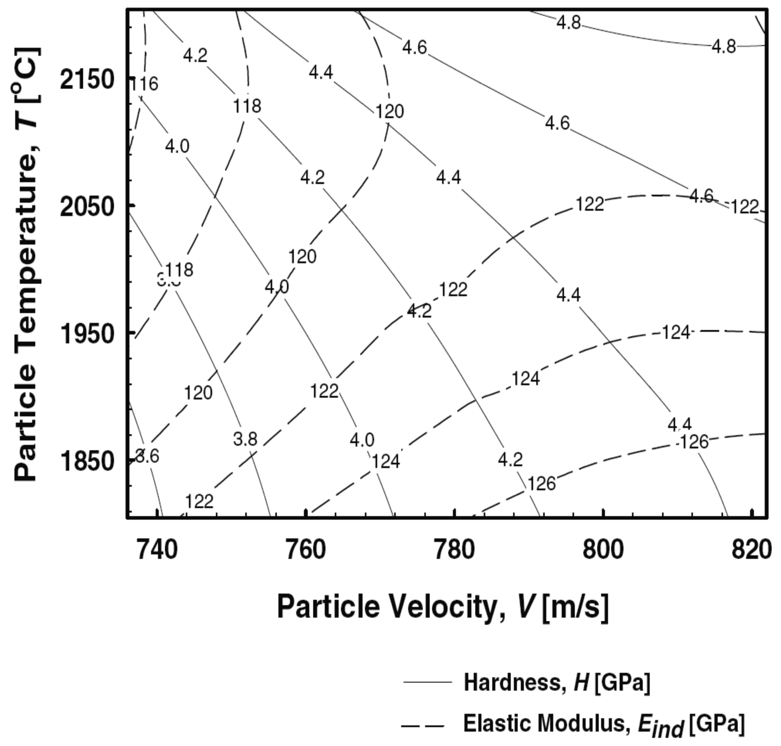
A second-order process map links the process and deposit interactions. It describes the influence of coating microstructure on the coating properties. In order to produce a second-order map, a certain T-v process window from the first-order map is selected. After the spraying, the coating properties, such as weight, elastic modulus and thermal conductivity, are measured, and thus linked to the process parameters (temperature, velocity). The purpose of the second order map is to provide a tool for designer to choose coatings of selected combination of properties and specify the values of T-v of the particle state. Actual operational parameters are specified from the first-order map. A second-order process map for HVOF sprayed NiCr is presented in
Figure 7, showing values of elastic modulus and hardness reflected with different particle temperature and velocity values [
10]. A schematic illustration of an idea of the second-order process map is presented in
Figure 3, where different HVOF processes are compared in T-v diagram, linking the formed microstructure to the process parameters.
2.4. Reliability through Process Optimization
More stringent requirements for coatings in different applications enhance the use of process optimization, repeatability, reproducibility and reliability (3 R's) of the coating process as a goal [
16]. However, reliance and manufacturing reproducibility is a complex task due to the multitude of interrelated parameters that influence spraying process and the deposit formation dynamics. The complexity of the process and material variables has made it difficult to understand the process-structure-property relationships as well as industry/application related attributes, such as coating design, property characterization and reliability [
8]. Process optimization is used for process development by parameter improvement, tracking instabilities and examining reproducibility, and that way for improved coating manufacturing. A strategy for coating design can be obtained by careful use of process maps, because process parameters can be linked to coating characteristics and hence understanding of the process-microstructure-property relationships is possible [
12]. Through process optimization it is possible to produce reliable and reproducible coatings with designed performance together with predictable life of operation [
15]. Therefore the process map concept is an excellent tool for analyzing and controlling the effects of spraying parameters in production of coatings. The method can be applied for any thermal spray technology [
10]. Also deposition efficiency (DE) can be improved, as well as process efficiency. Materials usage and the amount of defective coated components can be minimized, and that way it is possible to lower the coating production costs.
2.5. Case Studies of Process Optimization with Process Map Concept
Challenges arise when spraying nanoscale carbides, because with fine carbide sizes the dissolution of carbides and carbon loss becomes easier. The powder quality is important, as the size distribution, density, carbon and oxygen content have influence on the deposit formation. Choosing right spray process and optimizing control parameters are essential in generating good coating quality. Agglomerated and sintered WOKA 3652, −45+45 μm WC-10Co4Cr powder was sprayed with DJ Hybrid HVOF spray, with hydrogen as fuel gas. The goal was to increase both wear resistance and fracture toughness. As can be seen in the generalized second order process map for WC-CoCr in
Figure 8, a small process window to achieve such characteristics combination was found. The goal of using WC-CoCr with nanoscale carbides was to achieve high hardness combined with good fracture toughness. Thermico CJS (carbide jet spray), a colder HVOF thermal spray process with broader process window, was applied for maintaining the nanoscale carbides within the matrix. With careful process optimization, both the characteristics were enhanced [
17].
Process map methodology has been used for HVOF spraying of Ni-20%Cr coatings [
10]. Design of experiments was used to prepare a first order process map. According to the map, different conditions were chosen to produce the coatings with a low feed rate, and to analyze them with an
in-situ coating property sensor (ReliaCoat Technology ICP). It was noted that increase in the feed rate decreased both the particle temperature and velocity. In the same process optimization trials, an increment on airflow feeding was detected to result in lower particle temperature but higher velocity. When spraying distance was increased, the particle temperature was risen and the velocity was reduced. In order to enhance the thermal conductivity, high kinetic energy with high thermal energy of particles was required so as to deposit dense coatings with improved intersplat bonding (metallurgical, intimate mechanical contact), but oxide content must be kept relatively low. Electrical resistivity was enhanced with high thermal-kinetic energy as well. Stiffer coatings were formed with high particle velocity and sufficient melting state.
An example of plasma spray process optimization for yttrium stabilized zirconium (YSZ) plasma sprayed coating showed possibility of controlling the particle state within a small process window (±10 °C average temperature and ±2 m/s average velocity) by using a first order process map while varying process parameters (e.g., gas flow, current). However, different melting states were observed in the temperature distribution diagrams for various sprayings, as well as differences for deposition efficiencies, and modulus between the coatings. These results indicate that temperature and velocity measurement solely do not describe the melting state of the particles [
15].
2.6. Thermal Energy and Kinetics of Particles in Spray Stream
In order to better understand the melting behavior of particles in the spray stream, another factor has been developed besides the use of temperature. Especially with ceramic materials, with low thermal conductivity, the particle surface temperature does not directly indicate the particle melting status due to large temperature gradient within the particle [
9,
18]. The particle surface may even evaporate before the core melts. In the case of metallic materials, the oxidation of particles occurs in the spray stream. This phenomenon can have an effect on the measured temperature values and emissivity value. Melting index (MI) also takes into account the time particles stay under the influence of flame and particle size. It can be expressed as [
12]:
where T = measured particle surface temperature [K], D = particle size [m], and Δt
fly particle in-flight time assuming constant acceleration of particles [s]. In the MI formula the Δt
fly = 2L/v, where L = spray distance [m], and v = particle velocity [m/s]. MI can be defined as the ratio of particle residence time in the flame to the total time needed for particle to melt: MI = Δt
fly/Δt
melt [
9]. There is also more thorough description of melting index, which attaches thermal resistance and energy balance analysis to the formula [
9]:
where k is the thermal conductivity [W/mK], ρ is the density of the material in liquid state [kg/m ],
hf g is the enthalpy of fusion [J/kg], and
Tf is the flame temperature near the in-flight particle [K],
Tm is the melting point of the material [K],
D is the particle size [m], and Bi is the Biot number [
9].
With this approach MI is non-dimensional, which allows cross-comparison of melting state among a range of materials. From
Equation 2, it can be detected that if the flame temperature is higher than the melting point of the material, a positive MI value will be obtained, which corresponds to fully molten particles. Otherwise, the material will be unmolten (MI < 0) or partially molten (0 ≤ MI < 1). Since it is difficult to monitor the real time flame temperature in the vicinity of the flying particles, for simplifications particle surface temperature, T, has been often used instead of
Tf. Metallic particles oxidize during the spraying process, which has effect on the measured temperature by diagnostic sensors. Oxidation reactions are exothermic, which raises the particle temperature in-flight. Extent of oxidation taking place with the metallic particles is described by Oxidation index (OI) [
9].
Like temperature, the velocity values alone do not give sufficient information of the particles impinging on the substrate material and hence the deposit build-up process. Therefore either kinetic energy (KE) or Reynolds number (Re) can be used for describing the kinetic behavior of the particles. Kinetic energy is related to particle mass (m) and velocity (v) [
9]:
Reynolds number can be described with factors such as particle size, material density and viscosity [
17]:
where D = particle diameter [m], ρ = density of the material in liquid state [kg/m
3] and μ = dynamic viscosity [kg/ms]. Both the kinetic energy and Re are important factors describing the impact, extent of spreading and flattening, and hence the nature of splat-substrate and splat-splat contact [
9]. Melting state, kinetic energy and local deposition temperature are likely the most important factors controlling the microstructure and properties of the coatings [
10].
Other factors besides particle state correlations that strongly effect deposit formation dynamics (wetting, spreading-splashing, flattening, solidification, and interlocking/bonding dynamics) and hence deposit characteristics, are substrate temperature and roughness, deposit conditions (rate, spray angle), and deposit rate [
12]. Another factor affecting particle behavior and temperature is exothermic reaction of oxide formation (e.g., Cr
2O
3), which generates additional heat during flight [
10].
3. Characterization of HVOF Coatings and their Properties
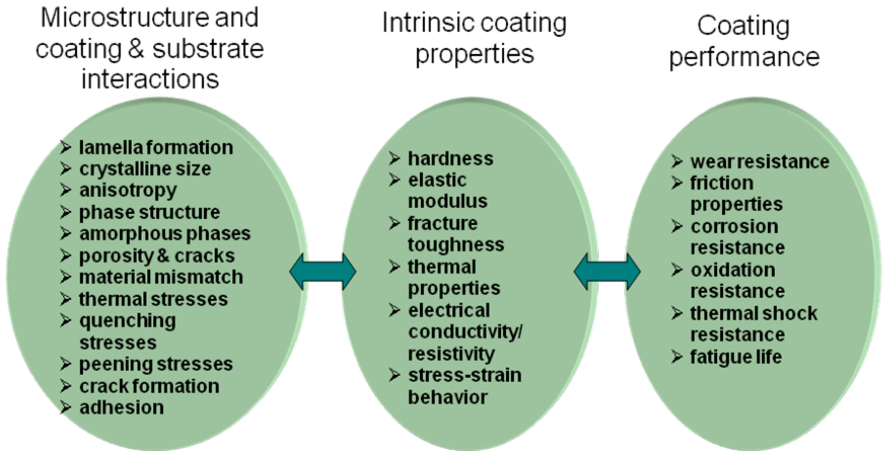
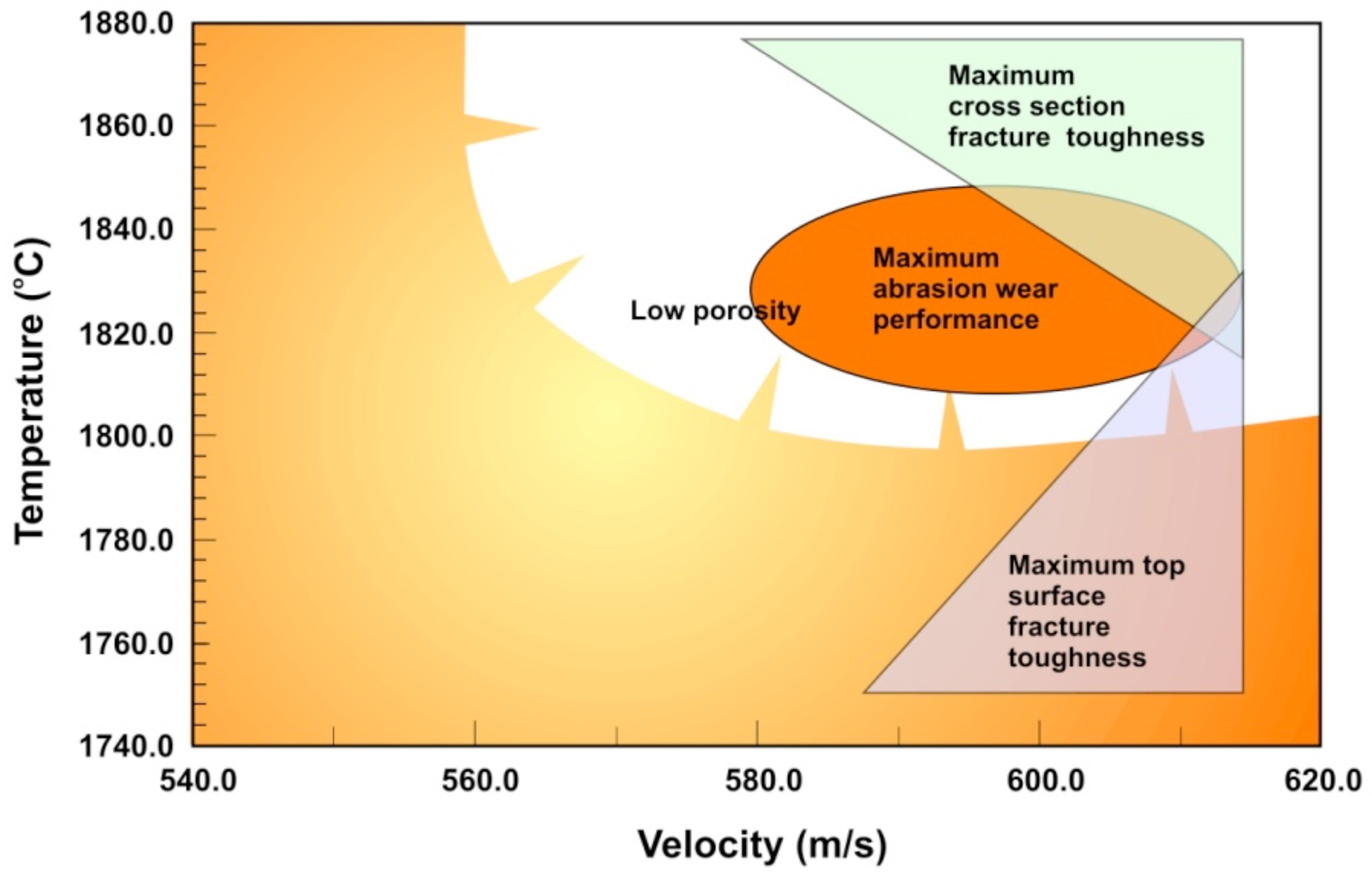
The optimization of the coating microstructures and properties is a challenging task, not to mention the performance of the coating in a particular environment or application as presented in
Figure 10. There are a number of influencing factors and interdependencies that influence the intrinsic coating properties as discussed above. These interdependencies are complicated and sometimes even impossible to handle although the systematic process optimization approach described in the previous chapter shows promise as an effective tool for such a task.
As described in previous chapters, the typical route for the optimization of coatings performance is via its intrinsic properties that in turn are controlled by the microstructure and coating/substrate— system interactions. For example, in wear applications such coating properties as hardness, elastic modulus and fracture toughness, along with porosity of the coating, are under focus. If the application requires environmental resistance, whether against corrosive media or oxidation, it is important to control the phase structure of the coating as well as its porosity. In both cases, also the system properties, i.e., adhesion of the coating to the substrate and internal stresses must be under control to obtain a coating that has an optimal performance at the particular applications.
Before discussing the typical properties and the range of their variance in HVOF coatings we will introduce the most usual methods for characterizing the properties of HVOF coatings. It is important to acknowledge that although most of them are quite generally applied in materials characterization, thermal spray coatings bear many special features that must be taken into account when their properties are evaluated.
3.1. Characterization of Intrinsic Coating Properties: Special Features and Limitations
Characterization of coating microstructures and properties are usually carried out by methods developed for microstructural characterization in general. While most of these are directly applicable for HVOF coatings as well, there are certain precautions, which should be considered and taken into account. This concerns especially the preparation of samples for characterization of microstructural features of coatings.
3.1.1. Coating Hardness
Hardness of the coating is usually measured either from the cross section or the surface of the coating. Two types of methods are commonly used, i.e., traditional hardness measurement preferably carried out by Vickers' method or instrumented indentation techniques, where the hardness is evaluated from the load-displacement data.
When Vickers hardness is measured from the cross-section of thermal sprayed coating the applied loads should not lead to the formation of cracks. According to standard EN ISO 14923 the thickness of the coating should be at least three times the indentation diagonal
d. This is observed to be the absolute minimum thickness required to make reliable measurements and, to be on the safe side, the upper corner of the indentation should be located at least at a distance of one diagonal from the surface of the coating, and the lower corner a similar distance away from the substrate. When Vickers hardness is measured from the top surface of the coating, the thickness is recommended to be ten times the plastic depth of the indentation to avoid any effect from the substrate on the measurement. Therefore, nanoindentation is currently used for a more detailed mechanical property characterization, such as for measuring hardness and elastic modulus of individual phases like carbides or matrix material of the coating or even from single splats [
20-
22].
3.1.2. Elastic Modulus
There are several methods to deduce the elastic modulus or Young's modulus of the coating (E). Among them impulse excitation technique (IET), ICP sensor, and instrumented indentation test are most common. IET-standard procedures are described in ASTM E 1876-99 [
23] and ENV 843-2 [
24]. Elastic modulus can conveniently be determined by instrumented indentation. Values of E are calculated from the load-displacement data usually following the procedure proposed by Oliver and Pharr [
25]. Because of the elastic field of the indentation is always larger than the plastic field, the boundary conditions of hardness measurement described above should be considered to be minimum requirements for elastic modulus measurements. Since elastic modulus is very sensitive to coating microstructure and especially to coating porosity and other faults, its value can also be used when estimating the uniformity and quality of the coating in comparison to other thermally sprayed coatings.
3.1.3. Coating Toughness
The toughness of a material describes its ability to absorb energy before and during fracture [
26]. Because of the brittle nature of many thermal sprayed coatings, fracture mechanics play an important role in evaluation of the usability and performance of the coatings. Fracture mechanical theories, equations and measuring techniques of bulk ceramics, also possessing brittle nature, have been the starting point for studying the fracture behavior in the thermal sprayed coatings. Because of the required sample size in the methods developed for bulk materials, the indentation fracture toughness (IF) technique seems to be the only reasonable and suitable test for thermal sprayed coatings. The basic idea is to apply a large enough load with Vickers diamond pyramid tip to initiate cracks from the diagonal corners of the indentation mark. From the measured average crack length and applied indentation load, the fracture toughness (K
IC) can be calculated. It describes the critical stress intensity factor of mode I crack. Indentation fracture toughness K
IC can be measured from the cross-section or the surface of thermal sprayed coating. From the surface, one usually gets four corner cracks with the same length, and the boundary conditions described e.g., in JIS R 1668-2005 [
27] can be used.
Because the applied loads needed for the initiation of cracks in the fracture toughness measurement are higher than those used in the hardness measurements, one must check that the maximum plastic depth of the indentation is less than one tenth of the coating thickness. When measuring fracture toughness from the cross-section of the coating, the obtained result describes the lamellar cohesion. Cracks in the coatings grow more easily in the direction parallel to the substrate—vertical cracks are usually produced only in the brittle ceramic coatings. The cracks parallel to the substrate will usually initiate and propagate in the lamella boundary. Because of this preferred crack growth direction, the equations and boundary conditions developed for homogenous bulk ceramics do not apply and some modifications are needed. If the cracks grow only in the parallel direction, the average crack length (l) should be calculated by dividing the total crack length (= sum of the cracks) by two, not by four as when measured from the surface. One requirement is that the cracks should initiate near the diagonal corners. If other major cracks than the corner cracks are developed, the measurement is not anymore valid. This prerequisite may lead to difficulties of finding valid measurements, especially if the coating possesses large residual stresses [
22].
3.1.4. Coating Porosity
There are a number of different methods that can be used for determination of the coating porosity. Nondestructive methods such as water adsorption, mercury intrusion porosimetry, helium pycnometry, Archimedean method, and other more sophisticated and tedious methods such as small angle neutron scattering (SANS) or x-ray computed microtomography (CMT) [
28] have all been employed for quantitative measurement of porosity. Accurate counts of porosity and its distribution can be obtained by the latter two methods, but they both require special instrumentation, which is not generally available for industrial use.
The most common practice to analyze the porosity of a coating is to prepare a metallographic cross-section sample of the coating and to determine its porosity from the micrographs taken with light microscope or a scanning electron microscope (SEM) e.g., by image analysis. Porosity within a microstructure can in principle be easily detected by image analysis because of the contrast difference between the dark pores (voids) and the more highly reflective coating material with sufficient resolution. Some reports claim that image analysis can reproducibly detect and measure microstructural features (pores, cracks,
etc.) to a 95% confidence level within thermal spray coatings [
29].
There is a lot of criticism presented on this procedure since the preparation of the samples has a large influence on the values obtained,
i.e., the preparation may result in formation of pores (in brittle coatings such as ceramics) or closure of pores (in ductile metallic coatings) resulting in erroneous values of porosity. In ISO/TC107/WG1, porosity measurement of thermal sprayed ceramic coatings by SEM cross-sectional photography and image analysis has been evaluated by a number of participating members. In a round robin test organized by the working group, five samples having a different ceramic coating were tested by each participant to obtain the respective porosity values. Further examinations have also been conducted by NIMS in Japan about the role of image analysis software, SEM and surface polishing procedures to rationalize the reasons for the observed differences. A preliminary and partial analysis of these results is given in ref. [
30], and the final report is published as an ISO Technical Report TR 26946. The findings can be summarized as follows. The differences in grinding/polishing conditions of the cross-sectional sample have a major influence on the porosity value obtained. Especially the pressure during polishing has an important role. It could be hypothesized that if the grinding pressure in the beginning of the polishing procedure is too low, the defects formed during the specimen cutting and preparation are not removed completely and too high value of porosity is obtained. If the pressure applied in the polishing is too high the sample preparation itself results in pull offs and too high porosity value. Furthermore, it is important to recognize that the imaging mode in SEM has an influence such that secondary electron image (SEI) typically yields lower values of porosity than the backscattered electron image (BEI) because the distinction of the coating matrix and the pores is more difficult in the SEI image, and the fraction of image judged to be a pore as a result has decreased. Based on this hypothesis an optimum pressure can be found, which results in a minimum value of porosity. Whether this is the actual porosity of the coating or higher than the real value depends on the mechanical properties of the particular coating.
An additional challenge is that the total percentage of porosity does not always give enough information on the quality of the coating even if determined correctly. A more detailed account of pores and cracks is actually needed if the coating properties and performance are to be judged or predicted in more detail. Therefore it would be advantageous to divide the net porosity into classes, such as coarse and fine globular pores and crack networks according to their process of formation [
31]. Coarse pores refer to the size range of 3–10 μm pores, which are formed due to incomplete filling of interstices between impacting particles and previously deposited particles and typically formed, when the impacting particles are not completely molten. Fine pores are approximately 0.1–3 μm in size resulting from incomplete contact between lamellae during coating formation, and are therefore more or less oriented parallel to the substrate surface. The fine cracks approximately 0.01–0.5 μm in thickness result from relaxation of stresses generated within the splats during cooling and are thus oriented typically perpendicular to the lamellar plane.
3.2. Characterization of Coating Substrate System Properties: Challenges and Special Features
3.2.1. Coating Adhesion
Adhesion is one of the most important parameters, which influences the performance of thermal spray coatings—substrate system in practical applications of coatings. For many applications the adhesion of the coating is crucial to the performance of the coated part (e.g., [
32]]. Since no metallurgical bonds are formed between the rapidly cooling deposit and the substrate, the surface finish and the deposition conditions during the first spray pass are of uttermost importance in obtaining good adhesion.
A standard method for the measurement of adhesion of thermal spray coatings is by tensile adhesive test [
33]. This test is widely used although according to [
34] more than 80 other methods are reported for the measurement of coating adhesion. However, in case of porous ceramic coatings tensile adhesion testing has an inherent problem of being prone to penetration of the adhesive used for gluing the tensile test holder through the coating. This may result in too high a value of adhesion in the test. Therefore, other types of tests have been proposed for the measurement of adhesion of thermal spray ceramic coatings. Two of these are currently used or studied as an alternative for the tensile test,
i.e., shear test and scratch test.
Shear test developed in the frame of the EU-CRAFT-project “Shear Test for Thermally Sprayed Coatings” presents the main advantage of being possibly used in real time,
i.e., during the production process [
34]. The small size of the substrate specimens allows them to be prepared in advance in large quantities, and no limitation of porosity or adhesive strength of the adhesive occurs. Therefore the shear test is more relevant to represent the real stress state acting on the mechanical parts during service. The main disadvantages are the samples characteristics (coating should be thicker than 150 μm) and the need of special equipment to perform the test.
Scratch test, which is widely used for testing adhesion of thin films to substrate, is with modifications currently considered also for determining the thermal spray coating adhesion. ISO TC 107 WG 1 is carrying out an international round robin test to study the feasibility of this test for the determination of the coating adhesion of ceramic thermal spray coatings. Preliminary results of this round robin test will be available by the end of 2011.
3.2.2. Evaluation of Internal Stresses
An important coating-substrate system property is the residual stress state of the coating after spraying. There are only few methods that can be used to measure the residual stresses of thermally sprayed coatings. The generally applied method for measuring the residual stresses in metallic materials is by XRD using standard
d vs. sin
2 ψ XRD techniques (see e.g., [
35]]. In order to apply this method for the determination of residual stresses of thermally sprayed coating one needs to know the so-called X-ray elastic constants (XEC). XEC can be calculated using techniques based on the mechanical loading of the samples. However, the experimental behavior of the thermally sprayed coatings shows that the calculation of XEC is unreliable. Considering the characteristics of dense material to which the X-ray diffraction is sensitive, the use of XEC values calculated for the same phase of the bulk material can, according to [
36], be used for the determination of stresses in the coatings with an engineering accuracy.
When internal stresses are measured during spraying using the so called
In-situ Coating Property (ICP) sensor, it is possible to adjust the residual stresses to a large extent during spray by controlling the deposition parameters. In this way, the various stages of stress build-up can be monitored and the various stress contributions can be evaluated separately. The ICP sensor can also be used to extract in-plane elastic modulus of the coatings deposited. It is based on laser sensing of deflections in a strip during thermal spraying which is converted to sample curvature. A simultaneous measurement of temperature is achieved via multiple thermocouples. Elastic modulus and CTE of the coating can be calculated from the coating-substrate composite curvature change due to thermal mismatch [
37].
3.2.3. Evaluation of Wear Resistance
Wear resistance of thermally sprayed coatings is of high interest for many applications. In general, wear resistance of a coating in a particular environment is a system property influenced by the coating and substrate material and in particular the type of wear environment. Therefore, it is impossible to quantify the wear resistance of the coating accurately without knowing these factors. However, for particular types of wear environments there are tests, which give relative performance of different coatings quite accurately. One of the most used wear tests for thermally sprayed coating is the rubber wheel abrasion test (e.g., ASTM G-65), which is meant for testing material's resistance against abrasive type of wear. These tests are also extensively used for a wider screening of coatings, since the possible problems in coating microstructure (not so easily observed e.g., by metallographic means) are often manifested in the results of the abrasion test. Other tests exist for other types of wear situations, such as tests for adhesive wear (e.g., pin-on-disc types of test) and tests for erosive conditions (various modifications exists, e.g., slurry test depicted in standard ASTM G75-95 [
38]).
3.2.4. Evaluation of Wet Corrosion Resistance
Corrosion resistance of thermally sprayed coating is always a system property. This is influenced first of all by the corrosive environment in question, but also by the coating properties (composition, phase structure and microstructure including the cracks and the pores) and the coating-substrate-environment interactions. It is very rarely possible to produce fully liquid or gas impenetrable coatings even by sealing the coatings afterwards. Therefore, it is not only the corrosion resistance of the coating, but of the substrate-coating system, which should be considered in each particular application where corrosion is a factor.
Measurement of the corrosion resistance of a coating-substrate system is typically carried out by immersion tests in actual conditions or by accelerated immersion tests in the laboratory. These tests in combination with metallographic and analytical studies help to identify the corroding parts of the system, whether this is corrosion of coating in general, selective corrosion of some specific phase of the coating, or corrosion of substrate via cracks or open porosity of the coating finally leading to coating detachment.
Electrochemical measurements may also be used to evaluate the response of coating—substrate system to corrosive environments. Typical measurement may include the determination of the free corrosion potential and the polarization behavior of the system. If the environment is selected such that the electrolyte causes corrosion only in the substrate, the corrosion current may yield information on the through porosity of the coating as well as on the possible passivation system while the pores of the coating are filled with corrosion products from the substrate.
5. Applications of HVOF Coatings
Due to the excellent characteristics of HVOF coatings as mentioned in the previous chapter, there is a large variety of suitable materials, different HVOF sub-processes, such as CJS, and hence the possibility to tailor coatings for a large variety of applications; therefore, the use of HVOF is broad among several industries, and is increasing all the time. Examples of application areas include process industry, where the coatings are applied to ball and gate valves; pulp and paper industry with coatings to rolls and blades; aerospace industry, where coatings are used for turbine vanes as bond coats for thermal barrier coatings, turbine sections, landing gears; and automotive industry, which applications include piston rings and cylinder bores [
16]. Even some ceramic coatings, which have been previously sprayed by plasma process, are sometimes applied by HVOF spray method. Also raw materials with small-scale component, e.g., nanosized carbides, have enhanced the HVOF coating properties and potential applications as well. In the following, examples of HVOF coating applications and materials are briefly presented.
Typical HVOF coating materials are metals and cermets. Variety of materials is almost endless, and therefore the application areas are wide among different industries. At a very low porosity, below 1 %, HVOF coatings are suitable for protecting the substrate material against corrosion. Because of high hardness combined with high bond strength to the substrate and good inter-lamellar bonding, the use of HVOF coatings is extensive for wear protection applications, such as paper and pulp processing rolls and other wear-resistant parts in paper machines. Increased use of ceramics, and their dielectrical and thermal properties, has opened the door for HVOF coating use in electrical applications and as environmental barrier coatings (EBCs) in power and aerospace industry.
Applications, where coatings are used for protection from wear and friction, are very broad with HVOF technique. HVOF hardmetal coatings containing carbides and/or nitrides, such as WC-CoCr, WC-(W,Cr)
2C-Ni, and (Ti,Mo)(C,N)-Ni/Co, have very good hardness and tribological properties and hence are suitable for wear protection of machine parts [
70]. HVOF sprayed WC-Co/NiCrFeSiB coating with high hardness values and low porosity has been studied for use in coal-fired power plant piping against erosion [
71]. Due to brittle nature of the hard metal coating, the applications and conditions must be carefully chosen.
In the energy industry, especially power plant boilers experience both high temperature corrosion and erosion, and HVOF coatings can be applied to protect the tubing in the boilers, especially in the superheater area. HVOF sprayed NiCr and Cr
3C
2-20NiCr coatings have proven very good high temperature corrosion resistance in biomass fired boiler exposures [
72]. NiCrBSi and Stellite-6 coatings tested in coal-fired boilers have shown good hot corrosion resistance [
73]. HVOF coatings, such as NiCrSiB and Ni-Cr-Fe-Nb-Mo alloys, for high temperature erosion and corrosion protection have been widely used in waste-to-energy plants in order to [
74]. Thermal barrier coatings (TBCs) are used for enhancing the service life of gas turbines and diesel engine components. The ceramic coatings are mainly manufactured with atmospheric plasma spraying (APS) due to high melting temperature of the materials, but the applied bond coats under the APS ceramic coatings to improve adhesion are increasingly made by HVOF technique, bond coat materials being e.g., CoNiCrAlY, NiCoCrAlTaY, NiCrAlY, or NiCr [
75].
Different material forming techniques require use of coatings, as the components deteriorate easily in the processes. Deep-drawing is a widely used sheet metal forming process in the aircraft and automotive industries. High tribological demands of the forming tools can be fulfilled with HVOF cermet coatings, such as superfine structured WC-Co, which has high hardness enhancing sliding and abrasive wear [
2]. HVOF coatings have been studied for the protection and upgrade of aluminum injection mould tooling, particularly for the low-cost and flexible manufacture of automotive components. Smooth, hard and very well bonded coatings with low porosity and homogeneous microstructure have been manufactured from WC-CoCr, and Cr
2C
3-NiCr through careful optimization of deposition [
76]. Steel sheet continuous hot-dip galvanizing bath with molten metal is a very detrimental process for the galvanizing components. Three different high temperature corrosion resistant HVOF coating types have been applied to galvanizing bath components. These include WC-Co, oxide-based, and quite recently developed MoB/CoCr coatings [
77]. Optimization of the coating composition and microstructure is of utmost importance in order to extend the operating lifetime of the galvanizing hardware. Also bond coats may be used because of the mismatch between coating and substrate material. HVOF WC-CoCr cermet coatings on aluminum substrate could be used for plastic injection moulds due to high hardness, low sliding wear, low porosity, and good endurance against impacts [
78]. MoCoB-Co/Cr cermet coating could be used for protection of glass sheet forming moulds because it has excellent high temperature properties, such as low friction coefficient to glass, oxidation resistance, and low mechanical abrasion [
79].
Hard chromium plating has been an excellent and very widely used technique, but due to carcinogenic effect of hexavalent chrome ion (Cr
6+) in the manufacturing process, finding substituting solutions for the technique has been extensively studied during the last decade and possibilities of thermal spray coatings have been explored as replacer. HVOF Co-base alloy Tribaloy-800 coating has shown good friction and wear properties also in high temperature (500 °C) [
1]. Due to good durability of the coating, it could be used for the protection of machine components vulnerable to frictional heat and wear, e.g., sliding surfaces such as high-speed spindle. To replace hard chromium coatings in applications under erosion-corrosion exposure, both HVOF sprayed WC-Ni and Cr
3C
2-NiCr have been tested to be promising alternatives for those conditions [
80]. Cr
3C
2-NiCr HVOF coatings manufactured from fine-scale and nano-fractioned powders have proved to have very good mechanical, wear and corrosion properties, and could therefore be used as substitute to hard chromium coating in applications such as cylinders in earth moving machines and piston rings and valve stems applications in automotive industry [
81,
82]. HVOF coatings can be applied to landing gears in aircrafts to replace the hard chromium coatings. The HVOF process provides high hardness, good wear strength and better resistance to fatigue with WC-CrC-Ni coating compared to hard chromium coating [
83].
Other versatile applications for HVOF coating include magnetic and biomedical use. HVOF sprayed ferromagnetic Fe-Si based deposits, which have been produced from nanostructured powder, can be used in several magnetic applications even at high temperatures [
84]. HVOF hydroxyapatite (HAp) coatings are applied in various biomedical applications due to excellent biocompatibility of HAp [
85]. Use of nanostructured Hap has been studied for biomedical use and the results are promising, as the coating exhibits high density and crystallinity, and good microstructural uniformity [
86]. In the biomedical field, HVOF-sprayed nanostructured titania coatings could be used for prosthetic devices and other applications, where superior mechanical behavior is required [
87].
6. Summary and Conclusions
In this work, HVOF thermal spray techniques have been reviewed. HVOF techniques have significantly developed over the last two decades and new modifications and improvements of the technology have been introduced on the market. The latest developments in spray technology also take advantage of the developments that have occurred in powder production, especially in nanostructured powders. However, in order to fully exploit the excellent properties of HVOF coatings, it is emphasized that optimization of the spraying process is a must. As compared to APS coatings, HVOF coatings offer a number of advantages in terms of coating microstructure and properties resulting in improved performance in many applications. This holds especially true for metal and cermet coatings. For the deposition of ceramic coating, HVOF process offers improvements of coating quality in spraying of ceramics such as alumina. However, deposition efficiency of HVOF spray is typically lower than that of APS, and may hinder the wider use of the HVOF in many applications despite the clear improvement of properties.
HVOF coatings are nowadays applied in a variety of industries. Major application areas are within industries where coatings are used for protection from wear, friction and corrosion. Other applications for HVOF coatings include, e.g., magnetic and biomedical use.


