1. Introduction
Rechargeable lithium–oxygen (Li–O
2) batteries are very efficient energy-storage devices and are used as power sources for electric vehicles (EV) and hybrid electric vehicles (HEV) because of their low cost, environmentally benign effects and high theoretical energy density (~3500 Wh·kg
−1), which is almost nine times higher than that of current Li-ion batteries (~400 Wh·kg
−1) [
1,
2,
3,
4]. Despite these favorable characteristics, their practical applications have still been hampered in the past decade because of their limited rate capability, poor cycling stability due to the instability of the electrode and electrolyte, and low round-trip efficiency induced by excessive polarization, resulting in a wide charge–discharge voltage gap [
1,
2,
3,
4,
5,
6,
7,
8]. These critical problems are predominantly caused by the O
2 cathode.
Many studies [
1,
4,
7,
8,
9,
10,
11] have shown that the electrochemical performance of Li–O
2 batteries depends on many factors, such as the nature and microstructure of the O
2 electrode, the formulation of the electrolyte (especially, the composition of the solvent), the possible presence of reactive contaminants (e.g., trace water) and the choice of catalysts. In order to enhance the properties of rechargeable Li–O
2 batteries, most studies have focused on the electrolyte formula, choice, and microstructure design of the O
2 electrode/electrocatalyst, and optimization of the operating parameters [
1,
3,
8]. Because there is poor electrochemical reversibility on the oxygen cathode side, a cathode catalyst that is highly active and has good chemical stability is necessary for good battery performance [
5,
12]. Therefore, a bi-functional cathode catalyst that facilitates the complete reversibility of oxygen reduction reactions (ORRs) and oxygen evolution reactions (OERs) at low polarization in Li–O
2 batteries is required. Several potential electrocatalysts that promote ORRs and OERs in Li–O
2 batteries have recently been proposed, including nitrogen-doped carbon, metal oxides, metal nitrides, precious and nonprecious metals, etc. [
1,
2,
6,
11,
13,
14,
15,
16,
17]. Among metal oxides, manganese oxide is a catalyst material of great interest owing to its low cost, environmental friendliness, abundance, and electrocatalytic activity for ORRs in Li–O
2 batteries [
1,
6,
16,
18]. Carbon-supported manganese oxide (MnO
x, Mn
3O
4, MnOOH et al.), which combine the good catalytic performance of manganese oxide with the optimized morphology and size of carbon materials, is a preferred electrocatalyst for ORRs and OERs in Li–O
2 batteries [
1,
19,
20,
21]. Therefore, this study of Li–O
2 batteries focuses on Mn
3O
4/C catalysts.
Ultrasonic spray pyrolysis (USP) is eminently suitable for the fabrication of heat-treated solid-state materials because the manufacturing process is a one-step process and produces spherical and uniform particles with a particle size that can be controlled. This study uses the USP method to prepare homogeneous spherical Mn
3O
4/C particles and uses various organic surfactants, such as Trition
® X-114 (TX114), Pluronic
® F-127 (F127) and Pluronic
® P-123 (P123), as structure-directing agents and residual carbon sources. The aim of this work is to develop a new heat-treatment method for the synthesis of high-surface-area Mn
3O
4/C catalysts and demonstrate the significant effect of morphology on the electrocatalytic performance of cathode catalysts for Li–O
2 batteries. We present a detailed study of the Li–O
2 electrochemistry of the Mn
3O
4/C material, using an electrolyte of 1 M LiPF
6 in a propylene carbonate (PC) solvent. The PC solvent is used because it was used in many of the initial studies on Li–O
2 batteries, in spite of its poor stability. Although there have been many studies of the use of Mn
3O
4/C materials in Li–O
2 batteries, few studies have examined the poor stability of the electrolyte because of its reaction with the superoxide radical (O
2•−) that is produced upon the discharge at the Mn
3O
4/C electrode. Therefore, as the reported in our early study [
6], aspects of the PC-based electrolyte reaction against O
2•− and the related kinetic information of O
2•− in the Mn
3O
4/C electrode are explored by studying rotating ring-disk electrode (RRDE) experiments and using a lithium-free non aqueous electrolyte because of the stability of the intermediate O
2•−. The O
2 solubility, diffusion rates of O
2 and superoxide radical (O
2•−) coefficients (
and
), rate constant (
kf) for the production of O
2•− and PC-electrolyte decomposition rate constant (
k) of the as-prepared Mn
3O
4/C electrode are measured.
2. Experimental Methods
Mn
3O
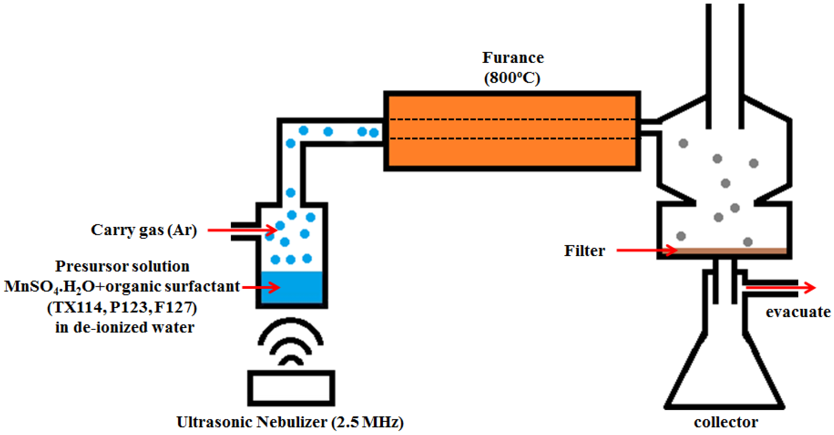
4/C composites were prepared using ultrasonic spray pyrolysis (USP) with manganese sulfate as the manganese ion precursors and organic surfactants as the structure-directing agents and carbon sources. The schematic diagram for the USP experimental apparatus is given in
Figure 1. A humidifier ultrasonically nebulizes a precursor solution to form micrometer-size aerosol droplets. The aerosol droplets are then carried by Ar gas into a furnace, where the droplets evaporate and the precursor decomposes. The final solid products were collected by filtration. A precursor solution was prepared by dissolving 90 wt % manganese sulfate monohydrate (MnSO
4·H
2O, Sigma Aldrich, St. Louis, MO, USA) and 10 wt % organic surfactants into deionized water, to achieve a 0.5 M concentration of MnSO
4. Three different organic surfactants were used: TX 114 (Trition
® X-114, Sigma Aldrich, St. Louis, MO, USA), F127 (Pluronic
® F-127, Sigma Aldrich, St. Louis, MO, USA) and P123 (Pluronic
® P-123, Sigma Aldrich, St. Louis, MO, USA). The homogeneous precursor solution was obtained by ultrasonic treatment and was converted into an aerosol using a 2.4 MHz ultrasonic nebulizer (Model WB-P2424FX, Whirl Best, Taoyuan City, Taiwan), which produces small droplets. The aerosol droplets were carried into a heated quartz tube (diameter: 25 mm, length: 30 cm) by a continuous high-purity Ar flow (500 mL·min
−1) for sulfate pyrolysis and microsphere solidification. The quartz tube was installed inside a split-hinge tube furnace, which was maintained at 800 °C. The solid particles that formed were collected in a vacuum filter at the other end of quartz tube. The final microsphere Mn
3O
4/C composites were isolated on 450 nm filter paper, washed sequentially with absolute ethanol and purified water several times, and dried at 110 °C for 6 h.
A Rigaku-D/MaX-2550 diffractometer (Rigaku, Tokyo, Japan) with Cu Kα radiation (λ = 1.54 Å) was used to obtain X-ray diffraction (XRD) patterns for the samples. The morphology of the sample was observed using a scanning electron microscope (SEM, Hitachi S-3400 Hitachi Limited, Tokyo, Japan). The Brunauer-Emmett-Teller (BET) method was used to measure the specific surface area of the powders (ASAP2020). Particle size analysis (PSA) used a Malvern particle size analyzer (Zetasizer Nano ZS, Malvern Instruments Ltd, Malvern, UK). The residual carbon content of the samples was determined using an automatic elemental analyzer (EA, Elementar vario EL III Elementar Analysensysteme GmbH, Hanau, Germany).
For electrochemical tests, the Mn3O4/C electrodes were prepared by wet coating. They were made from as-prepared Mn3O4/C composites with super P and a poly(vinylidene difluoride) (PVDF) binder (MKB-212C, Elf Atochem, Atofina, Serquigny, France) in a weight ratio of 64:16:20. The Mn3O4/C composites and super P were first added to a solution of PVDF in N-methyl-2-pyrrolidone (NMP, Riedel-deHaen, Seelze, Germany). The mixture was stirred for 20 min at room temperature using a magnetic stir bar, and then for 5 min using a turbine at 2000 rpm in order to produce a slurry with an appropriate viscosity. The resulting slurry was coated onto a piece of separator (Celgard 2400, Charlotte, NC, USA) and dried at 60 °C under vacuum for 12 h. The coating had a thickness of ~100 μm with an active material mass loading of 8 ± 1 mg·cm−2. The quantity of active materials on the electrodes was kept constant. The electrodes were dried overnight at 60 °C under vacuum, before being transferred into an argon-filled glove box for cell assembly. The Li–O2 test cell (EQ-STC-LI-AIR, MTI Corporation, Richmond, CA, USA) was constructed using lithium metal as the negative electrode and the Mn3O4/C electrode as the positive electrode. A solution of 1 M LiPF6 in a PC solvent was used as the electrolyte for all cells. After assembly, the test cell was removed from the Ar-filled glove box and attached to a gas manifold that was constantly purged with dry O2. The electrochemical tests were performed after the cell has been flushed with O2 for 6 h. The cells were galvanoststically cycled using a BAT-750B (Acu Tech System, Taipei, Taiwan) at a constant current of 0.2 mA·cm−2 with a voltage of 2.0–4.5 V vs. Li/Li+ at room temperature.
For RRDE experiments, an RRDE system (AFMT134DCPTT, Pine Research Instruments, Durham, NC, USA) with interchangeable disks consists of a 5 mm diameter glassy carbon electrode and a Pt ring electrode (1 mm width) with a 0.5 mm gap between them. The collection efficiency for this geometry is 0.24. The rotating ring-disk assembly was operated on a Pine AFMSRX rotator and CH705 Bipotentiostat (CH Instruments, Austin, TX, USA) with a computerized interface. Experiments were conducted using a three-electrode cell containing 10 mL of the electrolyte of interest. The cell was assembled in a dry Ar-filled atoms bag (Sigma-Aldrich Z108450, ST. Louis, MO, USA). The counter electrode was a Li foil that was connected to an Ag wire and isolated by a layer of Celgard 2400 separator to prevent convective oxygen transport to the electrode. The Ag/Ag+ reference electrode consisted of an Ag wire that was immersed into 0.1 M AgNO3 in CH3CN and sealed with a vycor frit at its tip. All potentials in this study are referenced to the Li/Li+ potential scale (volts vs. Li+/Li or VLi+), obtained by calibration of the reference electrode against a fresh lithium wire before the experiments (0 VLi = −3.46 ± 0.01 V vs. Ag/Ag+). The working electrode consisted of a catalyst-covered glassy carbon disk and was immersed into the Ar or O2-purged electrolyte for 30 min before each experiment. Prior to the RRDE measurements, alternating current (AC) impedance measurements determined the uncompensated ohmic drop between the working and the reference electrodes. A 10 mV perturbation (0.1 MHz to 10 MHz) was applied to the open circuit. The IR-correction to remove ohmic losses used the total cell resistance of ~293 Ω, as measured by AC impedance. The capacitive-corrected ORR currents were calculated by subtracting the current measured under Ar from that obtained in pure O2 under identical scan rates, rotation speeds and catalyst loadings.
3. Results and Discussion
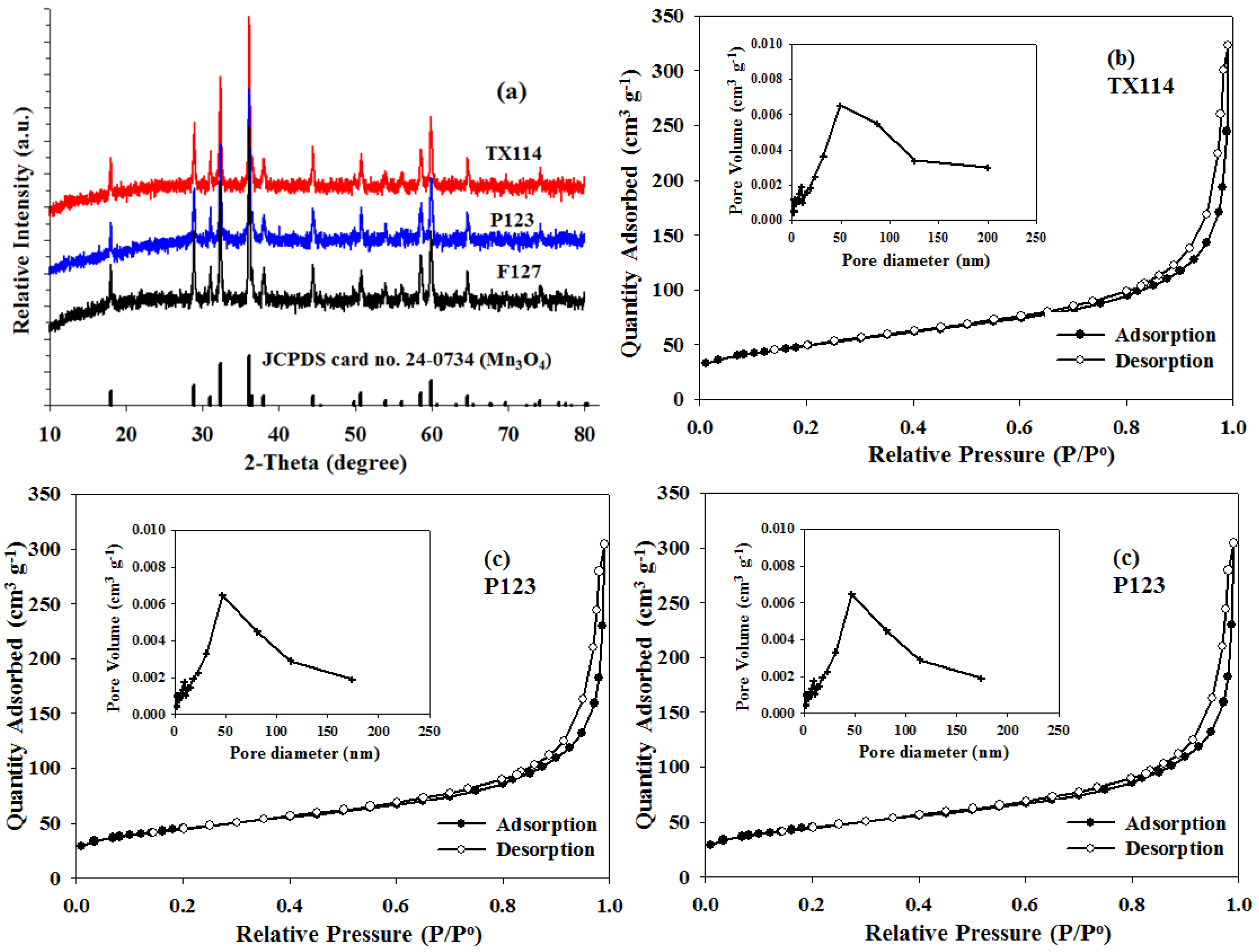
The phase composition and the crystal structure of the as-prepared composites were determined using the XRD patterns that are shown in
Figure 2a. In
Figure 2a, all peaks are identified as pure and well-crystallized Mn
3O
4 phase (JCPDS 24-0734), with a hausmannite-type tetragonal structure that is indexed to the I4
1/
amd soace group. The XRD curves do not show any evidence of the formation of crystalline or amorphous carbon. It appears that when using different organic surfactants as a carbon source, all of the final products probably remain amorphous or as low crystalline carbon.
Nitrogen adsorption-desorption isothermal measurements were performed to determine the pore structure of the Mn
3O
4/C composite.
Figure 2b–d shows that all of the as-prepared Mn
3O
4/C samples exhibit a typical type-IV N
2 sorption isotherms with distinct H3-type hysteresis loops at a high relative pressure between 0.8 and 1.0, indicating the characteristic of macroporous and mesoporous materials. The Barrett–Joyner–Halenda (BJH) pore size distributions for all samples are shown in the inserts of
Figure 2b–d along with a peak that is centered at 50 nm. The minor broad distribution peak that ranges between 100 and 200 nm corresponds to the macropore region and is probably a result of the space between aggregated particles. Many studies [
13,
22,
23] have shown that the wide variation in meso/macro pore size increases the cell capacity of Li–O
2 batteries because it results in a large electrolyte/electrode contact area and favorable distribution of the discharge products, such as lithium peroxide, in the cathode discharge. The BET analysis shows respective specific surface areas of about 28.9, 23.3 and 23.0 m
3·g
−1 for the TX114, P123 and F127.
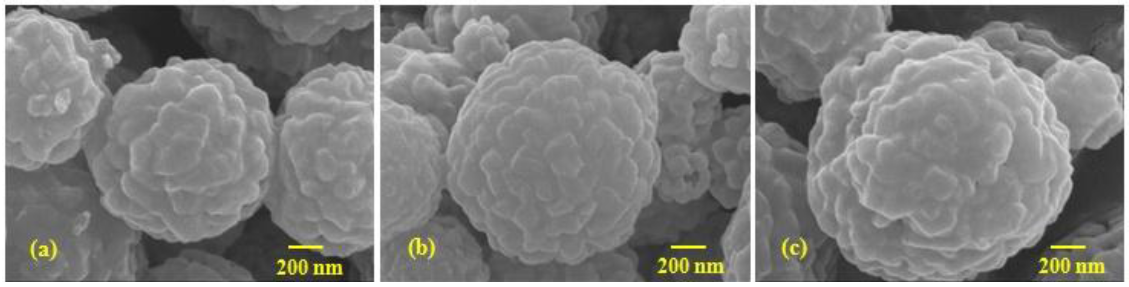
The morphology of the as-prepared Mn
3O
4/C composites was observed by SEM, as shown in
Figure 3. The SEM images of the Mn
3O
4/C composite show that the shape of the Mn
3O
4/C powder is close to spherical and the size is narrowly distributed between 0.9 and 1.3 μm, although a few agglomerates exist. The mean particle sizes of the TX114, P123 and F127, as determined by PSA, are about 0.86, 1.04 and 1.51 μm, respectively. These values are in good agreement with the measurement from SEM (
Figure 3).
Table 1 shows the residual carbon content, the particle size and the BET surface area for all of the as-prepared Mn
3O
4/C composites, using TX114, P123 and F127 surfactants. In order to ensure that there were equal amounts of residual carbon in the composites, the final content of the residual carbon of all of the samples was maintained at approximately 2–3 wt %. The data in
Table 1 demonstrates that the composite from TX114 has a smaller particle size, which results in a larger surface area. The particle size increases, which is consistent with the decrease in the specific surface area, from 28.9, 23.3 and 23.0 m
2·g
−1, for the TX114, P123 and F127, respectively.
Due to the study of the electrocatalytic activity of the as-prepared Mn
3O
4/C samples, the following discussion of the electrochemical tests makes comparisons between Super-P carbon (SP) and as-prepared Mn
3O
4/C materials. Mn
3O
4 is a highly active ORR catalyst and has recently been used as an O
2 cathode catalyst in Li–O
2 batteries [
5,
19,
21]. Therefore, it is essential to determine the kinetics of ORR for the as-prepared Mn
3O
4/C composites. The rotating ring disk electrode (RRDE) technique was used to determine the kinetics of ORR, since the ORR current is strongly affected by hydrodynamic conditions. In an early paper by the authors [
6], the kinetics of ORR for a MnO
2/C composite was studied and the O
2 solubility, the diffusion rates of O
2 and O
2•− coefficients (
and
), the rate constant (
kf) for producing O
2•− and the propylene carbonate (PC)-electrolyte decomposition rate constant (
k) for the MnO
2/C material and SP were measured using RRDE experiments in a 0.1 M TBAPF
6/PC electrolyte. This study uses similar RRDE experiments to determine the kinetics of ORR for the as-prepared Mn
3O
4/C composites. The O
2•− produced in the first step of the ORR, when the Li–O
2 battery discharges:
In the PC-based electrolyte, the ethereal carbon atom in PC suffers from nucleophilic attacks by O
2•−, which yields carbonate, acetate, and formate species among others, according to Equation (2) [
24]:
The reaction rate constant,
kf, is evaluated using the Koutecky-Levich (K-L) equation for a first order reaction, as follows:
where
ik and
id respectively represent the kinetics and the diffusion limiting current density (A·m
−2),
n is the number of electrons that are exchanged in the electrochemical reaction,
F is Faraday’s constant (96485 C·mol
−1),
kf is the rate constant for reaction 1,
is the diffusion coefficient of O
2 in the solution,
υ is the kinematic viscosity, ω is the angular frequency of the rotation, and
is the saturation concentration of O
2 in the solution. The stability of an electrolyte against O
2•− is defined by the rate constant (
k) for Equation (2) and is quantified using the RRDE voltammetry [
6,
24]. The O
2•− that is produced at the disk electrode in Equation (1) and the amount of O
2•− are quantified at the ring electrode using the decrease in the collection efficiency,
Nk, for O
2•− at the ring electrode as the transient time increases. The correlation with the collection efficiency is the absolute ratio of the ring and disk currents and is characterized by the following equation [
6,
24,
25]:
where
A1 = 1.288,
A2 = 0.643ν
1/61/3, β = 3ln(
r3/
r2),
U =
k−1 tanh(
A1k) and
T2 = 0.718 ln(
r2/
r1), whereby
r1,
r2, and
r3 refer to the radius of the disk and internal and external ring radii, respectively; ν is the kinematic viscosity; ω is the rotation rate;
k is the rate constant for reaction 2; and
is the diffusion coefficient of O
2•−.
Ngeometrical is the geometrical collection efficiency of the RRDE corresponding to the fraction of a species electrochemically generated at the disk. This species is detected at the ring due to the lack of side-reactions with the electrolyte. From the measurement of
Nk at a given rotation rate (ω), the rate constant (
k) can be calculated by Equation (6).
Prior to estimating the value of rate constants (
kf and
k), the kinematic viscosity (ν) of the electrolyte and the diffusion coefficients of O
2 and O
2•− (
and
) must be quantified. These are listed in
Table 2. The estimation of the values in
Table 2 is reported in an early paper by the authors [
6].
Figure 4 shows the RRDE profiles for the Mn
3O
4/C and SP samples that are coated on the disk electrode. The disk and ring currents were recorded in an O
2-saturated 0.1 M TBAPF
6/PC solution at rotation rates between 300 and 2100 rpm. The Pt ring was maintained at 2.6 V
Li . The K-L plots for the disc current values at 1.30 V
Li (see
Figure 4) show the expected linear relationship between the inverse of the limiting current (
id) and ω
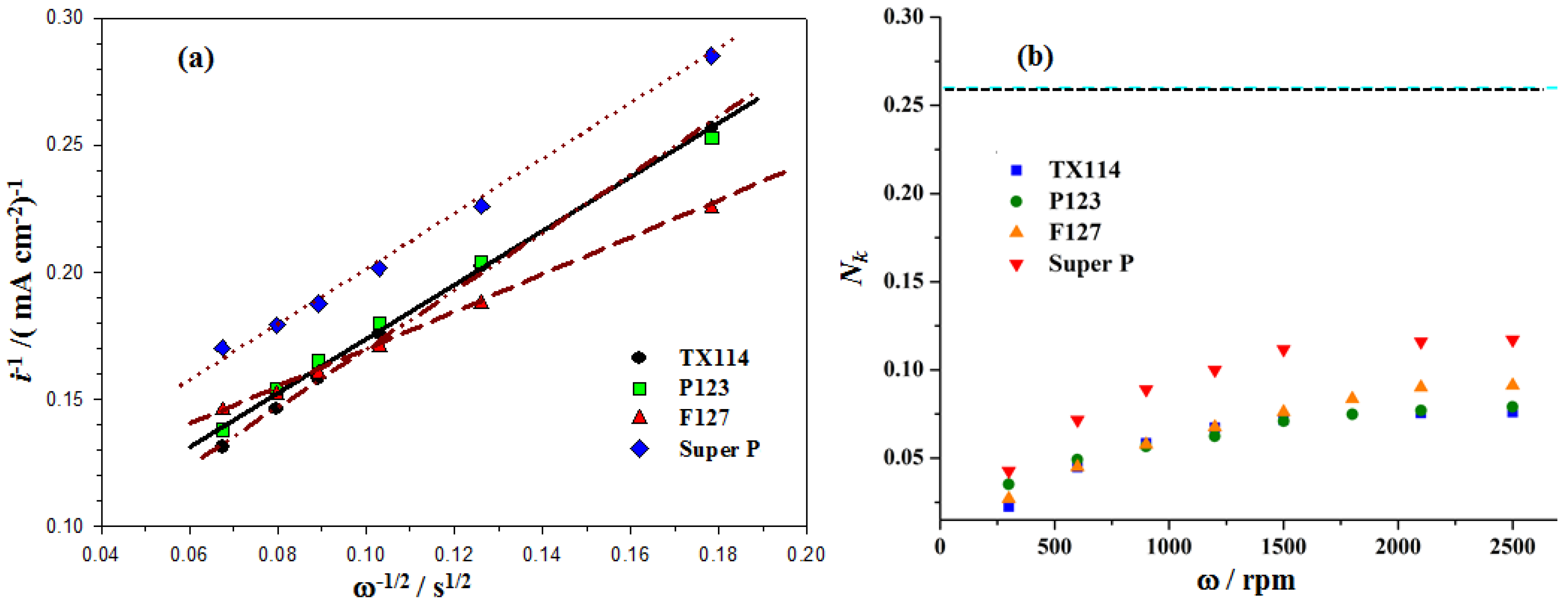
−0.5 (see Equation (5)). The rate constant for the production of O
2•−,
kf for the GC and the MnO
2/C-GC electrodes is obtained by linearly fitting the K-L plots of
i−1 vs. ω
−0.5 (see Equation (5)) as shown in
Figure 5a. The values of
kf for all of the as-prepared Mn
3O
4/C composites that use TX114, P123 and F127 surfactants and SP electrodes are 3.7 × 10
−2 cm·s
−1, 2.9 × 10
−2 cm·s
−1, 2.3 × 10
−2 cm·s
−1 and 2.1 × 10
−2 cm·s
−1, respectively. This result indicates that the Mn
3O
4/C cathode catalyst has a larger
kf value than SP, because there is a higher electrocatalytic activity for the first step of the ORR (see Equation (1)), so a higher concentration of O
2•− is produced. The TX114 sample has the smallest particle size so it has the largest specific surface area of all of the samples. This results in the highest activity for the ORR in the O
2 electrodes.
The RRDE profiles show that the ring current increases as the rotation rate increases because the shorter transient time at higher rotation rates reduces the reaction time between O
2•− and the PC electrolyte so a higher concentration of superoxide radical is oxidized at the ring, as shown in
Figure 4.
Figure 5b shows that the value of
Nk increases as the rotation rate increases and the individual constant value is close to ω = 2500 rpm for all samples. The values for
Nk at ω = 2500 rpm are about 0.07, 008, 0.09 and 0.1 for TX114, P123, F127 and SP, respectively. The PC-electrolyte decomposition rate constant (
k) for different samples is evaluated using Equation (6), using the
Nk value at a rotation rate of 2500 rpm and the kinematic viscosity (ν) and
values that are listed in
Table 2.
Table 3 shows the rate constant for the production of O
2•−,
kf, and the PC-electrolyte decomposition rate constant,
k, for the TX114, P123, F127 and SP electrodes. It is seen that the
k values for the Mn
3O
4/C-GC that is prepared using different surfactants are larger than that for the SP. These results also show that TX114 is the most active surfactant for the first step of the ORR (the largest rate constant;
kf). It produces the highest concentration of O
2•−, so the PC-electrolyte decomposes fastest because it is attacked by a large amount of O
2•−. A similar result was reported in an earlier study by the authors [
6].
To better determine the electrocatalytic activity of the electrodes, cyclic voltammetry (CV) and charge–discharge voltage measurements were performed in the Li–O
2 test cell to compare Mn
3O
4/C composite (prepared from TX114) and Super P carbon (SP). The CV plots for the O
2 electrodes that were prepared using TX114 and SP cycled between 1.5 and 4.5 V at 2 mV·s
−1 and for the 1 M LiPF
6/PC electrolyte are shown in
Figure 6a.
During discharge for a Li–O
2 cell, a single cathodic peak appeared at ~2.6 V, indicative of one-step oxygen reduction to produce reaction products by ORR. Upon charging, another anodic peak appeared at ~3.3 V, indicative of decomposition reaction products by OER. The comparison of CV curves for Li–O
2 cells with TX114 and SP cathodes were shown in
Figure 6a. From the CV curves, the reduction peak voltage is shifted toward a positive voltage, exhibiting electrocatalytic activity in the ORR of both samples. However, the TX114 produces more positive onset reduction peak potential and a larger peak current, which clearly demonstrate that the electrocatalytic activity of TX114 is superior to that of SP. The onset oxidation peaks that appear in the CV curves are about 2.6 and 3.1 V for TX114 and SP, respectively. Therefore, TX114, with its lower onset oxidation peak, is more efficient for Li
2O
2 decomposition and has higher catalytic activity for the OER. The initial charge–discharge voltage profiles for both samples at the current density of 0.2 mA·cm
−2 are shown in
Figure 6b. The charge–discharge profiles for the TX114 electrode exhibit much lower charge overpotential than do those of the SP electrode, although the reduction of the total overpotential is only about 30%. The round-trip efficiencies of the Li–O
2 batteries with a TX114 electrode were lower than those with the SP electrode. These results demonstrate that the Mn
3O
4/C composite can facilitate the complete reversibility of ORR and OER at low polarization for a Li–O
2 battery. This finding is in good agreement with the results for the CV measurement. Obviously, the initial discharge capacity for the TX114 electrode reached a higher value of 1639 mAh·g
−1 and the corresponding discharge plateau was up to 2.64 V. By contrast, the SP electrode delivered lower discharge capacity of 752 mAh·g
−1 at the same current density, which may refer to its lower ORR catalytic activity.
Figure 7a shows the discharge curve of Li–O
2 batteries utilizing the TX114 electrode at the different current densities of 0.2, 0.4, 0.8 and 1.0 mA·cm
−2. With an increase of the discharge current density, the achieved capacity and cell potential were reduced, due to the internal resistance of the cells. The discharge capacities at a current density of 0.4, 0.8 and 1 mA·cm
−2 shown in the insert of
Figure 7a were found to be 1360, 994, 715 mAh·g
−1, respectively. The cycling performances of Li–O
2 batteries with TX114 and SP electrodes at a current density of 0.2 mA·cm
−2 are shown in
Figure 7b. As seen, the discharge capacity of the Li–O
2 battery with the TX114 electrode preserved about 1263 mAh·g
−1 after 30 cycles, and the capacity retention was about 77%, as opposed to only 530 mAh·g
−1 discharge capacity (60%) for the SP electrode. These results indicate the superior cyclic stability of the TX114 electrode compared to the SP electrode. However, the capacity retention remained rather poor for both electrodes, with the discharge capacities dropping dramatically to below 80% after 30 cycles due to the continuous rise of the resistance. Until now, poor cycling stability has remained a significant challenge for Li–O
2 cells. Many investigations [
1,
2,
11,
17,
26,
27,
28] have shown that the biggest obstacle for cycling in Li–O
2 cells is the decomposition of the electrolyte during the charge–discharge process. Our above RRDE results demonstrate that PC is a poor stable electrolyte solvent in Li–O
2 battery due to its reaction with the superoxide radical at the O
2 electrode, in agreement with the literature [
1,
11,
17,
24]. The above galvanostatic charge–discharge tests show that the discharge capacity of Mn
3O
4/C composite (TX114) was higher than that of our previous MnO
2/C composite [
6]. This indicates the superior electrocatalytic activity of Mn
3O
4/C composite compared to MnO
2/C composite. Obviously, Mn
3O
4/C composite that uses TX114 has higher activity as a bi-functional catalyst and delivers better ORR and OER catalytic performance in Li–O
2 batteries. Except PC, the choice of a novel electrolyte is very important, to avoid decomposition by O
2•− attack when applying an active catalyst on the cathode material in Li–O
2 batteries. More detailed RRDE experiments and analysis will be performed in order to estimate the decomposition rates for various electrolytes with different bi-functional oxygen electrocatalysts.


