Article

Performance Evaluation of an Indoor Positioning Scheme Using Infrared Motion Sensors

Electronic Engineering Departmen, Kwangwoon University, 447-1 Wolgye-dong, Nowon-gu, Seoul 139-701, Korea
*
Author to whom correspondence should be addressed.
Information 2014, 5(4), 548-557; https://doi.org/10.3390/info5040548
Submission received: 13 June 2014 / Revised: 15 October 2014 / Accepted: 16 October 2014 / Published: 27 October 2014
(This article belongs to the Special Issue Advances on the Internet of Things in a Smart Environment)

Abstract

:
Internet of Things (IoT) for Smart Environments (SE) is a new scenario that collects useful information and provides convenient services to humans via sensing and wireless communications. Infra-Red (IR) motion sensors have recently been widely used for indoor lighting because they allow the system to detect whether a human is inside or outside the sensors’ range. In this paper, the performance of a position estimation scheme based on IR motion sensor is evaluated in an indoor SE. The experimental results show that we can track the dynamic position of a pedestrian in straight moving model as well as two dimensional models. Experimental results also show that higher performance in accuracy and dynamic tracking in real indoor environment can be achieved without other devices.

1. Introduction

Internet of Things (IoT) for Smart Environments (SE) is a new scenario that obtains useful information and provides convenient services to humans via the use of sensors and wireless communications [1]. Infra-Red (IR) motion sensors have recently been widely used in indoor lighting allowing systems to detect whether a human is inside or outside the sensors’ range.
Indoor positioning and tracking infrastructure devices play an important role in our life, including home safety, public services, and other commercial or military applications [2,3]. Various indoor positioning techniques have been developed in the past few years [4,5,6], and they can be classified into the following two classes: network-based methods and sensor-based methods. Network-based methods have the advantages of wireless location and indoor positioning [7]. They can be used for location estimation under situations where Global Positioning System (GPS) solutions are not applicable. In the network-based approaches, time of arrival (TOA) and time difference of arrival (TDOA) are two time-related parameters usually used for estimating the location of a mobile target [8]. Moreover, various wireless location schemes using angle of arrival have also been extensively investigated in the past [8]. Motion sensors allow us to detect whether a human is inside or outside the sensor range. They are small, inexpensive, low-power, easy to use and do not wear out. For those reasons, the IR motion sensors have been widely used in indoor lighting energy-saving systems to turn on or off the lights as people approach or depart from lights. Particularly, for the uncrowded environment such as office buildings at night and stairways, pyroelectric IR (PIR) sensors are widely employed. In addition, using cameras to monitor people in an uncrowded environment at night wastes energy and also provokes privacy problems. To address this problem, in this paper, an indoor positioning scheme based only on IR motion sensors is introduced and its performance is evaluated in an indoor environment. According to the experimental results, we can determine the dynamic position of a pedestrian in a straight moving model and also track the route even if the movement of a pedestrian is in two dimensions.
The rest of the paper is organized as follows: In Section 2, related works about positioning scheme using IR sensors and experimental environments are briefly described. In Section 3, performance evaluation of the proposed scheme is given. Finally, concluding remarks are given in Section 4.

2. Related Works

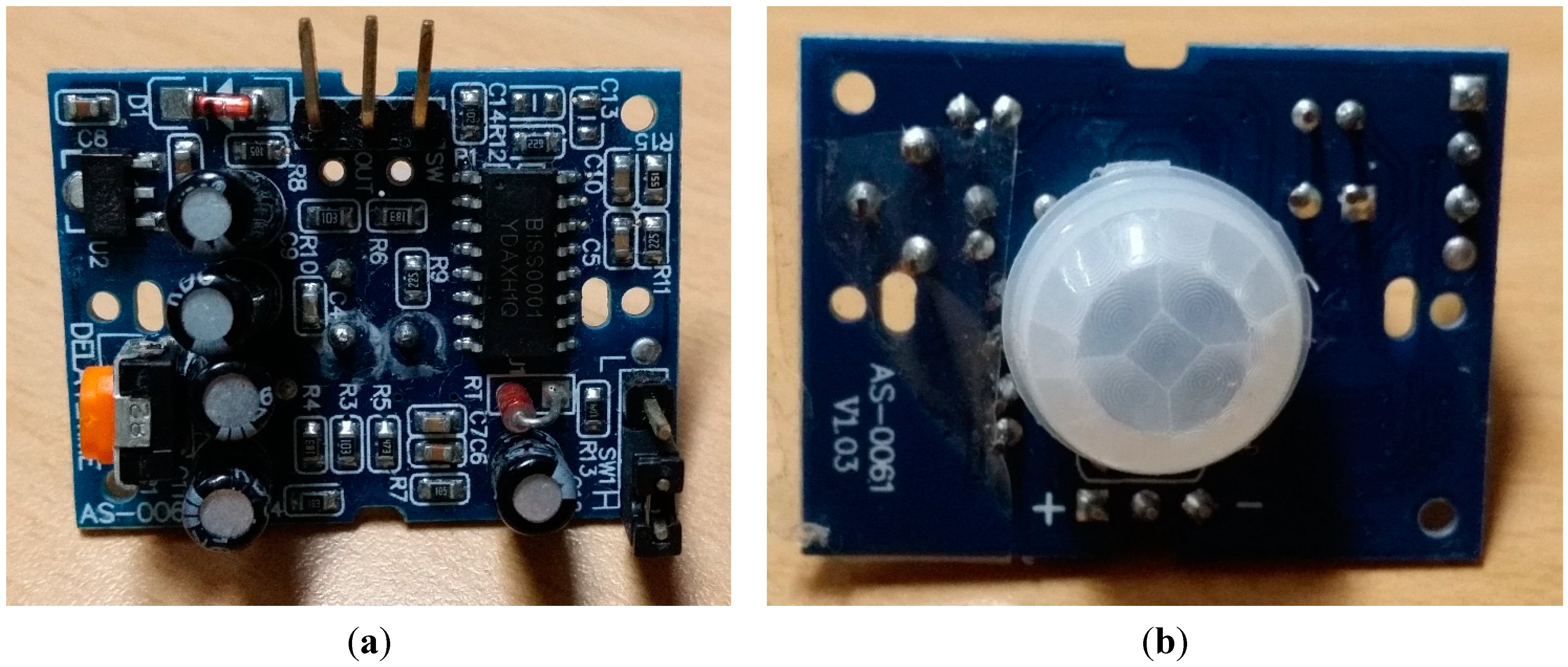
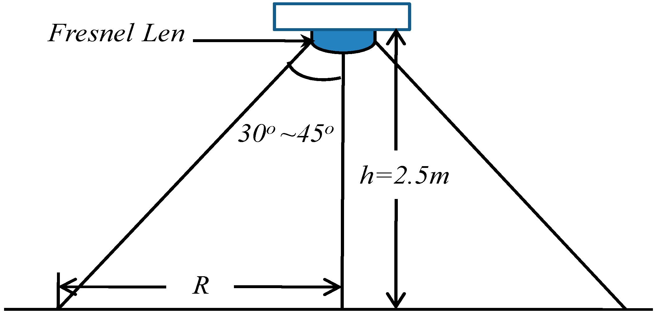
2.1. Positioning Scheme using PIR Sensors

Motion sensors are commonly used to detect whether a human has moved in or out of the sensors’ range. The sensors are small, inexpensive, low-power, easy to use and do not wear out. For those reasons, they are commonly found in appliances and gadgets. They are often referred to as PIR, “Passive Infrared”, “Pyroelectric”, or “IR motion” sensors. PIR sensors are commonly used for many basic projects or products to detect whether a person has approached, entered, or left the area. We choose the NT0071 module (Figure 1) for this study. The specification of the NT0071 module is given in Table 1. Although all PIRs work in the same way, each PIR has slightly different specification. Through a lot of tests, we found that the sensitivity range of IR motion sensor can be up to 2.5 m, i.e., the fixed height is equal to 2.5 m at the condition of 90°. As shown in Figure 2, when a warm body like a human or animal passes by or leaves the sensing area, the sensor will be turned on and switch to a differential state.
The PIRs cannot determine the distance between people and the sensor, but it can detect whether a person moves in or out the sensing area with the assistance of control board. On the other hand, we can track the movement of a person by using a couple of sensors that are fixed within certain distance. The PIR sensors are connected to the control board and the state information can be read. The PIR sensors used in the experiments have a 3-pin connection at the bottom. The jumpers of all the sensors are setup in the H position, and the LED stays on the entire time when something is moving within the sensing range. That is called “retriggering”. A general microcontroller, Arduino MEGA 2560, is used as the single board microcontroller.
Table 1. Feature and Electrical Specification of NT0071.
Compact size24 × 32 mm
DC Supply current5–20 V
Current drain50 µA
Voltage outputHigh/Low level signal: 3.3 V
Delay time5 s–18 min
Infrared sensordual element, low noise, high sensitivity
Operation temperature−15–70 ˚C
Figure 1. Direct current Infra-Red motion sensor NT0071.
Information 05 00548 g001
Figure 2. Detection range of Infra-Red motion sensor.
Information 05 00548 g002
Figure 3. Schematic of experiment.
Information 05 00548 g003

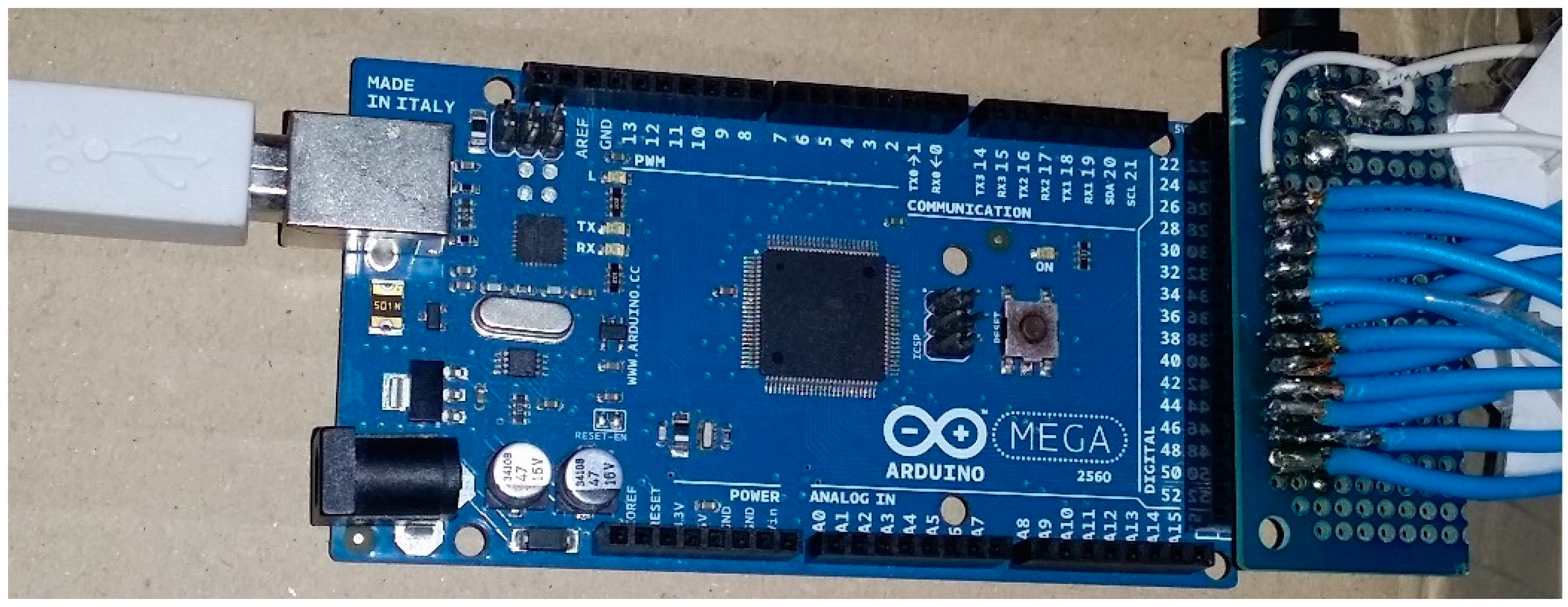
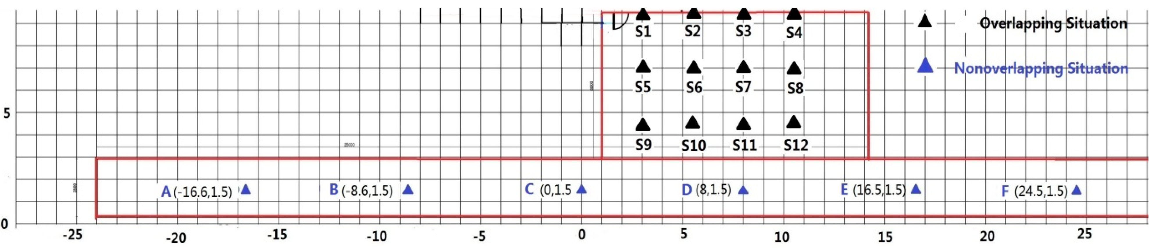
2.2. Experimental Environments

To evaluate the effectiveness of the proposed scheme based on PIR sensors, the experiments were performed on the sixth floor of the Hwado building, located in Kwangwoon University. The layout scheme of this experiment is shown in Figure 4. In the figure, the grid interval is 1 m. Twelve PIR motion sensors are installed in the lobby in an overlapping situation. The distance between adjacent sensors is 2.5 m, which is half of the average range radius of the motion sensors. Sensors A–F are fixed on the top of the hall for the non-overlapping situation. The distance interval is 8 m, which is much larger than the average range radius of the sensors. In the non-overlapping situation, a person moves from A–F to test the positioning performance of the proposed method. In the overlapping situation, four different routes, 9➔10➔6➔7➔4, 9➔10➔7➔4, 9➔5➔6➔7➔8➔4 and 9➔5➔2➔3➔8➔12, are tested. The red line shows the boundary of the test space and triangles indicate the positions of the sensors.
Figure 4. Layout of experiments.
Information 05 00548 g004

3. Performance Evaluation of Proposed Scheme

3.1. Non-Overlapping Situation
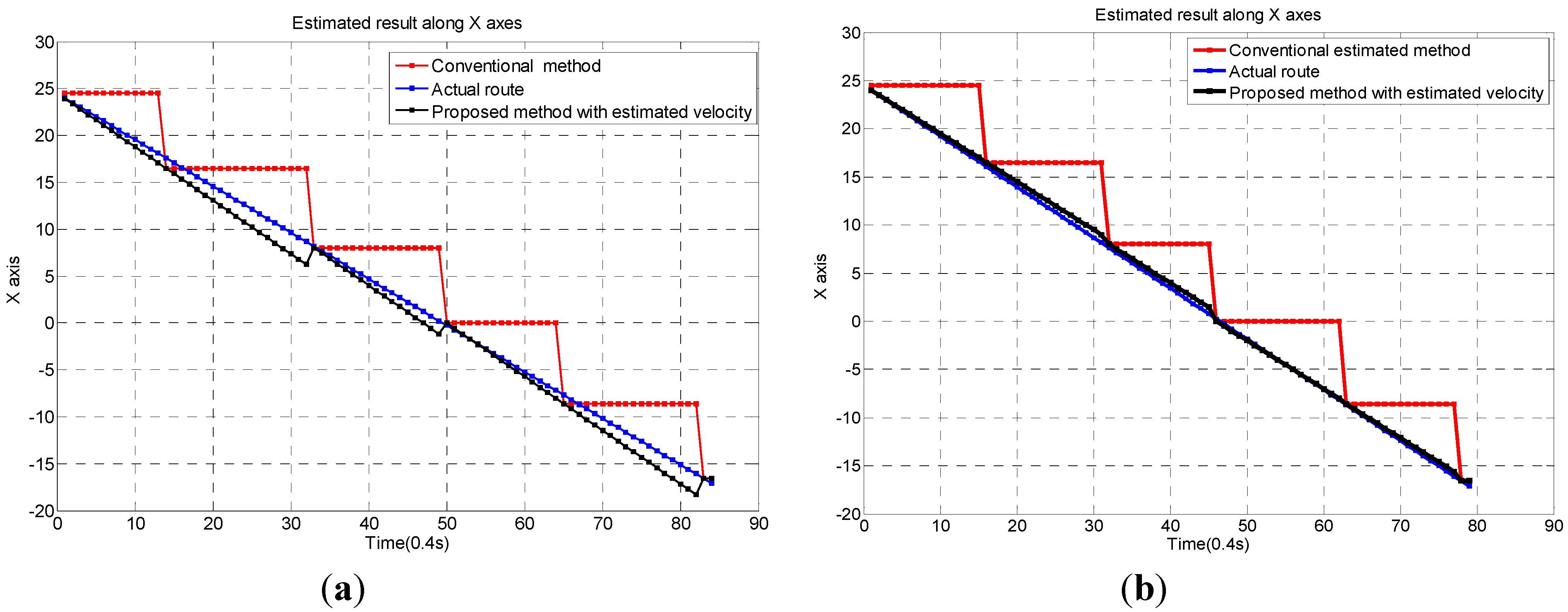
In this situation, the processing of tracking the walking route of a target can be divided into two steps. First, we determine the approximate route of moving target by connecting the coordinates of the working motion sensors in detection order. Second, we compute the dynamic speed of moving target with the assistance of a counting program. As the locations of motion sensors are known, the distance between them can be easily calculated. Beyond that, the control program keeps counting the moving time of the target as soon as it gets into the range of the corresponding motion sensor before entering the range of the next sensor. Hence, based on the moving time and distance between the two adjacent motion sensors, the moving speed of the target can be estimated. Therefore, we can determine the dynamic position of the target with the parameters obtained in the two steps.
When a person moves straight from sensor A to sensor F as shown in the layout scheme, the sensor will be turned on as soon as the person enters the range of each sensor. As a comparison, the estimations using the conventional area estimation method are also calculated. Comparisons of the estimated results along X axis are shown in Figure 5 and Table 2. Results show that a high position accuracy and dynamic tracking of moving target can be achieved by the proposed method under the assumption of straight moving model.
Figure 5. Comparison of Estimated results with different persons. (a) Person 1; (b) Person 2.
Information 05 00548 g005
Table 2. Estimated mean errors in the non-overlapping situation.
Route A➔B➔C➔D➔E➔FConventional methodProposed method
Person 13.52630.3940
Person 23.94180.3504

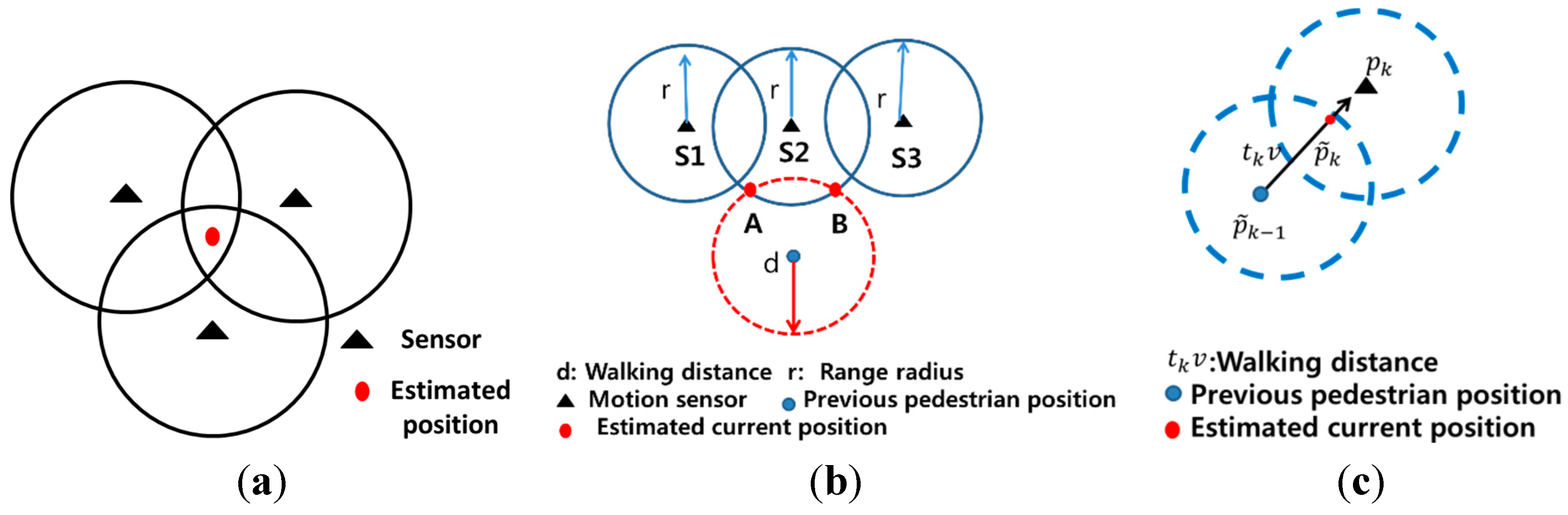
3.2. Overlapping Situation

To evaluate the performance of the system in the overlapping situation, the walking velocity and frequency of an average person are already known. In this subsection, the average walking velocity is set to 1.24 m each second, and the average walking frequency is 1.75 Hz; taken together, this means a pedestrian takes 570 ms to complete each step.

3.2.1. Proximate Method

The motion sensors allow us to detect when a person has moved into the sensors range with the assistance of control board. Therefore, if more than one sensor can identify the pedestrian within the same period of time, it suggests that the person is located in an overlapping coverage region, which can be used to determine the position of a person. In other words, the basic idea of multi-reference area estimation is to compute the intersection of all overlapping regions and use the overlap information to estimate position. In the overlapping situation, weight factor that can reflect the distance between the estimated position and the reference sensors is calculated based on the active time period between adjacent reference motion sensors. In our experiment, pk−1, pk, and pk+1 represents the position of three sensors Sk−1, Sk, and Sk+1, respectively. The tk is the active time period from the start of sensor Sk−1 to the start of sensor Sk. The walking distance that can reflect the approximate position of user in the range of Sk−1 before the person moves into the range of Sk can be calculated as dk = tkv. The tk+1 represents the active time period from the start of sensor Sk to the start of sensor Sk+1. It reflects whether the pedestrian has finished his one step before the next sensor Sk+1 is turned on. If tk+1 is smaller than average walking time 600 ms for each step, it suggests that the pedestrian has not finished his one step before the next sensor. Alternatively, it means the sensor Sk+1 is turned on by the next action of the pedestrian. Based on these two factors, six cases have been identified and implemented to estimate the position of the moving people as shown in Table 3. p k 1 ~ is the estimated position of the pedestrian. R is the average range radius of motion sensor. Figure 6a shows a simple example of proximate area estimation method. In that case, we chose the centroid of the coverage regions from three reference sensors as the estimated position.
Figure 6. Schematics of (a) proximate method; (b) circ-circ method; (c) Kalman filter approach.
Information 05 00548 g006
Table 3. Rules of Estimation.
Time period, tk, tk+1Estimated position p k 1 ~
Information 05 00548 i0012pk−1/3 + pk/3
Information 05 00548 i002pk−1/3 + 2pk/3
Information 05 00548 i003pk
Information 05 00548 i004
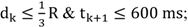
pk+1/5 + 2(pk−1 + pk)/5
Information 05 00548 i005
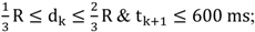
pk−1/5 + 2(pk + pk+1)/5
Information 05 00548 i0061/2(pk + pk+1)

3.2.2. Circ-Circ Method

The first step of circ-circ method is to find points of intersection from walking circle and motion sensing circle. As shown in Figure 6b, the red dot represents the possible position of the pedestrian. Second, select the position p k 2 ~ that has the smallest distance from the next active sensor as the current position of the moving target. For example, in the case of Figure 6b, if S1 is the next active sensor, A will be selected as the estimated position; if S3 is the next active sensor, B will be selected as the estimated position. Limited by sensor susceptibility and accuracy of average walking speed, unpredictable errors may affect the positioning performance. Therefore, we select the average value as an approximation and use the circ-circ method to estimate the position of the pedestrians p ~ k = 1 / 2 ( p k 1 ~ + p k 2 ~ ) .

3.2.3. Kalman Filter Approach

p ~ k 1 = ( x ~ k 1 , y ~ k 1 ) is the previously estimated position of the pedestrian, pk = (xk, yk) is the position of the next active sensor Sk. Given a known velocity of pedestrian, we can get the relationship between the predicted position p ~ k = ( x ~ k , y ~ k ) and the previous position p ~ k 1 , pk as follows:
Information 05 00548 i007
Information 05 00548 i008
Among them, tk is the active time period from the start of previous position to the start of the sensor Sk. p ~ 0 = ( x ~ 0 , y ~ 0 ) is the coordinate of the start point.
The Kalman filter addresses the general problem of trying to estimate the state of a discrete-time controlled process that is governed by the linear stochastic difference as per Equation (3) with a measurement zk, that is
Information 05 00548 i009
The random variable wk represents the process and measurement noise. Based on the Kalman filter measurement update equation, the estimated results with Kalman filter approach is given in Equation (4) as follows:
Information 05 00548 i010
where Kk is the Kalman gain.

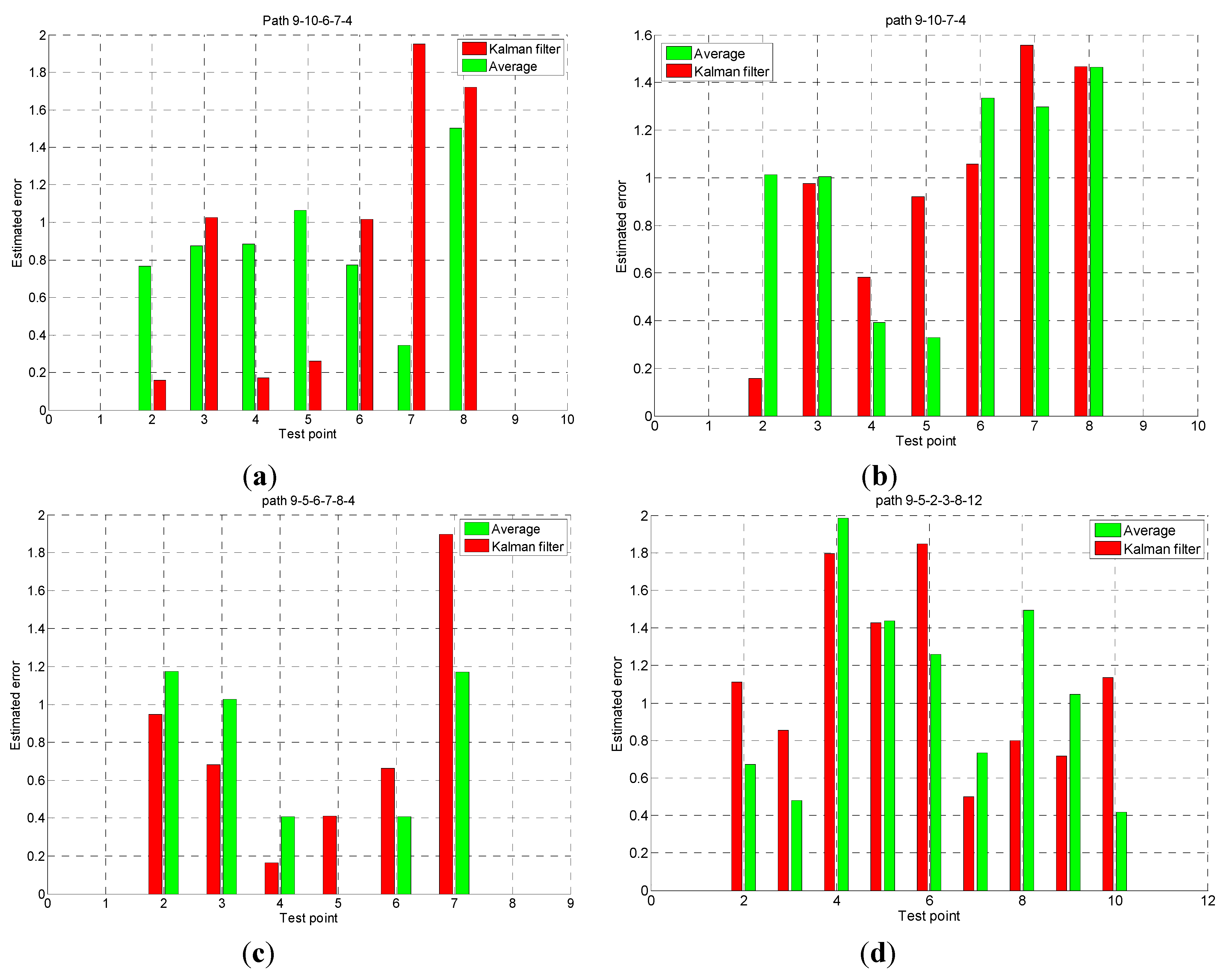
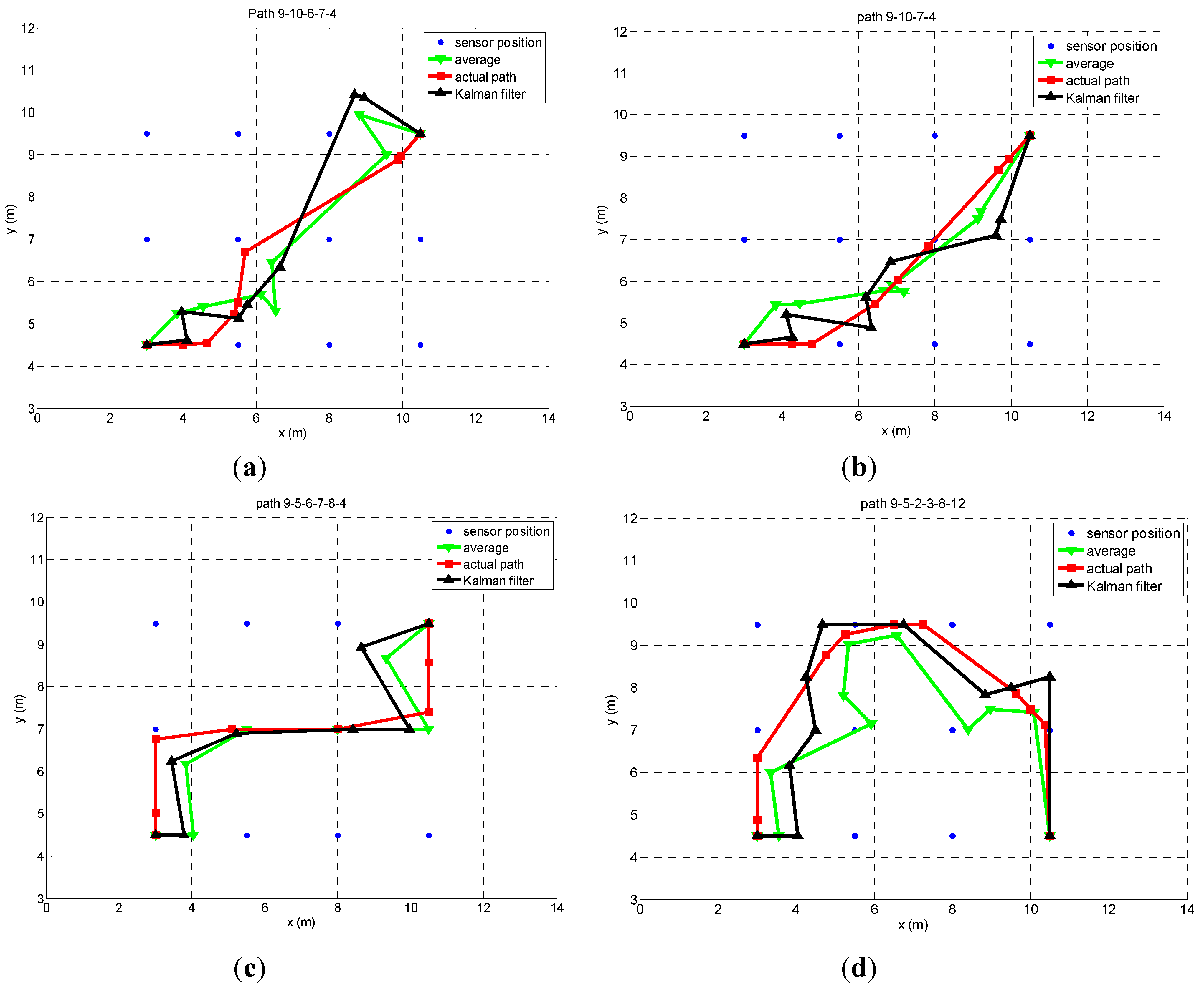
3.2.4. Tracking performance of Overlapping Situation

In this section, the tracking performance is evaluated in the overlapping situation for the route 9➔10➔6➔7➔4, route 9➔10➔7➔4, route 9➔5➔6➔7➔8➔4 and route 9➔5➔2➔3➔8➔12. Each test has been performed 10 times. Estimated errors between each estimated coordinate and the real coordinate of proximate method, circ-circ method and average method at each test point are shown in histograms. Figure 7 shows the estimated paths and actual paths of 9➔10➔6➔7➔4, 9➔10➔7➔4, 9➔5➔6➔7➔8➔4 and 9➔5➔2➔3➔8➔12, respectively, obtained from different positioning methods. Green line represents the result of average algorithm, black line is the result of Kalman filter approaches and red line is the actual path. Figure 8 shows the estimated errors of two routes at each test point. Table 4 gives the estimated mean errors of each route from different positioning methods. Based on the experimental results, the average method, which is based on proximate and circ-circ method, has almost the same performance as the Kalman filter approach. Under the overlapping situation, a high tracking accuracy can be achieved by the proposed positioning scheme with motion sensors only, when the target is inside the sensing range. Whether the pedestrian is equipped with mobile device or not, we can track the position of the target reasonably.
Table 4. Positioning mean errors with different position methods.
RouteCirc-circ methodProximate methodAverage methodKalman filter
9➔10➔6➔7➔40.83610.83800.68950.7004
9➔10➔7➔41.02960.82690.76040.7961
9➔5➔6➔7➔8➔40.86900.75500.52300.5959
9➔5➔2➔3➔8➔121.2500.98500.86590.9260
Figure 7. Estimated results.
Information 05 00548 g007
Figure 8. Estimated errors.
Information 05 00548 g008

4. Conclusions

In this paper, an indoor positioning scheme based only on IR motion sensors is introduced and its performance is evaluated for indoor environments. Overlapping and non-overlapping situations are both considered to evaluate the positioning performance. Using this scheme, we can determine the dynamic position of a pedestrian under the straight moving model in the non-overlapping situation and also track route even if a pedestrian is moving in two dimensional models in the overlapping situation. Therefore, the Internet of Things for Smart Environments that obtains useful information and provides convenient services to humans can be implemented by employing the proposed indoor positioning scheme using IR motion sensors.

Acknowledgments

This research was supported by the Basic Science Research Program through the National Research Foundation of Korea (NRF), funded by the Ministry of Education (NRF-2013R1A1A2005157).

Author Contributions

Changqiang Jing who is a Ph.D candidate of Electronic Engineering Department participated in concept, design, draft writing, and performing experiments. Biao Zhou and Nammoon Kim participated in performing experiments and collecting data. Youngok Kim participated in concept, design, analysis, interpretation and commented on the manuscript. All authors have read and approved the final manuscript.

Conflicts of Interest

The authors declare no conflict of interest.

References

  1. Augusto, J.C.; Callaghan, V.; Cook, D.; Kameas, A.; Satoh, I. Intelligent Environments: A Manifesto. Human-Centric Comput. Inf. Sci. 2013, 3, 1–18. [Google Scholar]
  2. Hong, S.; Chang, J. A New k-NN Query Processing Algorithm based on Multicasting-based Cell Expansion in Location-based Services. J. Converg. 2013, 2, 5–10. [Google Scholar]
  3. Kim, H.I.; Kim, Y.K.; Chang, J.W. A Grid-based Cloaking Area Creation Scheme for Continuous LBS Queries in Distributed Systems. J. Converg. 2013, 1, 24–30. [Google Scholar]
  4. Liu, H.; Darabi, H.; Banerjee, P.; Liu, J. Survey of Wireless Indoor Positioning Techniques and Systems. IEEE Trans. Syst. Man Cybern. 2007, 6, 1067–1080. [Google Scholar]
  5. Lin, T.; Lin, P. Performance comparison of indoor positioning techniques based on location fingerprinting in wireless networks. In Proceedings of International Conference on Wireless Networks, Communications and Mobile Computing, Hawaii, HI, USA, 13–16 June 2007; pp. 1569–1574.
  6. Kolodziej, K.W.; Hjelm, J. Local Positioning Systems: LBS Applications and Services; CRC Press: New York, NY, USA, 2010. [Google Scholar]
  7. Dubey, T.; Sahu, O.P. Self-Localized Packet Forwarding in Wireless Sensor Networks. J. Inf. Process. Syst. 2013, 3, 477–488. [Google Scholar]
  8. Liu, Y.; Yang, Z. Location, Localization and Localizability; Springer: New York, NY, USA, 2011. [Google Scholar]

