
A Facile Method to Control Pore Structure of PVDF/SiO2 Composite Membranes for Efficient Oil/Water Purification


1
School of Materials Science and Chemical Engineering, Ningbo University, Ningbo 315211, China
2
Department of Chemical Engineering, KU Leuven, Celestijnenlaan 200F, B-3001 Leuven, Belgium
*
Authors to whom correspondence should be addressed.
Membranes 2021, 11(11), 803; https://doi.org/10.3390/membranes11110803
Submission received: 25 September 2021
/
Revised: 14 October 2021
/
Accepted: 16 October 2021
/
Published: 22 October 2021
(This article belongs to the Special Issue Nanostructured Membranes II)
Abstract
:The use of poly(vinylidene fluoride) (PVDF) microfiltration (MF) membranes to purify oily water has received much attention. However, it is challenging to obtain high-performance PVDF microfiltration membranes due to severe surface fouling and rapid decline of permeability. This study explored a new approach to fabricate high-performance PVDF/silica (SiO2) composite membrane via the use of a polymer solution featuring lower critical solution temperature (LCST) characteristics and the non-solvent thermally induced phase separation method (NTIPS). Coupling with morphological observations, the membrane formation kinetics were analyzed in depth to understand the synergistic effect between the LCST solution properties and fabrication conditions in NTIPS. Utilizing such a synergistic effect, the transition from finger-like macrovoid pores to bi-continuous highly connected pores could be flexibly tuned by increasing the PVDF concentration and the weight ratio of SiO2/PVDF in the dope solution and by raising the coagulation temperature to above the LCST of the solution. The filtration experiments with surfactant-stabilized oil-water emulsion showed that the permeation flux of the PVDF/SiO2 composite membranes was higher than 318 L·m−2·h−1·bar−1 and the rejection above 99.2%. It was also shown that the PVDF/SiO2 composite membranes, especially those fabricated above the LCST, demonstrated better hydrophilicity, which resulted in significant enhancement in the anti-fouling properties for oil/water emulsion separation. Compared to the benchmark pure PVDF membrane in oily water purification, the optimal composite membrane T70 was demonstrated via the 3-cycle filtration experiments with a significantly improved flux recovery ratio (Frr) and minimal reduced irreversible fouling (Rir). Overall, with the developed method in this work, facile procedure to tune the membrane morphology and pore structure was demonstrated, resulting in high performance composite membranes suitable for oil/water emulsion separation.
1. Introduction
The discharge of large amounts of oily wastewater from various sources (e.g., oil and gas, food and beverage, maritime, textile, and machining) not only pose significant challenges to our environment, but also cause water pollution affecting human health [1,2,3,4]. The loss of expensive oil products is also considered as an economic drawback. Amongst all forms of oil/water, namely, free-floating, un-emulsified oil, and emulsified oil, the emulsified oil is the most difficult one to purify by conventional physical or chemical separation methods due to the stabilized oil droplets at the submicron to micron size range, such as settling, flotation, hydrocyclone, fenton process, and coagulation. Alternatively, membrane-based separation is considered highly efficient and cost-effective for removing oil droplets smaller than ~10 μm and potentially recovering them for reuse [3,4,5,6]. There are several advantages to using membranes, such as the production of high-quality effluent, a small footprint, scalable processing and automation, and reduced chemical and energy consumption. In particular, microfiltration (MF) membranes have been widely investigated for treating oil/water emulsion [4,7,8].
Poly(vinylidene fluoride) (PVDF) is one of the most versatile membrane materials because of its superior thermal and chemical stability, resistance to γ-radiation, and excellent biocompatibility. It has been widely used in the fabrication of microfiltration membranes for water treatment [9,10,11]. Particularly, the use of PVDF MF membranes to separate the oil phase from emulsified water has received great attention [12,13]. Phase inversion methods are commonly adopted to fabricate PVDF MF membranes, such as nonsolvent induced phase separation (NIPS), thermally induced phase separation (TIPS), and nonsolvent thermally induced phase separation (NTIPS, i.e., combined NIPS and TIPS) [11,14,15,16]. The phase separation mechanism of the NIPS method is induced by exchange between nonsolvent and solvent, whereas for TIPS, the phase separation mechanism is induced by a temperature change of the dope solution. The polymer dope solution used in the TIPS process can be classified into two types, namely the upper critical solution temperature (UCST) and lower critical solution temperature (LCST) systems, respectively [11,17,18]. It is noted that most of these studies of PVDF polymer solution were featured as UCST characteristics. Recently, we developed a quaternary PVDF/polyvinylpyrrolidone (PVP)/N,N-dimethylacetimide (DMAc)/magnesium chloride (MgCl2) dope solution system that featured a LCST characteristic, resulting in the development of a new type PVDF membrane with highly connected pore structure via the NTIPS method. It was demonstrated that the developed NTIPS PVDF membrane showed superior performance in oily water purification, simultaneously achieving high permeability and high solute rejection to overcome the classical trade-off relationship in general membrane processes [11].
However, one of the main obstacles that limits the long-lasting performance of PVDF MF membranes is severe membrane fouling in oily water treatment and eventual loss of performance due to its inherently hydrophobic nature [19,20,21]. To reduce the fouling effect, membrane researchers have made substantial efforts in developing surface modification methods to enhance the hydrophilicity and oleophobicity of PVDF membranes [21,22,23]. These modification methods are generally classified as chemical grafting and physical blending. Physical blending, particularly by incorporating hydrophilic inorganic nanoparticles (e.g., silica (SiO2), titanium dioxide) into the PVDF membrane matrix has gained considerable attention because of the simplicity of preparation by the phase separation method in one single step and effectiveness in improving the anti-fouling performance. Among these inorganic nanoparticles, SiO2 nanoparticles are widely adopted due to their good hydrophilicity, stability, low cost, and compatibility with the organic solvents used in PVDF dope solutions [23,24]. Liao et al. fabricated PVDF/SiO2 composite ultrafiltration membranes. The results showed that the PVDF/SiO2 membranes exhibited a higher water flux and improved anti-fouling performance compared with the pure PVDF membranes [25,26]. Yu et al. reported that the hydrophilicity and permeability of PVDF/SiO2 composite hollow fiber membranes was improved [24]. Several similar studies reported that the main performance controlling factor in PVDF/SiO2 composite membrane fabrication is the homogeneous distribution of inorganic nanoparticles within the membrane matrix, which is closely related to the resultant membrane characteristics such as hydrophilicity and pore structure [27,28,29,30]. Thus far in the literature the preparation of PVDF/SiO2 composite membranes via blending mainly utilized the UCST PVDF solution systems with either TIPS or NIPS methods.
In this study, we explored a new approach to fabricate high-performance PVDF/SiO2 composite membranes via the use of a polymer solution featuring LCST characteristics. The membrane formation kinetics were analyzed via the synergistic effect between the LCST solution properties and fabrication conditions in non-solvent thermally induced phase separation (NTIPS). The influence of the SiO2 addition on the pore structure formation and membrane performance was investigated. First, the LCST behavior of PVDF/SiO2 dope solutions at varying PVDF concentrations and weight ratios of SiO2 were studied. Second, the membrane morphologies were investigated in terms of the effects of PVDF concentration, weight ratio of SiO2/PVDF, and coagulation temperature. The feasibility to tune the pore structure from finger-like macrovoids to cellular-like bi-continuous pores was examined. Third, the separation experiments of synthetic oily water were conducted to evaluate the membrane performance in terms of the rejection properties, permeability, and response to oil fouling. Finally, the resistance to oil fouling of the membrane was also investigated to evaluate its suitability for oily water purification.
2. Experimental
2.1. Materials and Chemicals
PVDF was purchased from Solvay (Shanghai) Co., Ltd., China (model: 1015). The polyvinylpyrrolidone (PVP, model: K30) and hydrophilic silica nanoparticles (SiO2, 7–40 nm) were purchased from Aladdin Reagent Inc., Shanghai, China. The N,N-dimethylacetimide (DMAc), anhydrous magnesium chloride (MgCl2), sodium dodecyl sulfate (SDS), ethanol, and isopropanol (IPA) were purchased from Sinopharm Reagent Inc., China. The DMAc, MgCl2, SDS, ethanol, and IPA were analytical grade and used as received.
2.2. Characterization of PVDF/SiO2 Dope Solutions
2.2.1. Solution Preparation
The PVDF/SiO2 dope solution is composed of five components: PVDF, PVP, SiO2, DMAc, and MgCl2. First, MgCl2 was completely dissolved in the DMAc solvent, then pre-determined amounts of SiO2 were added into the DMAc/MgCl2 solution and stirred to ensure a homogeneous dispersion. The PVDF and PVP were then dissolved into the aforementioned solution and stirred at 30 °C to form a homogeneous dope solution. A series of PVDF/SiO2 dope solutions (labeled from M1 to M6) of various compositions were prepared to evaluate the effect of PVDF concentration, weight ratio of SiO2/PVDF, and coagulation temperature on the structure and properties of these membranes, as listed in Table 1. For comparison, the neat PVDF dope solution without SiO2 was labeled as M0 to fabricate the control membrane.
2.2.2. Cloud Points
The cloud point (Tcloud) of the dope solution is defined as the LCST in this study, which corresponds to the phase separation temperature of the dope solution induced by temperature change. The Tcloud was observed by using an in-house made light transmittance device based on our previously reported method [11].
2.3. Preparation of PVDF/SiO2 Composite Membranes
The homogeneous PVDF/SiO2 dope solutions listed in Table 1 were degassed before casting. Then the solutions were uniformly cast onto glass plates by an automated casting machine described in our previously report [31]. The nascent membranes were subsequently immersed into a water coagulation bath at a pre-determined temperature (30–90 °C). Finally, to completely remove the solvent and additive, the wet membranes were kept in fresh deionized water at room temperature.
2.4. Membrane Characterization
The membrane surface and cross-sectional structure were observed by using field emission scanning electron microscopy (S-4800, Hitachi, Japan). The membrane samples were immersed and subsequently fractured in liquid nitrogen. The sample was then coated with platinum by an ion sputtering device. The Si elemental analysis of SiO2 nanoparticles distributed in the PVDF/SiO2 composite membranes was performed by energy dispersive X-ray (EDX) spectroscopy (APOLLO XL, AMETEK, Inc., Berwyn, PA, USA). The contact angle measurement on the top surface of the membrane was conducted using a goniometer (DSA 100, DKSH group). The light transmittance of the nascent membranes formed in the coagulation bath was measured by the optical device as described in our previously report [11]. The mechanical properties of the membranes were measured using an electronic universal testing machine (Shenzhen Kaiqiangli Testing Instruments Co. Ltd., Shenzhen, China, model: KDIII-0.05). The membrane porosity (ε) was defined as the ratio of the pore volume to the total volume of the membrane, and the detailed measurement process and calculation method can be found from the previously report [11]. Five samples were measured to get average data of the mechanical and porosity properties.
The mean pore radius (rm) was determined according to the filtration velocity method and calculated by the Guerout-Elford-Ferry equation. The maximum pore radius (rmax) was measured by the bubble point method with an in-house-built porometer and calculated by Laplace’s equation based on the bubble point pressure, which was described elsewhere in the literature [4,32,33]. The value of rmax/rm can be used as an index to distinguish the distribution curves of the pore size, i.e., narrow or wide [33].
2.5. Membrane Performance Testing
2.5.1. Preparation of Oil-in-Water Emulsion
A surfactant-stabilized emulsion with an oil concentration of 5000 mg/L, which was prepared by dissolving 5 g soybean oil and 0.5 g sodium dodecyl sulfate (SDS) in 1 L deionized water, was used as a model feed to evaluate the antifouling properties of the membranes. To obtain a stable and homogenous oil-in-water emulsion, the mixture was sonicated for 20 min and stirred at 420 r/min for 9 h. The oil droplet size distribution of the emulsion was measured using a Mastersizer analyzer (Nana ZS 90, Malvern Instrument, Worcestershire, UK).
2.5.2. Filtration Performance with Pure Water and Oil/Water Emulsion
The membrane fluxes of pure water and oil-in-water emulsion were measured by a filter cup (Shanghai Mosu Science Equipment Co. Ltd., Shanghai, China, model: MSC300) with a dead-end filtration mode at a pressure of 20 kPa. The effective membrane area was 35 × 10−4 m2. The permeated fluxes of pure water (Jw) and oil-in-water emulsion (Jp) were calculated by Equation (1):
where J is the permeated water flux of the membrane (L·m−2·h−1·bar−1), V is the volume of permeated water (L), A is the effective membrane area (m2), t is the filtration time (h), and ΔP is the operation pressure (bar−1).
J = V/(A · t · ΔP)
The oil concentration of the feed and permeate solutions can be quantified by the light absorbance of these solutions, measured by an ultraviolet spectrophotometer (UV-Vis) (Beijing Presee Instruments Co. Ltd., Beijing, China, model: TU-1900). The membrane rejection R of oil droplets can be calculated by Equation (2):
where Cp and Cf represent the oil content calculated by the absorbance of the permeate and feed solutions, respectively.
R = (1 − Cp/Cf) × 100%
2.5.3. Fouling Evaluation Experiments
The oil/water emulsion prepared as shown in Section 2.5.1 was used as a model feed to evaluate the antifouling properties of the membranes. The fouling evaluation experiment process was continuously conducted in three cycles and each cycle contained the following steps. First, the initial pure water flux (Jw1) of the membrane was measured with deionized water at 20 kPa for a 30-min period. Second, the model feed was used as the feed and the filtration test was performed for 1 h at 20 kPa with stirring. The permeate flux (Jf) of the membrane was recorded. After filtration of the model feed solutions, the contaminated side of the membrane was cleaned in-situ via clean water rinsing. Finally, to evaluate the recovery of flux after filtration of the emulsion, the pure water flux (Jw2) of the cleaned membrane was measured again with deionized water for 30 min. It should be noted that the last step of the previous cycle was also the first step of the next cycle. The antifouling properties of the membrane in each cycle can be evaluated by the calculated fouling indicators, namely, water flux recovery ratio (Frr), the total fouling ratio (Rt), the reversible fouling ratio (Rr), and the irreversible fouling ratio (Rir) [11,34]. The water flux recovery ratio (Frr) was calculated by Equation (3):
where Jw1 and Jw2 are defined as the pure water flux of the fresh membrane and used membrane (after cleaning), respectively.
Frr = Jw2/Jw1 × 100%
The fouling indexes such as total fouling ratio (Rt), the reversible fouling ratio (Rr), and the irreversible fouling ratio (Rir) are quantified via the following equations:
where Jf is defined as the permeation flux (L·m−2·h−1·bar−1) at the emulsion filtration step.
Rt = (Jw1 − Jf)/Jw1 × 100%
Rr = (Jw2 − Jf)/Jw1 × 100%
Rir = (Jw1 − Jw2)/Jw1 × 100%
3. Results and Discussion
3.1. The Cloud Point of PVDF/SiO2 Dope Solutions
The quaternary PVDF/MgCl2/PVP/DMAc solution has LCST characteristics, and its mechanism was reported in our previously published work [11]. In this study, the LCST characteristics of the dope solution with SiO2 added to the above quaternary solution system was investigated and the effect of the weight ratio of SiO2/PVDF and PVDF concentration of the dope solutions on the LCST were studied. Figure 1 illustrates the cloud points (Tcloud) of the dope solutions listed in Table 1. The cloud points of the dope solutions M3 to M6 at the same weight ratio (1:10) of SiO2/PVDF showed an increasing trend from 37 °C to 53 °C as the concentration of PVDF decreased from 16 wt% to 10 wt%, as shown in Figure 1a. The conclusion that the LCST temperature decreases with the increase in PVDF concentration is consistent with our previous study [11]. With the weight ratio of SiO2/PVDF increased from 0 to 1:10, the dope solutions M0 to M3 at the same PVDF concentration of 16 wt% showed decreasing cloud points from 50 °C to 37 °C, as shown in Figure 1b. It indicates that introducing hydrophilic SiO2 nanoparticles will significantly decrease the LCST of the dope solution.
3.2. The Morphology of PVDF/SiO2 Composite Membranes
3.2.1. Effect of PVDF Concentration
In general, the introduction of hydrophilic SiO2 nanoparticles into the dope solutions decreases the LCST, which is beneficial to an increased ΔT between the coagulation temperature and cloud point of the dope, promoting the TIPS process to form a bi-continuous pore structure without macrovoids. On the contrary, the enhancement of hydrophilicity of the dope solution promoted the exchange of solvent and non-solvent, which is beneficial for the NIPS process and thus long finger-like macrovoid structures. The competition between the above-described factors determines whether the structure of the membrane will be with finger-like macrovoids or bi-continuous pores.
3.2.2. Effect of Weight Ratio of SiO2/PVDF on Membrane Morphology
Figure 2 illustrates the cross-sectional morphology of the PVDF/SiO2 composite membranes at different PVDF concentrations from 10 wt% to 16 wt% with other parameters kept constant (weight ratio of SiO2/PVDF = 1:10 and a coagulation temperature above LCST, i.e., 90 °C). In Figure 2, the cross-sectional SEM images clearly show that with the increase in PVDF concentration from 10 wt% to 16 wt%, the overall membrane structure undergoes a significant transition from having a typical long finger-like macrovoids to bi-continuous porous structure (no macrovoids). At a high coagulation temperature of 90 °C (>LCST), the phase separation process can be explained by the combined NIPS and TIPS (i.e., NTIPS) mechanism according our previous study [11]. The membrane structure transition under different PVDF concentrations can be attributed to the dominant mechanism of either NIPS or TIPS, as the former leads to a finger-like macrovoids structure, whereas the latter leads to a bi-continuous pore structure without macrovoids. At low PVDF concentrations of 10 wt% and 12 wt%, the NIPS mechanism were dominant because of the temperature difference between coagulation and the LCST, i.e., delta T (ΔT) of 37 °C (i.e., 90 °C minus 53 °C) for the 10 wt%, with ΔT of 43 °C (i.e., 90 °C minus 47 °C) for 12 wt% PVDF concentrations, respectively. Such ΔT was not sufficient to induce rapid heat transfer and therefore the TIPS mechanism was less significant, whereas faster exchange rate between solvent and non-solvent led to dominant NIPS effect. On the contrary, at relatively higher PVDF concentrations from 14 wt% to 16 wt%, the TIPS mechanism gradually became dominant because of the higher ΔT between coagulation and LCST of the solution, i.e., 47 °C for 14% and 53 °C for 16%. The higher viscosity of dope solution also suppressed the NIPS process. It is worth noting that the bi-continuous porous structure without macrovoids for the whole membrane cross-section was formed at a much smaller ΔT of 20 °C for the quaternary PVDF/MgCl2/PVP/DMAc solution with a low PVDF concentration of 12 wt%, as reported in our previously published work [11]. Although with much higher ΔT, a similar bi-continuous porous pore structure could not be obtained in this new five-component dope solution system with SiO2 nanoparticles added. Obviously, embedding hydrophilic SiO2 nanoparticles affected the phase separation process in NTIPS, which resulted in obtaining different morphologies. This is because of the faster water diffusion into the nascent membrane that greatly enhanced the solvent and non-solvent exchange rate, leading to a typical macrovoid structure under NIPS.
To further investigate the effect of the embedded SiO2 nanoparticles on the morphology of PVDF/SiO2 composite membranes, membranes with dope solutions at the same PVDF concentration of 16 wt% but with different weight ratios of SiO2/PVDF from 0 to 1:10 were made. The dope solution with higher weight ratio of SiO2/PVDF was not suitable for casting membrane because of the ultra-high viscosity and difficulty to guarantee the homogeneity of dope solution. Figure 3 illustrated the cross-sectional morphology of the PVDF/SiO2 composite membranes with different weight ratios of SiO2/PVDF from 0 to 1:10 at the PVDF concentration of 16 wt% and coagulation temperature of 90 °C higher than their LCSTs. It can be found that all of the membranes show bi-continuous pore structure without macrovoids, indicating the dominant effect of TIPS due to the stronger role of ΔT compared to that of the solvent exchange rate, as explained via Figure 2.
3.2.3. Effect of Coagulation Temperature
Figure 4 illustrates the cross-sectional and top surface morphology of the membranes made at varying coagulation temperatures from 30 °C to 90 °C with constant PVDF concentration of 16 wt% and weight ratio of SiO2/PVDF = 1:10, corresponding to membrane samples labelled as T30, T50, T70, and T90, respectively.
In Figure 4, the membrane T30 coagulated at 30 °C exhibited a finger-like macrovoid cross-sectional structure, which was attributed to the typical nucleation growth mechanism in NIPS as the temperatures of both the dope and the coagulant are below the LCST [11,35]. When the coagulation temperature further increased beyond the LCST of 37 °C (Figure 1) and reached 90 °C, the finger-like macrovoids disappeared completely and transformed into a bi-continuous porous structure across the whole cross-section. As discussed in Figure 3, both the NIPS and TIPS mechanisms could play important roles in the membrane formation, depending on the ΔT. At a sufficiently high enough ΔT or coagulation T (e.g., 90 °C), the TIPS dominated and formed desirable bi-continuous pore structure without macrovoids in the whole cross-section. It was also observed that from the cross-sectional structure beneath the top surface, a sponge-like bi-continuous porous structure was observed at all coagulation temperatures, whereas a cellular-like bi-continuous porous structure was formed at the cross-sectional structure near the bottom surface only at the coagulation temperatures above LCST. The sponge-like structure beneath the top surface of the former was due to the NIPS mechanism for T30 and NTIPS mechanism for T50, T70 and T90, whereas the cellular-like structure near the bottom surface of the latter was mainly due to the TIPS mechanism. The results were in good agreement with our previous report of the quaternary PVDF/MgCl2/PVP/DMAc solution with LCST characteristics [11].
As shown in Figure 4, all the morphology of the top surface at the above coagulation temperatures exhibited bi-continuous porous structure with high surface porosity, but the surface pore sizes became larger with the increase in the coagulation temperature from 30 °C to 90 °C. The change of top surface structures at an increased coagulation temperature further indicates that the dominant role of TIPS results in more open pore surface and higher surface porosity.
It should be noted that the partial aggregation of SiO2 nanoparticles were observed in membranes T30, T50, T70 from the enlarged SEM photos of the rectangular area of the whole cross-section, whereas no observable aggregation of SiO2 nanoparticles was found for T90. To further characterize the distribution of SiO2 nanoparticles in the PVDF/SiO2 composite membranes, SEM-EDX was used and the distribution of Si element in the whole cross-section of these membranes is also shown in Figure 4. It can be observed that the existence of the accumulation of SiO2 nanoparticles (yellow dots) were in the cross-section of the membranes T30, T50, T70, whereas Si was dispersed uniformly in the whole cross section of membrane T90 without observable aggregation by the photos of Si elemental analysis.
To understand the coagulation kinetics of the nascent membranes cast with the dope solution M3 at different coagulation temperatures, light transmittance experiments were carried out and the results are shown in Figure 5. By varying the coagulation temperature, a series of control membrane sample with no SiO2, namely the nascent membranes cast with the dope solution M0, were prepared to serve as the benchmark for the PVDF/SiO2 composite membrane cast with dope solution M3 at respective coagulation conditions. As shown in Figure 5, as the coagulation temperature increased from 30 °C to 90 °C, the light transmittance decreases rapidly for both the M0 and M3 groups. The light attenuation rate at the beginning of the formation of the M3 group was faster at the same coagulation temperature compared with that of the M0 group, i.e., showing a steeper decreasing trend at the initial part of the curve. The results indicated that the introduction of hydrophilic SiO2 nanoparticles promotes the exchange of solvent and non-solvent, which was explained via the dominant role of the NIPS mechanism in membrane formation. Overall, the phase separation was much delayed at a coagulation temperature below the solution LCSTs. Specifically, for the M3 group it was observed that instantaneous phase separation occurred when the coagulation temperature was above the LCST of 37 °C, i.e., from 50 to 90 °C, resulting in the tendency to form bi-continuous porous cross-section structures without finger-like macrovoids and with a skinless surface, especially at the highest coagulation temperature of 90 °C. For the M0 group, instantaneous phase separation took place at a much higher temperature due to the higher LCST 50 °C, i.e., from 70 to 90 °C. Thus, it was confirmed that above the LCST the dominant mechanism for membrane structure formation was driven by TIPS [11,33].
3.3. Membrane Pore Size, Contact Angle, and Mechanical Properties
Other membrane properties such as the porosity, maximum pore radius (rmax), mean pore radius (rm) and the rmax/rm, and water contact angle of the membranes made by M3 (with LCST = 37 °C) at different coagulation temperatures from 30 °C to 90 °C are presented in Table 2, the membranes are named correspondingly T30 to T90. It was observed that T30 coagulated below the LCST, exhibiting relatively higher porosity of 84.8% compared with others (<81.4%) coagulated above the LCST. The higher porosity of T30 was mainly due to its finger-like macrovoids structure as shown in Figure 4, whereas the rmax of the PVDF/SiO2 composite membranes was increased from 0.161 μm to 0.203 μm at increasing coagulation temperature from 30 °C to 90 °C. With the increase in the coagulation temperature, the rm of the PVDF/SiO2 composite membranes had a slight increase from 0.072 μm to 0.101 μm when the temperature was increased from 30 °C to 50 °C and then has a slight decrease to 0.068 μm when the temperature continued to increase to 90 °C. The rmax/rm of the membranes at the coagulation temperature from 30 °C to 70 °C was lower than that of the membrane at a coagulation temperature of 90 °C. The larger rmax and smaller rm of the membrane T90 were mainly attributed to the large surface pore size and the typical cellular-like pore formed by TIPS mechanism under the larger ΔT, respectively.
Table 2 shows the contact angle of the membranes fabricated by dope solution M3 at different coagulation temperatures. It can be found that the contact angle of the membranes T50, T70, and T90 coagulated above the LCST obviously decreased compared with that coagulated below the LCST, i.e., T30. Thus, membranes prepared at a higher coagulation temperature exhibited better surface hydrophilicity, particularly at 90 °C, which is consistent with the more homogeneous distribution of the SiO2 in the membrane matrix (Figure 4). In addition, the water contact angle of the membranes fabricated by the dope solution M0 with no SiO2 at varying coagulation temperatures of 30 °C, 50 °C, 70 °C, and 90 °C was 77 ± 3°, 83 ± 1°, 78 ± 1°, 76 ± 2°, respectively. In general, the membranes fabricated by the dope solution M0 with no SiO2 showed a higher water contact angle in the coagulation temperature range (>LCST) compared with those membranes fabricated by the dope solution M3 listed in Table 2.
Figure 6 shows the mechanical properties of the PVDF/SiO2 composite membranes fabricated with dope solution M3 at various coagulation temperatures. The tensile strength of the membranes increased from 1.4 MPa to 2.1 MPa when the coagulation temperature increased from 30 °C to 90 °C. The improvement of 50% in tensile strength is mainly attributed to the transformation of the membrane structure from finger-like macrovoids to a bi-continuous porous network, which is consistent with the discussion of Figure 4. This is consistent with observations in literature that the formation of macrovoids leads to weak mechanical strength [36,37]. The elongation at the break of the membranes is first increased from 40.6% to 49% when the coagulation temperature increased from 30 °C to 50 °C, and then decreased to 29.2% with a further increase in temperature to 90 °C. In general, all the membranes had relatively low elongation strength. It could be attributed to the addition of the SiO2 nanoparticles that render the membrane more fragile in elongation, which could be related to the compatibility between the nanoparticles and the PVDF matrix and the hindered slippage of polymer chains between nanoparticles [23]. Thus, further improvement on the nanoparticle distribution should be implemented to improve mechanical stability of the membrane. While reflecting on the pore characteristics shown in Table 2, it was observed that membranes with a narrower pore size distribution (i.e., smaller rmax/rm) were stronger in elongation.
3.4. Evaluation of Separation Performance
Figure 7 shows the separation performance of the membrane fabricated with dope solution M3 at different coagulation temperatures via the filtration experiments with pure water and surfactant stabilized oil-in-water emulsion, respectively. The pure water flux of the membranes first increased from 1572 to 2768 L·m−2·h−1·bar−1 when the coagulation temperature increased from 30 °C to 50 °C, and then decreased to 1261 L·m−2·h−1·bar−1 with a further increase in temperature to 90 °C as shown in Figure 7a. The decrease of the pure water flux of membrane T90 coagulated at 90 °C is mainly attributed to the increased mass transfer resistance due to its cellular-like pore structure as shown in Figure 4. Figure 7b shows that the permeation flux of surfactant stabilized oil-in-water emulsion first increased from 318 L·m−2·h−1·bar−1 to 413 L·m−2·h−1·bar−1 when the coagulation temperature increased from 30 °C to 70 °C, and then decreased to 357 L·m−2·h−1·bar−1 with a further increase in temperature to 90 °C. Compared with the pure water flux of these membranes, the permeation flux with the emulsion decreased significantly, which is mainly due to the presence of the oil droplets. The rejection of all the membranes remained high, i.e., between 99.2% and 99.5%. As shown in Figure 7c, all the permeate samples filtrated by the membranes T30 to T90 were transparent. The successful separation of the oil droplets from the emulsion was mainly due to the suitable pore size range of all membranes (Table 2), which is smaller than the mean particle size of oil droplets with a narrow distribution curve (i.e., 0.1–1.7 μm) as shown in Figure 7d.
Membrane fouling is considered the Achilles heel in membrane operation. The main causes for membrane fouling include the adsorption of foulants on the membrane surface and entrapment of foulants in the membrane pores [38]. The main indicators for the fouling tendency of a membrane are reversible fouling and irreversible fouling. Figure 8a showed the normalized fluxes of the composite membranes T30, T50, T70, and T90 in the 3-cycle filtration process, and Figure 8b presents the calculated fouling indicators (Rt, Rr, Rir, Rir/Rt, Frr) based on the first cycle of the results in Figure 8a. It was observed that the normalized water flux of all the membranes significantly decreased when the feed solution was switched from water to the oil/water emulsion as shown in Figure 8a. This was mainly caused by the strong adsorption of oil droplets onto the membrane surface and into the pores [11,39]. The membrane T70 showed a best flux recovery, up to 96.4% of the original value, with just a wash by deionized water in between two filtration cycles, whereas the membrane T30 showed only a flux recovery of 83%. Accordingly, the normalized water flux of the membrane T70 was 85% after the full 3-cycle experiments, which was much higher than that of T30 with only 63% of the original flux, as shown in Figure 8a. It also showed the flux recovery was almost the same for each cycle. Therefore, only the flux recovery ratios (Frr) and other fouling indicators of the first cycle were representative and figured in Figure 8b. The flux recovery ratios (Frr) of the membranes coagulated above the LCST of the dope solution M3 (37 °C), i.e., T50, T70 and T90, were higher than the membrane T30 coagulated below the LCST as shown in Figure 8b. The irreversible fouling ratio (Rir) of the membranes T50, T70, and T90 were significantly lower than that of T30, particularly T70, which exhibited the lowest irreversible fouling ratio (Rir) value and the lowest ratio of irreversible fouling to total fouling (Rir/Rt). In addition, Figure 8c,d presents the comparison of the benchmark membrane (named as B70) fabricated by dope solution M0 and the PVDF/SiO2 composite membrane fabricated by dope solution M3 at the same coagulation temperature 70 °C (i.e., T70). The ability to maintain a significantly higher flux recovery ratio (Frr), lower irreversible fouling ratio (Rir), and the ratio of Rir/Rt of the T70 was well demonstrated. Thus, the composite membranes made above the LCST condition exhibited excellent anti-fouling performance, mainly attributed to their better hydrophilicity, which reduces the interaction between hydrophobic contaminants such as oil and facilitated mass transfer of water. It was also explained in literature that for a hydrophilic membrane, a hydration layer is formed on the surface due to the electrostatic and hydrogen bonding interactions, eventually leading to fouling reduction [34].
Comparing with several other membranes reported in literature with similar pore size, the as-prepared membrane T70 showed superior separation efficiency in terms of the permeation flux and rejection efficiency, as summarized in Table 3, thus exhibiting promising properties for effectively purifying oil/water emulsions.
4. Conclusions
In this study, a new approach was investigated to fabricate high-performance PVDF/SiO2 composite membranes via the use of a polymer solution featuring lower critical solution temperature (LCST) characteristics and the non-solvent thermally induced phase separation method (NTIPS). Through morphological observations, synergistic effects between the LCST solution properties and fabrication conditions in NTIPS during the membrane formation process were analyzed to understand the kinetics. It was found that the transition from finger-like macrovoid pores to bi-continuous highly connected pores could be flexibly tuned by increasing the PVDF concentration from 10 to 16 wt%, weight ratio of SiO2/PVDF from 1/30 to 1/10 in the dope solution and raising the coagulation temperature to above the LCST of the solution from 50 °C to 90 °C. It was shown that the PVDF/SiO2 composite membrane fabricated above the LCST demonstrated much improved hydrophilicity, which resulted in significant enhancement in the anti-fouling properties for oil/water emulsion separation. The permeation flux of the composite membranes with surfactant-stabilized oil-water emulsion was higher than 318 L·m−2·h−1·bar−1, with overall high rejection of 99.2%. The optimal composite membrane T70 (with dope solution M3) was demonstrated via the 3-cycle filtration experiments with a significantly improved flux recovery ratio (Frr) and minimal reduced irreversible fouling, as compared to its pure PVDF counterpart. Thus, it was successfully demonstrated in this work that facile methods can be developed to regulate the membrane formation kinetics to tailor pore structure for water purification applications.
Author Contributions
Conceptualization, T.X. and Q.X.; validation, Q.X.; investigation, Q.X. and Y.C.; data curation, Q.X.; writing—original draft preparation, Q.X.; writing—review and editing, T.X. and X.Y.; supervision, T.X. and X.Y.; project administration, T.X. and X.Y. All authors have read and agreed to the published version of the manuscript.
Funding
This study was funded by the Natural Science Foundation from Science and Technology Department of Zhejiang Province (No. LY20B060002). X.Y. acknowledges the KU Leuven project STG/20/023 and Research Foundation—Flanders (FWO) Odysseus Grant (#G0F7621N).
Institutional Review Board Statement
Not applicable.
Informed Consent Statement
Not applicable.
Data Availability Statement
Not applicable.
Conflicts of Interest
The authors declare no conflict of interest.
References
- Yu, L.; Han, M.; He, F. A Review of Treating Oily Wastewater. Arab. J. Chem. 2017, 10, S1913–S1922. [Google Scholar] [CrossRef] [Green Version]
- Wang, L.; Pan, K.; Li, L.; Cao, B. Surface Hydrophilicity and Structure of Hydrophilic Modified PVDF Membrane by Nonsolvent Induced Phase Separation and Their Effect on Oil/Water Separation Performance. Ind. Eng. Chem. Res. 2014, 53, 6401–6408. [Google Scholar] [CrossRef]
- Tanudjaja, H.J.; Hejase, C.A.; Tarabara, V.V.; Fane, A.G.; Chew, J.W. Membrane-based Separation for Oily Wastewater: A Practical Perspective. Water Res. 2019, 156, 347–365. [Google Scholar] [CrossRef] [PubMed]
- Chen, W.; Long, N.B.; Xiao, T.H.; Yang, X. Tuning the Pore Structure of Poly(vinylidene fluoride) Membrane for Efficient Oil/Water Separation: A Novel Vapor Induced Phase Separation Method based on Lower Critical Solution Temperature system. Ind. Eng. Chem. Res. 2020, 59, 14947–14959. [Google Scholar] [CrossRef]
- Padaki, M.; Surya Murali, R.; Abdullah, M.S.; Misdan, N.; Moslehyani, A.; Kassim, M.A.; Hilal, N.; Ismail, A.F. Membrane Technology Enhancement in Oil-water Separation. A review. Desalination 2015, 357, 197–207. [Google Scholar] [CrossRef]
- Luo, L.; Han, G.; Chung, T.S.; Weber, M.; Staudt, C.; Maletzko, C. Oil/water Separation via Ultrafiltration by Novel Triangle-shape Tri-bore Hollow Fiber Membranes from Sulfonated Polyphenylenesulfone. J. Membr. Sci. 2015, 476, 162–170. [Google Scholar] [CrossRef]
- Szep, A.; Kohlheb, R. Water Treatment Technology for Produced Water. Water Sci. Technol. 2010, 62, 2372–2380. [Google Scholar] [CrossRef]
- Bilstad, T.; Espedal, E. Membrane Separation of Produced Water. Water Sci. Technol. 1996, 34, 239–246. [Google Scholar] [CrossRef]
- Hassankiadeh, N.T.; Cui, Z.; Kim, J.H.; Shin, D.W.; Lee, S.Y.; Sanguineti, A.; Arcella, V.; Lee, Y.M.; Drioli, E. Microporous Poly(vinylidene fluoride) Hollow Fiber Membranes Fabricated with PolarClean as Water-soluble Green Diluent and Additives. J. Membr. Sci. 2015, 479, 204–212. [Google Scholar] [CrossRef]
- Liu, F.; Awanis Hashim, N.; Liu, Y.T.; Moghareh Abed, M.R.; Li, K. Progress in the Production and Modification of PVDF Membranes. J. Membr. Sci. 2011, 375, 1–27. [Google Scholar] [CrossRef]
- Chen, W.; Xiao, T.H.; Yang, X. Facile Pore Structure Control of Poly(vinylidene fluoride) Membrane for Oil/Water Separation. Sep. Purif. Technol. 2020, 251, 117305. [Google Scholar] [CrossRef]
- Mueller, J.; Cen, Y.; Davis, R.H. Crossflow Microfiltration of Oily Water. J. Membr. Sci. 1997, 129, 221–235. [Google Scholar] [CrossRef]
- Miller, D.J.; Kasemset, S.; Paul, D.R.; Freeman, B.D. Comparison of Membrane Fouling at Constant Flux and Constant Transmembrane Pressure Conditions. J. Membr. Sci. 2014, 454, 505–515. [Google Scholar] [CrossRef]
- Marino, T.; Russo, F.; Figoli, A. The Formation of Polyvinylidene Fluoride Membranes with Tailored Properties via Vapour/Non-Solvent Induced Phase Separation. Membranes 2018, 8, 71. [Google Scholar] [CrossRef] [PubMed] [Green Version]
- Gu, M.; Zhang, J.; Wang, X.; Tao, H.; Ge, L. Formation of Poly(vinylidene fluoride) (PVDF) Membranes via Thermally Induced Phase Separation. Desalination 2006, 192, 160–167. [Google Scholar] [CrossRef]
- Ismail, N.; Venault, A.; Mikkola, J.P.; Bouyer, D.; Drioli, E.; Tavajohi Hassan Kiadeh, N. Investigating the Potential of Membranes Formed by the Vapor Induced Phase Separation Process. J. Membr. Sci. 2020, 597, 117601. [Google Scholar] [CrossRef]
- Qin, J.J.; Oo, M.H.; Cao, Y.M.; Lee, L.S. Development of A LCST Membrane Forming System for Cellulose Acetate Ultrafiltration Hollow Fiber. Sep. Purif. Technol. 2005, 42, 291–295. [Google Scholar] [CrossRef]
- Plisko, T.V.; Bildyukevich, A.V.; Karslyan, Y.A.; Ovcharova, A.A.; Volkov, V.V. Development of High Flux Ultrafiltration Polyphenylsulfone Membranes Applying the Systems with Upper and Lower Critical Solution Temperatures: Effect of Polyethylene Glycol Molecular Weight and Coagulation Bath Temperature. J. Membr. Sci. 2018, 565, 266–280. [Google Scholar] [CrossRef]
- Kim, J.F.; Jung, J.T.; Wang, H.H.; Lee, S.Y.; Moore, T.; Sanguineti, A.; Drioli, E.; Lee, Y.M. Microporous PVDF Membranes via Thermally Induced Phase Separation (TIPS) and Stretching Methods. J. Membr. Sci. 2016, 509, 94–104. [Google Scholar] [CrossRef]
- Kinzer, K.E.; Tseng, H.S. Microporous Membrane Formation via Thermally Induced Phase Separetion. I. Solid-liquid Phase Separation. J. Membr. Sci. 1990, 52, 239–261. [Google Scholar]
- Kang, G.D.; Cao, Y.M. Application and Modification of Poly(vinylidene fluoride)(PVDF) Membranes—A Review. J. Membr. Sci. 2014, 463, 145–165. [Google Scholar] [CrossRef]
- Oh, S.J.; Kim, N.; Lee, Y.T. Preparation and Characterization of PVDF/TiO2 Organic-inorganic Composite Membranes for Fouling Resistance Improvement. J. Membr. Sci. 2009, 345, 13–20. [Google Scholar] [CrossRef]
- Farahani, M.H.D.A.; Vatanpour, V. A Comprehensive Study on the Performance and Antifouling Enhancement of the PVDF Mixed Matrix Membranes by Embedding Different Nanoparticulates: Clay, Functionalized Carbon Nanotube, SiO2 and TiO2. Sep. Purif. Technol. 2018, 197, 372–381. [Google Scholar] [CrossRef]
- Yu, L.Y.; Xu, Z.L.; Shen, H.M.; Yang, H. Preparation and Characterization of PVDF-SiO2 Composite Hollow Fiber UF Membrane by Sol-gel Method. J. Membr. Sci. 2009, 337, 257–265. [Google Scholar] [CrossRef]
- Liao, C.; Zhao, J.; Yu, P.; Tong, H.; Luo, Y. Synthesis and Characterization of Low Content of Different SiO2 Materials Composite Poly(vinylidene fluoride) Ultrafiltration Membranes. Desalination 2012, 285, 117–122. [Google Scholar] [CrossRef]
- Wang, L.Y.; Yub, L.E.; Laic, J.Y.; Chung, T.S. Developing Ultra-high Gas Permeance PVDF Hollow Fibers for Air Filtration Applications. Sep. Purif. Technol. 2018, 205, 184–195. [Google Scholar] [CrossRef]
- Zhang, F.; Zhang, W.; Yu, Y.; Deng, B.; Li, J.; Jin, J. Sol-gel Preparation of PAA-g-PVDF/TiO2 Nanocomposite Hollow Fiber Membranes with Extremely High Water Flux and Improved Antifouling Property. J. Membr. Sci. 2013, 432, 25–32. [Google Scholar] [CrossRef]
- Wu, H.; Tang, B.; Wu, P. Development of Novel SiO2-GO Nanohybrid/polysulfone Membrane with Enhanced Performance. J. Membr. Sci. 2014, 451, 94–102. [Google Scholar] [CrossRef]
- Kumar, M.; Gholamvand, Z.; Morrissey, A.; Nolan, K.; Ulbricht, M.; Lawler, J. Preparation and Characterization of Low Fouling Novel Hybrid Ultrafiltration Membranes Based on the Blends of GO−TiO2 Nanocomposite and Polysulfone for Humic Acid Removal. J. Membr. Sci. 2016, 506, 38–49. [Google Scholar] [CrossRef]
- Liu, Q.; Li, L.; Pan, Z.L.; Dong, Q.; Xu, N.; Wang, T.H. Inorganic Nanoparticles Incorporated in Polyacrylonitrile-based Mixed Matrix Membranes for Hydrophilic, Ultrafast, and Fouling-resistant Ultrafiltration. J. Appl. Polym. Sci. 2019, 136, 47902. [Google Scholar] [CrossRef]
- Xiao, T.H.; Wang, P.; Yang, X.; Cai, X.H.; Lu, J. Fabrication and Characterization of Novel Asymmetric Polyvinylidene Fluoride (PVDF) Membranes by the Nonsolvent Thermally Induced Phase Separation (NTIPS) Method for Membrane Distillation Applications. J. Membr. Sci. 2015, 489, 160–174. [Google Scholar] [CrossRef]
- Feng, C.; Shi, B.; Li, G.M.; Wu, Y. Preparation and Properties of Microporous Membrane From Poly(vinylidene fluoride-co-tetrafluoroethylene) (F2.4) For Membrane Distillation. J. Membr. Sci. 2004, 237, 15–24. [Google Scholar] [CrossRef]
- Liu, M.; Wei, Y.; Xu, Z.; Guo, R.; Zhao, L. Preparation and Characterization of Polyethersulfone Microporous Membrane via Thermally Induced Phase Separation with Low Critical Solution Temperature System. J. Membr. Sci. 2013, 437, 169–178. [Google Scholar] [CrossRef]
- Liu, D.; Zhu, J.; Qiu, M.; He, C. Antifouling Performance of Poly(lysine methacrylamide)-grafted PVDF Microfiltration Membrane for Solute Separation. Sep. Purif. Technol. 2016, 171, 1–10. [Google Scholar] [CrossRef] [Green Version]
- Smolders, C.A.; Reuvers, A.J.; Boom, R.M.; Wienk, I.M. Microstructures in Phase-inversion Membranes. Part 1. Formation of Macrovoids. J. Membr. Sci. 1992, 73, 259–275. [Google Scholar] [CrossRef] [Green Version]
- Li, Q.; Xu, Z.L.; Yu, L.Y. Effects of Mixed Solvents and PVDF Types on Performances of PVDF Microporous Membranes. J. Appl. Polym. Sci. 2010, 115, 2277–2287. [Google Scholar] [CrossRef]
- Sun, A.; Kosar, W.; Zhang, Y.; Feng, X. A Study of Thermodynamics and Kinetics Pertinent to Formation of PVDF Membranes by Phase Inversion. Desalination 2013, 309, 156–164. [Google Scholar] [CrossRef]
- Zhu, Z.Y.; Jiang, J.L.; Wang, X.D.; Huo, X.N.; Xu, Y.W.; Li, Q.Q.; Wang, L. Improving the Hydrophilic and Antifouling Properties of Polyvinylidene Fluoride Membrane by Incorporation of Novel Nanohybrid GO@SiO2 Particles. Chem. Eng. J. 2017, 314, 266–276. [Google Scholar] [CrossRef]
- Regula, C.; Carretier, E.; Wyart, Y.; Gésan-Guiziou, G.; Vincent, A.; Boudot, D.; Moulin, P. Chemical Cleaning/disinfection and Ageing of Organic UF Membranes: A Review. Water Res. 2014, 56, 325–365. [Google Scholar] [CrossRef]
- Shi, H.; He, Y.; Pan, Y.; Di, H.; Zeng, G.; Zhang, L.; Zhang, C. A Modified Mussel-inspired Method to Fabricate TiO2 Decorated Superhydrophilic PVDF Membrane for Oil/water Separation. J. Membr. Sci. 2016, 506, 60–70. [Google Scholar] [CrossRef]
- Zhu, L.; Chen, M.; Dong, Y.; Tang, C.; Huang, A.; Li, L. A Low-cost Mullite-titania Composite Ceramic Hollow Fiber Microfiltration Membrane for Highly Efficient Separation of Oil-in-water Emulsion. Water Res. 2016, 90, 277–285. [Google Scholar] [CrossRef] [PubMed]
- Fan, Z.; Zhou, S.; Mao, H.; Li, M.; Xue, A.; Zhao, Y.; Xing, W. A Novel Ceramic Microfiltration Membrane Fabricated by Anthurium Andraeanum-like Attapulgite Nanofibers for High-efficiency Oil-in-water Emulsions Separation. J. Membr. Sci. 2021, 630, 119291. [Google Scholar] [CrossRef]
- Nayak, K.; Tripathi, B.P. Molecularly Grafted PVDF Membranes with In-air Superamphiphilicity and Underwater Superoleophobicity for Oil/water Separation. Sep. Purif. Technol. 2021, 259, 118068. [Google Scholar] [CrossRef]
- Song, C.; Rutledge, G.C. Electrospun Polyimide Fiber Membranes for Separation of Oil-in-water Emulsions. Sep. Purif. Technol. 2021, 270, 118825. [Google Scholar] [CrossRef]
Figure 1.
Effect of PVDF concentration and the weight ratio of SiO2/PVDF on the cloud point of PVDF/SiO2 dope solutions. (a) effect of PVDF concentration. (b) effect of the weight ratio of SiO2/PVDF.
Figure 1.
Effect of PVDF concentration and the weight ratio of SiO2/PVDF on the cloud point of PVDF/SiO2 dope solutions. (a) effect of PVDF concentration. (b) effect of the weight ratio of SiO2/PVDF.

Figure 2.
Effect of PVDF concentration on the SEM morphology of PVDF/SiO2 composite membranes (the weight ratio of SiO2/PVDF = 1:10, coagulation temperature: 90 °C). (a) 10% (dope solution M6); (b) 12% (dope solution M5); (c) 14% (dope solution M4); (d) 16% (dope solution M3).
Figure 2.
Effect of PVDF concentration on the SEM morphology of PVDF/SiO2 composite membranes (the weight ratio of SiO2/PVDF = 1:10, coagulation temperature: 90 °C). (a) 10% (dope solution M6); (b) 12% (dope solution M5); (c) 14% (dope solution M4); (d) 16% (dope solution M3).
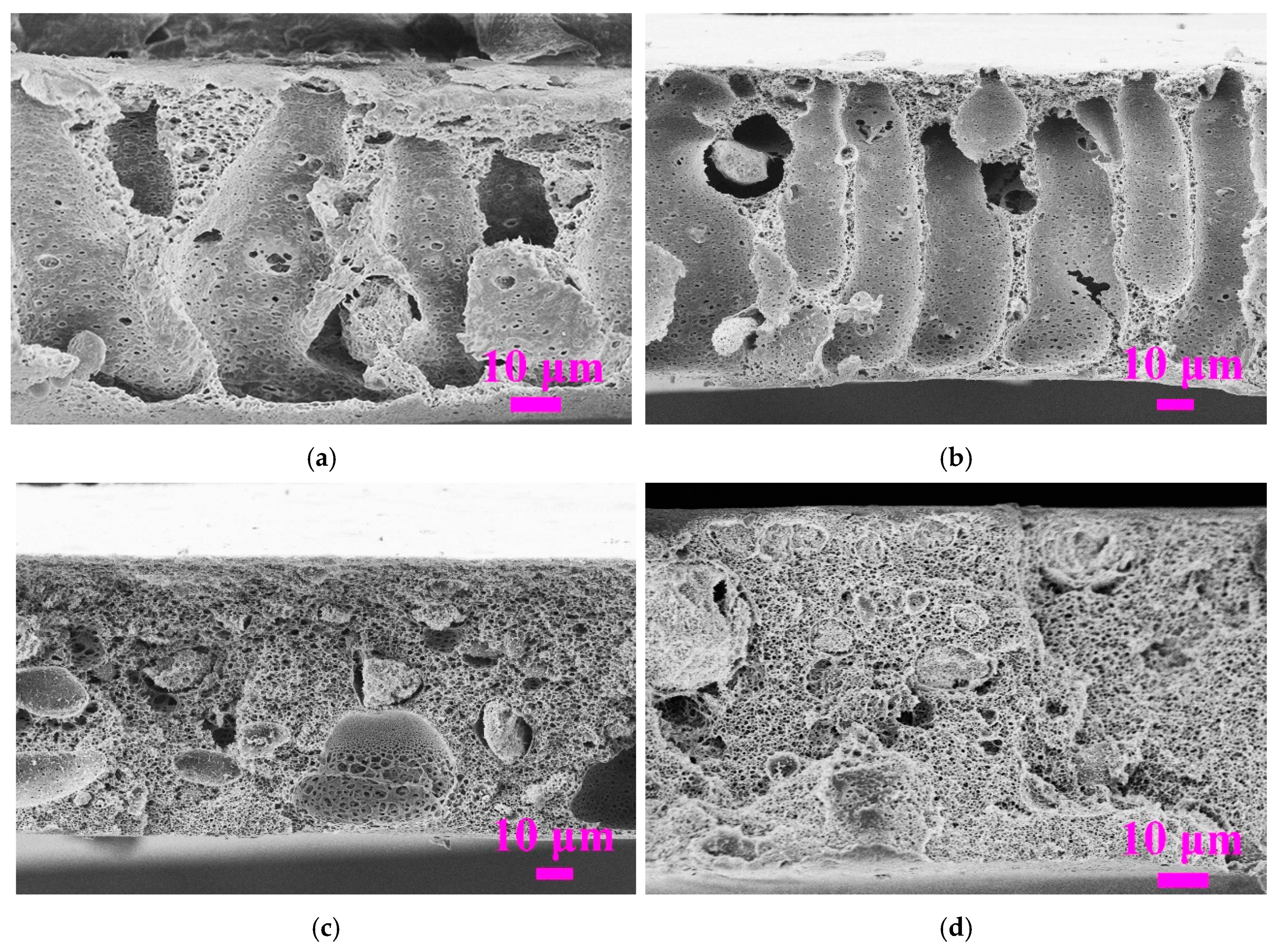
Figure 3.
Effect of the weight ratio of SiO2/PVDF on the morphology of PVDF/SiO2 composite membranes. (a) SiO2:PVDF = 0 (dope solution M0); (b) SiO2:PVDF = 1:30 (dope solution M1); (c) SiO2:PVDF = 1:15 (dope solution M2); (d) SiO2:PVDF = 1:10 (dope solution M3).
Figure 3.
Effect of the weight ratio of SiO2/PVDF on the morphology of PVDF/SiO2 composite membranes. (a) SiO2:PVDF = 0 (dope solution M0); (b) SiO2:PVDF = 1:30 (dope solution M1); (c) SiO2:PVDF = 1:15 (dope solution M2); (d) SiO2:PVDF = 1:10 (dope solution M3).
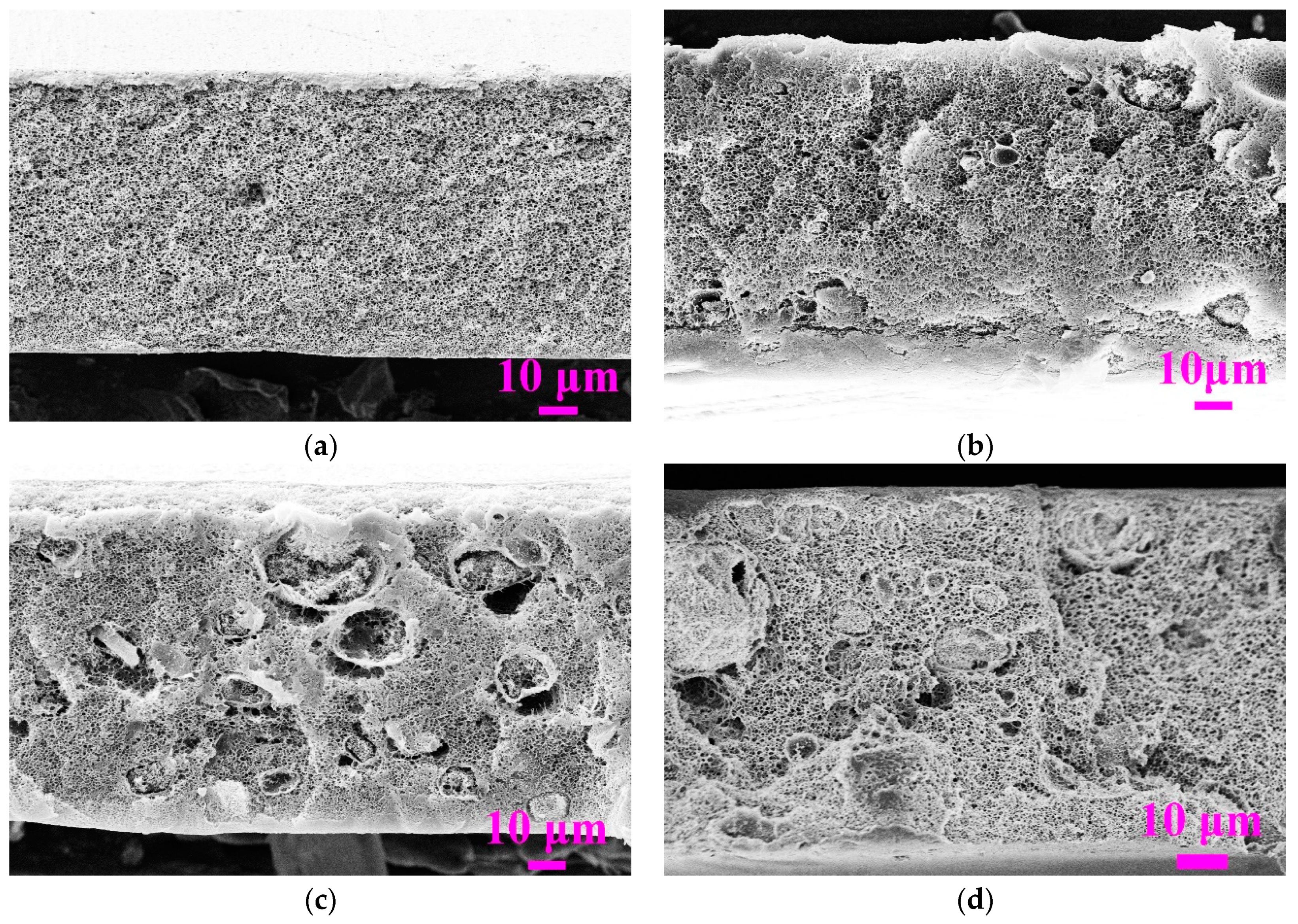
Figure 4.
Effect of coagulation temperature on the morphology of PVDF/SiO2 composite membranes. (a) 30 °C. (b) 50 °C. (c) 70 °C. (d) 90 °C.
Figure 4.
Effect of coagulation temperature on the morphology of PVDF/SiO2 composite membranes. (a) 30 °C. (b) 50 °C. (c) 70 °C. (d) 90 °C.


Figure 5.
Effect of coagulation temperature on normalized light transmittances of nascent membranes cast with the dope solutions of M0 and M3.
Figure 5.
Effect of coagulation temperature on normalized light transmittances of nascent membranes cast with the dope solutions of M0 and M3.
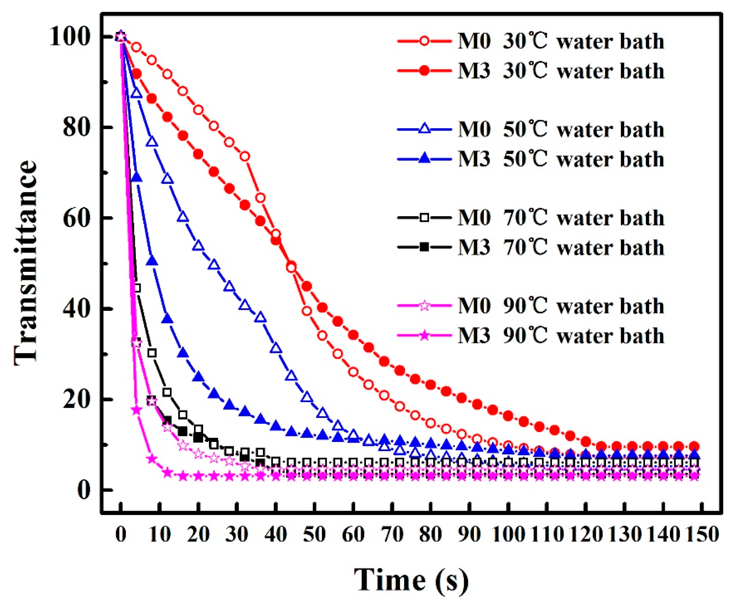
Figure 6.
Effect of coagulation temperature on the mechanical properties of the PVDF/SiO2 composite membranes.
Figure 6.
Effect of coagulation temperature on the mechanical properties of the PVDF/SiO2 composite membranes.
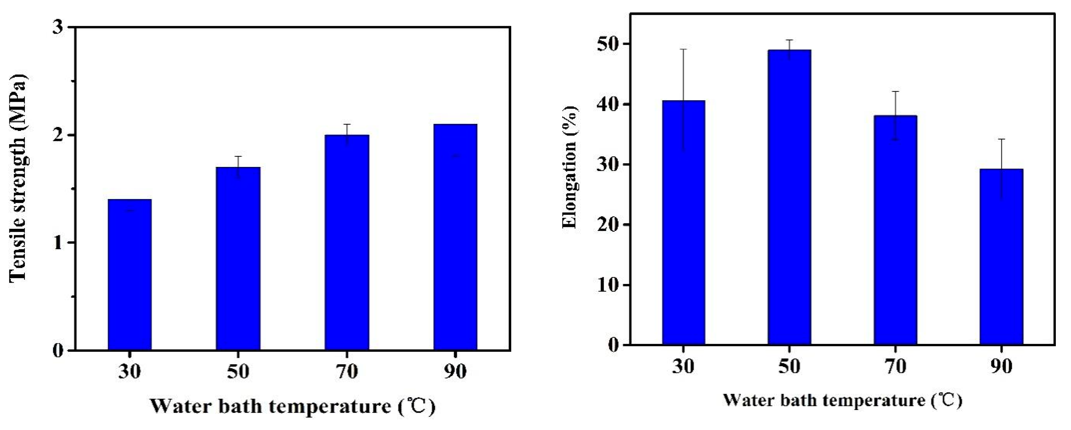
Figure 7.
Separation performance of four membranes T30–T90 at varying coagulation temperature: (a) pure water flux; (b) flux and rejection efficiency with surfactant stabilized emulsion; (c) photographs of original emulsion and permeates obtained with various membranes; (d) size distribution of oil droplets in surfactant-stabilized oil/water emulsion (dope solution: M3; operation pressure: 20 kPa; ambient temperature, testing period: 60 min).

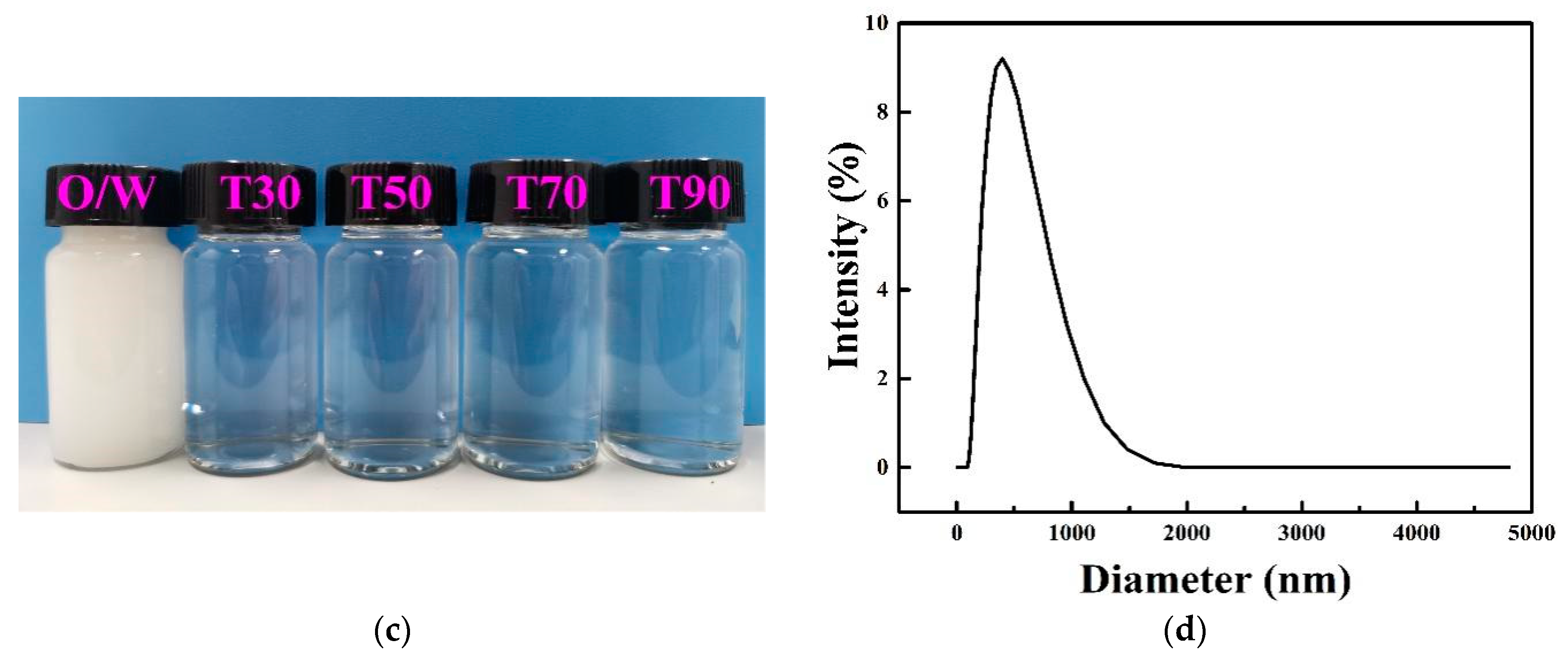
Figure 8.
Oil/water emulsion separation: (a) normalizated water flux during a 3-cycle filtration of oil/water emulsion by the membranes T30, T50, T70, and T90; (b) flux recovery ratio (Frr), total fouling ratio (Rt), reversible fouling ratio (Rr), irreversible fouling ratio (Rir), and Rir/Rt with oil/water emulsion as the foulant after the first cycle; (c) comparison of the normalized water flux of T70 with benchmark B70 during a 3-cycle filtration of oil/water emulsion; (d) comparison of Frr, Rt, Rr, Rir, and Rir/Rt of T70 and B70 after first cycle.


Table 1.
Composition of dope solutions.
| Dope Solution Code | Composition of Dope Solution (wt%) | ||||
|---|---|---|---|---|---|
| PVDF | SiO2 | PVP | DMAc | MgCl2 | |
| M0 | 16 | 0 | 8 | 68.0 | 8 |
| M1 | 16 | 0.53 | 8 | 67.5 | 8 |
| M2 | 16 | 1.07 | 8 | 66.9 | 8 |
| M3 | 16 | 1.6 | 8 | 66.4 | 8 |
| M4 | 14 | 1.4 | 8 | 68.6 | 8 |
| M5 | 12 | 1.2 | 8 | 70.8 | 8 |
| M6 | 10 | 1.0 | 8 | 73.0 | 8 |
Table 2.
Porosity, pore size parameters, and contact angle of the membranes fabricated by dope solution M3 at different coagulation temperatures.
Table 2.
Porosity, pore size parameters, and contact angle of the membranes fabricated by dope solution M3 at different coagulation temperatures.
| Membrane ID | Coagulation Temperature (°C) | Porosity (ε, %) | rmax (μm) | rm (μm) | rmax/rm | Contact Angle (°) |
|---|---|---|---|---|---|---|
| T30 | 30 | 84.8 ± 0.5 | 0.161 ± 0.013 | 0.072 ± 0.014 | 2.2 | 81 ± 2 |
| T50 | 50 | 80.6 ± 0.4 | 0.187 ± 0.014 | 0.101 ± 0.016 | 1.9 | 73 ± 1 |
| T70 | 70 | 79.7 ± 1.1 | 0.186 ± 0.024 | 0.084 ± 0.021 | 2.2 | 74 ± 1 |
| T90 | 90 | 81.4 ± 0.7 | 0.203 ± 0.007 | 0.068 ± 0.014 | 3.0 | 68 ± 2 |
Table 3.
Comparison of the as-developed membrane T70 and membranes from selected literature for oily water purification.
Table 3.
Comparison of the as-developed membrane T70 and membranes from selected literature for oily water purification.
| Membrane Material | Pore Size (μm) | Type of Oil Emulsion | Oil Droplet Diameter (μm) | Permeate Flux (L·m−2·h−1·bar−1 ) | Rejection (%) | Ref. |
|---|---|---|---|---|---|---|
| PVDF/TiO2 | / | Diesel oil (10 g/L) | 1–20 | 382 | 99 | [40] |
| Ceramic (modified) | 0.11 | Soybean oil (0.2 g/L) | 1.09 | 150 | 97.0 | [41] |
| Ceramic (FATP) | 0.6 | Engine oil (2 g/L) | 5 | 209 | 98.7 | [42] |
| PVDF (grafted) | 0.45 | Soybean oil (100 g/L) | 0.7–1.4 | 10 | 99 | [43] |
| Polyimide | 0.16 | Dodecane (5 g/L) | 0.63 | 121 | 86.6 | [44] |
| PVDF/SiO2 (T70) | 0.17 | Soybean oil (5 g/L) | 0.1–1.7 | 413 | 99.4 | This work |
Publisher’s Note: MDPI stays neutral with regard to jurisdictional claims in published maps and institutional affiliations. |
© 2021 by the authors. Licensee MDPI, Basel, Switzerland. This article is an open access article distributed under the terms and conditions of the Creative Commons Attribution (CC BY) license (https://creativecommons.org/licenses/by/4.0/).
Share and Cite
MDPI and ACS Style
Xu, Q.; Chen, Y.; Xiao, T.; Yang, X. A Facile Method to Control Pore Structure of PVDF/SiO2 Composite Membranes for Efficient Oil/Water Purification. Membranes 2021, 11, 803. https://doi.org/10.3390/membranes11110803
AMA Style
Xu Q, Chen Y, Xiao T, Yang X. A Facile Method to Control Pore Structure of PVDF/SiO2 Composite Membranes for Efficient Oil/Water Purification. Membranes. 2021; 11(11):803. https://doi.org/10.3390/membranes11110803
Chicago/Turabian StyleXu, Qianqian, Yuchao Chen, Tonghu Xiao, and Xing Yang. 2021. "A Facile Method to Control Pore Structure of PVDF/SiO2 Composite Membranes for Efficient Oil/Water Purification" Membranes 11, no. 11: 803. https://doi.org/10.3390/membranes11110803
Note that from the first issue of 2016, this journal uses article numbers instead of page numbers. See further details here.