Article

Experimental Study and Optimization of the Organic Rankine Cycle with Pure NovecTM649 and Zeotropic Mixture NovecTM649/HFE7000 as Working Fluid

1
Department LITEN, University Grenoble Alpes, CEA, LITEN, L2ST, 38054 Grenoble, France
2
Department LEGI, University Grenoble Alpes, CNRS, LEGI, 38000 Grenoble, France
*
Author to whom correspondence should be addressed.
Appl. Sci. 2019, 9(9), 1865; https://doi.org/10.3390/app9091865
Submission received: 18 April 2019 / Revised: 26 April 2019 / Accepted: 5 May 2019 / Published: 7 May 2019
(This article belongs to the Special Issue Organic Rankine Cycle Systems for Waste-Heat Recovery)

Abstract

:

Featured Application

This work shows the interest in new low Global Warming Potential replacement fluids for Organic Rankine Cycles and suggests the use of zeotropic mixtures to improve Organic Rankine Cycle systems.

Abstract

The Organic Rankine Cycle (ORC) is widely used in industry to recover low-grade heat. Recently, some research on the ORC has focused on micro power production with new low global warming potential (GWP) replacement working fluids. However, few experimental tests have investigated the real performance level of this system in comparison with the ORC using classical fluids. This study concerns the experimental analysis and comparison of a compact (0.25 m3) Organic Rankine Cycle installation using as working fluids the NovecTM649 pure fluid and a zeotropic mixture composed of 80% NovecTM649 and 20% HFE7000 (mass composition) for low-grade waste heat conversion to produce low power. The purpose of this experimental test bench is to study replacement fluids and characterize them as possible replacement fluid candidates for an existing ORC system. The ORC performance with the pure fluid, which is the media specifically designed for this conversion system, shows good results as a replacement fluid in comparison with the ORC literature. The use of the mixture leads to a 10% increase in the global performance of the installation. Concerning the expansion component, an axial micro-turbine, its performance is only slightly affected by the use of the mixture. These results show that zeotropic mixtures can be used as an adjustment parameter for a given ORC installation and thus allow for the best use of the heat source available to produce electricity.

1. Introduction

The Organic Rankine Cycle (ORC) has been used since the 19th century to produce mechanical and electrical energy from a thermal energy source. The thermal energy can result from various sources, such as geothermal, solar, biomass combustion, waste heat recovery from industrial processes, or internal combustion engines. The power production levels of commercial ORCs range from 10 kW to 10 MW for a heat source temperature that varies between 100 °C and 300 °C. However, these temperatures and power ranges tend to be extended as a result of technological advances in micro combined heat and power (CHP) and heat recovery in the residential and road transport sectors [1,2,3,4,5,6]. Regarding the current energy concern, power production from waste heat recovery needs to be truly investigated. In the industrial sector, the amount of the heat that is rejected is estimated to be 50% of the initial heat load used for industrial processes [7,8]. A significant part of this waste heat could be recovered. For this type of heat source, the largest part of the waste heat is located at temperatures below 200 °C [4,9], which confirms the interest in ORC systems. The corresponding ORC market for low waste heat conversion to low power is important and growing [1,2,4].
Imran et al. [10] highlighted the increase in research on waste heat recovery in the ORC field. Studies are not focused on a particular aspect of this field; there is a broad range, including simulation [11,12] and experimental [13,14] studies, system [15,16] and component [17,18] investigations, and working fluid selection [19,20]. Regarding advances in simulations, Hærvig et al. [21] screened with a genetic optimization algorithm 26 common working fluids for a heat source in the temperature range of 50–280 °C. Critical conditions and the slope of the vapor line were found to be important criteria of optimization parameters for a given heat source temperature. Dickes et al. [22] developed a charge-sensitive model of a 2 kWe recuperative ORC to characterize and optimize the performances of ORC for off-design operation. Regarding the available experimental studies screened thanks to the Landelle et al. [23] database, two working fluids have been principally investigated in the corresponding ORC literature: R-245fa [24,25] and R-123 [26,27]. Galloni et al. [28] and Chang et al. [29] both studied an ORC system with a scroll expander and R-245fa as the working fluid in an ORC system. The heat source is below 100 °C for both studies, and the results lead respectively to a maximum power production of 1.17 kW and 1.56 kW, and maximum thermal efficiencies of 9.28% and 9.43%. Miao et al. [30] investigated R-123 as a working fluid for an ORC with a scroll expander for two different heat source temperatures. The results show that the best performances of the ORC depend on the relevant selected parameter: power production, thermal efficiency, etc. At 140 °C, the highest obtained shaft power output is 2.35 kW and the highest system thermal efficiency is 6.39%. At 160 °C, the highest obtained shaft power output is 3.25 kW and the highest system thermal efficiency is 5.12%. Lei et al. [31], with R-123, studied a different type of expansion component to produce mechanical work and electricity: a single screw expander that eliminated losses under expansion and obtained for the shaft power a maximum value of 8.35 kW and for the thermal ORC efficiency a maximum value of 7.98%. As can be observed in the previously described literature, a scroll-type expander is the most common expansion component used in small-scale ORC systems. However, other types of expansion component have also been studied, including a turbine [32,33], a screw [34,35], a piston [36,37] and a rotary vane [38,39]. Other research topics have also been investigated, such as the impact of ambient temperature on the system [40] or the type of thermodynamic cycle (subcritical, supercritical) followed by the working fluid in the ORC [41].
Currently, most ORC systems use the classical working fluids. However, environmental concerns on global warming and ozone destruction impact ORC systems, and are linked to the evolution of refrigerant fluid legislation, the Montreal Protocol, the Kyoto Protocol, and the Kigali Agreement [42,43]. Hence, the use of and research on less-polluting and replacement fluids has tended to increase [44,45,46]. Two types of low global warming potential (GWP) working fluids have appeared, namely Hydrofluoroolefin (HFO) [44,47] and Hydrofluoroether (HFE) [45,48], as potential replacement working fluids for the ORC. The interest in these fluids issues from their null ozone depletion potential (ODP) and their low or very low GWP. The low-GWP fluid HFO-1336mzz is an interesting R-245fa replacement fluid, and the two isomers (Z) and (E) of this fluid show similar performances to the R-245fa. Navaro-Esbri et al. [49] studied HFO-1336mzz-Z, and the experimental results obtained with this fluid in comparison to those obtained with the R-245fa for the same ORC show a similar range of net electrical efficiency. Yang et al. [50] studied the other isomer HFO-1336mzz-E, and obtained similar performances trends as those obtained with R-245fa. Another HFO replacement fluid for the R-245fa is the HFO-1234 [50,51]; for this HFO fluid, the two isomers (ze) and (yf) present comparable performances with R-245fa. However, the operating conditions and parameters, and the experimental facility of an ORC system, are important, as illustrated with the performances of HFO-1234. Although similar performances for these two HFO fluids ((ze) and (yf)) to R-245fa were obtained in studies [50] and [51], slightly higher performance than R-245fa was obtained in the study of Yang et al. [50] and slightly lower performance in the study of Cambi et al. [51]. Cambi et al. [51] also demonstrated the good performances of HFO-1234ze and HFO-1234yf in comparison with the HFC fluid R-134a. The second low-GWP type of working fluids, HFE fluids, are described as attractive ORC fluids; however, just a few theoretical and experimental investigations have been done to date. Qiu et al. [52] presented a biomass-fired, ORC-based micro-CHP for domestic applications with HFE7000 as the working fluid for the ORC system. Their preliminary results, lower than previous expected simulations, highlight the interest of this type of global conversion system for domestic use on a small scale of heat source temperature and power production. Jradi et al. [53], Kaczmarczyk et al. [54], and Pu et al. [55] investigated HFE7100 in a small ORC with, respectively, a scroll expander, a radial turbine, and an axial turbine. For each of them, the global ORC performance results are moderate but show the sustainability of this working fluid. Two other HFE fluids [56], HFE245fa2 and HFE245cb2, present interesting ORC performances; however, their GWP is higher than HFE7000 and HFE7100 and closest to the classical HFC fluid R-245fa (GWPR-245fa = 1030). However, HFO fluids represent a potential problem due to their atmospheric decomposition to trifluoroacetic acid (TFA). Concerning HFE fluids, with a lower GWP than HFC fluids, their value remains around 500, which leads us to pay specific attention to their utilization in the close future. In addition to HFO and HFE, Hydrochlorofluoroolefin (HCFO) [50,57] has been investigated. The interest in natural refrigerants as ORC working fluids is making a comeback due to their strong environmental friendly aspect, although their flammable potential remains high [58,59]. Finally, another new low-GWP fluid, NovecTM649, seems to be an interesting working fluid according to the preliminary literature [20,60,61].
As described in the above paragraph, for the low-GWP fluids, although they have an interesting environmental aspect and good performances, these ORC performances in comparison to classical fluids are not always similar or better. This could be an issue in the case of fluid replacement in an existing ORC installation with a necessity to maintain a certain level of performance in electrical production. The intensification of working fluids performances in existing systems is investigated so as to implement low-GWP fluids in existing ORC plants using banned fluids and thus enabling these installations to continue to operate at equivalent levels of performances [2,19,62,63,64]. One expected and investigated way to improve an existing ORC is to implement a zeotropic mixture as the working fluid in the existing system [6,19,62,63,65]. A zeotropic mixture is a blend of two or more pure fluids, with the specificity to have a non-isothermal phase-change at constant pressure, an evaporation step, and a condensation step in the ORC; this in contrast to a pure fluid and an azeotropic mixture, whose change from a liquid state to a gaseous state is, reciprocally, performed at constant temperature and constant pressure. This non-isothermal phase-change, also called the temperature glide, could decrease the temperature difference between the working fluids and the heat source and heat sink and thus decrease the irreversibility in ORC exchangers [62].
The recent interest in zeotropic mixtures for ORC systems has produced a very low number of experimental investigations in comparison to refrigeration and heat pump systems, where mixtures have been widely studied. To the best of the authors’ knowledge, less than 20 experimental studies are available in the current ORC literature, and, consequently, each of them has been implemented in the available database to be clearly compared. Theoretical and simulation analyses of zeotropic mixtures’ impacts in the ORC have provided some trends and assumptions in terms of ORC behaviors and performances. Xiao et al. [66] and Zhai et al. [67] studied the reduction of irreversibility in hot and cold ORC exchangers. They pointed out that the use of zeotropic mixtures could lead to an optimization of the heat and sink sources according to specific operations of an ORC system and improve the exchanger and global installation performances. Zhai et al. [67] and Zhao et al. [68] studied the optimal heat source temperature for a zeotropic mixture. Zhai et al. [67] developed a statistical approach to validate the proper operation of a zeotropic mixture in an ORC with its critical temperature. This expression depends only on the heat source temperature and the evaporation pinch temperature of the optimal pure fluid designed for the same ORC and which is one of the fluids in the mixture. Zhao et al. [68] showed that a zeotropic mixture has an optimal composition according to the temperature heat source, which could be variable if the heat source temperature changes. Deethayat et al. [69] developed a Figure Of Merit (FOM), arising from Kuo et al. [70], which allows for the same ORC performance predictions as the thermal efficiency for an ORC system with only six parameters, while the thermal efficiency in its entire theoretical expression needs 14 parameters. However, the use of a zeotropic mixture needs to be carefully considered due to the possibility of shift [71,72] and fractionating [73], which lead to a variation in the mixture’s composition inside the ORC and could change and decrease the ORC’s performance. Another possible drawback with the use of zeotropic mixtures is the variation of the heat transfer coefficients. This variation could lead to an increase in the required exchangers’ heat transfer area to keep the ORC’s performances comparable to those of pure fluids [62]. The available ORC zeotropic mixture literature deals with blends with only classical fluids or classical and low-GWP fluids to the best of the authors’ knowledge.
From the above survey of the literature, research on low-GWP fluids in the ORC is increasing. However, just a few studies deal with the experimental investigation and optimization of ORC systems with low-GWP fluids. Zeotropic mixtures are a relevant example, because of the lack of studies on a zeotropic mixture with a blend of only low-GWP fluids. This study provides some experimental results on and an analysis of a compact ORC installation using the promising NovecTM649 low-GWP fluid, and a fixed blend of a zeotropic mixture composed of two low-GWP fluids, NovecTM649 and HFE7000, as working fluids.

2. Materials and Methods
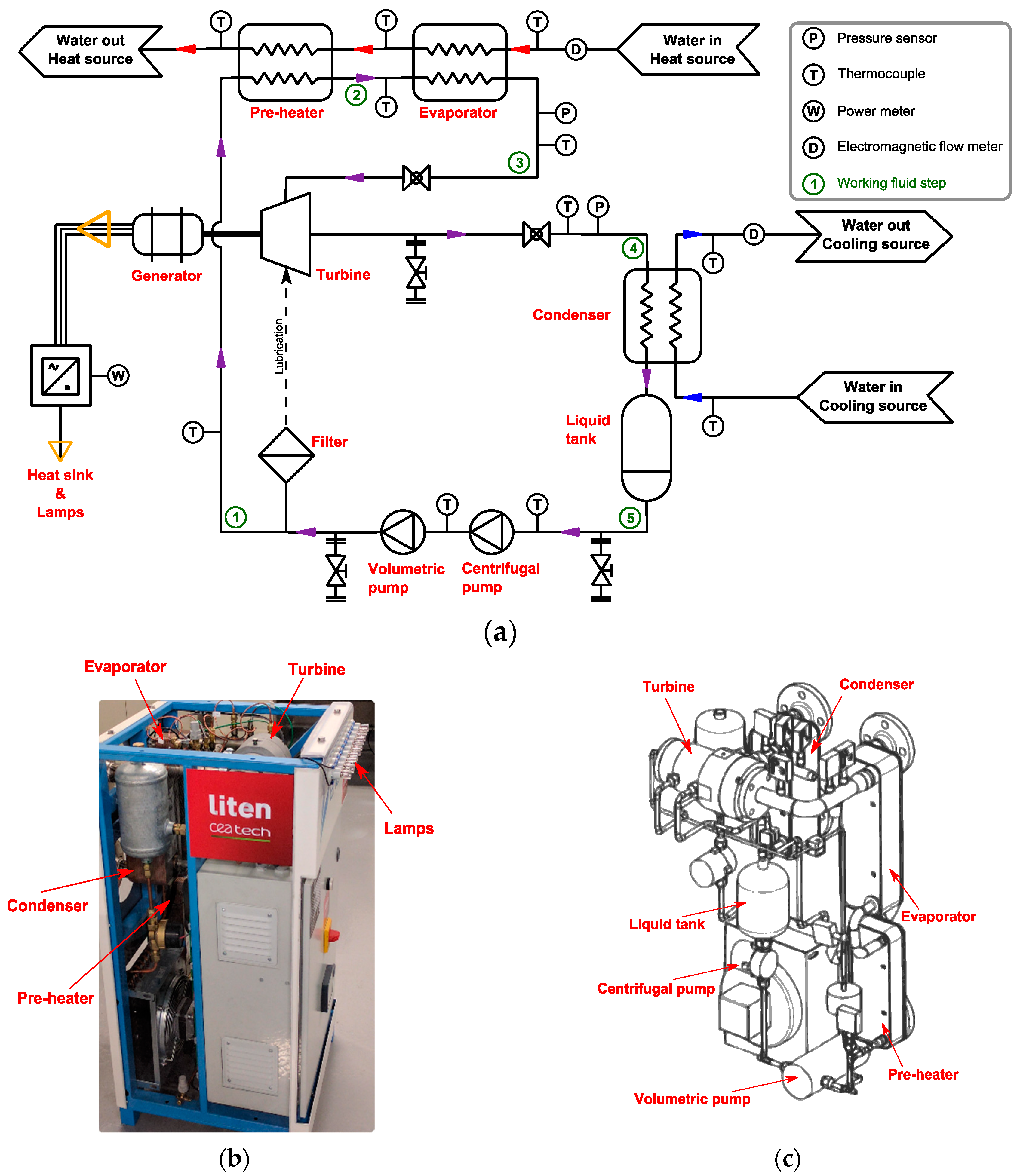
2.1. The ORC System

The Process Flow Diagram (PFD), a picture, and a diagram of the installation are given in Figure 1a–c, respectively. Within the ORC, the working fluid, in its liquid state, passes to the high-pressure level thanks to the volumetric pump. The fluid is then heated, evaporated, and superheated with the hot source through the preheater and evaporator. It is expanded in the turbine, producing mechanical work. At a low pressure, the fluid is cooled, condensed, and sub-cooled by the cold source within the condenser and then pumped again to close the cycle. In order to dissipate the electricity produced at the generator, two elements are used: lamps with a total power of 50 W and a heat sink.
The system includes an axial micro-turbine that was specifically designed for the installation by Enogia Company. This turbine, which was initially designed to operate with the pure fluid NovecTM649, is a single-stage impulse turbine. The lubrication of the bearing system is carried out with the working fluid. An external circuit specific to the generator ensures its cooling to allow for its proper operation. Two pumps ensure the circulation and pressurization of the working fluid in the ORC circuit; the main pump is a diaphragm-positive displacement pump, and the second is a small centrifugal pump to avoid any risk of cavitation within the main pump [74]. Two heat exchangers, a preheater and an evaporator, are placed in series to allow for energy transfer from the heat source. A third heat exchanger, a condenser, allows for the cooling of the working fluid within the cycle. Placed between the condenser and the centrifugal pump, a tank ensures that there is a sufficient level of liquid at the inlet of the centrifugal pump.

2.2. Heating and Cooling Loops

Waste heat is simulated by an electric boiler in which water is pumped and pressurized to achieve a temperature up to 110 °C in the liquid state at the evaporator inlet. A proportional integral derivative (PID) controller is integrated into the boiler to keep the water at a constant temperature at the evaporator inlet. The water flow rate of the heat loop is fixed manually by means of a valve on the boiler bypass circuit.
The cold source corresponds to the laboratory’s industrial water network, which is at a constant temperature close to 13 °C. A manual valve is used to regulate the water flow within the cold loop.
A specific circuit for the generator ensures its cooling to allow for the internal temperature level of the element to be regulated during operation of the installation. This circuit consists of a small centrifugal pump, a liquid tank, and a cooling fan.

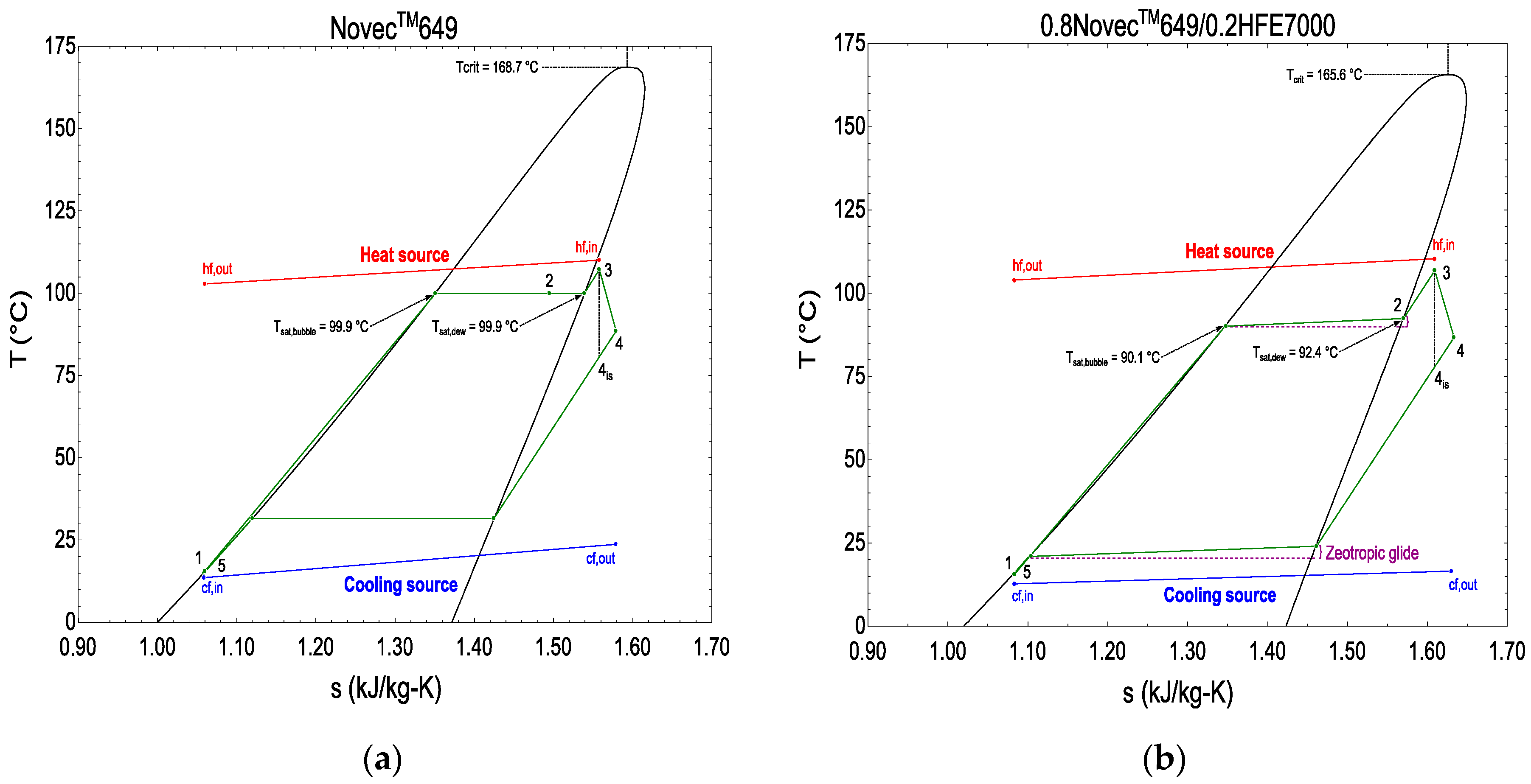
2.3. Working Fluid Selection

The choice of the working fluid is an important parameter in the design of an ORC installation. Several studies have examined the determining criteria for selecting the most suitable fluid for an ORC installation [2,19]. Theoretical efficiency, price, availability, and human and environmental constraints are recurring parameters that are taken into account to select the most appropriate ORC fluid.
In this study, the described system uses two “different” media as the working fluid: a pure fluid and a zeotropic mixture. The pure fluid is the NovecTM649 and the zeotropic mixture is a blend of the previous pure fluid and the pure fluid HFE7000, with a mass proportion of 80% and 20%, respectively, for the mixture.
The two pure fluids are suggested as possible substitutes for HCFC and HFC [75,76], and considered as interesting ORC working fluids [20,56]. The pure fluid NovecTM649 and the mixture are non-toxic, non-flammable, and have a low environmental impact with a null Ozone Depletion Potential (ODP = 0) and a low Global Warming Potential (GWPNovecTM649 = 1, GWPNovecTM649/HFE7000 = 107) as a greenhouse gas. The pure fluid and the obtained mixture are dry fluids, which provide two significant advantages for the installation: it is not necessary to overheat the steam to avoid the formation of droplets within the turbine, the working fluids being in the dry steam state throughout the expansion stage; this results in a lower minimum hot source temperature compared to the case requiring overheating. Due to the low operating pressures (less than 6 bars), the addition of specific and expensive high-pressure protections is not necessary.
The studied zeotropic mixture has been selected as a blend of NovecTM649 and HFE7000. Different aspects led to the selection of these two pure fluids for the mixture’s composition. Some environmental, thermodynamic, and operating interests have already been discussed. Other important criteria guided the fluids’ selection. The first criterion was to keep the designed ORC pure fluid, the NovecTM649, as a part of the mixture due to the very good environmental aspect and the good performance suggested in the literature and obtained with preliminary simulations. The second criterion was to implement only low-GWP fluids inside the ORC to search for a solution regarding environmental and replacement fluids. The third criterion was that a zeotropic mixture is not possible between all existing fluids and the blend of NovecTM649 and HFE7000 allows for the creation of this type of specific mixture. The last criterion, but not the least, is the materials’ chemical compatibility between the fluid properties and the ORC component materials. The specific mass composition (80%/20%) of the mixture is one of the test compositions of the zeotropic mixture that is currently implemented and investigated inside the ORC. This composition is analyzed in this paper because of the interesting results obtained with it and also to study the ORC’s behavior with gradual implementation of HFE7000 in the working fluid’s composition. The main properties of NovecTM649, HFE7000, and NovecTM649/HFE7000 are listed in Table 1.

2.4. Instrumentation

All sensors used for measurements and data acquisitions are shown in the PFD of the installation in Figure 1a. The characteristics of the measurement devices are listed in Table 2.
The working fluid and the heat source and cooling source loops are equipped with Type-K thermocouples to measure temperatures between the various components.
The working fluid circuit is equipped with absolute pressure sensors (APS) at the turbine inlet and outlet to measure the two pressure stages within the installation.
Volumetric flow rate measurements of hot and cold circuits were performed using electromagnetic flow meters (EFMs). The mass flow rate of the working fluid is determined by the energy balance at the condenser of the experimental installation.
The electrical power produced at the turbine was measured by means of a wattmeter.

3. Data Processing

3.1. Experimental Investigation

During the tests, various experimental parameters can be modified, such as the temperature of the heat source, the volumetric flow rate of the hot and cold circuits, or the working fluid flow rate inside the ORC loop, in order to study their impacts on the installation and its performance. An important number of experimental tests has been carried out: 27 with the pure fluid and 46 with the zeotropic mixture. The optimization goal that was pursued during the experimental tests was to achieve the highest production of electricity at the generator.
In a first comparative approach of this ORC installation to the pure and mixed fluid, this study focuses on the impacts of the change in working fluid on the overall performances of the ORC and turbine.
The main installation parameters and their range of variation imposed on the system during the experimental tests are presented in Table 3.

3.2. Thermodynamic Investigation

The study of the ORC installation, based on experimental data, was carried out using a zero-dimensional (0D) model, by solving energy balances on components and the global system, developed with EES software [77]. A coupling was carried out with the REFPROP v9.1 software [78] to allow for the implementation of thermodynamic properties in the mixture and the pure fluid. These properties result from Helmholtz’s model adapted for the considered fluids [79,80].
According to the theory of uncertainties propagation, the measurement uncertainties for the calculated output variables of the model were calculated using the root-sum-square method. The uncertainty UY of the variable Y was calculated as a function of the uncertainties UXi for each measured variable Xi, as defined in Equation (1).
U Y = i ( Y X i ) 2 · U X i 2

3.2.1. Performances Analysis and Calculation

The performances of this ORC, with the pure fluid and the zeotropic mixture, were screened considering two different aspects: on the one hand, the expansion component; and on the other hand, the performances of the overall ORC system.
The turbine performances, which were analyzed according to the variation in the pressure ratio as defined by Equation (2), were studied according to two different approaches: firstly, with a dimensionless parameter of the turbine as defined by Equation (3); and secondly, with the overall electrical efficiency of the turbine, which includes the expansion element and the generator as defined by Equation (4).
π t u r =   P i n , w f , t u r P o u t , w f , t u r
=   m ˙ w f S i n , t u r · ρ 0 , i n , t u r · c 0 , i n , t u r · ( 2 γ + 1 ) γ + 1 2 · ( γ 1 )
η t u r =   W ˙ e l , t u r W ˙ i s , t u r = W ˙ e l , t u r m ˙ w f · ( h i n , w f , t u r h i s , w f , t u r )
Regarding the dimensionless parameter Ᾱ in Equation (3)’s definition, the polytropic coefficient is involved. To be more realistic to the real transformation and not to consider the pure fluid or the mixture as a perfect gas, the equivalent γ model was used, which is supposed to be an accurate model for dense gas. This model is quite similar to the ideal one, with the difference that the gas goes through a polytropic transformation, assuming the relationship defined in Equation (5):
P i n , w f , t u r ρ i n , w f , t u r γ = P o u t , w f , t u r ρ o u t , w f , t u r γ
The polytropic coefficient, whose value can be less than 1, is evaluated by exploiting the linearity of Equation (5). Thanks to this definition, the polytropic coefficient is obtained for the experimental data, is expressed as the logarithmic relationship l o g P i n P o u t =   γ · l o g ρ i n ρ o u t , and treated as the slope of the linear regression. Figure 2a,b illustrate and confirm this interpretation.
The overall electrical turbine efficiency, corresponding to the highest electrical gross production obtained during the experimental tests, is also compared with the other expansion technologies according to the available literature, for the power production range of 1–10 kW [23].
To analyze the overall performances of the installation, the thermal efficiency of the ORC, as defined by Equation (6), and the second law efficiency of the ORC, as defined by Equations (7) and (8), are studied according to the electricity production. Two comparisons of the tests conducted in pure fluid and mixture are presented. The first one covers all the tests, and the second one compares the pure fluid tests with the mixture tests with the same operating parameters.
η t h , n e t =   W ˙ e l , t u r W ˙ e l , p s Q ˙ h e a t = W ˙ e l , t u r W ˙ e l , p s m ˙ h f · ( h i n , h f , e v a p h o u t , h f , p r e )
η I I , n e t =   W ˙ e l , t u r W ˙ e l , p s E ˙ i n , h f , e v a p E ˙ o u t ,   h f , p r e
E ˙ x = m ˙ x · ( h x h r e f T r e f · ( s x s r e f ) )
As with the turbine, the performances of the ORC are compared with the literature data. To be analyzed with the available data, the ORC performances are taken as their gross efficiencies.
The influence of the variation in the high pressure of the cycle with the mixture is also studied.

3.2.2. Mass Flow Rate Reconciliation

Due to the constraints on the architecture of the ORC prototype, the fluid flow rate is indirectly accessible: it is calculated using the energy balance and carried out at the condenser, as defined by Equation (9).
m ˙ w f = m ˙ c f · ( h o u t , c f , c o n d h i n , c f , c o n d ) + Q ˙ l o s s e s , c o n d ( h i n , w f , c o n d h o u t , w f , c o n d )
A distribution of the heat losses between the hot and cold sources was, therefore, determined when the ORC installation was commissioned. This losses distribution, statistically adjusted during the experimental tests, made it possible to complete the 0D model simulation of the system.

4. Results and Discussion

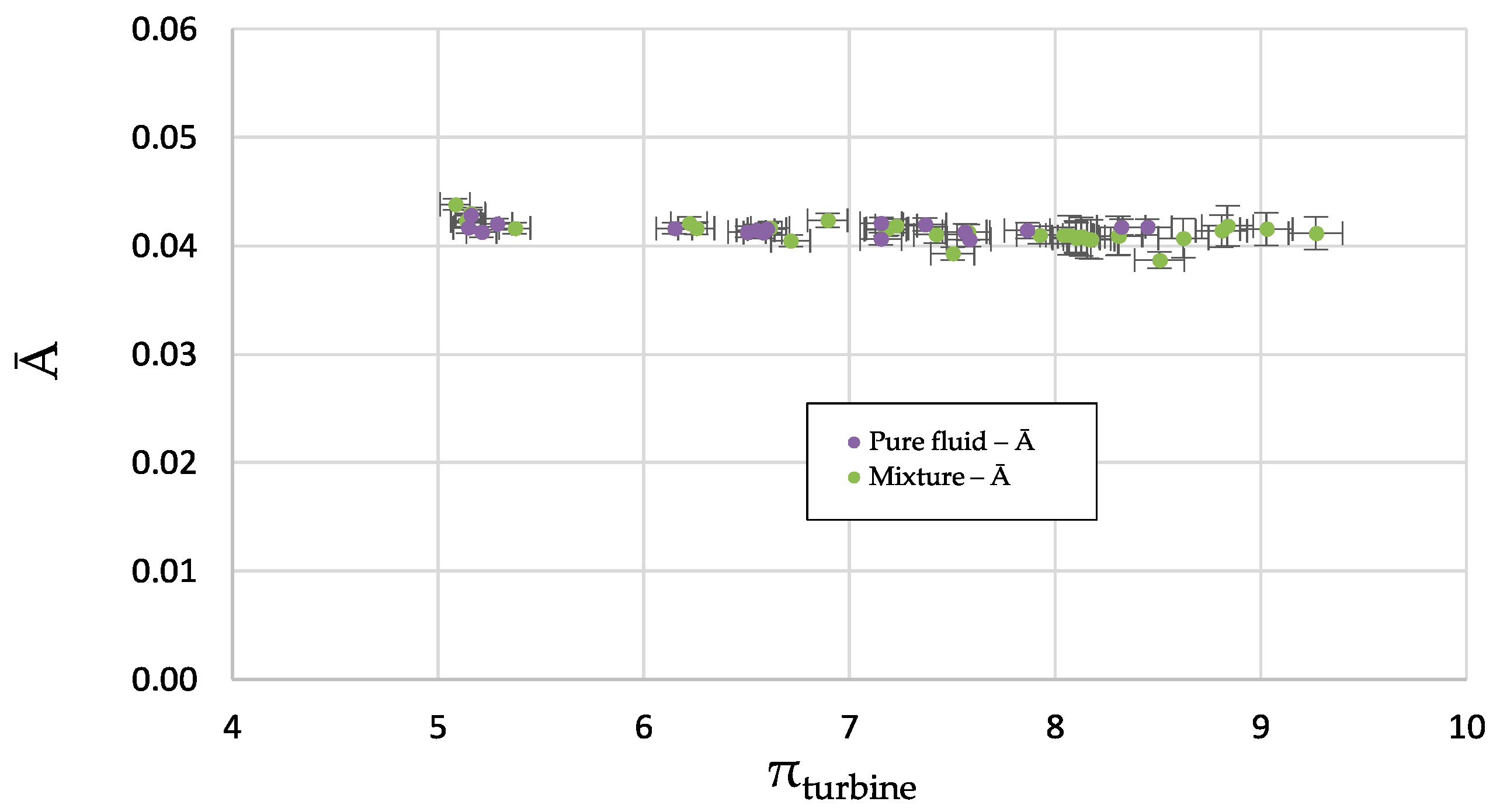
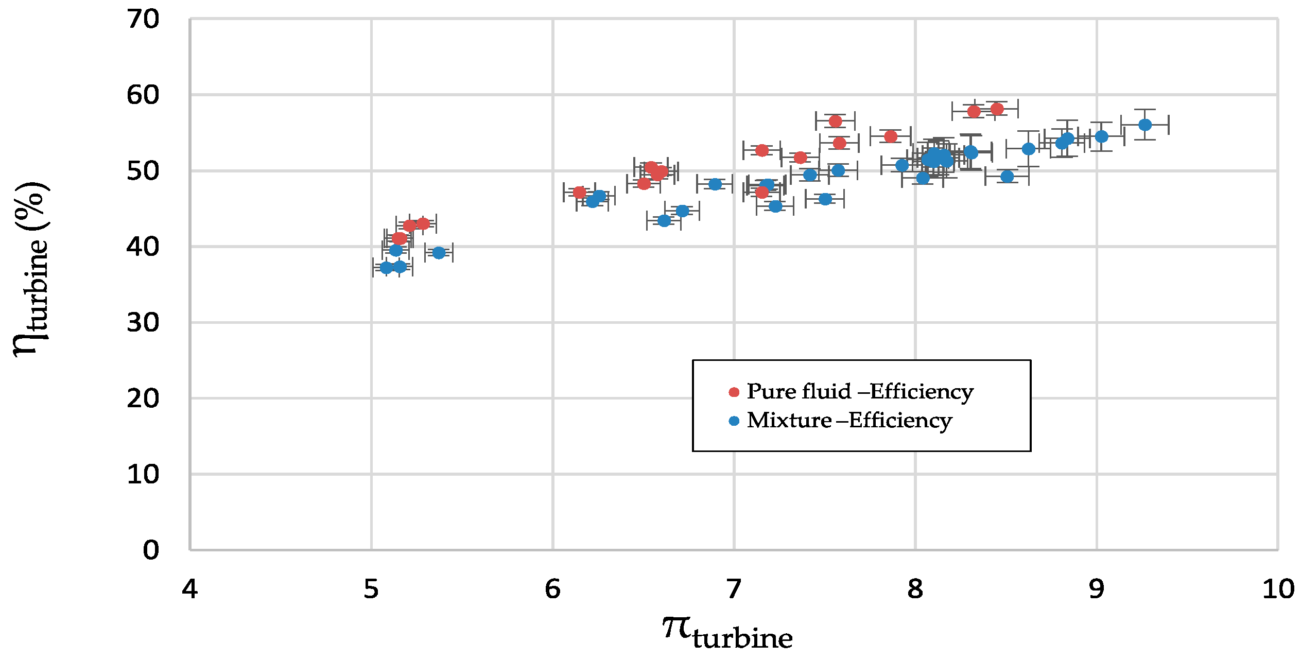
4.1. Turbine Performances

The axial micro-turbine has been designed to work with pure NovecTM649 fluid. In order to study the impact generated by the use of the mixture NovecTM649/HFE7000 on the operation of the expansion element, the dimensionless parameter Ᾱ was calculated in both cases (mixture and pure fluid) as a function of the pressure ratio. This value corresponds to the normalized blade throat area (A*/A0), which represents an intrinsic value of the expansion component (see [81] for theoretical details on the compressible and isentropic flows of real gases).
Due to the conception of the expansion element, the dimensionless parameter Ᾱ is expected to be a constant value for the pure fluid that the turbine was initially designed for. The behavior of the pure fluid on the turbine, represented with purple data in Figure 3, is found, as expected, to be constant, which first confirms the accurate functioning of this element.
In the case of the mixture, the value of Ᾱ is identical to the one for pure fluid. This result, therefore, experimentally confirms that the operation of the turbine is not affected by the change in working fluid, provided that the physical dimensionless parameter (Ᾱ) is considered to be relevant and generalized to real gases.
The overall electrical efficiency of the turbine, shown in Figure 4 on the right ordinate, varies in the same way as the mixture and with the pure fluid, confirming the suitable operation of the expansion component with the mixture. There is a slight decrease of 10% in the value of the efficiency in the case of the zeotropic mixture: this difference can be attributed to the evolution of the mixture’s thermodynamic properties at the turbine inlet compared to those in pure fluid.
During the experiment, the turbine reached, respectively for the pure NovecTM649 and the zeotropic mixture NovecTM649/HFE7000, a maximum electrical gross production of 0.715 kW ± 2 W and 0.703 kW ± 2 W. At these specific points, the isentropic efficiencies of the expansion component are found to be respectively 61.4% and 61.5%. With these isentropic efficiencies, the expansion component is ranked at the average level of the expansion devices in the 1–10 kW power production range, in comparison to the available experimental literature [23], to the best of our knowledge.
For the overall electrical efficiency of the turbine, the values are found to be 58.2% for the pure fluid and 56% for the mixture. These values, replaced within the work of Landelle et al. [82] and described in Figure 5, rank the present turbine among the most efficient for this type of technology. Compared to other types of technologies, for a power production close to 1 kW, the turbine is very interesting because its performances are comparable to that of the Scroll technology, which is the most widespread technology in small power ORCs as observed in Figure 5. The energy conversion at the generator level is very efficient; therefore, the best way to further increase the overall efficiency of the turbine is to improve the expansion element itself and, thus, increase its isentropic efficiency.

4.2. ORC Performances

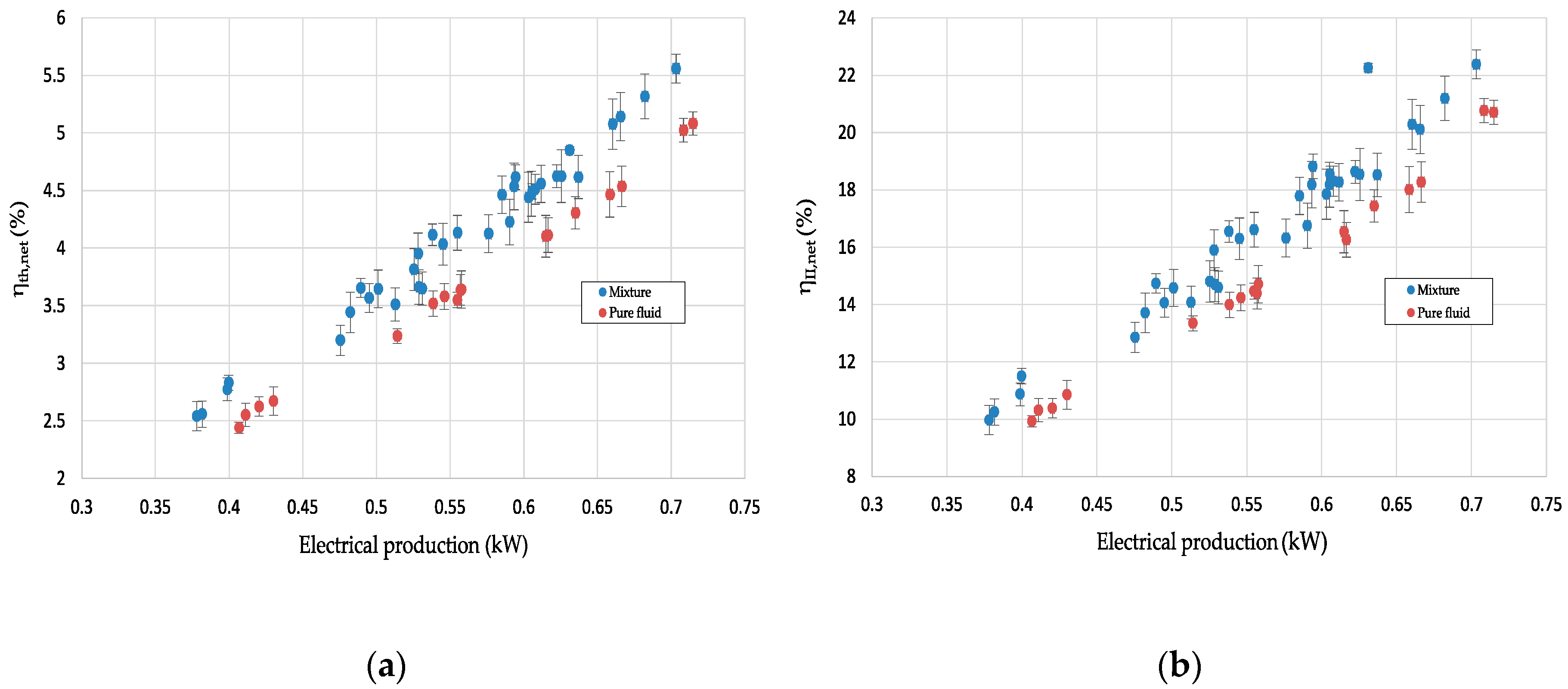
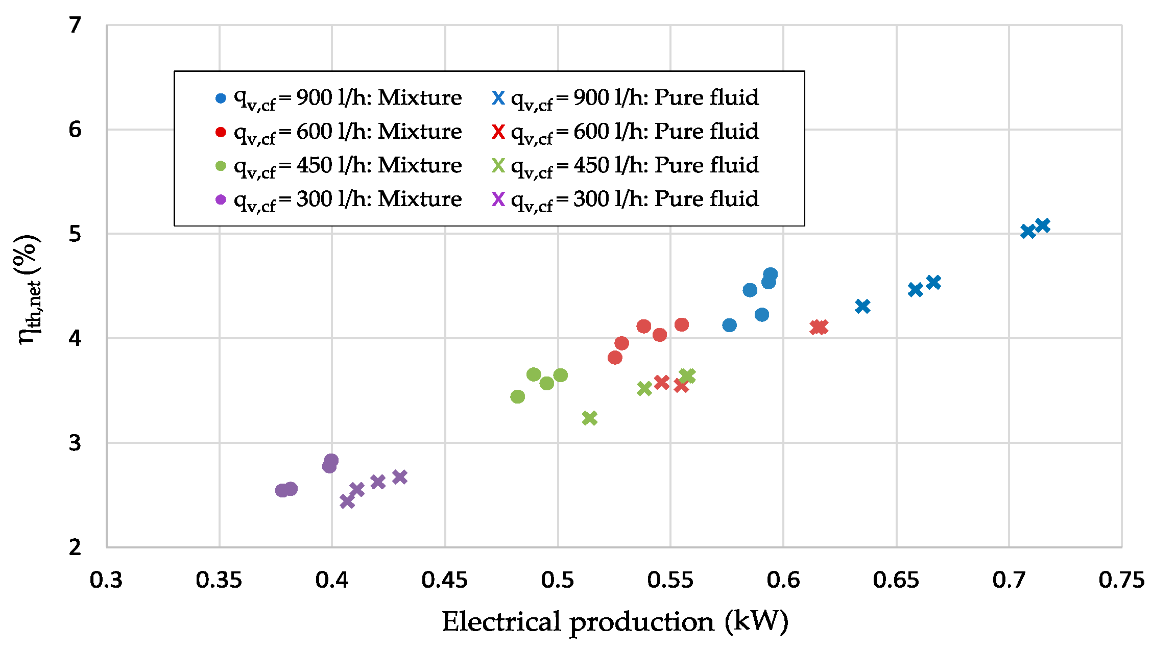
4.2.1. Pure Fluid and Mixture Comparison

During the experimental tests conducted in the mixture on the ORC and compared with the pure fluid tests, for the range of parameter variation as defined in Section 3.1, an increase in the net thermal efficiency of the overall system is observed as shown in Figure 6a. This increase in performance is in the order of 10% for an equivalent production of electricity. To complete the all-tests comparison, the second law efficiency was also studied to evaluate more specifically the conversion of the useful part of the heat source. In Figure 6b, the same increasing trend with the mixture can be identified, which confirms the interest brought to light with the thermal efficiency analysis.
In the case of a comparison with all of the isoparameters, i.e., identical temperatures and flows of hot and cold sources for both the pure fluid and the mixture, the net thermal efficiency is identical and the power produced in the case of the mixture is reduced by 10% (see Figure 7).
The two previous analyses of the results obtained in the experimental tests seem to be contradictory as to the interest of using a mixture as a working fluid within an ORC. However, when using an Organic Rankine Cycle, the aim is to transform thermal energy, called degraded energy, from the heat source, into electrical energy, called noble energy. This type of technology, therefore, seeks to make the best use of the available thermal energy source, and, therefore, to obtain the highest possible thermal efficiency to produce the greatest amount of electricity. The results presented in Figure 6a,b confirm the interest in using fluid mixtures to increase the performances of an ORC installation. The results presented in Figure 7 highlight some of the limitations that can be achieved when using mixtures. Indeed, according to the isoparameters, the mixture is more efficient than the pure fluid for a given range of parameters and amount of electricity production. In this defined range, the zeotropic mixture will, therefore, allow for a better use of the heat source.

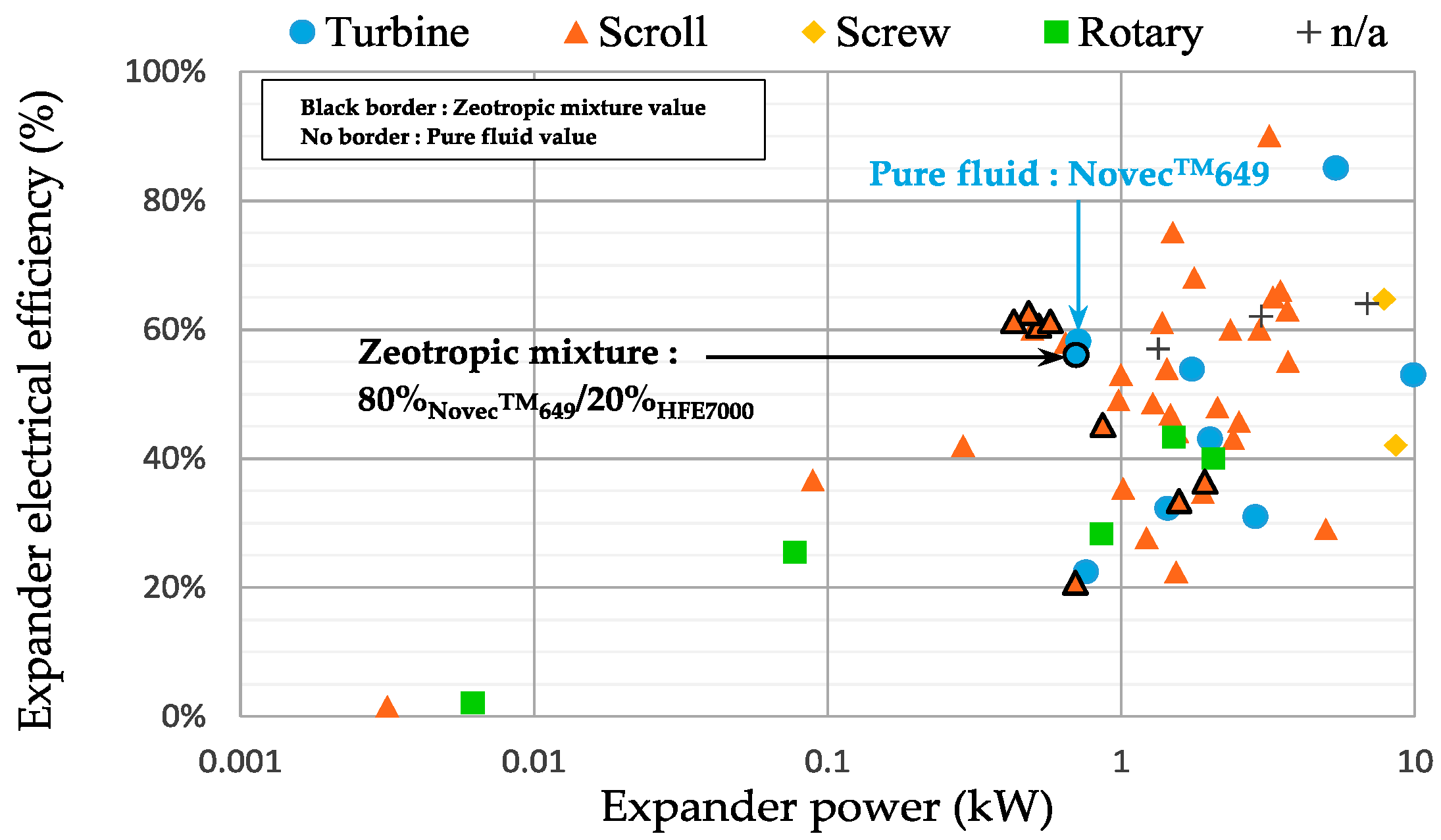
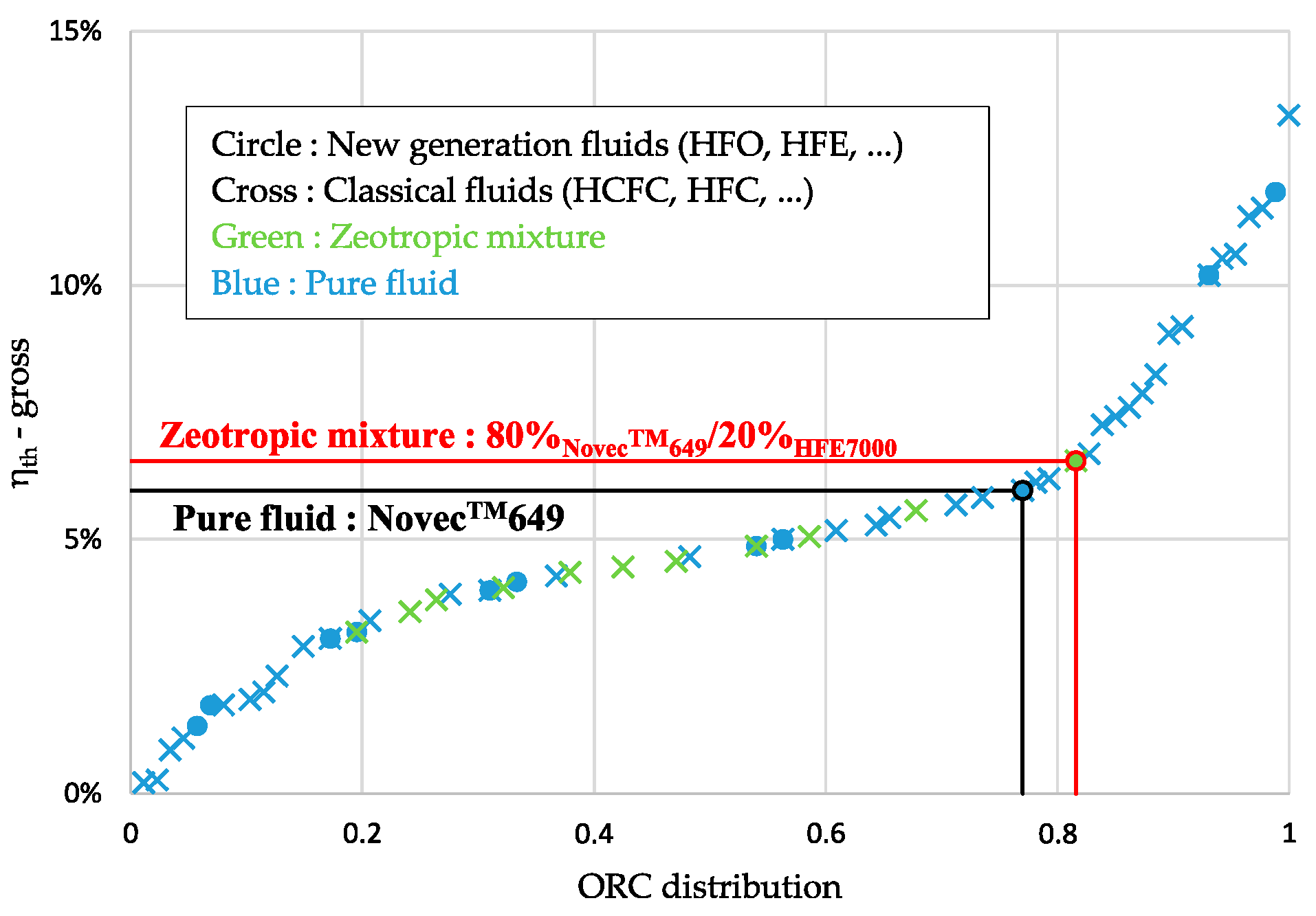
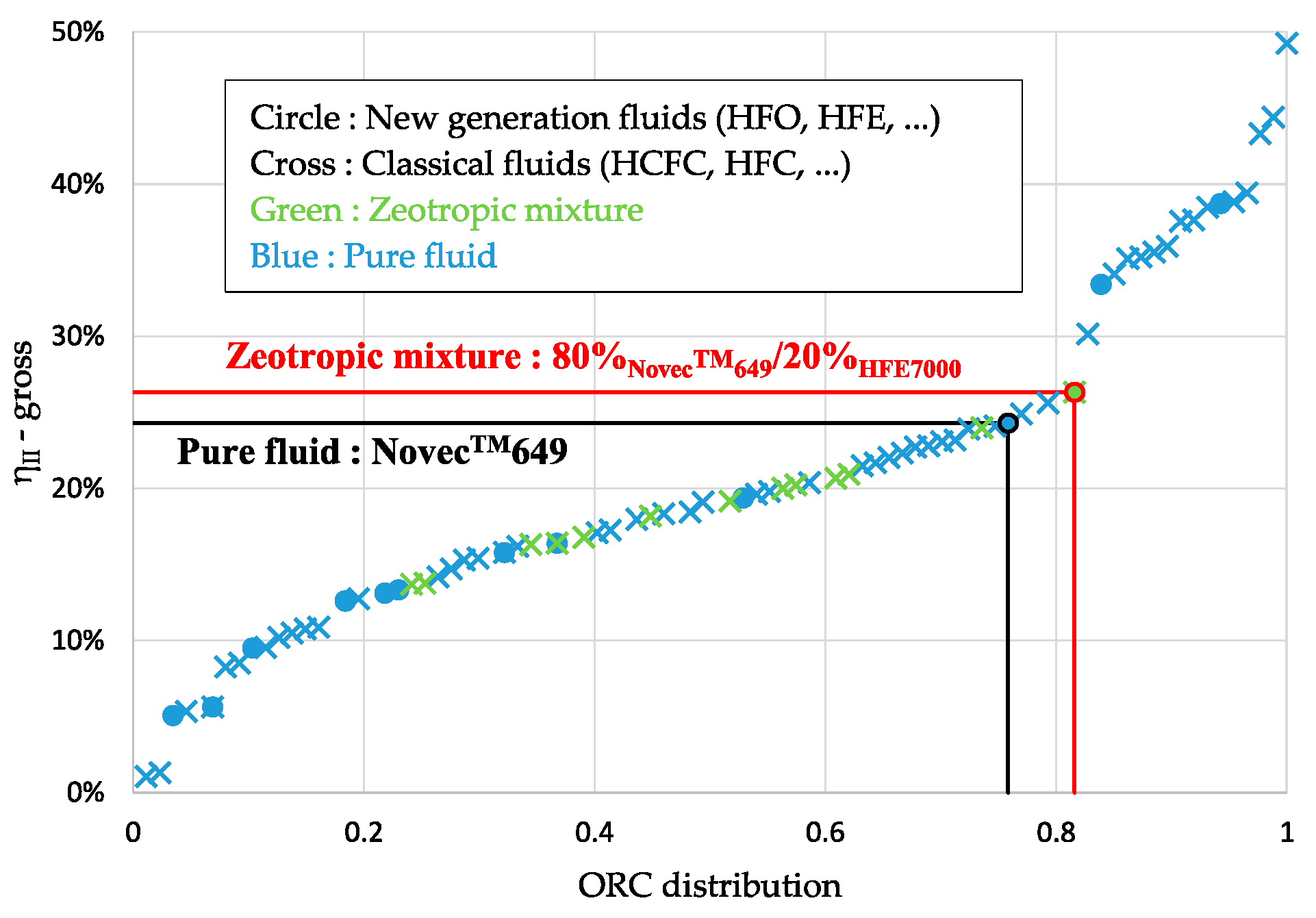
4.2.2. ORC Literature Comparison

The present installation was analyzed in terms of global ORC performances regarding its thermal efficiency and its second law efficiency. To perform an accurate analysis in comparison with other ORC installations and working fluids, the best operating point of the ORC in pure NovecTM649 and the zeotropic mixture NovecTM649/HFE7000 were compared with those in the available experimental ORC literature database [23].
The global ORC performances have reached respectively for the pure fluid and the mixture the value of 5% and 5.6% for the net thermal efficiency, and the value of 20.8% and 22.4% for the net second law efficiency. These efficiencies refer to the experimental points with the highest power production at the expander outlet mentioned in the previous Section 4.1. To carry out the broadest comparison possible with the literature, efficiencies were screened as their gross efficiencies.
The other calculated data for the optimized highest points are listed in Table 4. The T-s diagrams of the ORC for these two points are also presented in Figure 8. It can be noticed that, for the zeotropic mixture, the highest point corresponds to a good agreement between the evolution of the zeotropic glide and the evolution of the sink source temperature.
Extracted from the literature database, experimental ORCs were arranged from the lowest to the highest gross thermal efficiency or gross second law efficiency by their cumulative distribution function for the selected power range up to 10 kW and heat source temperature lower than 200 °C. This ordering method allows us to rank the ORC investigated in this study and to compare its performances to those of other installations. Figure 9 and Figure 10 show the distribution of experimental ORCs.
The present experimental test bench has a gross thermal efficiency of 6% for the NovecTM649 and 6.5% for the NovecTM649/HFE7000. These results allow us to rank the current ORC among the top 20% of the most efficient experimental installations (with an ORC distribution of around 0.8). This rating shows the potential of NovecTM649 and the zeotropic mixture NovecTM649/HFE7000 as pertinent fluid candidates to replace classical HFC or HCFC working fluids in comparison to the other new-generation fluids as observed in Figure 9.
To achieve a full comparison of the present installation and avoid any heat source temperature impacts on the ORCs performances ranking, a second law efficiency comparison was also done. With a gross second law efficiency of 24.3% for NovecTM649 and 26.3% for NovecTM649/HFE7000, the current ORC still ranked in the top 20% of the ORC installation performances as described in Figure 10, which confirms the previous discussion on the interest in these new-generation pure and mixed fluids.
The significant increase in efficiency values for the ORC distribution between 0.8 and 1 comes from the level of electrical power production at their expander. Indeed, these ORCs are mostly producing “high” power close to 10 kW, which leads to a size factor on the global performances of the installations.

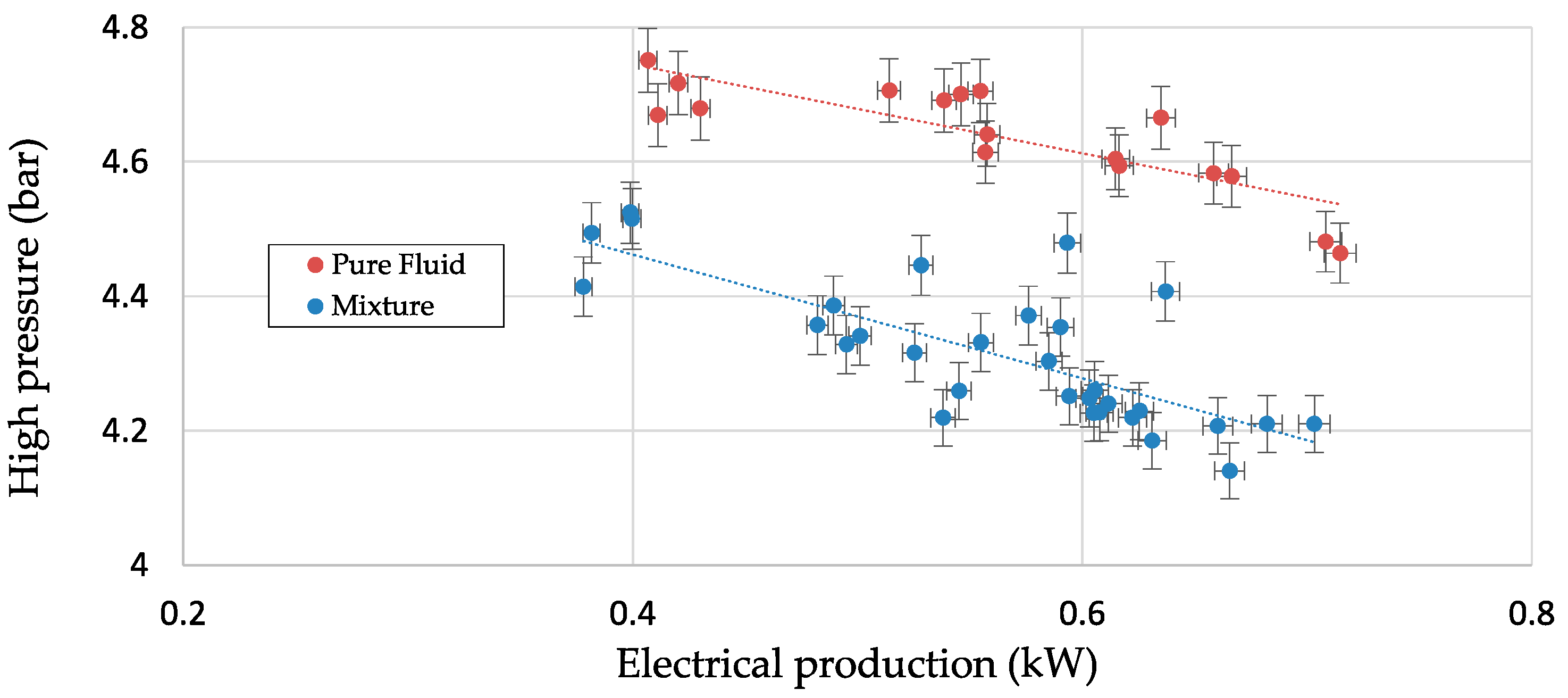
4.2.3. Cycle High Pressure

The high pressure of the cycle, an important parameter of an ORC installation, is also impacted when using a zeotropic mixture compared to a pure fluid. For the experimental tests conducted in the mixture of NovecTM649 and HFE7000 with respective mass proportions of 80% and 20% and compared to the pure fluid NovecTM649, there is a reduction of about 7.5% in the high-pressure value for equivalent turbine power generation, as shown in Figure 11.
This pressure drop between the pure fluid and the mixture can also be a selection criterion in the choice of a mixture to be used in an ORC with an equivalent power generation range. Indeed, in an ORC, such criteria as the type of materials used for the components, the thickness of the pipes, or the safety devices are directly related to the pressure levels of the system and generate additional costs in the case of higher pressures.
As observed in Figure 11, the high pressures for the mixture do not reach the same values as those obtained with the pure fluid. This pressure level decrease could be explained by different reasons. One a them is a lower mixture heat transfer coefficient, which is linked to the operating parameters, and the heat transfer area at the heat exchangers involves a high-pressure adaptation in the thermodynamic organic Rankine cycle. This hypothesis needs to be validated, due to possible interactions with other parameters, as the turbine’s adaptation with the variation in the working fluid could also impact the high-pressure value. Further investigations are currently ongoing.

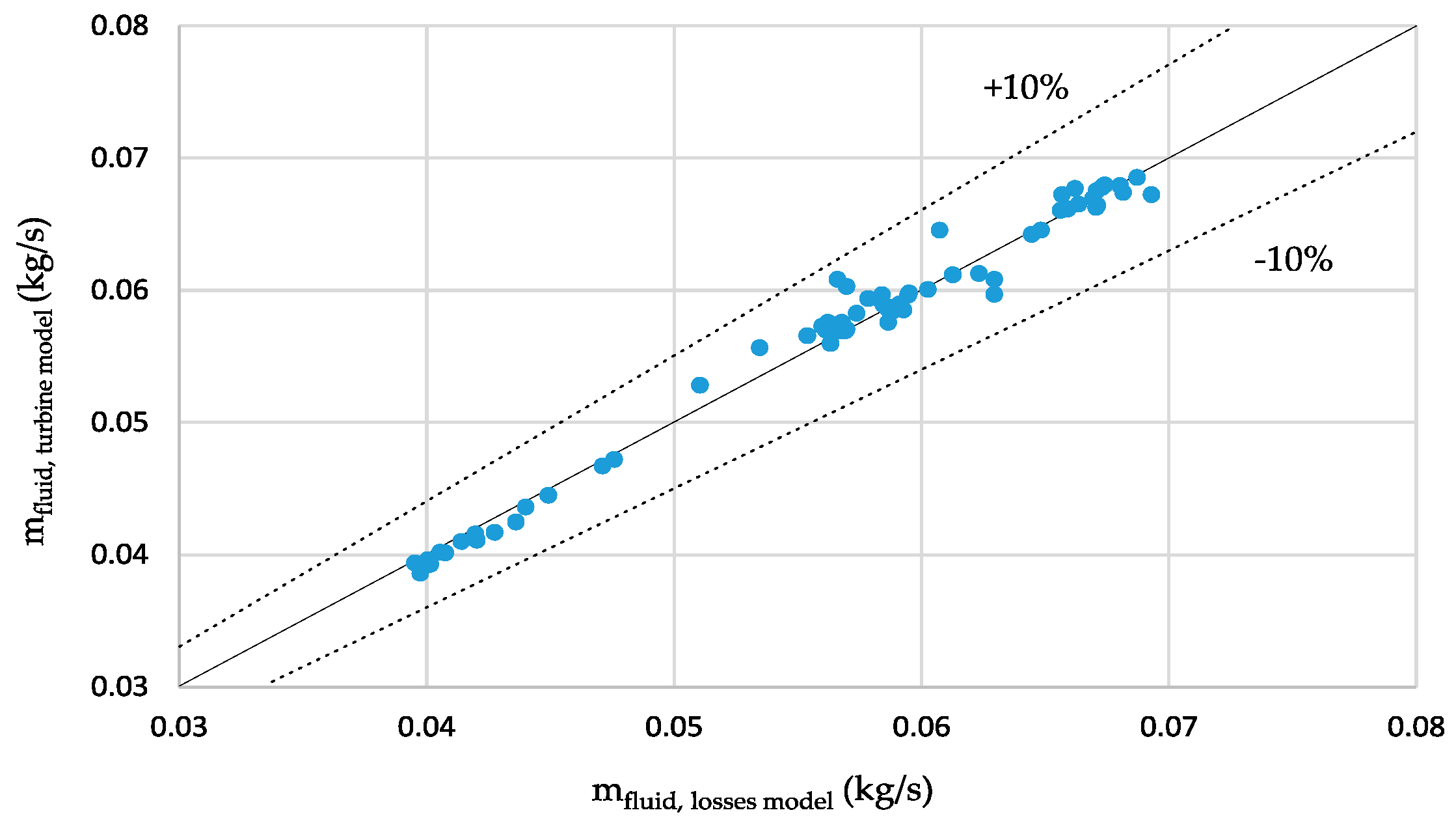
4.3. Mass Flow Rate Validation and Reconciliation

Recent results had led us to calculate an accurate value of the working fluid’s mass flow rate based on the turbine-specific parameter Ᾱ. The mass flow rate reconciliation is shown in Figure 12.
This second calculation, using a deterministic method of the flow rate of the working fluid that ensues from the dimensionless parameter of the turbine Ᾱ, made it possible to verify the confidence interval of the results obtained with the previous calculation method. The relative error between the two methods is less than 7% for all of the tests and less than 5% for 95% of the tests.

5. Conclusions

In this paper, a new ORC installation, for low grade waste heat conversion to produce low power, has been experimentally studied. The interest in this installation results from its high compactness (0.25 m3), the different low-GWP working fluids used, and the performances achieved during the experimental tests. The pure fluid designed for the ORC, NovecTM649, and the zeotropic mixture, composed of NovecTM649 and HFE7000 in respective mass proportions of 80% and 20%, are both environmentally friendly fluids with a null Ozone Depletion Potential and a low Global Warming Potential. These fluids are, therefore, expected to be potential candidates to substitute for fluids traditionally used in ORCs, such as R-134a and R-245fa. Regarding the ORC system, its compactness leads to interesting possibilities to implement this machine in residential and transport areas.
This study presents the results of comparative experimental tests in the mixture and the pure fluid for the investigated ORC and the analysis of these results replaced in the available literature.
With respect to the expansion element, the results obtained in pure NovecTM649 highlight the proper functioning of the specific axial micro-turbine. Regarding those obtained with the zeotropic mixture, the turbine is not mechanically impacted and operates approximately with the same performance as pure fluid. The slight decrease in the component efficiency comes from the lower thermodynamic properties of the HFE7000, the second pure fluid in the mixture. For the same power production range and heat source temperature, in comparison to the classical scroll expander technology, this turbine is very effective.
The overall performances of this installation, at its optimal operating point, classify this ORC using the pure fluid and even more the zeotropic mixture as a high-performance low-power installation, compared to the literature available for low-temperature heat recovery. Hence, these fluids are definitely interesting and may efficiently replace fluids that will soon be banned in current installations. In addition, the use of a zeotropic mixture as a working fluid within an ORC can be a very useful parameter for the system’s adjustment. Indeed, it is possible to improve the overall efficiency of the installation, according to the desired electricity requirements, by optimizing the use of the heat source. The results obtained show that, for power production needs in the range of 0–0.6 kW, the use of the zeotropic mixture fulfills the electrical needs and allows for the heat source’s better utilization, as demonstrated with the corresponding 10% higher thermal efficiency values than the pure fluid values.
Tests are currently underway on the ORC facility to complete the experimental study of this zeotropic mixture for other fluid mass proportions. The agreement in evolution temperatures between the sink source and the condensing glide, and the assumption underlying the highest zeotropic performances, will be deeply screened in future experimental investigations for the corresponding highest operating points.

Author Contributions

Conceptualization, Q.B., N.T., N.C., and N.V.; methodology, Q.B. and N.T.; software, Q.B.; validation, Q.B.; formal analysis, Q.B.; investigation, Q.B.; resources, N.T.; data curation, N.T.; writing—original draft preparation, Q.B.; writing—review and editing, Q.B., N.T., N.C., and N.V.; visualization, Q.B.; supervision, N.T. and N.C.; project administration, N.T.; funding acquisition, N.T. and N.C.

Funding

This research was funded by the French Alternative Energies and Atomic Energy Commission.

Acknowledgments

The authors would like to express their gratitude to the French Alternative Energies and Atomic Energy Commission and the Carnot Energies of the Future Institute.

Conflicts of Interest

The authors declare no conflict of interest.

Nomenclature

Symbols
dimensionless turbine parameter[–]
A*blade critical section[m2]
A0turbine reference section[m2]
c0stagnation turbine soundspeed[m/s]
E ˙ exergy[kW]
hspecific enthalpy[kJ/kg]
m ˙ mass flow[kg/s]
Ppressure[bar]
Q ˙ thermal power[kW]
qvvolumetric flow[L/h]
sspecific entropy[kJ/kg-K]
Ssection de passage[m2]
Ttemperature[°C or K]
W ˙ power[kW]
Greek symbols
ηefficiency [%]
πpressure ratio [–]
γpolytropic coefficient [–]
ρ0 stagnation turbine density [kg/m3]
Subscripts
condcondenser
cfcooling fluid
coolingcooling source
elelectric
evapevaporator
grossgross
heatheating source
hfheating fluid
IIsecond law
ininlet
isisentropic
losseslosses
netnet
outoutlet
prepre-heater
pspumps
refreference
ththermal
turturbine
wfworking fluid
Acronyms
APSAbsolute Pressure Sensor
EFMElectromagnetic Flow Meter
GWPGlobal Warming Potential
HCFCHydrochlorofluorocarbon
HCFOHydrochlorofluoroolefin
HFCHydrofluorocarbon
HFEHydrofluoroether
HFOHydrofluoroolefin
ODPOzone Depletion Potential
ORCOrganic Rankine Cycle
PFDProcess Flow Diagram
PIDProportional Integral Derivative

References

  1. World Overview of the Organic Rankine Cycle Technology. ORC World Map. Available online: http://orc-world-map.org/ (accessed on 18 April 2019).
  2. Quoilin, S.; Broek, M.V.D.; Declaye, S.; Dewallef, P.; Lemort, V. Techno-economic survey of Organic Rankine Cycle (ORC) systems. Renew. Sustain. Energy Rev. 2013, 22, 168–186. [Google Scholar] [CrossRef] [Green Version]
  3. Tauveron, N.; Colasson, S.; Gruss, J.-A. Available systems for the conversion of waste heat to electricity. In Proceedings of the ASME International Mechanical Engineering Congress and Exposition, Montreal, QC, Canada, 14–20 November 2014. [Google Scholar]
  4. Colonna, P.; Casati, E.; Trapp, C.; Mathijssen, T.; Larjola, J.; Turunen-Saaresti, T.; Uusitalo, A. Organic Rankine Cycle Power Systems: From the Concept to Current Technology, Applications, and an Outlook to the Future. J. Eng. Gas Turbines Power 2015, 137, 100801. [Google Scholar] [CrossRef] [Green Version]
  5. Pereira, J.S.; Ribeiro, J.B.; Mendes, R.; Vaz, G.C.; André, J.C. ORC based micro-cogeneration systems for residential application—A state of the art review and current challenges. Renew. Sustain. Energy Rev. 2018, 92, 728–743. [Google Scholar] [CrossRef]
  6. Lion, S.; Michos, C.N.; Vlaskos, I.; Rouaud, C.; Taccani, R. A review of waste heat recovery and Organic Rankine Cycles (ORC) in on-off highway vehicle Heavy Duty Diesel Engine applications. Renew. Sustain. Energy Rev. 2017, 79, 691–708. [Google Scholar] [CrossRef]
  7. Mahmoudi, A.; Fazli, M.; Morad, M.R. A recent review of waste heat recovery by Organic Rankine Cycle. Appl. Therm. Eng. 2018, 143, 660–675. [Google Scholar] [CrossRef]
  8. Braimakis, K.; Preißinger, M.; Brüggemann, D.; Karellas, S.; Panopoulos, K. Low grade waste heat recovery with subcritical and supercritical Organic Rankine Cycle based on natural refrigerants and their binary mixtures. Energy 2015, 88, 80–92. [Google Scholar] [CrossRef]
  9. Papapetrou, M.; Kosmadakis, G.; Cipollina, A.; La Commare, U.; Micale, G. Industrial waste heat: Estimation of the technically available resource in the EU per industrial sector, temperature level and country. Appl. Therm. Eng. 2018, 138, 207–216. [Google Scholar] [CrossRef]
  10. Imran, M.; Haglind, F.; Asim, M.; Zeb Alvi, J. Recent research trends in organic Rankine cycle technology: A bibliometric approach. Renew. Sustain. Energy Rev. 2018, 81, 552–562. [Google Scholar] [CrossRef]
  11. Mansoury, M.; Jafarmadar, S.; Khalilarya, S. Energetic and exergetic assessment of a two-stage Organic Rankine Cycle with reactivity controlled compression ignition engine as a low temperature heat source. Energy Convers. Manag. 2018, 166, 215–232. [Google Scholar] [CrossRef]
  12. Dong, S.; Zhang, Y.; He, Z.; Yu, X.; Zhang, Y.; Kong, X. Optimum design method of Organic Rankine Cycle system based on semi-empirical model and experimental validation. Energy Convers. Manag. 2016, 108, 85–95. [Google Scholar] [CrossRef]
  13. Usman, M.; Imran, M.; Lee, D.H.; Park, B.-S. Experimental investigation of off-grid organic Rankine cycle control system adapting sliding pressure strategy under proportional integral with feed-forward and compensator. Appl. Therm. Eng. 2017, 110, 1153–1163. [Google Scholar] [CrossRef]
  14. Yun, E.; Kim, D.; Yoon, S.E.; Kim, K.C. Experimental study on parallel expander organic rankine cycle with two different capacity expanders. In Proceedings of the ASME International Mechanical Engineering Congress and Exposition 2015, Houston, TX, USA, 13–19 November 2015. [Google Scholar]
  15. Wang, J.; Yan, Z.; Wang, M.; Li, M.; Dai, Y. Multi-objective optimization of an organic Rankine cycle (ORC) for low grade waste heat recovery using evolutionary algorithm. Energy Convers. Manag. 2013, 71, 146–158. [Google Scholar] [CrossRef]
  16. Leontaritis, A.-D.; Pallis, P.; Karellas, S.; Papastergiou, A.; Antoniou, N.; Vourliotis, P.; Kakalis, N.M.; Dimopoulos, G. Experimental Study on a Low Temperature ORC Unit for Onboard Waste Heat Recovery from Marine Diesel Engines. In Proceedings of the ASME International Mechanical Engineering Congress and Exposition 2015, Houston, TX, USA, 13–19 November 2015. [Google Scholar]
  17. Ziviani, D.; James, N.A.; Accorsi, F.A.; Braun, J.E.; Groll, E.A. Experimental and numerical analyses of a 5 kWe oil-free open-drive scroll expander for small-scale organic Rankine cycle (ORC) applications. Appl. Energy 2018, 230, 1140–1156. [Google Scholar] [CrossRef]
  18. Cipollone, R.; Bianchi, G.; Di Battista, D.; Contaldi, G.; Murgia, S. Mechanical Energy Recovery from Low Grade Thermal Energy Sources. Energy Procedia 2014, 45, 121–130. [Google Scholar] [CrossRef] [Green Version]
  19. Chen, H.; Goswami, D.Y.; Stefanakos, E.K. A review of thermodynamic cycles and working fluids for the conversion of low-grade heat. Renew. Sustain. Energy Rev. 2010, 14, 3059–3067. [Google Scholar] [CrossRef]
  20. Cataldo, F.; Mastrullo, R.; Mauro, A.W.; Vanoli, G.P. Fluid selection of Organic Rankine Cycle for low-temperature waste heat recovery based on thermal optimization. Energy 2014, 72, 159–167. [Google Scholar] [CrossRef]
  21. Hærvig, J.; Sørensen, K.; Condra, T.J. Guidelines for optimal selection of working fluid for an organic Rankine cycle in relation to waste heat recovery. Energy 2016, 96, 592–602. [Google Scholar] [CrossRef]
  22. Dickes, R.; Dumont, O.; Guillaume, L.; Quoilin, S.; Lemort, V. Charge-sensitive modelling of organic Rankine cycle power systems for off-design performance simulation. Appl. Energy 2018, 212, 1262–1281. [Google Scholar] [CrossRef]
  23. Landelle, A. Experimental Organic Rankine Cycle Database—v2016.12. Available online: https://github.com/alandelle/Experimental-ORC-database/tree/2016.12.1 (accessed on 18 April 2019).
  24. Muhammad, U.; Imran, M.; Lee, D.H.; Park, B.S. Design and experimental investigation of a 1kW organic Rankine cycle system using R245fa as working fluid for low-grade waste heat recovery from steam. Energy Convers. Manag. 2015, 103, 1089–1100. [Google Scholar] [CrossRef]
  25. Desideri, A.; Gusev, S.; van den Broek, M.; Lemort, V.; Quoilin, S. Experimental comparison of organic fluids for low temperature ORC (organic Rankine cycle) systems for waste heat recovery applications. Energy 2016, 97, 460–469. [Google Scholar] [CrossRef]
  26. Quoilin, S.; Lemort, V.; Lebrun, J. Experimental study and modeling of an Organic Rankine Cycle using scroll expander. Appl. Energy 2010, 87, 1260–1268. [Google Scholar] [CrossRef]
  27. Feng, Y.-Q.; Hung, T.-C.; Wu, S.-L.; Lin, C.-H.; Li, B.-X.; Huang, K.C.; Qin, J. Operation characteristic of a R123-based organic Rankine cycle depending on working fluid mass flow rates and heat source temperatures. Energy Convers. Manag. 2017, 131, 55–68. [Google Scholar] [CrossRef]
  28. Galloni, E.; Fontana, G.; Staccone, S. Design and experimental analysis of a mini ORC (organic Rankine cycle) power plant based on R245fa working fluid. Energy 2015, 90, 768–775. [Google Scholar] [CrossRef]
  29. Chang, J.-C.; Hung, T.-C.; He, Y.-L.; Zhang, W. Experimental study on low-temperature organic Rankine cycle utilizing scroll type expander. Appl. Energy 2015, 155, 150–159. [Google Scholar] [CrossRef]
  30. Miao, Z.; Xu, J.; Yang, X.; Zou, J. Operation and performance of a low temperature organic Rankine cycle. Appl. Therm. Eng. 2015, 75, 1065–1075. [Google Scholar] [CrossRef]
  31. Lei, B.; Wang, W.; Wu, Y.-T.; Ma, C.-F.; Wang, J.-F.; Zhang, L.; Li, C.; Zhao, Y.-K.; Zhi, R.P. Development and experimental study on a single screw expander integrated into an Organic Rankine Cycle. Energy 2016, 116, 43–52. [Google Scholar] [CrossRef]
  32. Saiai, P.; Chaitep, S.; Bundhurat, D.; Watanawanyoo, P. An Experimental Investigation of Vapor Generator Characteristics in a Low-pressure Turbine Engine. Indian J. Sci. Technol. 2014, 7, 1130–1136. [Google Scholar] [CrossRef]
  33. Serrano, D.; Smague, P.; Tona, P.; Leduc, P.; Mintsa, A.C.; Leroux, A.; Chevalier, P. Improving Train Energy Efficiency by Organic Rankine Cycle (ORC) for Recovering Waste Heat from Exhaust Gas. In Proceedings of the ASME International Mechanical Engineering Congress and Exposition 2015, Houston, TX, USA, 13–19 November 2015. [Google Scholar]
  34. Mu, Y.; Zhang, Y.; Deng, N.; Nie, J. Experimental Study of a Low-Temperature Power Generation System in an Organic Rankine Cycle. J. Energy Eng. 2015, 141, 04014017. [Google Scholar] [CrossRef] [Green Version]
  35. Gusev, S.; Ziviani, D.; van den Broek, M. Experimental characterization of single screw expander performance under different testing conditions and working fluids. In Proceedings of the ASME International Mechanical Engineering Congress and Exposition 2015, Houston, TX, USA, 13–19 November 2015. [Google Scholar]
  36. Darawun, W.; Songprakorp, R.; Monyakul, V.; Thepa, S. Testing of Low-grade Heat Source Organic Rankine Cycle with Small Hot Vapor Reciprocating Engine. Energy Procedia 2015, 79, 335–340. [Google Scholar] [CrossRef] [Green Version]
  37. Oudkerk, J.F.; Dickes, R.; Dumont, O.; Lemort, V. Experimental performance of a piston expander in a small- scale organic Rankine cycle. IOP Conf. Ser. Mater. Sci. Eng. 2015, 90, 012066. [Google Scholar] [CrossRef] [Green Version]
  38. Kolasiński, P. The Influence of the Heat Source Temperature on the Multivane Expander Output Power in an Organic Rankine Cycle (ORC) System. Energies 2015, 8, 3351–3369. [Google Scholar] [CrossRef] [Green Version]
  39. Tahir, M.; Yamada, N.; Hoshino, T. Efficiency of compact organic rankine cycle system with Rotary-Vane-Type expander for low-temperature waste heat recovery. Int. J. Environ. Sci. Eng. 2010, 2, 11–16. [Google Scholar]
  40. Wu, Y.-T.; Zhao, Y.-K.; Zhang, C.; Lei, B.; Guo, H.; Ma, C.F. Simulation Study of Cooling System on ORC Performance. Kung Cheng Je Wu Li Hsueh Pao/J. Eng. Thermophys. 2018, 39, 1412–1416. [Google Scholar]
  41. Kosmadakis, G.; Manolakos, D.; Papadakis, G. Experimental investigation of a low-temperature organic Rankine cycle (ORC) engine under variable heat input operating at both subcritical and supercritical conditions. Appl. Therm. Eng. 2016, 92, 1–7. [Google Scholar] [CrossRef]
  42. Montreal Protocol on Substances that Deplete the Ozone Layer. Available online: https://treaties.un.org/doc/publication/unts/volume%201522/volume-1522-i-26369-english.pdf (accessed on 18 April 2019).
  43. Text of the Kyoto Protocol. Available online: https://unfccc.int/process/the-kyoto-protocol/history-of-the-kyoto-protocol/text-of-the-kyoto-protocol (accessed on 18 April 2019).
  44. Bobbo, S.; Nicola, G.D.; Zilio, C.; Brown, J.S.; Fedele, L. Low GWP halocarbon refrigerants: A review of thermophysical properties. Int. J. Refrig. 2018, 90, 181–201. [Google Scholar] [CrossRef]
  45. Wang, H.; Li, H.; Wang, L.; Bu, X. Thermodynamic Analysis of Organic Rankine Cycle with Hydrofluoroethers as Working Fluids. Energy Procedia 2017, 105, 1889–1894. [Google Scholar] [CrossRef]
  46. Sarkar, J. Property-based selection criteria of low GWP working fluids for organic Rankine cycle. J. Braz. Soc. Mech. Sci. Eng. 2016, 39, 1419–1428. [Google Scholar] [CrossRef]
  47. Invernizzi, C.M.; Iora, P.; Preißinger, M.; Manzolini, G. HFOs as substitute for R-134a as working fluids in ORC power plants: A thermodynamic assessment and thermal stability analysis. Appl. Therm. Eng. 2016, 103, 790–797. [Google Scholar] [CrossRef] [Green Version]
  48. Upadhyaya, S.; Gumtapure, V. Thermodynamic analysis of organic Rankine cycle with Hydrofluoroethers as working fluids. IOP Conf. Ser. Mater. Sci. Eng. 2018, 376, 012026. [Google Scholar] [CrossRef]
  49. Navarro-Esbrí, J.; Molés, F.; Peris, B.; Mota-Babiloni, A.; Kontomaris, K. Experimental study of an Organic Rankine Cycle with HFO-1336mzz-Z as a low global warming potential working fluid for micro-scale low temperature applications. Energy 2017, 133, 79–89. [Google Scholar] [CrossRef]
  50. Yang, J.; Ye, Z.; Yu, B.; Ouyang, H.; Chen, J. Simultaneous experimental comparison of low-GWP refrigerants as drop-in replacements to R245fa for Organic Rankine cycle application: R1234ze(Z), R1233zd(E), and R1336mzz(E). Energy 2019, 173, 721–731. [Google Scholar] [CrossRef]
  51. Cambi, M.; Tascioni, R.; Cioccolanti, L.; Bocci, E. Converting a commercial scroll compressor into an expander: Experimental and analytical performance evaluation. Energy Procedia 2017, 129, 363–370. [Google Scholar] [CrossRef]
  52. Qiu, G.; Shao, Y.; Li, J.; Liu, H.; Riffat, S.B. Experimental investigation of a biomass-fired ORC-based micro-CHP for domestic applications. Fuel 2012, 96, 374–382. [Google Scholar] [CrossRef] [Green Version]
  53. Jradi, M.; Li, J.; Liu, H.; Riffat, S. Micro-scale ORC-based combined heat and power system using a novel scroll expander. Int. J. Low-Carbon Technol. 2014, 9, 91–99. [Google Scholar] [CrossRef]
  54. Kaczmarczyk, T.Z.; Zywica, G.; Ihnatowicz, E. Experimental investigation of a radial microturbine in organic rankine cycle system with hfe7100 as working fluid. In Proceedings of the ASME International Mechanical Engineering Congress and Exposition 2015, Houston, TX, USA, 13–19 November 2015. [Google Scholar]
  55. Pu, W.; Yue, C.; Han, D.; He, W.; Liu, X.; Zhang, Q.; Chen, Y. Experimental study on Organic Rankine cycle for low grade thermal energy recovery. Appl. Therm. Eng. 2016, 94, 221–227. [Google Scholar] [CrossRef]
  56. Scaccabarozzi, R.; Tavano, M.; Invernizzi, C.M.; Martelli, E. Comparison of working fluids and cycle optimization for heat recovery ORCs from large internal combustion engines. Energy 2018, 158, 396–416. [Google Scholar] [CrossRef]
  57. Lu, H.; Wang, Z.; Wang, L.; Xu, S.; Hu, B. Experimental study on a small-scale pumpless organic Rankine cycle with R1233zd(E) as working fluid at low temperature heat source. Int. J. Energy Res. 2019, 43, 1203–1216. [Google Scholar] [CrossRef]
  58. Lu, Z.; Wang, R. Experimental and simulation analysis of low temperature heat sources driven adsorption air conditioning, refrigeration, integrating ammonia, and organic expanding power generation. Int. J. Energy Res. 2018, 42, 4157–4169. [Google Scholar] [CrossRef]
  59. Ghaebi, H.; Yari, M.; Gargari, S.G.; Rostamzadeh, H. Thermodynamic modeling and optimization of a combined biogas steam reforming system and organic Rankine cycle for coproduction of power and hydrogen. Renew. Energy 2019, 130, 87–102. [Google Scholar] [CrossRef]
  60. Scaccabarozzi, R.; Tavano, M.; Invernizzi, C.M.; Martelli, E. Thermodynamic Optimization of heat recovery ORCs for heavy duty Internal Combustion Engine: Pure fluids vs. zeotropic mixtures. Energy Procedia 2017, 129, 168–175. [Google Scholar] [CrossRef]
  61. Bonk, C.D.; Laux, C.; Rödder, M.; Neef, M. Design of a 1 KW Organic Rankine Cycle for Teaching and Research Issues. Energy Procedia 2017, 129, 931–938. [Google Scholar] [CrossRef]
  62. Bamorovat Abadi, G.; Kim, K.C. Investigation of organic Rankine cycles with zeotropic mixtures as a working fluid: Advantages and issues. Renew. Sustain. Energy Rev. 2017, 73, 1000–1013. [Google Scholar] [CrossRef]
  63. Modi, A.; Haglind, F. A review of recent research on the use of zeotropic mixtures in power generation systems. Energy Convers. Manag. 2017, 138, 603–626. [Google Scholar] [CrossRef]
  64. Su, W.; Zhao, L.; Deng, S.; Xu, W.; Yu, Z. A limiting efficiency of subcritical Organic Rankine cycle under the constraint of working fluids. Energy 2018, 143, 458–466. [Google Scholar] [CrossRef]
  65. Zhao, L. Zeotropic Mixture and Organic Ranking Cycle. SpringerLink 2017, 133–168. [Google Scholar] [CrossRef]
  66. Xiao, L.; Wu, S.-Y.; Yi, T.-T.; Liu, C.; Li, Y.-R. Multi-objective optimization of evaporation and condensation temperatures for subcritical organic Rankine cycle. Energy 2015, 83, 723–733. [Google Scholar] [CrossRef]
  67. Zhai, H.; An, Q.; Shi, L. Zeotropic mixture active design method for organic Rankine cycle. Appl. Therm. Eng. 2018, 129, 1171–1180. [Google Scholar] [CrossRef]
  68. Zhao, L.; Bao, J. Thermodynamic analysis of organic Rankine cycle using zeotropic mixtures. Appl. Energy 2014, 130, 748–756. [Google Scholar] [CrossRef]
  69. Deethayat, T.; Asanakham, A.; Kiatsiriroat, T. Performance analysis of low temperature organic Rankine cycle with zeotropic refrigerant by Figure of Merit (FOM). Energy 2016, 96, 96–102. [Google Scholar] [CrossRef]
  70. Kuo, C.-R.; Hsu, S.-W.; Chang, K.-H.; Wang, C.-C. Analysis of a 50kW organic Rankine cycle system. Energy 2011, 36, 5877–5885. [Google Scholar] [CrossRef]
  71. Zhou, Y.; Zhang, F.; Yu, L. The discussion of composition shift in organic Rankine cycle using zeotropic mixtures. Energy Convers. Manag. 2017, 140, 324–333. [Google Scholar] [CrossRef]
  72. Tian, H.; Li, L.; Shu, G.; Yan, N.; Li, X.; Yu, Z. Composition shift in zeotropic mixture–based organic Rankine cycle system for harvesting engine waste heat. Int. J. Energy Res. 2018, 42, 4345–4359. [Google Scholar] [CrossRef]
  73. Chys, M.; van den Broek, M.; Vanslambrouck, B.; De Paepe, M. Potential of zeotropic mixtures as working fluids in organic Rankine cycles. Energy 2012, 44, 623–632. [Google Scholar] [CrossRef]
  74. Landelle, A.; Tauveron, N.; Revellin, R.; Haberschill, P.; Colasson, S.; Roussel, V. Performance investigation of reciprocating pump running with organic fluid for organic Rankine cycle. Appl. Therm. Eng. 2017, 113, 962–969. [Google Scholar] [CrossRef]
  75. 3MTMNovecTM649 Engineered Fluid. Available online: https://multimedia.3m.com/mws/media/569865O/3mtm-novectm-649-engineered-fluid.pdf (accessed on 18 April 2019).
  76. 3MTM NovecTM 7000 Engineered Fluid. Available online: https://multimedia.3m.com/mws/media/121372O/3m-novec-7000-engineered-fluid-tds.pdf (accessed on 18 April 2019).
  77. EES: Engineering Equation Solver|F-Chart Software: Engineering Software. Available online: http://www.fchart.com/ees/ (accessed on 18 April 2019).
  78. REFPROP. NIST. 18 April 2013. Available online: https://www.nist.gov/srd/refprop (accessed on 18 April 2019).
  79. McLinden, M.O.; Perkins, R.A.; Lemmon, E.W.; Fortin, T.J. Thermodynamic Properties of 1,1,1,2,2,4,5,5,5-Nonafluoro-4-(trifluoromethyl)-3-pentanone: Vapor Pressure, (p, ρ, T) Behavior, and Speed of Sound Measurements, and an Equation of State. J. Chem. Eng. Data 2015, 60, 3646–3659. [Google Scholar] [CrossRef]
  80. Outcalt, S.L.; Lemmon, E.W. Bubble-point measurements of eight binary mixtures for organic Rankine cycle applications. J. Chem. Eng. Data 2013, 58, 1853–1860. [Google Scholar] [CrossRef]
  81. Nederstigt, P. Real Gas Thermodynamics: And the Isentropic Behavior of Substances; Delft University of Technology: Delft, The Netherlands, 2017; pp. 1–112. Available online: http://resolver.tudelft.nl/uuid:ee16f7e5-4251-4629-9192-8f4a2e3d599b (accessed on 17 April 2019).
  82. Landelle, A.; Tauveron, N.; Haberschill, P.; Revellin, R.; Colasson, S. Organic Rankine cycle design and performance comparison based on experimental database. Appl. Energy 2017, 204, 1172–1187. [Google Scholar] [CrossRef]
Figure 1. The Experimental Organic Rankine Cycle (a) Process Flow Diagram (PFD); (b) Picture; (c) Diagram.
Applsci 09 01865 g001
Figure 2. The polytropic coefficient in accordance with (a) Pure fluid; (b) Mixture.
Applsci 09 01865 g002
Figure 3. The turbine’s dimensionless parameter according to the pressure ratio.
Applsci 09 01865 g003
Figure 4. The turbine’s overall electrical efficiency according to the pressure ratio.
Applsci 09 01865 g004
Figure 5. The expander electrical efficiency map for the Organic Rankine Cycle (ORC) up to 10 kW.
Applsci 09 01865 g005
Figure 6. The ORC performance according to electrical production in the pure fluid and the mixture. (a) Thermal efficiency; (b) Second law efficiency.
Applsci 09 01865 g006
Figure 7. The ORC performance according to electrical production in the pure fluid and the mixture (isoparameters).
Applsci 09 01865 g007
Figure 8. The T-s plot of the ORC cycle corresponding to the highest experimental point regarding electrical production: (a) NovecTM649; (b) 0.8NovecTM649/0.2HFE7000.
Applsci 09 01865 g008
Figure 9. The ORCs’ distribution according to their gross thermal efficiency.
Applsci 09 01865 g009
Figure 10. The ORCs’ distribution according to their gross second law efficiency.
Applsci 09 01865 g010
Figure 11. ORC performances according to the electrical production in the pure fluid and the mixture.
Applsci 09 01865 g011
Figure 12. The working fluid’s mass flow rate reconciliation between the losses model and the turbine model.
Applsci 09 01865 g012
Table 1. The main properties of the considered fluids.
PropertyNovecTM6490.8NovecTM649/0.2HFE7000HFE7000
TypeDryDryDry
Molar mass (g/mol)316283.2200.1
Normal boiling point (°C)49.141.234.2
Normal latent heat (kJ/kg)88.199.6133.9
Critical temperature (°C)168.7165.6164.6
Critical pressure (bar)18.720.324.8
Ozone Depletion Potential000
Global Warming Potential1107530
InflammabilityNonflammableNonflammableNonflammable
Table 2. Measurement devices’ characteristics.
VariableDeviceRangeUncertainty
Electrical power Wattmeter0–3250 W±0.3%
Volumetric flow rate (heat source)EFM0–3500 L/h±0.23%
Volumetric flow rate (cooling source)EFM0–2500 L/h±0.33%
TemperatureType-K thermocouples0–1100 °C±0.1 °C
PressureAPS0–7 bar±1%
Table 3. Main parameter settings.
Tin,hf,evapTin,cf,condqv,hfqv,cfwf
(°C)(°C)(L/h)(L/h)(kg/s)
11013.5300–3500250–25000.055–0.069
Table 4. The calculated data for the optimized highest points.
Data NovecTM6490.8NovecTM649/0.2HFE7000
m ˙ h f (kg/s)0.40.4
m ˙ c f (kg/s)0.2360.56
m ˙ w f (kg/s)0.0650.057
T i n , h f , e v a p (°C)110110.2
T i n , c f , c o n d (°C)13.512.6
T r e f (°C)13.512.6
P i n , w f , t u r (bar)4.54.2
P o u t , w f , t u r (bar)0.530.45
Q ˙ h e a t (kW)1210.8
Q ˙ c o o l i n g (kW)109.3
W ˙ e l , t u r (kW)0.7150.703
W ˙ e l , p s (kW)0.1040.104
η t u r (%)58.256
η i s , t u r (%)61.461.5
η t h , n e t (%)55.6
η I I , n e t (%)20.822.4

