Operation Characteristics and Transient Simulation of an ICE-ORC Combined System
by
 ,
,
Tong Liu
1, 
Enhua Wang
1,*,
Fanxiao Meng
1,
Fujun Zhang
1,
Changlu Zhao
1,
Hongguang Zhang
2 and
Rui Zhao
2 1
School of Mechanical Engineering, Beijing Institute of Technology, Beijing 100081, China
2
College of Environmental and Energy Engineering, Beijing University of Technology, Beijing 100124, China
*
Author to whom correspondence should be addressed.
Appl. Sci. 2019, 9(8), 1639; https://doi.org/10.3390/app9081639
Submission received: 2 April 2019
/
Revised: 14 April 2019
/
Accepted: 16 April 2019
/
Published: 19 April 2019
(This article belongs to the Special Issue Organic Rankine Cycle Systems for Waste-Heat Recovery)
Abstract
:Featured Application
A control strategy for an ORC is designed and a transient simulation is performed together with an ICE. The method can be used to develop the coordination control of ICE-ORC combined system.
Abstract
Currently, internal combustion engines (ICEs) are still the main power for transportation. Energy conservation and emission reduction for ICEs have become the driving force of the industrial R&D in recent years. Organic Rankine cycle (ORC) is a feasible technology to recover the waste heat of an ICE so that the energy efficiency can be enhanced apparently. However, there are still many obstacles needed to be overcome for the application of an ORC together with an ICE. When a vehicle is driving, the operation conditions of the ICE vary in a large range. The operation of the ORC needs to be regulated accordingly to achieve maximum efficiency. In this study, the operation characteristics of an ICE-ORC combined system is investigated and the transient performance is analyzed. First, an integrated simulation model of the ICE and the ORC was built in GT-POWER software. A 5 kW single-screw expander was employed for the ORC system. The working characteristics of the ORC system were evaluated under various working conditions of the ICE. The matching principles of the ORC with the ICE were discussed and the optimal operation conditions of the ORC over the entire engine’s working range were obtained. Subsequently, a feedforward control strategy for the ORC system was designed in MATLAB/SIMULINK. Finally, the entire model was simulated under a transient driving cycle of a vehicle. The results indicate that the pump speed and the expander speed are two important parameters and must be adjusted according to the engine’s working condition. The speed of the single-screw expander maintains in the low-speed region and the pump speed is tuned to achieve a high evaporation pressure and a proper superheat degree of the working fluid at the inlet of the expander. Thus, the net power output can be maximized. The designed feedforward control strategy can adjust the working condition of the ORC automatically to match with the working condition of the ICE. The ORC operates intermittently and an impulse power is output under the urban driving conditions. However, the working time of the ORC is increased significantly and the power output is relatively higher under the highway conditions.
1. Introduction
Currently, internal combustion engines (ICEs) are still the main power for transportation. Energy conservation and emission reduction are two critical tasks for the ICE industry all over the world. Organic Rankine cycle (ORC) is a feasible technology to recover the waste heat of an ICE so that the energy efficiency can be enhanced apparently. Compared with other technologies such as improvements of the combustion and friction, the utilization of waste heat has a greater potential for energy conservation and emission reduction. ORC technology is a method that can generate power from a low-temperature heat source such as the waste heat of the exhaust and the coolant of an ICE. For exhaust heat recovery, the working fluid of the ORC absorbs heat from the exhaust and outputs power via an expander. Hence, the total power output and the energy efficiency of the ICE-ORC system are increased [1]. The emissions of the ICE also decrease due to a reduction of the fuel consumption [2]. There are various waste heat recovery technologies such as the thermoelectric generator, steam Rankine cycle, and Kalina cycle. However, ORC technology has a high thermal efficiency and good security, which has drawn extensive attentions in recent years [3].
There are many parameters that will influence the performance of an ORC [4,5]. The selection of the organic working fluid is very important [6,7]. Shu et al. selected an alkane as the working fluid and compared the performance indicators including the thermal efficiency, the work output, and the expander size parameters. The results showed that the performances of cycloalkanes such as cyclohexane were relatively superior. However, the condensing pressure of the alkanes was low. Thus, it was difficult to realize subcooling in an actual working system [8]. Zhu et al. compared the performances of an ORC using R113, R123, R245fa, ethanol, and water. It was concluded that ethanol and R113 had better performances. However, R113 and R123 belonged to CFCs (chlorofluorocarbon), which violated the requirements for green energy and environmental protection. Ethanol and R245fa were more suitable [9]. Dai et al. analyzed the optimal performances of different working fluids for various power cycles using the same waste heat. The results indicated that the ORC was superior to the steam cycle and the converting efficiency from low-grade waste heat to useful energy was higher [10]. Wang et al. analyzed the performances of different working fluids in specific operation regions by using the thermodynamic model built by MATLAB and REFPROP. The results showed that the thermodynamic performances of R11, R141b, R113, and R123 were slightly higher than those of the others. However, R245fa and R245ca were environmentally-friendly fluids and more suitable for the waste heat recovery of engines [11]. Zhang et al. compared the economic performances of an ORC using R123 and R245fa as working fluids and the influences of the operation parameters were evaluated [12].
Although there are many investigations devoted to the ORC system for waste heat recovery of ICE, this technology still faces huge difficulty for practical application. Peris et al. analyzed six different architectures of ORC using ten non-flammable working fluids for waste heat recovery of jacket cooling water and the double regenerative ORC using SES36 achieved the maximum net efficiency of 7.15 [13]. Seyedkavoosi et al. designed a two-parallel-step ORC configuration to recover waste heat from the engine coolant and the exhaust gas simultaneously [14]. Wang et al. proposed a dual-loop ORC system to recover the exhaust and coolant waste heat that could improve the fuel efficiency evidently [15]. Tian et al. evaluated the performance of different ORCs with various working fluids [16]. Sprouse and Depcik [17] and Shi et al. [18] summarized the recent investigations on engine waste heat recovery and Karvonen et al. [19] reviewed the relevant patents. Zhao et al. developed a simulation model for a diesel engine with an ORC system in GT-POWER. The steady simulation results indicated that the power output was increased by 4.13 kW and the fuel consumption was reduced by 3.61 g/kWh [20]. Zhang et al. built an ICE-ORC integrated model and a particle swarm optimization method was used to optimize the ORC system [21]. Vincent et al. evaluated the transient performance of a Rankine cycle system for waste heat recovery of a heavy-duty truck and compared it to the steady-state results [22].
The operation parameters of an ORC system have a great influence on the performance. Therefore, a proper configuration of these parameters is important for the performance improvement and cost reduction. Park et al. designed a speed estimation algorithm for a turbine-generator that utilized a digital phase-locked loop and a state observer to detect the positive-sequence voltages [23]. Some investigations were committed to the parameter optimization of the key components for an ORC system [24]. Roy et al. carried out an optimization of the turbine inlet pressure to maximize the output work and the efficiency of the system along the saturated vapor line and the isobaric superheating under different pressures [25]. Yu et al. evaluated the influence of the evaporating pressure and the engine operation conditions on the system performance [26]. Wang et al. used a NSGA-II algorithm to optimize the exergy efficiency and the overall capital cost using the turbine inlet pressure, the turbine inlet temperature, the pinch temperature difference, the approach temperature difference, and the condenser temperature difference as the decision variables [27]. Yang et al. studied the influences of six working parameters on the thermo-economic performance of a double-loop ORC system. The results indicated that the thermal efficiency of the double-loop ORC system was in the range of 8.97–10.19% across the whole operating range of the engine [28]. Boyaghchi and Sohbatloo used the NSGA-II optimization algorithm and three objective functions with regard to the thermodynamic, economic, and environmental impact performances were selected to optimize the ORC system [29]. Zhang et al. conducted a performance comparison and a parameter optimization for a subcritical ORC and a transcritical power cycle for low-temperature geothermal power generation based on the levelized cost. Although the thermal efficiency and the exergy efficiency of the transcritical cycle with R125 were less than those of the ORC with R123 by 46.4% and 20%, respectively, the overall recovery rate of the transcritical cycle was 20.7% higher than that of the subcritical cycle [30]. The influences of the evaporation and condensation temperatures and the superheat degree of the high-temperature loop on the performance of a dual-loop ORC system for engine waste heat recovery were studied by Ge et al. [31].
When a vehicle is driving, the operation conditions of the ICE vary in a large range. For the ORC operating together with an ICE, the control strategy and the transient performance of the ORC system are very important. Lee et al. studied the transient response of a 50 kW ORC system when the mass flow rate of the cooling medium varied in the condenser [32]. Xie et al. established a Rankine cycle model and discussed the operating performance under an actual driving cycle. The results indicated that the road efficiency of the Rankine cycle was as low as 3.63%, less than half of the rated power point whose efficiency was 7.77% [33]. Jin et al. built a dynamic response model with regard to the mass flow in the condenser under transient working conditions and four different control strategies were compared [34]. Li et al. designed a CO2 transcritical power cycle and the results indicated that the pump speed, the exhaust temperature, and the cooling water temperature had great impacts on the net power output and the thermal efficiency of the system [35]. Shu et al. compared 14 different working fluids and found that they had different dynamic characteristics [36]. Andwari et al. designed an ORC for exhaust heat recovery of a hybrid powertrain and three different driving cycles (FTP-75, EUDC, and US06) were used to evaluate the extent of fuel reduction [37].
The operation characteristics of the expander has a great influence on the performance of an ORC system [38]. Li et al. designed a predicted method for the efficiency of a radial-inflow turbine and compared with a constant turbine efficiency method. The results indicated the system performances of these two different methods were different evidently [39]. Although several investigations were performed with regard to the dynamic performance of an ORC operating together with an ICE, most of them employed a scroll expander or a turbine. The single-screw expander is a positive displacement expander, which has a compact volume and a good force balance, leading to low noise and a small vibration during the working process. In this study, the dynamic performance of an ORC using a single-screw expander for exhaust heat recovery is optimized based on the working conditions of the ICE and the transient operation characteristics of the ICE-ORC combined system is investigated. First, a combined simulation model consisting of the ICE and the ORC with a single-screw expander is set up in GT-POWER and the operation characteristics of the ORC system under the rated power condition of the ICE is studied. The optimal operation conditions of the ORC system are obtained according to the working conditions of the ICE. Then, a control strategy of the ORC system based on a feedforward method is designed in MATLAB. The dynamic operation performance of the ICE-ORC system is simulated under a transient driving cycle. The results indicate that the designed control strategy can operate properly and the efficiency of the entire system can be increased under some driving conditions. The transient performance under the highway conditions is better than that of the urban driving conditions. The results can provide a reference for the practical application of ORC system for waste heat recovery of ICE on vehicles.
2. Simulation Model of ICE-ORC System
2.1. ICE Modeling
A four-cylinder turbocharged diesel engine was selected for this study. The engine type was BJ493ZLQ3, which was manufactured by Beijing Foton Co., Ltd. (Beijing, China). The main technical parameters are listed in Table 1.
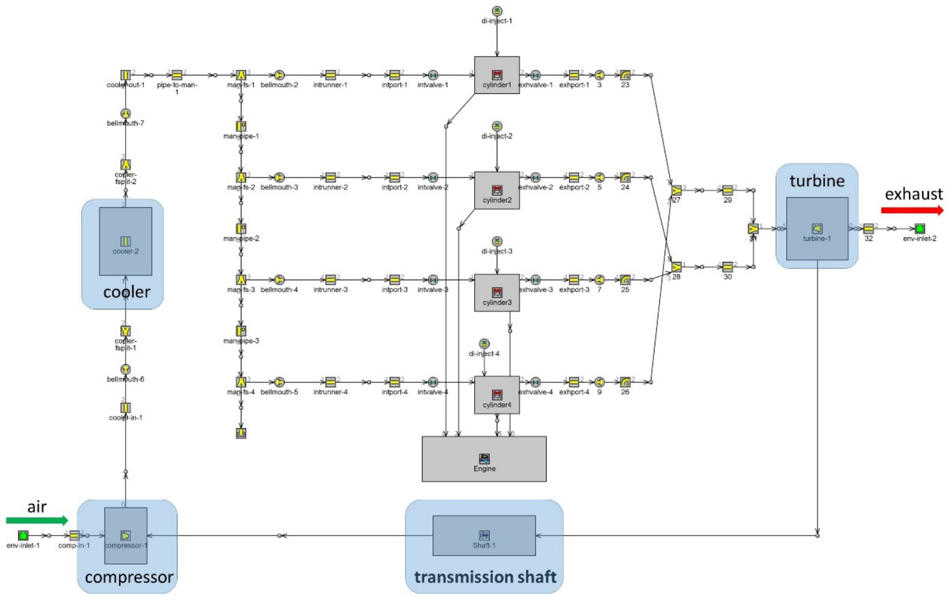
The engine was modeled by a zero-dimensional model in the software GT-POWER. Normally, three-dimensional simulation can give the detailed turbulent flow and combustion process inside the cylinder [40]. However, it will take a long time to run the simulation. In this study, only the transient variations of the temperature and the mass flow rate of the exhaust gas were considered and zero-dimensional simulation was enough. Therefore, GT-POWER was used to model the diesel engine. Figure 1 shows the engine model in GT-POWER, mainly consisting of the intake system, the four cylinders, the crankshaft, the exhaust system, and the turbocharger. The complicated working processes inside the cylinder could be represented as a function of the mass of the working fluid, the in-cylinder pressure and temperature. In this model, the Weibo function was used to determine the heat release rate and the working processes for the four strokes were expressed by ordinary differential equations with regard to the crank rotation angle. Some assumptions were assumed and listed as follows:
- (1)
- The thermodynamic properties of the working fluid such as the internal energy and the specific heat capacity are functions of the temperature and the components.
- (2)
- The fluctuations of the pressure and temperature inside the intake system are neglected.
- (3)
- The thermodynamic state inside the cylinder is considered homogeneous and the influence of the residual combusted gas inside the cylinder is ignored.
The compressor and the turbine should operate in the regions with high efficiencies to ensure a good match of the turbocharger with the engine. The operation trajectories of the compressor and the turbine are shown in Figure 2 under the full-load conditions. Most of the operation points are in the high-efficiency regions.
The simulated data were validated by the measured data under the full-load conditions. The detailed descriptions can be found in Liu et al. [41]. At the rated power point, the simulated engine power was slightly greater than the measured one. The differences between the simulated results and the measured results for the engine power, the torque, and the fuel consumption were less than 7.8%, indicating that the accuracy of the built engine model could fulfil the requirement. The simulated engine power increased as the engine speed rose under the full-load conditions. The engine torque first increased and then decreased while the fuel consumption rate showed an opposite trend.
2.2. ORC Modeling
An ORC with a simple architecture was used in this study shown as Figure 3. The system was mainly composed of a pump, an evaporator, an expander, a condenser, a reservoir, and the connecting pipes. R245fa was selected as the working fluid and its thermodynamic properties were obtained by the database of Refprop, which was embedded in the GT-POWER.
2.2.1. Evaporator
The waste heat of the exhaust gas was transferred to the working fluid inside the evaporator. A shell-and-tube heat exchanger was employed in this study. The main parameters are listed in Table 2. The heat transfer process inside the evaporator can be divided into three zones: The liquid zone, the two-phase zone, and the gaseous zone. For the single-phase zone, the convective heat transfer of the working fluid was determined by the Dittus-Boelter equation:
where h is the convective heat transfer coefficient (), Re is the Reynolds number, Pr is the Prandtl number, K is the thermal conductivity (), and D is the characteristic length.
For the two-phase zone, Shah-Thome equation was used to calculate the convective heat transfer coefficient:
where x is the quality of the two-phase working fluid, P is the operation pressure, and Pcr is the critical pressure.
2.2.2. Condenser
The low-pressure gaseous working fluid was transformed into a liquid state inside the condenser. A plate condenser was employed in this study and the main parameters are listed in Table 3.
The model of the condenser was similar with the evaporator. For the single-phase zone, Dittus-Boelter equation was used. For the two-phase zone, Yan-Lin equation was used to determine the convective heat transfer coefficient:
where ρl is the saturated liquid density, ρg is the saturated gaseous density, q is the heat flow density, hv is the enthalpy of the saturated gas, and hf is the enthalpy of the working fluid.
2.2.3. Expander and Pump
The single-screw expander in Zhang et al. [42] was employed for the ORC in this study. The maximum evaporation pressure was set to 1.4 MPa. The expander model in GT-POWER was set up by inputting the measured performance data of the single-screw expander including the expander speed, the mass flow rate, the efficiency, and the temperatures and the pressures at the inlet and outlet of the expander.
There are mainly two kinds of pumps for the ORC system: The centrifugal pump and the positive displacement pump. The volume flow rate of the positive displacement pump is proportional to the pump speed. The efficiency of the pump can be in a high level under all the speeds. Therefore, a positive displacement pump was employed in this study. When the engine operates at the rated power point, the maximum mass flow rate of the working fluid was approximately 300 g/s with an evaporation pressure of 1.4 MPa. Therefore, the operation range of the pump was set as 70–350 g/s with a speed range of 1300–2500 r/min. The corresponding efficiency was between 30% and 80%. Finally, a reservoir with a volume of 4 L was inserted and all the components were connected in series.
2.3. ICE-ORC Combined System
To evaluate the operation characteristics of the ICE-ORC combined system, the ICE model and the ORC model were integrated in the GT-POWER, shown as Figure 4. The exhaust gas from the ICE model was transmitted to the ORC model as the heat source. The module “FlowCircuitSplitter” was inserted to the flow path of the exhaust gas. In the module, the temperature and pressure of the exhaust gas were input to the ORC model directly while the mass flow rate of the exhaust gas was determined by a proportional–integral–derivative (PID) block. The parameters of the PID block were adjusted to ensure a good consistency of the mass flow rate between the ICE and the ORC models.
3. Operating Characteristics of the ICE-ORC System
3.1. Performance Under the Rated Power Condition
The performance of the ORC system when the engine operates under the rate power condition was investigated. The influences of the working parameters of the ORC system were evaluated and the optimal parameters were obtained. The results for the engine performance under the rated power are given in Table 4.
Based on the established ICE-ORC model, the simulated performances of the ORC system as a function of the pump speed and the expander speed when the ICE operates under the rated power condition are shown in Figure 5. The results for the net power output are shown in Figure 5a, which increased significantly as the expander speed decreased. The influence of the pump speed was relatively small. When the expander speed was high, the net power reduced as the pump speed rose. When the expander speed was low, an opposite tendency was observed. From the measured performance characteristics of the single-screw expander in Zhang et al. [42], the efficiency of the expander increased as the mass flow rate rose under a low expander speed. However, the efficiency of the expander decreased with the mass flow rate when the expander speed was high. Therefore, the net power output showed a similar trend.
The maximum net power reached 3.08 kW with an expander speed of 1350 r/min and a pump speed of 2350 r/min. The evaporation pressure will increase as the expander speed reduces, which is beneficial for the improvement of the net power output. However, if the expander speed is too small, the efficiency of the expander will decrease, resulting in a low net power output again. The efficiency of the expander reaches a high level with an expander speed in the range of 1300–1500 r/min [42]. Therefore, a maximum net power output is achieved with an expander speed slightly higher than 900 r/min. The results for the thermal efficiency of the ORC are shown in Figure 5b. The surface of the thermal efficiency exhibited a similar tendency with that of the net power output because the heat transfer quantities inside the evaporator were very close for different operation conditions defined by the pump speed and the expander speed. For the designed ORC system, the maximum thermal efficiency reached 4.5% accordingly.
The influences of the working parameters on the system performance were analyzed further and the results are shown in Figure 6. The net power as a function of the evaporation pressure and the mass flow rate of R245fa is displayed in Figure 6a. The net power increases apparently as the evaporation pressure increases because the enthalpy difference between the inlet and outlet of the expander is increased. The pump speed and the expander speed are two important working parameters that will influence the evaporation pressure. In this study, the pump speed was used to control the mass flow rate and the expander speed was used to control the evaporation pressure. When the pump speed keeps constant, the evaporation pressure will increase as the expander speed decreases. Therefore, a maximum net power was achieved under a low expander speed as shown in Figure 5a. Results for the outlet temperature of the evaporator are shown in Figure 6b. The corresponding outcomes for the superheat degree of the working fluid at the outlet of the evaporator are shown in Figure 6c. The outlet temperature decreased evidently as the mass flow rate increased. If the mass flow rate was small, the specific enthalpy difference between the inlet and outlet of the evaporator enlarged, leading to a high outlet temperature. The superheat degree would increase accordingly. Meanwhile, the waste heat of the exhaust gas could not be utilized fully. On the other hand, the evaporation pressure shows a negative correlation with the outlet temperature for a fixed mass flow rate. The evaporation pressure must be enhanced to a high level until the superheat degree decreases to a value slightly higher than 0 because the influence of the evaporation pressure was more significant than the outlet temperature of the evaporator on the improvement of the net power output.
When the engine operated under the rated power point, the evaluated optimal mass flow rate was approximately 300 g/s. In Figure 6a, a high value for the net power output was obtained with a mass flow rate in the range of 280–320 g/s. If the mass flow rate was too small, the evaporation pressure would decrease. If the mass flow rate was too large, the superheat degree would drop, which had a negative influence on the net power.
3.2. Influence of the Expander Efficiency
In the previous analysis, the measured data for the expander efficiency in Zhang et al. [42] were used. The maximum expander efficiency was only 45%. If the mechanical design and manufacturing of the single-screw expander were improved, a maximum efficiency of 60% could be realized, close to what a positive displacement expander normally could achieve [43]. According to the measured data in [42], the expander efficiency can be plotted as a surface with regard to the mass flow rate and the pressure ratio. In this section, this surface for the expander efficiency was assumed to be improved by a geometric translation so that the maximum expander efficiency equals 60%. Then, the influence of the expander efficiency on the ORC system was investigated.
Figure 7 shows a comparison of the net power and the thermal efficiency between the original and improved data of the expander efficiency. If the expander efficiency was improved, the variation tendencies for the net power output and the thermal efficiency were similar with those using the original low expander efficiency. However, the net power was increased by 0.6–0.7 kW for each operation point (19.68–53.66% compared with the original data). Accordingly, the thermal efficiency was improved by 25.53–51.6%. The improvement was more significant in the region with a low net power output. Therefore, keeping the expander efficiency in a high level could improve the system performance apparently. The following analysis will employ the improved data of the expander efficiency to evaluate the energy efficiency of the ICE-ORC combined system.
3.3. Operation Characteristics Under Various Conditions
The high temperature exhaust gas was delivered to the ORC as the heat source. The temperature and mass flow rate of the exhaust gas varied with the engine speed and the engine load. Therefore, the operation characteristics of the ICE had a great influence on the performance of the ORC. Normally, a vehicular ICE would operate under various conditions such as high-speed or high-load conditions during a journey. It is necessary to investigate the performance of the ORC when the ICE operates over a wide range.
First, the waste energy of the exhaust gas over the entire engine’s operation range was analyzed. The mass flow rate of the exhaust gas increased as the engine speed rose. The simulated mass flow rate ranged from 35.94 g/s to 185.59 g/s. The exhaust temperature increased as the engine load rose. When the engine speed was fixed, the engine load was essentially proportional to the injected fuel amount. A higher engine load resulted in a higher exhaust temperature because the compression ratio of the engine was constant, leading to a larger amount of waste energy. The simulated exhaust temperature was in the range of 599–972 K. In this study, the minimum exhaust temperature at the outlet of the evaporator was fixed as 350 K. Accordingly, the maximum waste energy for each operation point of the engine was determined according to the mass flow rate of the exhaust and the temperature decrease through the evaporator. The obtained exhaust energy was approximately proportional to the power output of the engine, increasing as the engine speed or the engine load increased. The maximum exhaust energy reached 75.55 kW under the rated power condition of the engine.
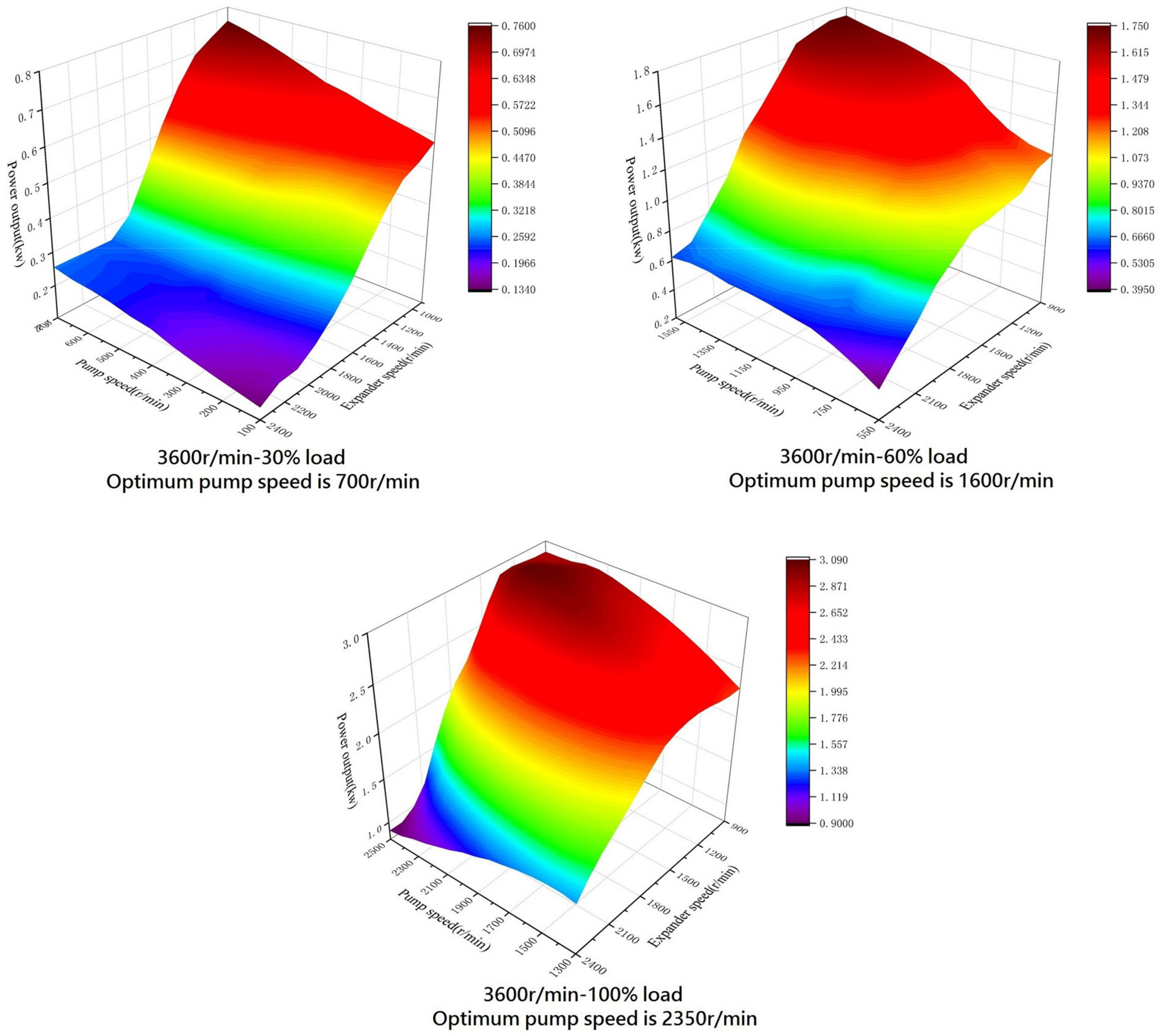
Different engine operation points based on the engine speed and the engine torque were selected over the entire engine’s operation range. The ICE-ORC model was simulated under each operation point and the results were analyzed. Figure 8 shows the results for the performance of the ORC under a constant engine load while the engine speed increased gradually. The engine load was fixed at 100% while the engine speed was set to 1600, 2600, and 3600 r/min, respectively. The variation tendencies of the net power as a function of the pump speed and the expander speed under different engine speeds were similar. However, the optimal operation point of the ORC with a maximum net power output varied with the engine speed. The optimal pump speed increased apparently as the engine speed rose. The results for the net power of the ORC under different engine loads with an engine speed of 3600 r/min are shown in Figure 9. The optimal pump speed increased as the engine load rose. Because the exhaust energy increased as the engine load increased, the mass flow rate must be increased accordingly to utilize the waste energy comprehensively, resulting in an increase of the optimal pump speed.
The optimal operation point of the ORC under various operation conditions of the engine were determined by the ICE-ORC model and the results are shown in Figure 10. Figure 10a shows the results for the optimal pump speed. The optimal pump speed reached a peak of 2350 r/min. Meanwhile, the engine operated at the rated power point. The optimal pump speed decreased as the engine power dropped. When the exhaust energy declined to 16–17 kW, the pump speed reduced to a minimum to keep the superheat degree of the working fluid at the outlet of the evaporation greater than 0. In the lower-left region of Figure 10a, the exhaust energy was too small to drive the ORC system. Hence, there existed a boundary line, below which the ORC system must stop.
The results for the optimal expander speed are shown in Figure 10b. The performance data of the single-screw expander was measured with an expander speed greater than 900 r/min. The optimal expander speed approximated to the minimum in most of the regions. Only when the engine power was close to the rated power point, the expander speed increased apparently. In practice, when the engine operation condition changes, the working speeds of the pump and the expander must be controlled based on the optimal results shown in Figure 10 so that a maximum net power of the ORC is achieved.
4. Transient Simulation of the ICE-ORC System
The performances of the ORC under various operation conditions of the engine were analyzed and the optimal operation conditions of the ORC with regard to the engine speed and the engine torque were obtained. When a vehicle is running on the road, most of the operation conditions of the engine are transient. Therefore, it is important to investigate the operation characteristics of the ORC system when the engine operates under practical transient conditions.
The pump speed and the expander speed were controlled during the transient working process to get a high net power output. Based on the results of Figure 10, a feedforward control method was used to determine these two speeds according to the engine speed and the engine torque. The model for the ICE-ORC combined system and the control strategy were integrated in GT-POWER together with MATLAB as shown in Figure 4. The ICE-ORC model was built in GT-POWER and the control strategy was designed in MATLAB/Simulink. The interface block “SimulinkHarness” was used to connect the signals between these two different programs.
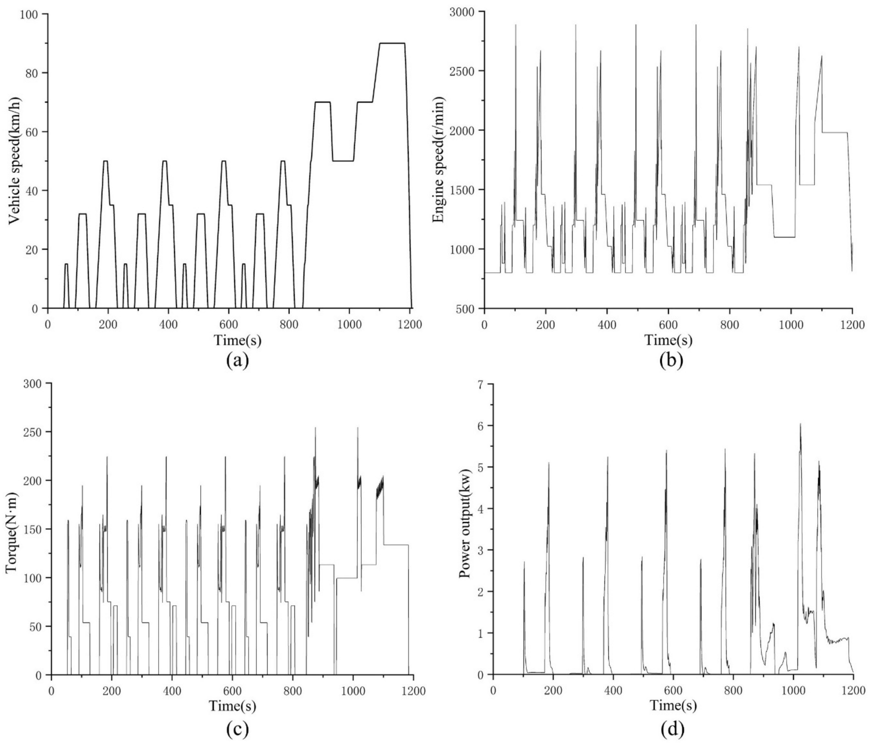
In this study, the ECE-EUDC driving cycle was selected as a case study for the transient operation conditions of the engine. The corresponding vehicle speed is shown in Figure 11a. The ECE test simulated the driving conditions in urban areas while the EUDC test was used for the highway conditions. First, a truck model was built in the software Advisor. Then, the ECE-EUDC driving cycle was used as an input and the required engine speed and torque were determined shown as Figure 11b,c. Subsequently, the engine speed and torque data were input to the control strategy in MATLAB. In the designed control strategy, the injected fuel amount was controlled according to the required engine torque. A feedback PID controller was employed to ensure the actual engine torque output could follow the target one. The actual torque output was measured by a torque sensor in GT-POWER. Then, the PID controller calculated the difference between the required and measured torques and the injected fuel amount was regulated accordingly.
The working parameters of the ICE such as the speed, the torque output, the temperature and mass flow rate of the exhaust gas were measured by the sensors in GT-POWER and then were transmitted to the control strategy in MATLAB/Simulink via the interface. In the Simulink model, the control strategy calculated the optimal speeds of the pump and the expander according to the engine speed and the engine torque by looking up two 2D tables. Then, the manipulated variables such as the injected fuel amount, the pump speed, and the expander speed were output from the Simulink model to the actuators in the GT-POWER model via the interface.
The vehicle speed underwent a quick acceleration and deceleration frequently under the urban driving conditions. Therefore, the transmission needs to shift frequently. Accordingly, both the engine speed and the engine torque showed great fluctuation during the shifting process shown as Figure 11b,c. The exhaust energy may be not high enough to start the ORC system according to the results in Figure 9 because both the engine speed and the engine torque were small. Thus, the power output of the expander of the ORC showed a series of spikes ranging from 2.8 kW to 5.5 kW shown as Figure 11d. This pulsing operation was not helpful for the durability of the ORC system. When the vehicle was running on the highway conditions, the vehicle speed was increased greatly and the exhaust energy was large. Therefore, the ORC system can operate for most of the time except during the braking processes where the engine is normally shut off. The power output of the expander was in the range from 0.8 kW to 6 kW. The results indicated that the ORC system had a better performance under the highway driving conditions than that of the urban conditions. A high efficiency of the ORC was achieved only in the region where the engine power was high because the design point of the ORC system was based on the rated power point of the engine.
5. Conclusions
In this study, the model of an ICE-ORC system was built in the software GT-POWER. Then, the optimal operation conditions of the ORC system were determined based on various engine conditions. The control strategy of the ORC system was designed using a feedforward method in MATLAB/Simulink. Finally, the operation performance of the ICE-ORC combined system was analyzed under a transient driving cycle. The main conclusions are summarized as follows:
- (1)
- The influence of the expander inlet pressure on the net power output and the thermal efficiency of the ORC system was greater than the expander inlet temperature when the engine was operating on a fixed condition. Therefore, the mass flow rate of the working fluid should be adjusted to improve the evaporation pressure as high as possible while maintaining the working fluid slightly superheat at the inlet of the expander. The expander efficiency also had a great influence on the performance of the ORC. The measured efficiency of the prototype single-screw expander was relatively small. If its efficiency is improved to a level that industrial products can achieve, the net power output and the thermal efficiency of the ORC can be increased by more than 20%.
- (2)
- There exists an optimal operation condition of the ORC system defined by the pump speed and the expander speed corresponding to each operation point of the engine. For the ICE-ORC combined system, this pattern can be programed as a feedforward control method to coordinate the operation of the ORC with the engine under transient operation conditions. When the engine operates under the ECE-EUDC driving cycle, the designed control strategy can adjust the operation point of the ORC system accordingly. The exhaust energy must be greater than a minimum value to ensure the ORC system operating properly. The ORC system operates in a pulsating way when the vehicle is running under the urban conditions because of a frequent start and stop and a low exhaust energy. However, the designed ORC system can operate for most of the time during the high-way conditions except during the braking process. The net power output of the expander essentially follows the power output of the engine.
Author Contributions
Conceptualization, E.W. and T.L.; methodology, M.F. and T.L.; software, T.L. and R.Z.; validation, E.W., T.L. and M.F.; formal analysis, T.L.; investigation, T.L. and M.F.; resources, F.Z. and H.Z.; data curation, T.L. and R.Z.; writing—original draft preparation, T.L.; writing—review and editing, E.W.; supervision, C.Z.
Funding
This research was funded by the National Natural Science Foundation of China, grant number 51876009.
Conflicts of Interest
The authors declare no conflict of interest.
References
- Yang, F.; Zhang, H.; Song, S.; Bei, C.; Wang, H.; Wang, E. Thermoeconomic multi-objective optimization of an organic Rankine cycle for exhaust waste heat recovery of a diesel engine. Energy 2015, 93, 2208–2228. [Google Scholar] [CrossRef]
- Zhang, J.; Zhang, H.; Yang, K.; Yang, F.; Wang, Z.; Zhao, G.; Liu, H.; Wang, E.; Yao, B. Performance analysis of regenerative organic Rankine cycle (RORC) using the pure working fluid and the zeotropic mixture over the whole operating range of a diesel engine. Energy Convers. Manag. 2014, 84, 282–294. [Google Scholar] [CrossRef]
- Hou, X.; Zhang, H.; Yu, F.; Liu, H.; Yang, F.; Xu, Y.; Tian, Y.; Li, G. Free piston expander-linear generator used for organic Rankine cycle waste heat recovery system. Appl. Energy 2017, 208, 1297–1307. [Google Scholar] [CrossRef]
- Schuster, A.; Karellas, S.; Aumann, R. Efficiency optimization potential in supercritical Organic Rankine Cycles. Energy 2010, 35, 1033–1039. [Google Scholar] [CrossRef]
- Drescher, U.; Brüggemann, D. Fluid selection for the Organic Rankine Cycle (ORC) in biomass power and heat plants. Appl. Therm. Eng. 2007, 27, 223–228. [Google Scholar] [CrossRef]
- Papadopoulos, A.I.; Stijepovic, M.; Linke, P. On the systematic design and selection of optimal working fluids for Organic Rankine Cycles. Appl. Therm. Eng. 2010, 30, 760–769. [Google Scholar] [CrossRef]
- Saleh, B.; Koglbauer, G.; Wendland, M.; Fischer, J. Working fluids for low-temperature organic Rankine cycles. Energy 2007, 32, 1210–1221. [Google Scholar] [CrossRef]
- Shu, G.; Li, X.; Tian, H.; Liang, X.; Wei, H.; Wang, X. Alkanes as working fluids for high-temperature exhaust heat recovery of diesel engine using organic Rankine cycle. Appl. Energy 2014, 119, 204–217. [Google Scholar] [CrossRef]
- Zhu, S.; Deng, K.; Qu, S. Energy and exergy analyses of a bottoming Rankine cycle for engine exhaust heat recovery. Energy 2013, 58, 448–457. [Google Scholar] [CrossRef]
- Dai, Y.; Wang, J.; Gao, L. Parametric optimization and comparative study of organic Rankine cycle (ORC) for low grade waste heat recovery. Energy Convers. Manag. 2009, 50, 576–582. [Google Scholar] [CrossRef]
- Wang, E.H.; Zhang, H.G.; Fan, B.Y.; Ouyang, M.G.; Zhao, Y.; Mu, Q.H. Study of working fluid selection of organic Rankine cycle (ORC) for engine waste heat recovery. Energy 2011, 36, 3406–3418. [Google Scholar] [CrossRef] [Green Version]
- Zhang, X.; Cao, M.; Yang, X.; Guo, H.; Wang, J. Economic analysis of organic Rankine cycle using R123 and R245fa as working fluids and a demonstration project report. Appl. Sci. 2019, 9, 288. [Google Scholar] [CrossRef]
- Peris, B.; Navarro-Esbrí, J.; Molés, F. Bottoming organic Rankine cycle configurations to increase Internal Combustion Engines power output from cooling water waste heat recovery. Appl. Therm. Eng. 2013, 61, 364–371. [Google Scholar] [CrossRef] [Green Version]
- Seyedkavoosi, S.; Javan, S.; Kota, K. Exergy-based optimization of an organic Rankine cycle (ORC) for waste heat recovery from an internal combustion engine (ICE). Appl. Therm. Eng. 2017, 126, 447–457. [Google Scholar] [CrossRef]
- Wang, E.H.; Zhang, H.G.; Zhao, Y.; Fan, B.Y.; Wu, Y.T.; Mu, Q.H. Performance analysis of a novel system combining a dual loop organic Rankine cycle (ORC) with a gasoline engine. Energy 2012, 43, 385–395. [Google Scholar] [CrossRef] [Green Version]
- Tian, H.; Shu, G.; Wei, H.; Liang, X.; Liu, L. Fluids and parameters optimization for the organic Rankine cycles (ORCs) used in exhaust heat recovery of Internal Combustion Engine (ICE). Energy 2012, 47, 125–136. [Google Scholar] [CrossRef]
- Sprouse, C., III; Depcik, C. Review of organic Rankine cycles for internal combustion engine exhaust waste heat recovery. Appl. Therm. Eng. 2013, 51, 711–722. [Google Scholar] [CrossRef]
- Shi, L.; Shu, G.; Tian, H.; Deng, S. A review of modified Organic Rankine cycles (ORCs) for internal combustion engine waste heat recovery (ICE-WHR). Renew. Sustain. Energy Rev. 2018, 92, 95–110. [Google Scholar] [CrossRef]
- Karvonen, M.; Kapoor, R.; Uusitalo, A.; Ojanen, V. Technology competition in the internal combustion engine waste heat recovery: A patent landscape analysis. J. Clean. Prod. 2016, 112, 3735–3743. [Google Scholar] [CrossRef]
- Zhao, M.; Wei, M.; Song, P.; Liu, Z.; Tian, G. Performance evaluation of a diesel engine integrated with ORC system. Appl. Therm. Eng. 2017, 115, 221–228. [Google Scholar] [CrossRef] [Green Version]
- Zhang, H.; Wang, H.; Yang, K.; Yang, F.; Song, S.; Chang, Y.; Bei, C.; Meng, F. Parametric optimization of organic Rankine cycle for vehicle diesel engine based on particle swarm optimization. CIESC J. 2015, 66, 5031–5039. (in Chinese). [Google Scholar]
- Vincent, G.; Thomas, R.; Vincent, L.; Nadri, M.; Dufour, P. Transient performance evaluation of waste heat recovery Rankine cycle based system for heavy duty trucks. Appl. Energy 2016, 165, 878–892. [Google Scholar]
- Park, H.; Heo, H.; Choi, B.; Kim, K.C.; Kim, J. Speed control for turbine-generator of ORC power generation system and experimental implementation. Energies 2019, 12, 200. [Google Scholar] [CrossRef]
- Quoilin, S.; Broek, M.V.D.; Declaye, S.; Dewallef, P.; Lemort, V. Techno-economic survey of Organic Rankine Cycle (ORC) systems. Renew. Sustain. Energy Rev. 2013, 22, 168–186. [Google Scholar] [CrossRef] [Green Version]
- Roy, J.P.; Mishra, M.K.; Misra, A. Parametric optimization and performance analysis of a waste heat recovery system using Organic Rankine Cycle. Energy 2010, 35, 5049–5062. [Google Scholar] [CrossRef]
- Yu, G.; Shu, G.; Tian, H.; Wei, H.; Liu, L. Simulation and thermodynamic analysis of a bottoming Organic Rankine Cycle (ORC) of diesel engine (DE). Energy 2013, 51, 281–290. [Google Scholar] [CrossRef]
- Wang, J.; Yan, Z.; Wang, M.; Li, M.; Dai, Y. Multi-objective optimization of an organic Rankine cycle (ORC) for low grade waste heat recovery using evolutionary algorithm. Energy Convers. Manag. 2013, 71, 146–158. [Google Scholar] [CrossRef]
- Yang, F.; Cho, H.; Zhang, H.; Zhang, J. Thermoeconomic multi-objective optimization of a dual loop organic Rankine cycle (ORC) for CNG engine waste heat recovery. Appl. Energy 2017, 205, 1100–1118. [Google Scholar] [CrossRef]
- Boyaghchi, F.A.; Sohbatloo, A. Assessment and optimization of a novel solar driven natural gas liquefaction based on cascade ORC integrated with linear Fresnel collectors. Energy Convers. Manag. 2018, 161, 77–89. [Google Scholar] [CrossRef]
- Zhang, S.; Wang, H.; Guo, T. Performance comparison and parametric optimization of subcritical Organic Rankine Cycle (ORC) and transcritical power cycle system for low-temperature geothermal power generation. Appl. Energy 2011, 88, 2740–2754. [Google Scholar]
- Ge, Z.; Li, J.; Duan, Y.; Yang, Z.; Xie, Z. Thermodynamic performance analyses and optimization of dual-loop organic Rankine cycles for internal combustion engine waste heat recovery. Appl. Sci. 2019, 9, 680. [Google Scholar] [CrossRef]
- Lee, Y.; Kuo, C.; Wang, C. Transient response of a 50 kW organic Rankine cycle system. Energy 2012, 48, 532–538. [Google Scholar] [CrossRef]
- Xie, H.; Yang, C. Dynamic behavior of Rankine cycle system for waste heat recovery of heavy duty diesel engines under driving cycle. Appl. Energy 2013, 112, 130–141. [Google Scholar] [CrossRef]
- Jin, Y.; Gao, N.; Zhu, T. The study of dynamic process of ORC variable conditions based on control characteristics analysis. Energy Procedia 2017, 129, 208–215. [Google Scholar] [CrossRef]
- Li, X.; Shu, G.; Tian, H.; Shi, L.; Wang, X. Dynamic modelling of CO2 transcritical power cycle for waste heat recovery of gasoline engines. Energy Procedia 2017, 105, 1576–1581. [Google Scholar] [CrossRef]
- Shu, G.; Wang, X.; Tian, H.; Liu, P.; Jing, D.; Li, X. Scan of working fluids based on dynamic response characters for organic Rankine cycle using for engine waste heat recovery. Energy 2017, 133, 609–620. [Google Scholar] [CrossRef]
- Andwari, A.M.; Pesiridis, A.; Karvountzis-Kontakiotis, A.; Esfahanian, V. Hybrid electric vehicle performance with organic Rankine cycle waste heat recovery system. Appl. Sci. 2017, 7, 437. [Google Scholar] [CrossRef]
- Alshammari, F.; Karvountzis-Kontakiotis, A.; Pesyridis, A.; Usman, M. Expander technologies for automotive engine organic Rankine cycle applications. Energies 2018, 11, 1905. [Google Scholar] [CrossRef]
- Li, P.; Han, Z.; Jia, X.; Mei, Z.; Han, X.; Wang, Z. An improved analysis method for organic Rankine cycles based on radial-inflow turbine efficiency prediction. Appl. Sci. 2019, 9, 49. [Google Scholar] [CrossRef]
- Shao, J.; Rutland, C.J. Modeling investigation of different methods to suppress engine knock on a small spark ignition engine. J. Eng. Gas Turbines Power 2015, 137, 061506. [Google Scholar] [CrossRef]
- Liu, T.; Wang, E.; Meng, F.; Zhang, X. Dynamic characteristics of an ICE-ORC combined system under various working conditions. IFAC-PapersOnline 2018, 51, 29–34. [Google Scholar]
- Zhang, Y.; Wu, Y.; Xia, G.; Ma, C.; Ji, W.; Liu, S.; Yang, K.; Yang, F. Development and experimental study on organic Rankine cycle system with single-screw expander for waste heat recovery from exhaust of diesel engine. Energy 2014, 77, 499–508. [Google Scholar] [CrossRef]
- Giuffrida, A. Improving the semi-empirical modelling of a single-screw expander for small organic Rankine cycles. Appl. Energy 2017, 193, 356–368. [Google Scholar] [CrossRef]
Figure 1.
The internal combustion engines (ICE) model built in GT-POWER.

Figure 2.
Operation trajectories of the turbocharger with the engine: (a) The compressor and (b) the turbine.
Figure 2.
Operation trajectories of the turbocharger with the engine: (a) The compressor and (b) the turbine.
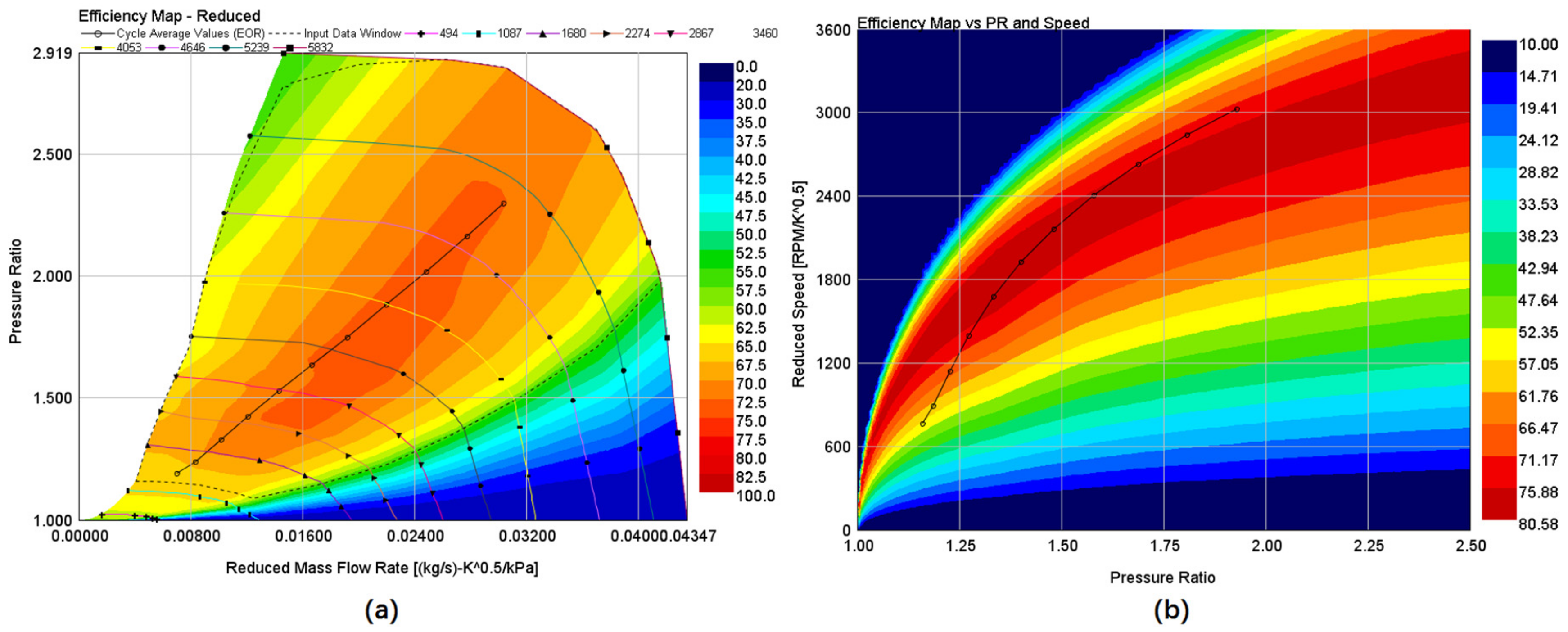
Figure 3.
Schematic of the organic Rankine cycle (ORC) system.

Figure 4.
The ICE-ORC combined model in GT-POWER integrated with the control strategy designed in MATLAB/Simulink.
Figure 4.
The ICE-ORC combined model in GT-POWER integrated with the control strategy designed in MATLAB/Simulink.
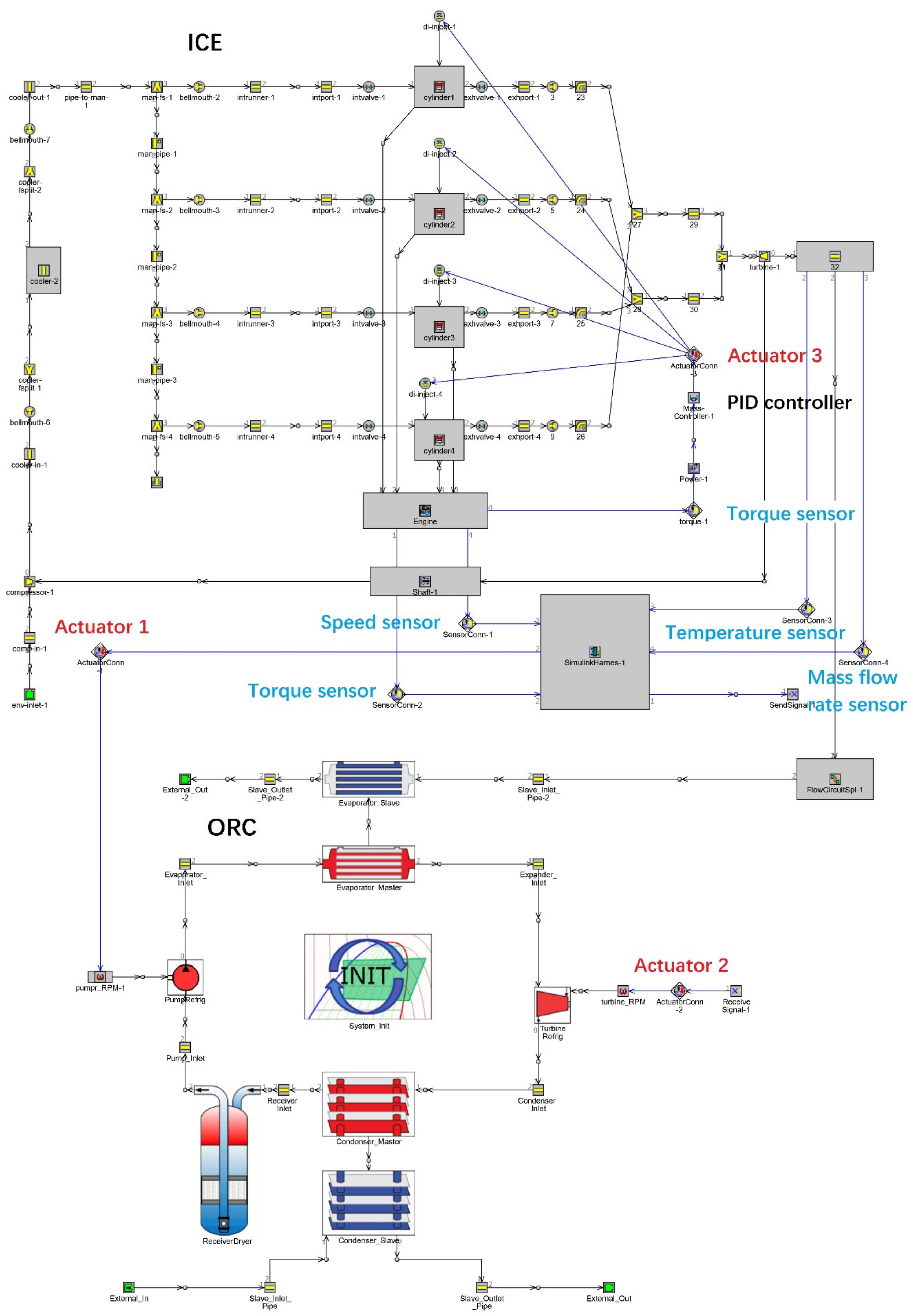
Figure 5.
Results of the ORC system when the engine operates under the rated power condition: (a) The net power output and (b) the thermal efficiency.
Figure 5.
Results of the ORC system when the engine operates under the rated power condition: (a) The net power output and (b) the thermal efficiency.

Figure 6.
Influences of the mass flow rate and the evaporation pressure on the ORC system performance: (a) The net power output, (b) the temperature at the outlet of the evaporator, and (c) the superheat degree.
Figure 6.
Influences of the mass flow rate and the evaporation pressure on the ORC system performance: (a) The net power output, (b) the temperature at the outlet of the evaporator, and (c) the superheat degree.
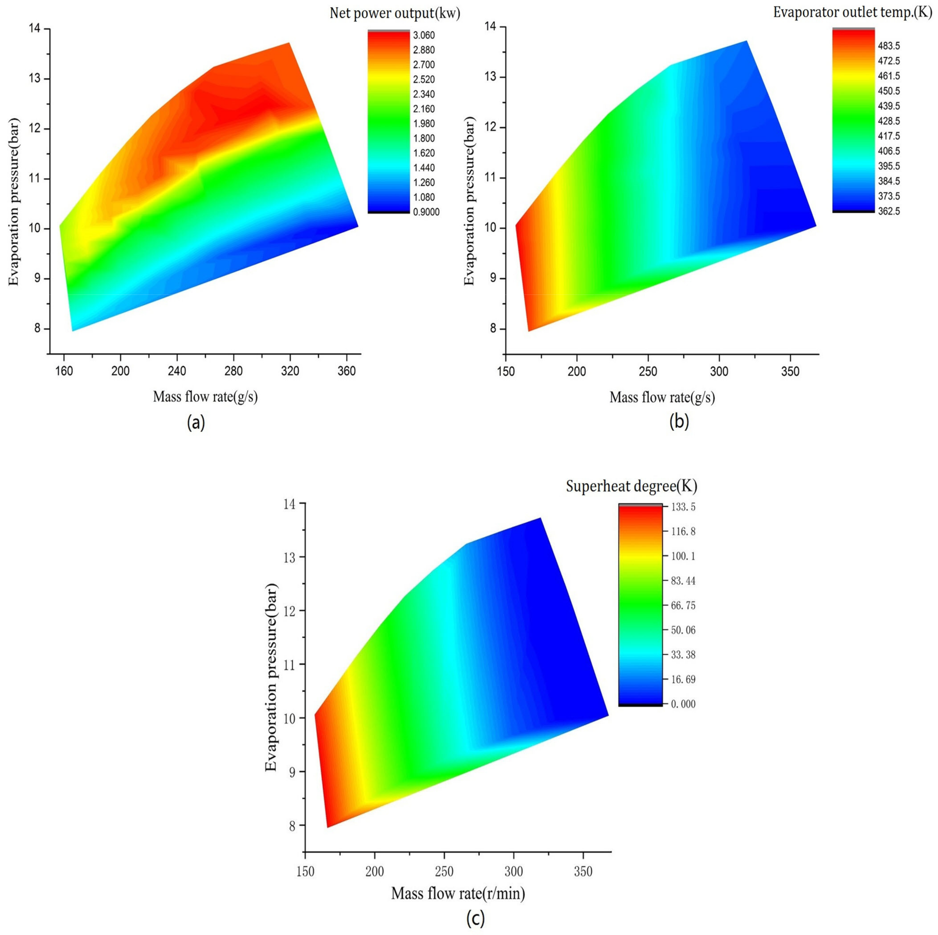
Figure 7.
Influence of the expander efficiency: (a) The net power and (b) the thermal efficiency.
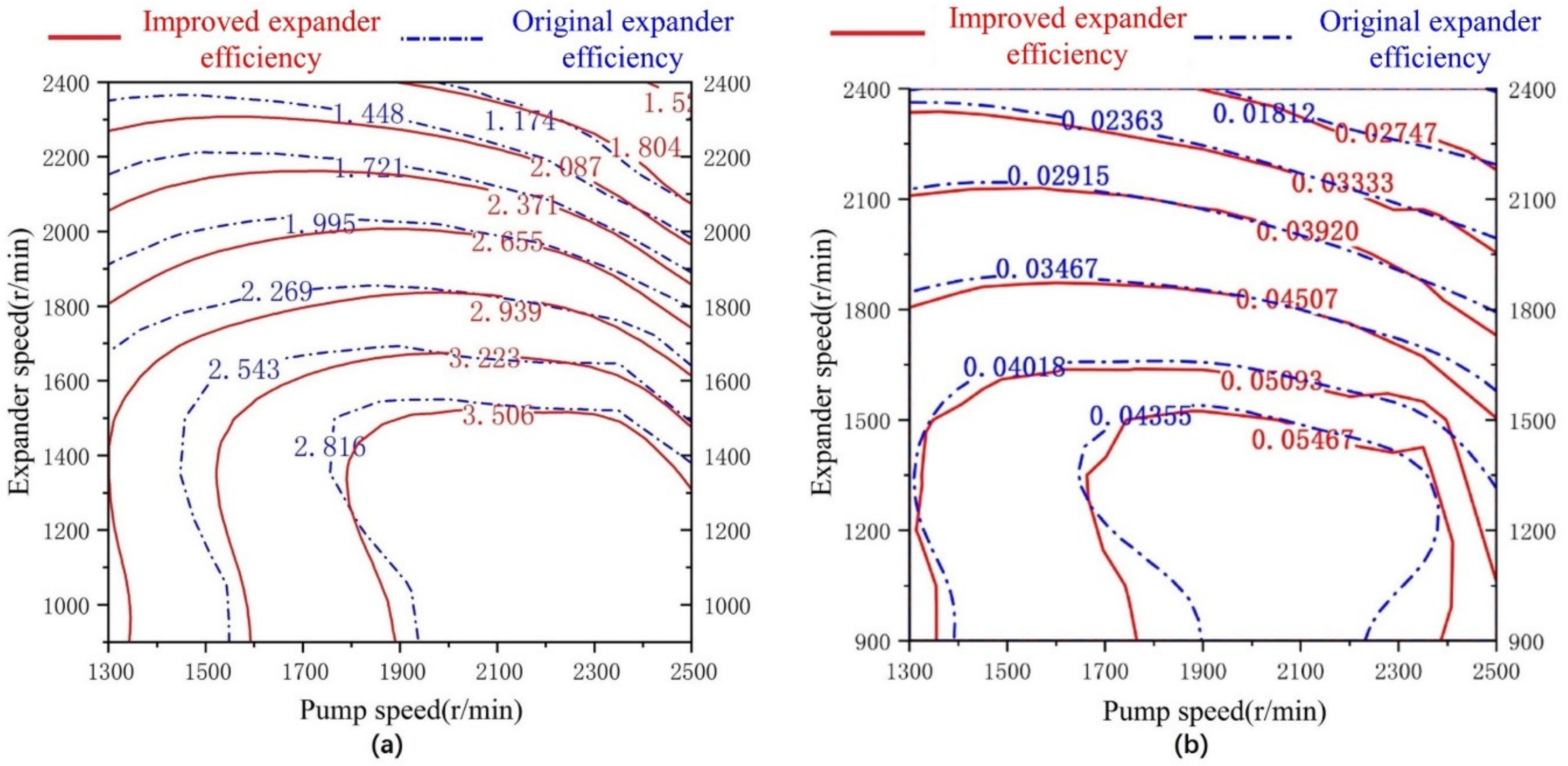
Figure 8.
Results for the net power of the ORC under various engine speeds with a 100% load.

Figure 9.
Results for the net power of the ORC under various engine loads with an engine speed of 3600 r/min.
Figure 9.
Results for the net power of the ORC under various engine loads with an engine speed of 3600 r/min.

Figure 10.
Results for the optimal operation point of the ORC under various engine operation conditions: (a) The pump speed and (b) the expander speed.
Figure 10.
Results for the optimal operation point of the ORC under various engine operation conditions: (a) The pump speed and (b) the expander speed.

Figure 11.
Results for the transient simulation of the ICE-ORC combined system: (a) The vehicle speed, (b) the engine speed, (c) the engine torque, and (d) the expander power output.
Figure 11.
Results for the transient simulation of the ICE-ORC combined system: (a) The vehicle speed, (b) the engine speed, (c) the engine torque, and (d) the expander power output.

Table 1.
The main technical parameters of the BJ493ZLQ3 engine.
| Parameter | Value | Unit |
|---|---|---|
| Displacement | 2.771 | L |
| Rated power | 85 | kW |
| Max. torque | 280 | N·m |
| Bore | 93 | mm |
| Stroke | 102 | mm |
| Compression ratio | 17.4 | – |
Table 2.
The main parameters of the evaporator.
| Parameter | Value | Unit |
|---|---|---|
| Tube length | 850 | mm |
| Tube diameter | 12 | mm |
| Tube number | 90 | mm |
| Shell diameter | 150 | mm |
| Path number | 1 | — |
Table 3.
The main parameters of the condenser.
| Parameter | Value | Unit |
|---|---|---|
| Plate length | 300 | mm |
| Plate width | 200 | mm |
| Channel height | 3 | mm |
| Channel number | 45 | — |
Table 4.
The engine performance under the rated power condition.
| Parameter | Value | Unit |
|---|---|---|
| Engine speed | 3600 | r/min |
| Power | 83.0 | kW |
| Torque | 220.2 | N·m |
| Fuel consumption | 260.2 | g/kW·h |
| Thermal efficiency | 32.2 | % |
| Exhaust mass flow | 185.6 | g/s |
| Exhaust temperature | 757 | K |
| Heat addition | 75.6 | kW |
© 2019 by the authors. Licensee MDPI, Basel, Switzerland. This article is an open access article distributed under the terms and conditions of the Creative Commons Attribution (CC BY) license (http://creativecommons.org/licenses/by/4.0/).
Share and Cite
MDPI and ACS Style
Liu, T.; Wang, E.; Meng, F.; Zhang, F.; Zhao, C.; Zhang, H.; Zhao, R. Operation Characteristics and Transient Simulation of an ICE-ORC Combined System. Appl. Sci. 2019, 9, 1639. https://doi.org/10.3390/app9081639
AMA Style
Liu T, Wang E, Meng F, Zhang F, Zhao C, Zhang H, Zhao R. Operation Characteristics and Transient Simulation of an ICE-ORC Combined System. Applied Sciences. 2019; 9(8):1639. https://doi.org/10.3390/app9081639
Chicago/Turabian StyleLiu, Tong, Enhua Wang, Fanxiao Meng, Fujun Zhang, Changlu Zhao, Hongguang Zhang, and Rui Zhao. 2019. "Operation Characteristics and Transient Simulation of an ICE-ORC Combined System" Applied Sciences 9, no. 8: 1639. https://doi.org/10.3390/app9081639
Note that from the first issue of 2016, this journal uses article numbers instead of page numbers. See further details here.