Article

Case Studies for Non-Detection of Islanding by Grid-Connected In-Parallel Photovoltaic and Electrical Energy Storage Systems Inverters

1
Photovoltaics Laboratory, New and Renewable Energy Institute, Korea Institute of Energy Research, Daejeon 34129, Korea
2
Department of Safety Engineering, Seoul National University Science and Technology, Seoul 01811, Korea
*
Author to whom correspondence should be addressed.
Appl. Sci. 2019, 9(5), 817; https://doi.org/10.3390/app9050817
Submission received: 4 January 2019 / Revised: 20 February 2019 / Accepted: 20 February 2019 / Published: 26 February 2019
(This article belongs to the Special Issue Smart PV Generation with Energy Storage)

Abstract

:
In Korea, there is a rule for Renewable Energy Certification with weighting 5.0, to expand grid linkage capacity and to improve the stability of the grid to accommodate photovoltaic (PV) systems in a distributed power system. Due to this rule, many power companies and operators are trying to install electrical energy storage systems that are able to operate in conjunction with PV system power. These systems operate in parallel at the same grid connection point. This paper presents the results of case studies on the failure to detect islanding operation. Test evaluation devices that could be bi-directionally charged and discharged were implemented for an islanding detection test. Testing was conducted under a variety of operating conditions. When a single inverter was operated under the islanding condition, it was stably stopped within 0.5 s using the Korean grid-code standard. However, when two inverters were operated at the same time under the islanding condition, islanding detection failed and the two inverters continued to feed the connected RLC (resistor, inductor, capacitor) loads in the isolated section known as an island. Different algorithms used by PCS (power conversion system) manufacturers to detect islanding might cause this phenomenon. Therefore, it is necessary for a new PCS test standard to detect islanding.

1. Introduction

As the supply of renewable energy is expanding globally, the amount of distributed power sources (e.g., solar photovoltaic (PV) and wind power) connected to the power grid is also rapidly increasing [1]. In addition, a number of studies related to distributed power connections have been conducted [2,3,4,5,6,7]. The inclusion of distributed power sources such as PV and wind power [8,9,10] could degrade power quality due to fluctuations of their output power. It is expected that the use of electrical energy storage systems will be increased to resolve adverse effects on the grid as the use of distributed power increases [11,12,13,14]. Generally, an electrical energy storage system (EESS) is used to improve power system stability and improve the quality of distributed power systems [15,16,17]. The intended benefits from installing an EESS include peak cutting, load shifting, fluctuation offset of the distributed power output, creating a power reserve, and demand management. In particular, when the utility system is disconnected to create a distributed system, EESS can contribute to the voltage and frequency stability of the power transmitted in the utility grid [18,19].
As shown in Table 1, in Korea, the ‘REC (Renewable Energy Certificate) weight 5.0’ rule is operating to expand the grid linkage capacity for PV systems and to improve the stability of the power system by reducing fluctuations. And as shows Figure 1 this rule grants five times the REC weighting to the output electrical energy discharged from EESS after 4:00 p.m. when the EESS is charged by electrical energy produced by a PV system from 10:00 a.m. to 4:00 p.m. [20]. Power generation companies operating PV plants are planning to install EESSs linked to PV systems, and the demand for EESSs is expected to increase.
The islanding of grid-connected distributed systems such as PV, EESS, and wind power occurs when a section of the utility system containing such distributed systems are disconnected from the main utility voltage source [22].
Anti-islanding papers given at the Institute of Electrical and Electronics Engineer (IEEE) conferences and published in journals have increased rapidly between 1989 and 2012: the number of published papers was six in 2002 and seventy-four in 2012. This shows that there is increasing interest in the detection of islanding [23,24]. In addition, there is growing interest in the safety of micro-grid and distributed power systems regarding voltage and frequency variations [25,26]. Distributed systems continue to feed the power utility lines in the isolated sections known as islands [27,28]. Such isolated islands are dangerous to people who consider the load inactive and it cause serious accidents to power system at the next power-up [29]. In particular, operators may suffer serious problems when exposed to the island circuit during grid repair operations. Moreover, there is a risk of damage to the PV and EESS if the island is reconnected without synchronization [30]. Therefore, it is clear that the islanding situation requires proper control to perform a stable operation of distributed power systems [31].
The inverter of a distributed system has an algorithm (e.g., frequency detection method, reactive power injection-detection method) that can detect an isolated island [32]. In PV inverters, the methods used to detect islanding fall into three categories: passive islanding, active islanding, and remote islanding. Among the most popular standards for anti-islanding are IEEE 929-2000, IEC62116, IEE1547, VDE0126-1-1, and AS 4777.3-2005. Table 2 shows each standard with its quality factor, required islanding detection time, normal frequency, and voltage operation range.
However, when more than one inverter is connected to an inverter in parallel, even if each inverter has an anti-islanding detection function, the detection of islanding might fail due to the interaction of one inverter with the other. When all the energy produced by a PV system is only charging an EESS, and no utility power source is involved, the inverters might be operating as an isolated island. The islanding detection method used by an inverter of a distributed system determines the state of the utility power lines by injection of a disturbance signal into the inverter to change the frequency or voltage.
When one inverter changes the frequency or voltage signal to detect an isolated island, the other inverter might fail to detect islanding if its signal is added to the signal of another inverter and they offset each other. In this paper, experimental devices capable of simulating a PV power source and energy storage system were constructed. Islanding detection of individual inverters (PV inverter or EESS inverter) was tested, and when the two inverters (PV inverter and EESS inverter) were connected in parallel, islanding detection was tested. In particular, the EESS was tested for an islanding operation situation in the charging mode, which is operated in connection with the PV system and the power grid. Especially, islanding detection failed depending on the charging capacity of the EESS. Because EESS has charge and discharge modes, it is different from situations in which PV inverters are parallel connected to the power grid. In other words, the EESS not only releases electricity energy but also acts as an R-load. Therefore, in this paper, this study was carried on islanding detection when the PV inverter and EESS inverter (charge/discharge mode) operate under islanding in parallel connection to the power grid.

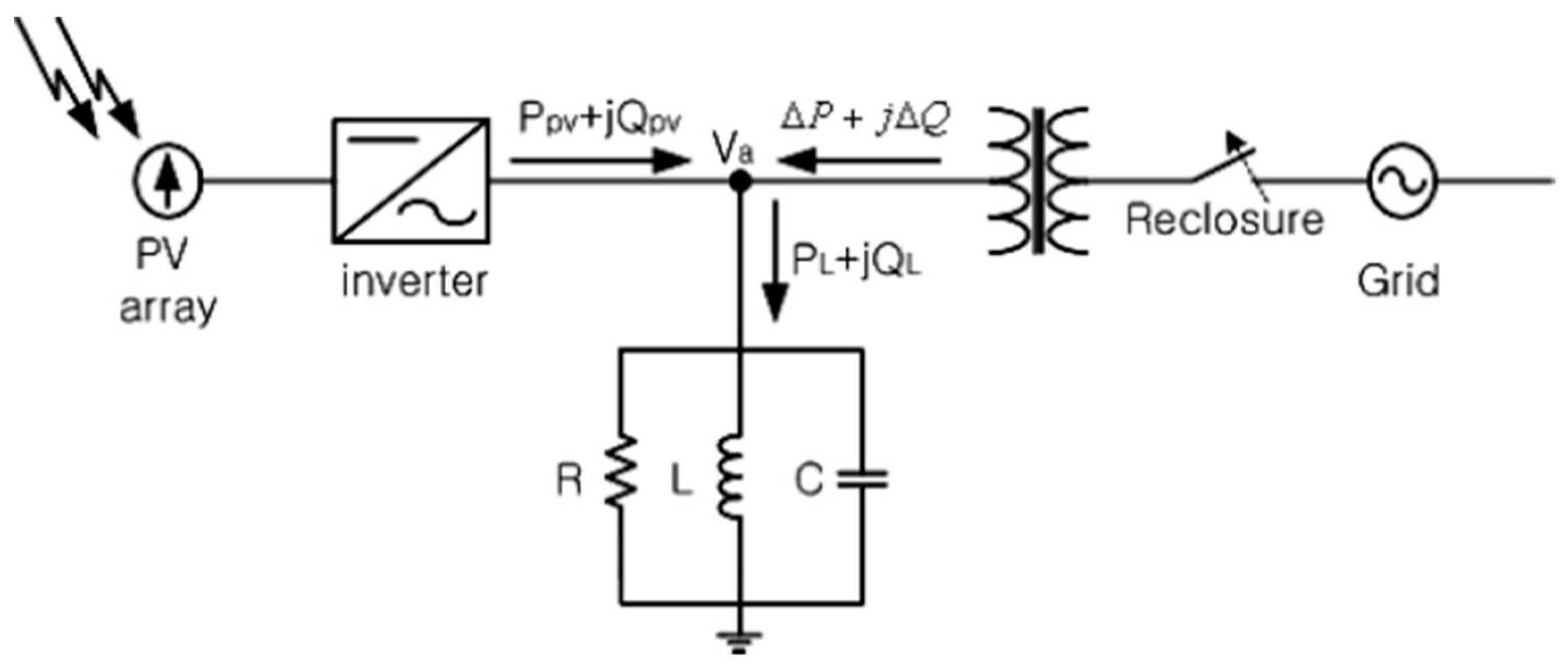
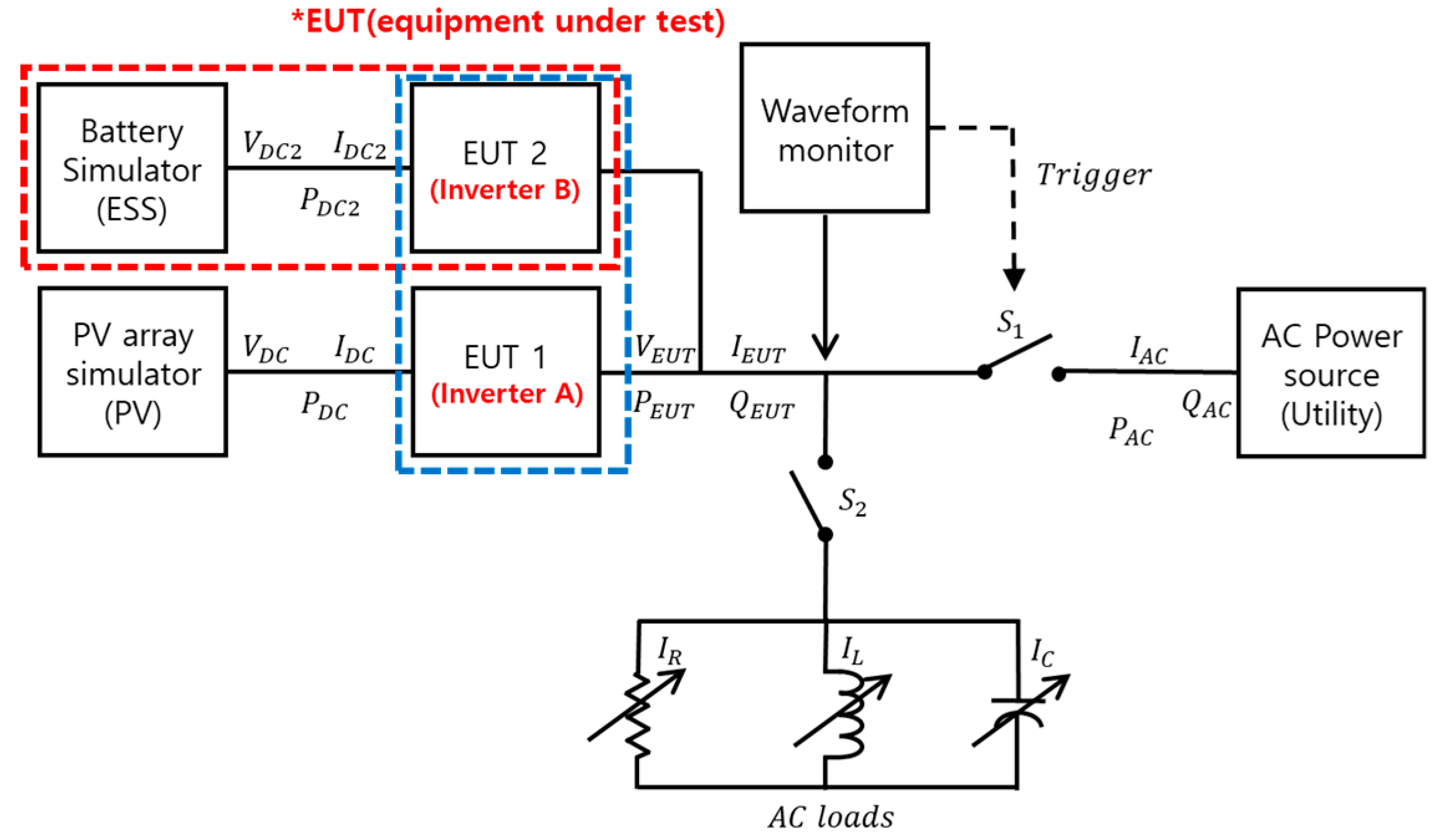
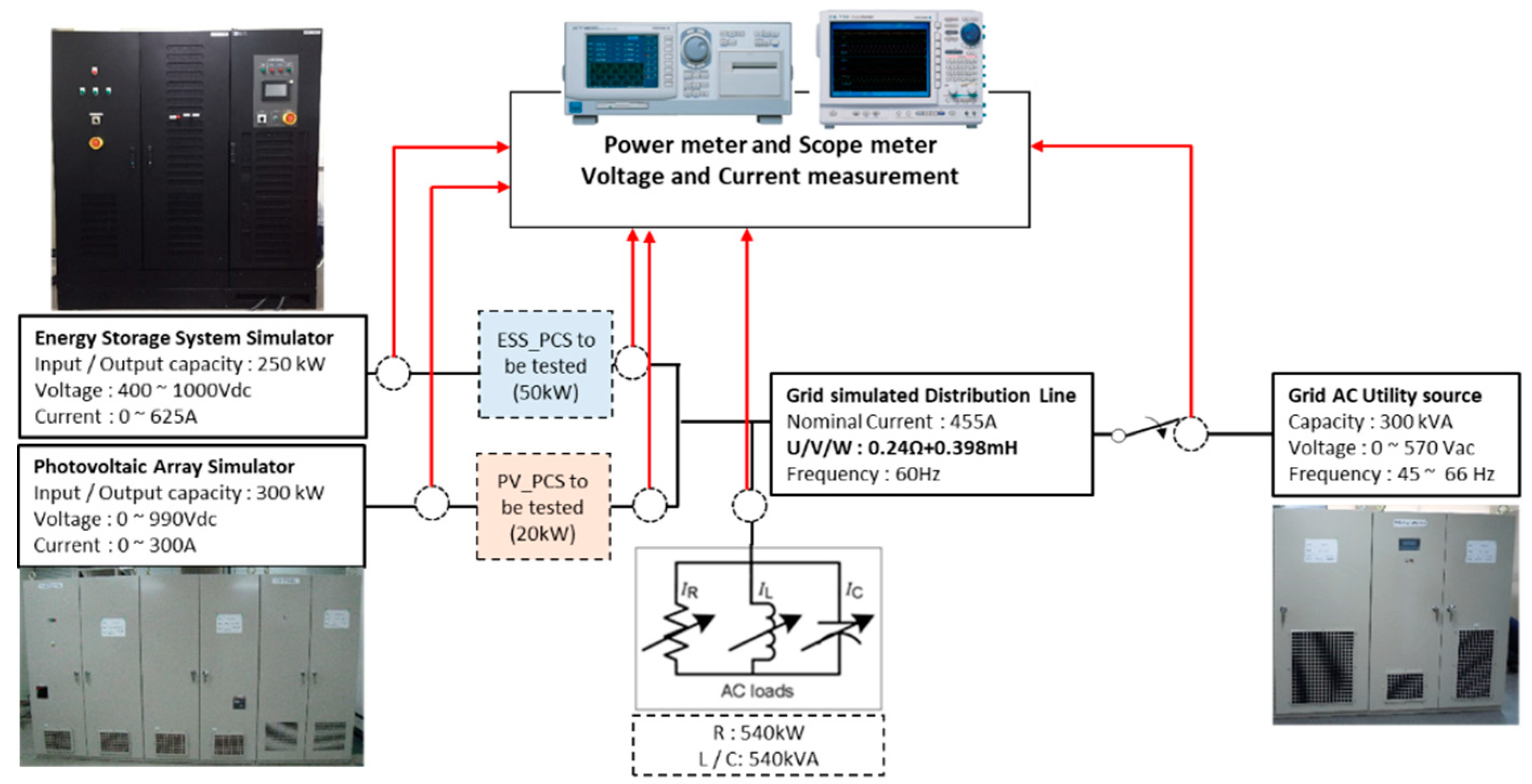
2. Test Procedure for Islanding Detect

The standards for anti-islanding tests for PV system inverters are IEC61727:2004 (photovoltaic systems characteristics of the utility interface) and IEC 62116 (test procedure for islanding prevention measures). These standards describe the safety test methods for PV inverters, including islanding prevention. Figure 2 shows a circuit configuration of a test device for islanding detection. The test was carried out according to various test conditions set in the standards regarding the ratio of active power to reactive power.
IEC 62116 is a test standard for islanding detection of one PV inverter. However, when PV and EESS are connected to a grid, the PV inverter and EESS inverter are used together. In this paper, we simulated this situation and experimented by connecting two inverters (PV and EESS) in parallel based on IEC 62116. Also, among test condition A of IEC 62116, the experiment was conducted using the (0,0) condition. The configuration of the experimental equipment consisted of one test inverter (EESS) and one DC power source in parallel, diagrammed in Figure 3. The generator and loads could be any combination of customer-owned and utility-owned.
In this work, the experimental circuit was configured as shown in Figure 3 to test islanding detection while two inverters (PV inverter and EESS inverter) were operated. The DC power source, which can be operated in constant voltage (CV) mode (red dotted line), can supply power and consume the load like a battery system. Tests were carried out under the condition that the quality factor was one, not under a variety of conditions. Equation (1) shows how the quality factor is calculated:
Q f = Q L × Q C P R
Figure 4 shows the specifications and configuration of the experimental equipment used for islanding detection testing. The power meter measured the active power from the test inverters and the active and reactive power consumed by the RLC loads. The scope meter measured and recorded the waveforms for voltages, currents and frequency at the test-inverter output terminals and the waveform of the voltage of utility power line. The experiment was carried out when the test inverters were in islanding condition. The switch of the main power line was turned off in this state and the waveforms were measured and recorded. Then, it was checked whether the inverter stopped normally within 0.5 seconds according to the Korean grid code. The two test inverters used in the testing were commercial products and the specifications of the inverters are described in Table 3. Table 4 shows each test case.
Experimental cases 1–2 were tests to check whether each inverter could detect an islanding operation with an output power of 20 kW. In experimental case 3, when the PV inverter and EESS inverter supplied power to the grid line (including the loads), the function of island detection was tested. In case 4, the PV inverter supplied power to the grid and the EESS inverter charged its batteries (in the energy storage-system simulator in Figure 4). Because the PV inverter and EESS inverter were operated in parallel at the grid connection point, the characteristics of islanding detection had to be tested under various conditions according to the active power of the inverters.

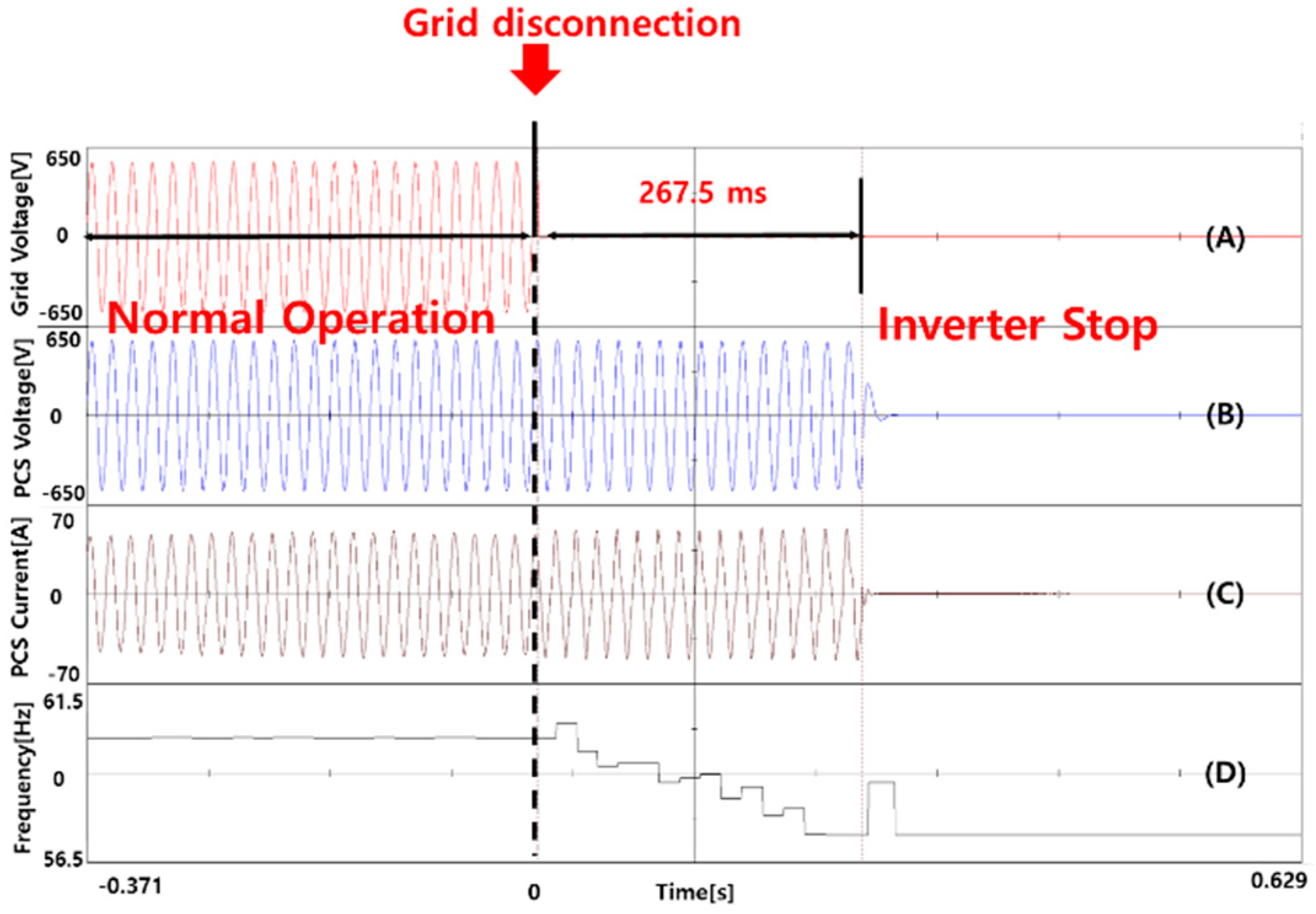
3. Experimental Results

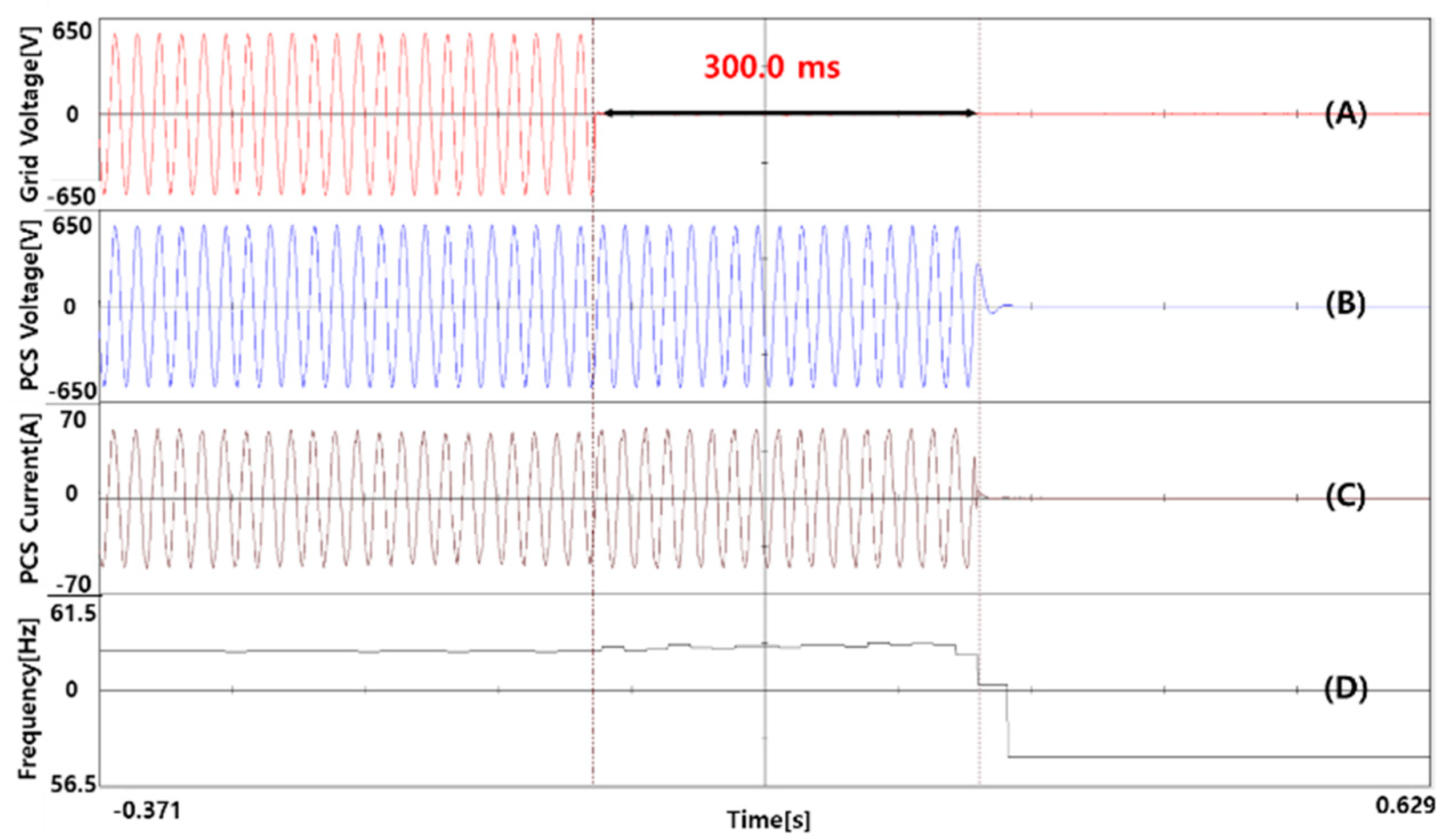
3.1. Islanding Detection Test for the Individual Inverter

Figure 5 shows the test results for cases 1 and 2 in Table 4. In Figure 5, the waveform (A) is the line-to-line voltage of one phase of the grid utility section, (B) is the output voltage of the inverter, (C) is the output current of the inverter, and (D) is the frequency. Figure 5 shows the resultant waveform for islanding detection testing under the 20 kW rated power of the PV inverter. The load capacities were 20 kW for R-load, −20 kVA for L-load, and 20 kVA for C-load at that time.
After turning off the grid side switch, the time until the PV inverter stopped was calculated using the scope waveform. Because the magnitude of the output current of the test inverter was the same in all phases, the waveform of the voltage and current for only one phase was measured. The test results for the PV inverter showed approximately 267.5 ms for the inverter to stop. The PV inverter stopped normally within 0.5 s of the grid code in Korea. The method of detecting islanding in the PV inverter might be estimated using a frequency detection algorithm to detect the frequency of every cycle. The frequency waveform changed to 56.55 Hz from 59.9 Hz in the previous cycle and then decreased continuously to reach the cutoff frequency.
Figure 6 shows the resultant waveform for testing under EESS inverter-operated discharging mode with 20 kW output power to the grid utility section. The RLC loads were the same as for the PV inverter testing. The time taken for the inverter to stop was approximately 300 ms. In the case of the EESS inverter, the method of detecting whether the frequency was changed was by injecting reactive power at every specific period. The injection period for reactive power of the EESS inverter was about 300 ms, such as for the frequency waveform in Figure 6. In comparison to the previous test results, the islanding detection method of the inverters of manufacturer A and B was different.

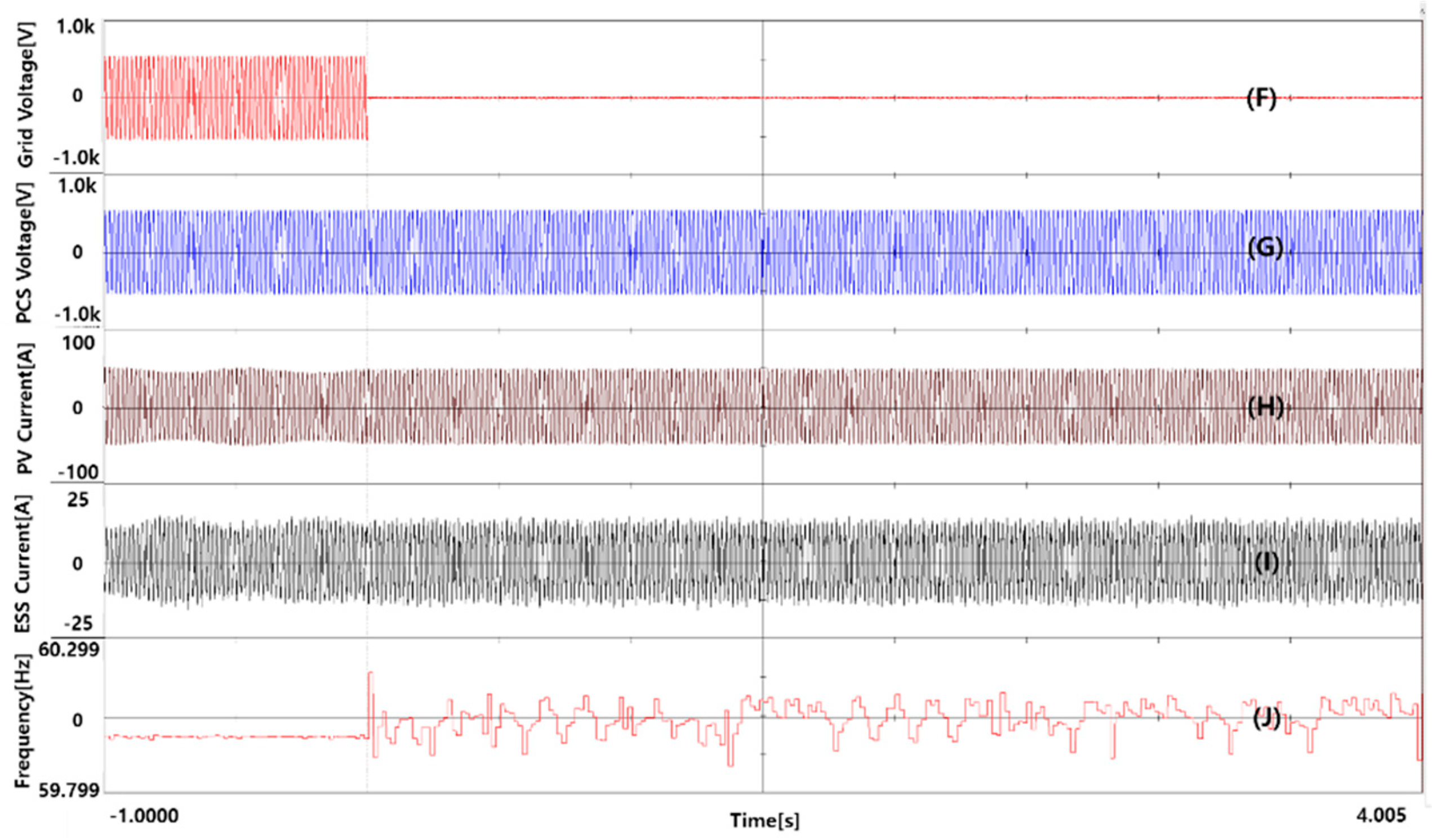
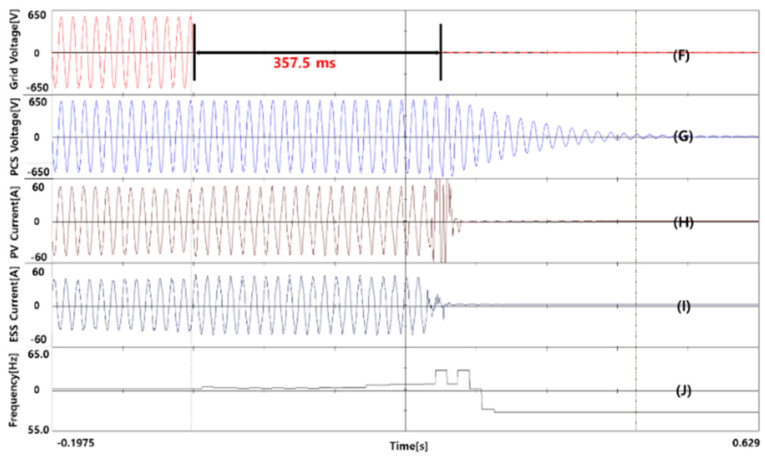
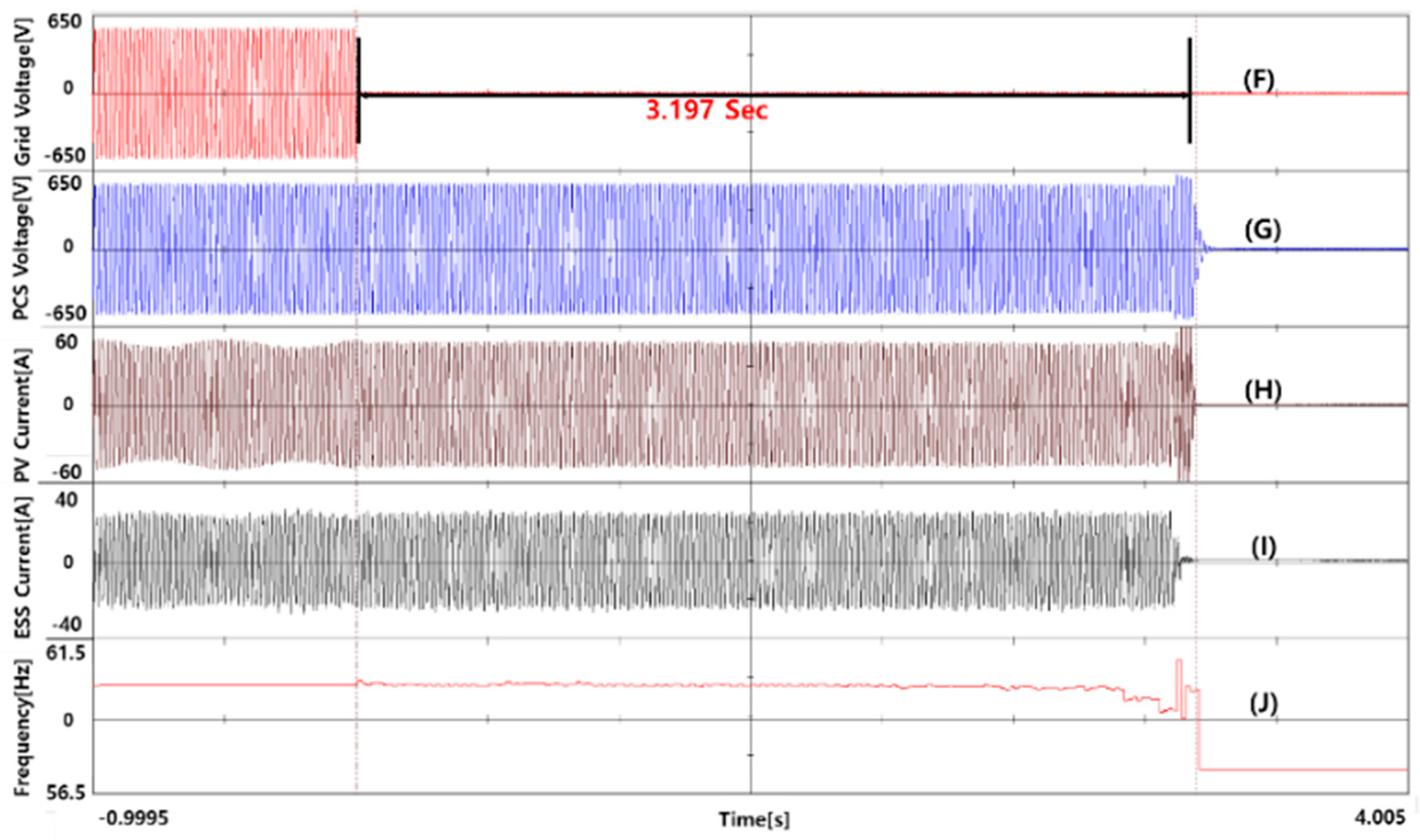
3.2. Islanding Detection Testing with Parallel Operation of Two Inverters

Figure 7 shows the experimental results for case 3 in Table 4. (A) is the waveform for the voltage of the grid utility side, (B) is the waveform for the inverter output voltage, (C) is the waveform for the inverter output current of manufacturer A, (D) is the waveform for the inverter output current of manufacturer B, and (E) is the waveform for frequency. For the islanding detection testing, the PV inverter was operated at its rated power of 20 kW, and the inverter for the EESS was operated simultaneously in a 20 kW discharge mode. Then, the R-load (40 kW), L-load (−40 kVA), and C-load (40 kVA) were connected in an islanding condition. Although the switch of the grid utility was shut off, the inverters failed to detect the islanding and continuously supplied power to the RLC loads. Therefore, the inverters were manually stopped. The frequency waveform in Figure 7 shows that the two inverter frequencies were combined under the islanding condition. The EESS inverter injected reactive power to detect islanding approximately every 350 ms and this showed that the frequency fluctuated. The islanding detection failed because the frequency change value fluctuated within 5% of the cutoff frequency.
The algorithm and period for islanding detection are generally different for each inverter manufacturer. Even if a frequency adjustment or reactive power injection for islanding detection was performed at every specific period by each inverter, the islanding detection could still fail because the cutoff frequency range was not reached. It is possible to change this onsite by adjusting the islanding detection gain value of the specific inverter. However, if the gain value is large, there is an influence on THD (Total Harmonic Distortion) or flicker occurs. Therefore, to connect a grid utility safely, it is necessary to develop a proper algorithm that can detect islanding while several inverters operate in parallel at the same connection point.
Figure 8 shows the waveforms of the experimental results for islanding detection when the PV inverter was operated at a rated power of 20 kW and the EESS inverter was operated in charging mode at 20 kW. The RLC capacities were 0 kW of R-load, −20 kVA of L-load, and 20 kVA of C-load. The test time for anti-islanding of the inverters was recorded when islanding occurred after the circuit breaker of the grid side shut off. The time until the inverters stopped was approximately 357.5 ms and the inverter normally detected the islanding. Islanding detection was possible when the output power of the PV inverter was the same as the charging power of the EESS inverter. In this case, the PV inverter stopped due to an overcurrent error from an insulated-gate bipolar transistor (IGBT) component.
Figure 9 shows the resulting waveforms when the PV inverter was operated at its rated power of 20 kW and the EESS inverter was operated at 10 kW output power in charging mode. This experiment simulated a state with a power load of 10 kW because the EESS inverter operated as if it was consuming the R-load. The RLC load capacities were 10 kW of R-load, −20 kVA of L-load, and 20 kVA of C-load. The time to stop was 3.197 s and the inverters failed to detect islanding within this time. Case 5 was different from case 4 because there was an R-load. It is estimated that the islanding detection time was later than case 4 due to the R-load. When the EESS was in charge mode, it functioned as an electronic load and consumed the power generated by the PV system; the R-load also consumed the power of the PV system.
Figure 10 shows the resulting waveforms when the PV inverter was operated at a rated power of 20 kW and the EESS inverter operated in charging mode at 5 kW. From the experimental results, the inverters were in continuous operation and had to be stopped manually for safety. It was confirmed through this experiment that islanding detection of test inverters was impossible when the PV inverter was operating and the EESS inverter was charged using some of the energy that the PV inverter discharged. The measuring frequency was continuously changed within the reference range during islanding based on the frequency waveforms in Figure 10.

4. Conclusions

In this work, testing for islanding detection was conducted when a PV system and EESS were operated in parallel at the same grid connection point. In the test of islanding detection by one inverter, the inverter detected the islanding and stopped stably. However, when two inverters were supplying power to the grid utility, the islanding detection failed and the inverters operated continuously. Generally, the EESS inverter in charging mode operates as the R (Resistance) load. When the EESS inverter was charging with energy supplied from the PV inverter, islanding was detected. However, this caused an overcurrent error of the PV inverter IGBT. When the EESS inverter was charging with some of the energy supplied by the PV inverter, the inverters failed to detect islanding. In some cases, the EESS inverter does not apply the algorithm for islanding detection while operating in charging mode, so the inverter could fail to detect islanding. From the experimental results, islanding detection could fail due to the different methods and measuring periods used by each manufacturer of inverters for detecting islanding states. The conclusions can be summarized as follows.
(1)
When two inverters by different manufacturers were operated in parallel at the same grid connection point, the inverters failed to detect islanding and supplied power continuously to the load or grid utility. Because the method and detection period for islanding detection of each manufacturer are different, detection can fail.
(2)
When the EESS inverter was charging with all the energy supplied by the PV inverter, islanding was detected. However, the PV inverter stopped due to an overcurrent error of the IGBT.
(3)
When the EESS inverter was charging with only some of the energy supplied from the PV inverter, islanding was not detected.
(4)
Because the EESS inverter can operate in parallel with other inverters of distributed power sources, an effective algorithm for islanding detection has to be applied in charging mode.
It is necessary to make a new test standard for islanding detection because in some cases two inverters in parallel might not detect an islanding.

Author Contributions

J.R.L. wrote the main part of the paper, in particular, the results of the experiment were analyzed. H.M.H. and H.-J.S. provided technical ideas and assistance in establishing the experiment. W.G.S. and Y.S.J. established the research direction of the paper and suggested a method for conducting the experiment. Y.-C.J. and G.H.K. analyzed the data using the paper and provided important comments. S.W.K. reviewed and revised the overall content of the paper.

Acknowledgments

This work was supported by a grant from the Standardization Certification of Korea Energy Agency (KEA) funded by the Ministry of Trade, Industry and Energy, Republic of Korea (Nos. 71000145, 71000106).

Conflicts of Interest

The authors declare no conflict of interest.

References

  1. Cha, J.-H.; Park, K.-W.; Ahn, H.-S.; Kwon, K.-M.; Oh, J.-H.; Mahirane, P.; Kim, J.-E. Overvoltage Protection Controller Design of Distributed Generation Connected to Power Grid Considering Islanding Condition. J. Electr. Eng. Technol. 2018, 13, 599–607. [Google Scholar]
  2. Ito, Y.; Yang, Z.; Akagi, H. DC microgrid based distribution power generation system. In Proceedings of the 4th International Power Electronics and Motion Control Conference, IPEMC 2004, Xi’an, China, 14–16 August 2004; IEEE: Piscataway, NJ, USA, 2004; Volume 3. [Google Scholar]
  3. Doyle, M.T. Reviewing the impacts of distributed generation on distribution system protection. In Proceedings of the 2002 IEEE Power Engineering Society Summer Meeting, Chicago, IL, USA, 21–25 July 2002; IEEE: Piscataway, NJ, USA, 2002; Volume 1. [Google Scholar]
  4. Yang, H.; Lu, L.; Zhou, W. A novel optimization sizing model for hybrid solar-wind power generation system. Sol. Energy 2007, 81, 76–84. [Google Scholar] [CrossRef]
  5. Shin, S.S.; Oh, J.S.; Jang, S.H.; Chae, W.K.; Park, J.H.; Kim, J.E. A fault analysis on AC microgrid with distributed generation. J. Electr. Eng. Technol. 2016, 11, 1600–1609. [Google Scholar] [CrossRef]
  6. Guerriero, P.; Coppola, M.; Di Napoli, F.; Brando, G.; Dannier, A.; Iannuzzi, D.; Daliento, S. Three-phase PV CHB inverter for a distributed power generation system. Appl. Sci. 2016, 6, 287. [Google Scholar] [CrossRef]
  7. Cho, S.M.; Shin, H.S.; Park, J.H.; Kim, J.C. Distribution system reconfiguration considering customer and DG reliability cost. J. Electr. Eng. Technol. 2012, 7, 486–492. [Google Scholar] [CrossRef]
  8. Liu, H.; Li, D.; Liu, Y.; Dong, M.; Liu, X.; Zhang, H. Sizing Hybrid Energy Storage Systems for Distributed Power Systems under Multi-Time Scales. Appl. Sci. 2018, 8, 1453. [Google Scholar] [CrossRef]
  9. Blaabjerg, F.; Teodorescu, R.; Liserre, M.; Timbus, A.V. Overview of control and grid synchronization for distributed power generation systems. IEEE Trans. Ind. Electron. 2006, 53, 1398–1409. [Google Scholar] [CrossRef]
  10. Liserre, M.; Teodorescu, R.; Blaabjerg, F. Stability of photovoltaic and wind turbine grid-connected inverters for a large set of grid impedance values. IEEE Trans. Power Electron. 2006, 21, 263–272. [Google Scholar] [CrossRef]
  11. Lasseter, B. Microgrids [distributed power generation]. In Proceedings of the IEEE Power Engineering Society Winter Meeting, Columbus, OH, USA, 28 January–1 February 2001; IEEE: Piscataway, NJ, USA, 2001; Volume 1. [Google Scholar]
  12. Prodanovic, M.; Green, T.C. High-quality power generation through distributed control of a power park microgrid. IEEE Trans. Ind. Electron. 2006, 53, 1471–1482. [Google Scholar] [CrossRef]
  13. Lasseter, R.H. Microgrids and distributed generation. J. Energy Eng. 2007, 133, 144–149. [Google Scholar] [CrossRef]
  14. Pogaku, N.; Prodanovic, M.; Green, T.C. Modeling, analysis and testing of autonomous operation of an inverter-based microgrid. IEEE Trans. Power Electron. 2007, 22, 613–625. [Google Scholar] [CrossRef]
  15. Divya, K.C.; Østergaard, J. Battery energy storage technology for power systems—An overview. Electr. Power Syst. Res. 2009, 79, 511–520. [Google Scholar] [CrossRef]
  16. Roberts, B.; McDowall, J. Commercial successes in power storage. IEEE Power Energy Mag. 2005, 3, 24–30. [Google Scholar] [CrossRef]
  17. Joseph, A.; Shahidehpour, M. Battery storage systems in electric power systems. In Proceedings of the IEEE Power Engineering Society General Meeting, Montreal, QC, Canada, 18–22 June 2006; IEEE: Piscataway, NJ, USA, 2006. [Google Scholar]
  18. Husein, M.; Hau, V.B.; Chung, I.Y.; Chae, W.K.; Lee, H.J. Design and Dynamic Performance Analysis of a Stand-alone Microgrid—A Case Study of Gasa Island, South Korea. J. Electr. Eng. Technol. 2007, 12, 1777–1788. [Google Scholar]
  19. Kim, J.Y.; Jeon, J.H.; Kim, S.K.; Cho, C.; Park, J.H.; Kim, H.M.; Nam, K.Y. Cooperative control strategy of energy storage system and microsources for stabilizing the microgrid during islanded operation. IEEE Trans. Power Electron. 2010, 25, 3037–3048. [Google Scholar]
  20. Korea Solar and Energy Storage Market Public. Available online: http://esi.nus.edu.sg/docs/default-source/doc/korea-solar-and-energy-storage-market_public.pdf?sfv rsn=2 (accessed on 25 February 2019).
  21. KEA-Korea Energy Agency. Available online: http://www.energy.or.kr/renew_eng/new/standards.aspx (accessed on 25 February 2019).
  22. Choi, J.S.; Ko, J.S.; Chung, D.H. Development of Novel Algorithm for Anti-Islanding of Grid-Connected PV Inverter. J. Korean Inst. Illum. Electr. Install. Eng. 2011, 25, 76–86. [Google Scholar]
  23. Ahmad, K.N.; Selvaraj, J.; Rahim, N.A. A review of the islanding detection methods in grid-connected PV inverters. Renew. Sustain. Energy Rev. 2013, 21, 756–766. [Google Scholar] [CrossRef]
  24. Yu, B.; Matsui, M.; Yu, G. A review of current anti-islanding methods for photovoltaic power system. Sol. Energy 2010, 84, 745–754. [Google Scholar] [CrossRef]
  25. Kim, J.Y.; Kim, S.K.; Jeon, J.H. Coordinated state-of-charge control strategy for microgrid during islanded operation. In Proceedings of the 2012 3rd IEEE International Symposium on Power Electronics for Distributed Generation Systems (PEDG), Aalborg, Denmark, 25–28 June 2012; IEEE: Piscataway, NJ, USA, 2012. [Google Scholar]
  26. Kim, J.Y.; Kim, S.K.; Park, J.H. Contribution of an energy storage system for stabilizing a microgrid during islanded operation. J. Electr. Eng. Technol. 2009, 4, 194–200. [Google Scholar] [CrossRef]
  27. Verhoeven, B. Utility Aspects of Grid Connected Photovoltaic Power Systems; International Energy Agency: Paris, France, 1998. [Google Scholar]
  28. Chung, I.Y.; Moon, S.I. A new islanding detection method using phase-locked loop for inverter-interfaced distributed generators. J. Electr. Eng. Technol. 2007, 2, 165–171. [Google Scholar] [CrossRef]
  29. Zamani, R.; Hamedani-Golshan, M.E.; Haes Alhelou, H.; Siano, P.; Pota, H.R. Islanding Detection of Synchronous Distributed Generator Based on the Active and Reactive Power Control Loops. Energies 2018, 11, 2819. [Google Scholar] [CrossRef]
  30. Ding, X.; Crossley, P.A. Islanding detection for distributed generation. In Proceedings of the 2005 IEEE Russia Power Tech, St. Petersburg, Russia, 27–30 June 2005; IEEE: Piscataway, NJ, USA, 2005. [Google Scholar]
  31. Choi, S.S.; Kang, M.K.; Lee, H.D.; Nam, Y.H.; Rho, D.S. A Stable Operation Strategy in Micro-grid Systems without Diesel Generators. J. Electr. Eng. Technol. 2015, 13, 114–123. [Google Scholar]
  32. De Mango, F.; Liserre, M.; Dell’Aquila, A.; Pigazo, A. Overview of anti-islanding algorithms for PV systems. Part I: Passive methods. In Proceedings of the 12th international Power Electronics and Motion Control Conference, EPE-PEMC 2006, Portoroz, Slovenia, 30 August–1 September 2006; IEEE: Piscataway, NJ, USA, 2006. [Google Scholar]
Figure 1. Photovoltaic (PV) system + electrical energy storage system (EESS) Renewable Energy Certificate (REC) weight rule [20].
Applsci 09 00817 g001
Figure 2. Test circuit for islanding detection in a PV inverter.
Applsci 09 00817 g002
Figure 3. Test configuration diagram of two inverters connected to a utility grid in parallel for islanding detection.
Applsci 09 00817 g003
Figure 4. Specification and configuration of the experimental equipment.
Applsci 09 00817 g004
Figure 5. Test results for islanding detect of A (PV inverter).
Applsci 09 00817 g005
Figure 6. Test results for islanding detect of B (ESS inverter).
Applsci 09 00817 g006
Figure 7. Test result of case 3 (PV 20 kW, EESS −20 kW).
Applsci 09 00817 g007
Figure 8. Test result of case 4 (PV 20 kW, EESS +20 kW).
Applsci 09 00817 g008
Figure 9. Test result of case 5 (PV 20 kW, EESS +10 kW).
Applsci 09 00817 g009
Figure 10. Test result of case 6 (PV 20 kW, EESS +5 kW).
Applsci 09 00817 g010
Table 1. The Renewable Energy Certificate (REC) weights of a photovoltaic (PV) system and electrical energy storage system (EESS) in Korea [21].
DivisionREC Weighted ValueInstallation TypeDetailed Criteria
Only PV System1.2If you are on regular groundsLess than 100 kW
1.0From 100 kW
0.7From 3000 kW
1.5Using existing facilities such as a building3000 kW or less
1.0From 3000 kW
1.5Installing floats on the surface of the retainer
PV System + EESS5.0EESS (PV system connection)’16, ’17, 18
Table 2. Reference standards for anti-islanding.
Quality Factor, QfRequired Islanding Detection Time, tNormal Frequency Range,
f (Nominal Frequency, f0)
Normal Voltage Range, V
(% of Nominal Voltage, V0)
IEEE 621161t < 2 s ( f 0 1.5   Hz ) f   and
f ( f 0 + 1.5   Hz )
85 % V 115 %
IEEE 15471t < 2 s 59.3   Hz f 60.5   Hz 88 % V 110 %
IEEE 929-20002.5t < 2 s 59.3   Hz f 60.5   Hz 88 % V 100 %
Japanese standard0 (+rotating machinery)Passive: t < 0.5 s
Active: 0.5 s < t < 1 s
Setting ValueSetting Value
VDE 0126-1-12 t < 0.2   s 47.5   Hz   f 50.2   Hz 80 % V 115 %
AS4777.3-20051 t < 2   s Setting ValueSetting Value
Table 3. Specification of two test inverters.
ProductA (PV Inverter)B (EESS Inverter)
Electrical connection3 phase 4 wires3 phase 4 wires
Nominal power20 kW50 kW
Input/output voltageInput: 300–600 Vdc
Output: 380 Vac
Input: 600–1000 Vdc
Output: 380 Vac
Isolation typeTransformer typeTransformer-less type
Table 4. The description of each test case for inverter output power and load capacity.
CaseTest ConditionsRemarks
1PV inverter operated at 20 kW, ESS PCS offRLC load Capacity 20 kW, 20 kVar
2PV inverter off, EESS PCS operated at 20 kW in discharging modeRLC load Capacity 20 kW, 20 kVar
3PV inverter operated at 20 kW, EESS inverter operated at 20 kW in discharging modeRLC load Capacity 40 kW, 40 kVar
4PV inverter operated at 20 kW, EESS inverter operated at 20 kW in charging modeRLC load Capacity 0 kW, 20 kVar
5PV inverter operated at 20 kW, EESS inverter operated at 10 kW in charging modeRLC load Capacity 10 kW, 20 kVar
6PV inverter operated at 20 kW, EESS inverter operated at 5 kW in charging modeRLC load Capacity 15 kW, 20 kVar

