A Novel Coding Based Dimming Scheme with Constant Transmission Efficiency in VLC Systems


National Digital Switching System Engineering & Technological Research Center, Zhengzhou 450000, China
*
Author to whom correspondence should be addressed.
Appl. Sci. 2019, 9(4), 803; https://doi.org/10.3390/app9040803
Submission received: 24 January 2019
/
Revised: 14 February 2019
/
Accepted: 22 February 2019
/
Published: 25 February 2019
(This article belongs to the Special Issue Optical Communications and Networking: Prospects in Industrial Applications)
Abstract
:Visible light communication (VLC) has attracted tremendous attention due to two functions: communication and illumination. Both reliable data transmission and lighting quality need to be considered when the transmitted signal is designed. To achieve the desired levels of illumination, dimming control is an essential technology applied in VLC systems. In this paper, we propose a block coding-based dimming scheme to construct the codeword set, where dimming control can be achieved by changing the ratio of two levels (ON and OFF) based on on-off keying (OOK) modulation. Simulation results show that the proposed scheme can maintain good error performance with constant transmission efficiency under various dimming levels.
1. Introduction
Recently, light-emitting diode (LED) lighting technology has made significant progress in indoor applications of green lighting [1,2]. Utilizing the fast response characteristic of LEDs, visible light communication (VLC) systems can simultaneously provide high quality illumination and high-speed wireless data transmission [3,4]. As a complementary technique to radio frequency (RF), VLC has several advantages, e.g., huge bandwidth, high rate transmission, excellent security, and immunity to electromagnetic interference [5]. There is no doubt that VLC is becoming an increasingly attractive communication option. Meanwhile, dimming control plays an essential role in indoor VLC systems, where users can maintain the variable dimming levels. Due to ever-increasing energy consumption, the interest in dimming control has further increased. However, dimming control may cause adverse effects on communication. To overcome these challenges, some dimming schemes have been proposed in recent years [6,7,8,9,10,11,12].
Generally, the existing on-off keying (OOK)-based dimming schemes change the ratio of the two levels (ON and OFF) to achieve dimming control. Thus, the average light intensity can be changed to maintain the various brightness demands. In recent years, many works have been carried out to achieve dimming control. The analog dimming scheme [7] adjusts the direct current (DC) bias of the transmitted signal to meet the required dimming levels where light intensity is reduced proportionally to the current. Unfortunately, this approach may change the wavelength of the emitted light, causing a chromaticity shift effect. The variable-OOK (VOOK) scheme proposed in [7] is the combination of OOK and the pulse width modulation (PWM) signal. The inactive portions of the duty cycle are filled by the filler bits with either ones or zeros according to the dimming level. Variable pulse position modulation (VPPM), where 2-PPM is combined with the PWM signal, is responsible for dimming and data transmission. The multiple-PPM (MPPM)-based dimming scheme constructs the codeword set to achieve the theoretical transmission efficiency limit as the codeword length increases [8]. However, the above-mentioned dimming schemes encounter the common problem that the transmission efficiency cannot be fixed under different dimming levels, which may cause a severe effect on data transmission.
In order to solve the problem of the transmission efficiency not being constant under different dimming levels, we propose a block coding-based dimming scheme to achieve data transmission and dimming control simultaneously. Via bitwise AND operation of the block code and dimming code, new codewords are generated to satisfy the dimming requirement. Simulation results show that the proposed scheme can maintain constant transmission efficiency under different dimming levels, and it proves an attractive alternative to the dimming scheme.
The remainder of this paper is organized as follows: In Section 2, the system model of the proposed block coding scheme is given. In Section 3, the implementation of the proposed coding scheme is demonstrated and the construction of the encoding/decoding algorithm is summarized accordingly. In Section 4, simulations are carried out to evaluate the error performance of the proposed scheme. Finally, we conclude our findings in Section 5.
2. System Model
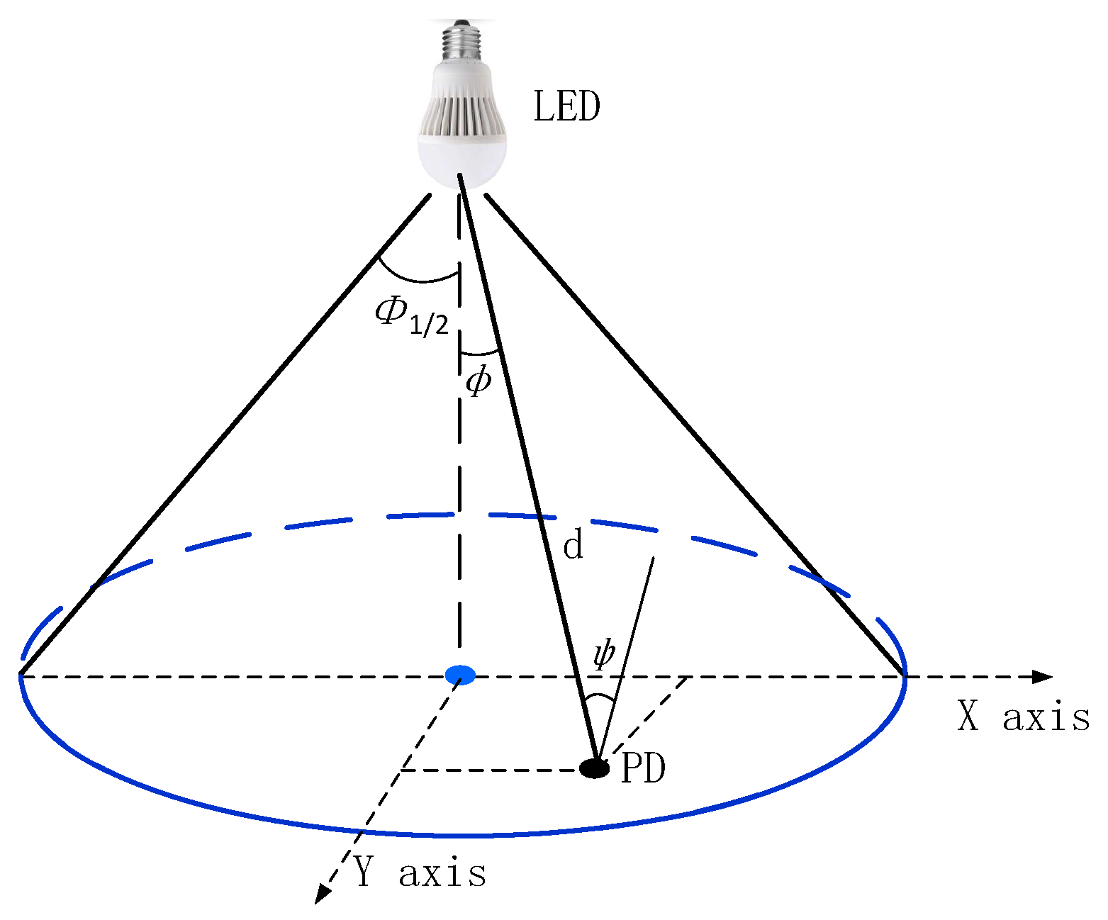
In this section, we first introduce the system model of the proposed scheme. For simplification, intensity modulation and direct detection (IM/DD) can be applied in the VLC system, where the message is carried by the light intensity emitted from the LED. In general, LEDs can be modeled as Lambertian emitters, and the line of sight (LOS) path is considered for the indoor VLC system where reflected light is much weaker then direct light [13]. At the receiver side, we assume perfect symbol synchronization. After the optical channel, the signal detected by the receiver can be expressed as:
where denotes the transmitted optical signal and can be considered as additive white Gaussian noise (AWGN) with variance . H represents the optical channel gain in VLC links, which is given as [1]:
As shown in Figure 1, m denotes the order of the Lambertian emission, defined as . is the receiver responsivity. denotes the effective receiver area of the receiver, and D is the distance between the transceivers. and are the angle of irradiance and incidence from the LED to the Photodetector (PD), respectively. is the gain of the optical filter, and is the gain of the optical concentrator. denotes the field of view (FOV) of the receiver.
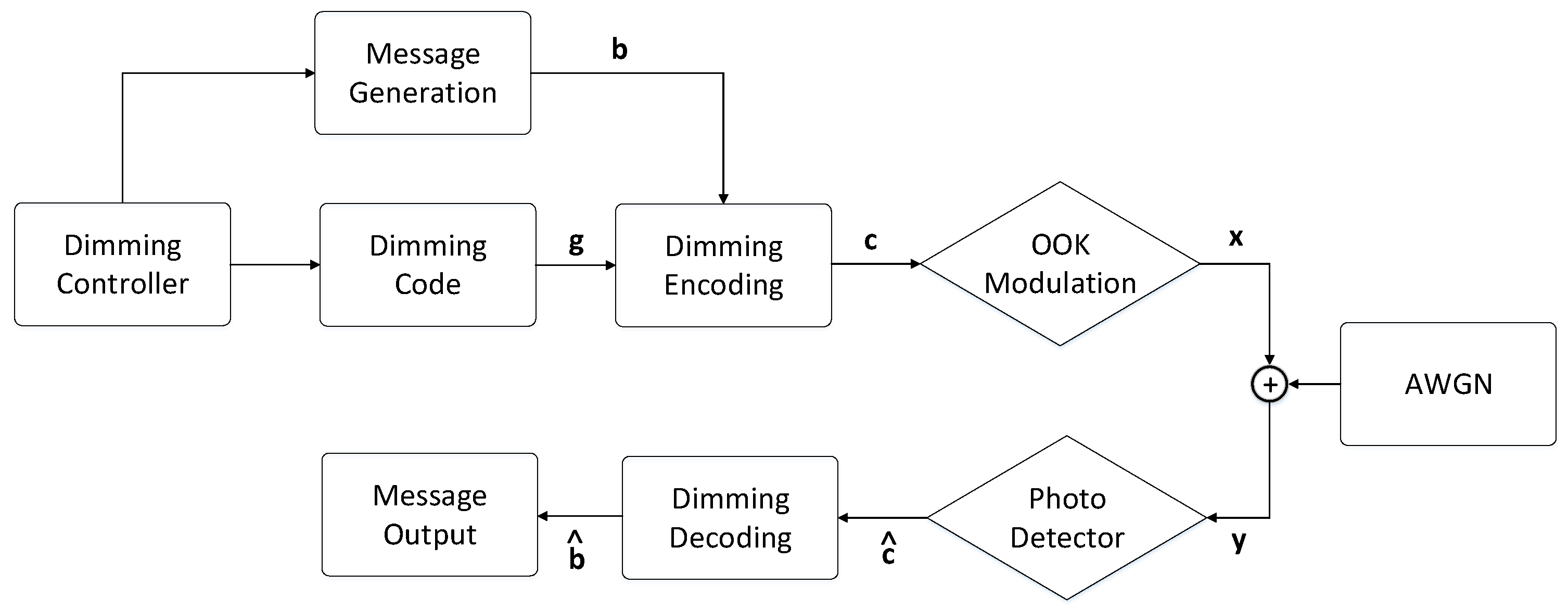
Unlike RF systems, the transmitted optical signal should meet the practical lighting constraints, which should be restricted to be nonnegative and less than the maximum limit of light intensity. Without loss of generality, we make the peak light intensity . Meanwhile, considering the dimming function, the average light intensity of the transmitted optical signal is defined as , with dimming level . For reference, the whole process of the proposed dimming scheme is shown in Figure 2.
Dimming controller: According to the dimming level , the “dimming controller” puts parameter K into the “message generation” part and the “dimming code” part, generating block code and dimming code , respectively.
Dimming encoding: With the input block code and dimming code, the “dimming encoding” makes the two parts a bitwise AND operation to generate the transmitted codewords satisfying the dimming requirement.
3. The Proposed Coding Scheme
In VLC links, the brightness can be determined by the average light intensity of the signal. We can achieve dimming control by adjusting the average intensity of the optical signal by constructing the transmitted codeword set. In this section, we will demonstrate the process of the encoding and decoding structure and give the algorithms accordingly.
3.1. Dimming Encoder
In this subsection, the encoding structure is given. To make our presentation clear, some notations are given as follows:
- (1)
- For a binary data sequence where the occurrence ratio of the bits of one and two is the same, based on the required dimming level, we first divide it into a certain number of blocks with binary data length K, denoted as , which is taken as the input of the “dimming encoding” part.
- (2)
- The dimming code is denoted as , where with , which corresponds to the specific dimming level. The normalized code weight of dimming code is:
- (3)
- We perform the bitwise AND operation on block code and each subsection of dimming code to generate new codeword . Then, we combine each to make the transmitted data , which satisfies the dimming requirement. For any random input data sequence, the ratio of bits of zeroes and ones is the same. Namely, these block codes are transmitted with equal probability. Therefore, the dimming level can be expressed as:
Therefore, the key point of the problem is the construction of the dimming code. To better distinguish the generation of codewords, we provide the following principles to construct the dimming code .
Principle 1.
The construction of the dimming code.
- (1)
- The dimming code corresponding to the minimum dimming level should guarantee thatwhenandwhen.
- (2)
- As mentioned above, the dimming factor can be changed proportionally with the code weight of the dimming code. To increase the dimming level, we can successively increase the number of “ON” levels of each. Therefore, the dimming resolution is.
- (3)
- The dimming code withis the same as thepart, and accordingly, the generated data are, where.
Example 1.
From the above analysis, the transmission efficiency can be expressed as:
where the transmission rate can be fixed under different dimming levels when the bandwidth is given. We conclude the performance comparison under different K where the corresponding dimming level and dimming range are determined, as shown in Table 3. The analysis shows that we can obtain a wider dimming range and more precise dimming levels with the increase of parameter K. However, a large value of K may degrade the performance of transmission efficiency. Thus, we can choose the proper dimming scheme depending on the specific transmission condition.
Consequently, we can summarize the above-mentioned encoding process as Algorithm 1 where ⨂ denotes the operation of bitwise AND.
| Algorithm 1 Dimming Encoding |
| Require: dimming factor input data bit and dimming code Ensure: if , where else , where |
3.2. Dimming Decoder
In this subsection, we will demonstrate the process of decoding the structure. To make our presentation clear, some notations are given as follows:
- (1)
- After maximum likelihood (ML) detection, the received binary data can be regarded as the estimation of transmitted data, which is denoted as , where with . Then, the binary data sequence is taken as the input of the “dimming decoding” part.
- (2)
- We perform the bitwise OR operation on each subsection of received binary codeword to estimate the original input data string .
Consequently, we can summarize the above-mentioned encoding process as Algorithm 2 where ⨁ denotes the operation of bitwise OR.
| Algorithm 2 Dimming Decoding |
| Require: received binary data Ensure: if else , where |
By means of the above-mentioned encoding/decoding algorithms, we can simultaneously achieve dimming control and data transmission with a fixed transmission rate.
4. Simulation Results
To evaluate the performance of the proposed encoding and decoding scheme, simulations have been carried out. The indoor environment was designed based on [1] with a room size of 5 m × 5 m × 3 m. The LED was installed at a height of 2.5 m from the floor, and the PD was put on the desk at 0.85 m under the LED. The semi-angle at half-power of the LED chip was 60 deg, and the field of view was 60 deg. The effective detected area of the receiver PD was . The gains of the optical filter and the refractive index of an optical concentrator were set as 1.0 and 1.5, respectively.
Next, to compare the error performance of the various dimming schemes, we fixed the the peak light intensity of transmitted signal P for a fair comparison according to the literature [11,14]. The signal-to-noise ratio (SNR) can be defined as SNR , where the code rate can be regarded as transmission efficiency here, and is the variance of the AWGN. The bit error rate (BER) was calculated by the Monte Carlo method, and the length of the transmitted data was set to be in the simulations. Simulations of BER have been carried out for the proposed dimming scheme with the different dimming levels where the SNR gain (in dB) was utilized, and three representative dimming levels (i.e., 0.25, 0.375, and 0.5) with different parameter K values were considered to examine the performance of the proposed scheme.
As shown in Figure 3, the red lines and blue lines represent the proposed scheme with parameter values and respectively. As the parameter K increased, the code rate decreased accordingly. We can see that the BER performance with outperformed under the same dimming levels. In terms of the same parameter , the error performance with dimming level was better than dimming levels and , 1.7 dB and 2.7 dB SNR gains at BER , respectively.
5. Conclusions
In this paper, we have proposed a block coding-based scheme to achieve dimming control, as well as data transmission with constant transmission efficiency, where a large dimming range can be achieved. Meanwhile, the encoding/decoding algorithm was provided accordingly. Via the bitwise AND operation on the block code and each subsection of dimming code to construct the proper codewords satisfying the dimming requirement, the proposed scheme is simple to implement and can maintain constant transmission efficiency under different dimming levels. Simulation results show that the proposed scheme can achieve reliable data transmission via the designed encoding/decoding structure. Therefore, it proves an attractive alternative dimming scheme.
Author Contributions
All authors contributed equally to writing the paper. Formal analysis, Y.Z.; funding acquisition, J.Z.; writing, original draft, Y.Z.; writing, review and editing, J.Z.
Funding
This work is supported in part by Grant No. 161100210200 from the Major Scientific and Technological of Henan Province, China.
Acknowledgments
The authors wish to thank the anonymous reviewers for their valuable suggestions.
Conflicts of Interest
The authors declare no conflict of interest.
References
- Komine, T.; Nakagawa, M. Fundamental analysis for visible light communication system using LED lights. IEEE Trans. Consum. Electron. 2004, 50, 100–107. [Google Scholar] [CrossRef]
- Vucic, J.; Kottke, C.; Nerreter, S.; Langer, K.D.; Walewski, J.W. 513 mbit/s visible light communications link based on dmt-modulation of a white LED. IEEE J. Lightw. Technol. 2010, 28, 3512–3518. [Google Scholar] [CrossRef]
- Karunatilaka, D.; Zafar, F.; Kalavally, V.; Parthiban, R. Led based indoor visible light communications: State of the art. IEEE Commun. Surv. Tutor. 2015, 17, 1649–1678. [Google Scholar] [CrossRef]
- Jovicic, A.; Li, J.; Richardson, T. Visible light communication: Opportunities, challenges and the path to market. IEEE Commun. Mag. 2013, 51, 26–32. [Google Scholar] [CrossRef]
- Randel, S.; Breyer, F.; Lee, S.C.J.; Walewski, J.W. Advanced modulation schemes for short-range optical communications. IEEE J. Sel. Top. Quant. 2010, 16, 1280–1289. [Google Scholar] [CrossRef]
- Zafar, F.; Karunatilaka, D.; Parthiban, R. Dimming schemes for visible light communication: The state of research. IEEE Wirel. Commun. 2015, 22, 29–35. [Google Scholar] [CrossRef]
- Rajagopal, S.; Roberts, R.D.; Lim, S.K. IEEE 802.15.7 visible light communication: Modulation schemes and dimming support. IEEE Commun. Mag. 2012, 50, 72–82. [Google Scholar] [CrossRef]
- Lee, K.; Park, H. Modulations for visible light communications with dimming control. IEEE Photonics Technol. Lett. 2011, 23, 1136–1138. [Google Scholar] [CrossRef]
- Sang, H.L.; Jung, S.Y.; Kwon, J.K. Modulation and coding for dimmable visible light communication. IEEE Commun. Mag. 2015, 53, 136–143. [Google Scholar] [CrossRef]
- Kim, J.; Park, H. A coding scheme for visible light communication with wide dimming range. IEEE Photonics Technol. Lett. 2014, 26, 465–468. [Google Scholar] [CrossRef]
- Kim, S.; Jung, S.Y. Novel FEC coding scheme for dimmable visible light communication based on the modified reedmuller codes. IEEE Photonics Technol. Lett. 2011, 23, 1514–1516. [Google Scholar] [CrossRef]
- Sang, H.L.; Ahn, K.I.; Kwon, J.K. Multilevel transmission in dimmable visible light communication systems. IEEE J. Lightw. Technol. 2013, 31, 3267–3276. [Google Scholar] [CrossRef]
- Lee, K.; Park, H.; Barry, J.R. Indoor channel characteristics for visible light communications. IEEE Commun. Lett. 2011, 15, 217–219. [Google Scholar] [CrossRef]
- Zuo, Y.; Zhang, J.; Zhang, Y.Y.; Chen, R.H. Weight threshold check coding for dimmable indoor visible light communication systems. IEEE Photonics J. 2018, 10, 1–11. [Google Scholar] [CrossRef]
Figure 1.
Optical channel model.

Figure 2.
Block diagram of the proposed scheme. OOK, on-off keying.

Figure 3.
Error performance of the proposed scheme under different dimming factor.


Table 1.
The dimming code under different dimming levels with .
| 100 | 010 | 001 | |
| 110 | 010 | 001 | |
| 111 | 010 | 001 | |
| 111 | 110 | 001 | |
| 111 | 111 | 001 | |
| 111 | 111 | 101 | |
| 111 | 111 | 111 |
Table 2.
The construction of generated codewords under dimming factor with .
| i | b | c | |||
|---|---|---|---|---|---|
| 1 | 000 | 100 | 010 | 001 | 000000000 |
| 2 | 001 | 100 | 010 | 001 | 000000001 |
| 3 | 010 | 100 | 010 | 001 | 000010000 |
| 4 | 100 | 100 | 010 | 001 | 100000000 |
| 5 | 011 | 100 | 010 | 001 | 000010001 |
| 6 | 101 | 100 | 010 | 001 | 100000001 |
| 7 | 110 | 100 | 010 | 001 | 100010000 |
| 8 | 111 | 100 | 010 | 001 | 100010001 |
Table 3.
The performance comparison under different K.
| K | ||||
|---|---|---|---|---|
| 2 | ||||
| 3 | ||||
| 4 | ||||
| K |
© 2019 by the authors. Licensee MDPI, Basel, Switzerland. This article is an open access article distributed under the terms and conditions of the Creative Commons Attribution (CC BY) license (http://creativecommons.org/licenses/by/4.0/).
Share and Cite
MDPI and ACS Style
Zuo, Y.; Zhang, J. A Novel Coding Based Dimming Scheme with Constant Transmission Efficiency in VLC Systems. Appl. Sci. 2019, 9, 803. https://doi.org/10.3390/app9040803
AMA Style
Zuo Y, Zhang J. A Novel Coding Based Dimming Scheme with Constant Transmission Efficiency in VLC Systems. Applied Sciences. 2019; 9(4):803. https://doi.org/10.3390/app9040803
Chicago/Turabian StyleZuo, Yu, and Jian Zhang. 2019. "A Novel Coding Based Dimming Scheme with Constant Transmission Efficiency in VLC Systems" Applied Sciences 9, no. 4: 803. https://doi.org/10.3390/app9040803
Note that from the first issue of 2016, this journal uses article numbers instead of page numbers. See further details here.