An Improved Analysis Method for Organic Rankine Cycles Based on Radial-Inflow Turbine Efficiency Prediction


Key Lab of Condition Monitoring and Control for Power Plant Equipment, North China Electric Power University, Ministry of Education, Baoding 071003, China
*
Author to whom correspondence should be addressed.
Appl. Sci. 2019, 9(1), 49; https://doi.org/10.3390/app9010049
Submission received: 21 November 2018
/
Revised: 15 December 2018
/
Accepted: 18 December 2018
/
Published: 24 December 2018
(This article belongs to the Special Issue Organic Rankine Cycle Systems for Waste-Heat Recovery)
Abstract
:The organic Rankine cycle (ORC) has been demonstrated to be an effective method for converting low-grade heat energy into electricity. This paper proposes an improved analysis method for the ORC system. A coupling model of the ORC system with a radial-inflow turbine efficiency prediction model is presented. Multi-objective optimization was conducted for a constant turbine efficiency ORC system (ORCCTE) and a predicted turbine efficiency ORC system (ORCDTE), and the optimization results were compared. Additionally, a sensitivity analysis was conducted with respect to the heat source temperature and the ambient temperature. It can be found that the predicted turbine efficiency decreases with the increasing evaporation temperature, and increases with the increasing condensation temperature. The turbine efficiency is not constant and it varies with operating conditions. The distribution of the Pareto frontier for ORCCTE system and ORCCTE system is different. Compared with the ORCCTE system, the ORCDTE system has a lower optimal evaporation temperature, but a higher optimal condensation temperature. The deviation between the predicted turbine efficiency and the constant turbine efficiency increases with the increasing heat source temperature but decreases with the increasing ambient temperature. Thus, the difference in the theoretical analysis results between ORCCTE system and ORCDTE system increases with the increasing heat source temperature but decreases with the increasing ambient temperature.
1. Introduction
Currently, energy shortage and environmental pollution are becoming increasingly prominent. There is a large amount of low-grade heat energy, which accounts for more than 50% of the total energy produced worldwide [1,2,3,4]. Considerable studies have been conducted regarding the recovery of low-grade heat energy. Organic Rankine Cycle (ORC) has exhibited high potential in terms of the utilization of low-grade heat energy conversion to electricity [5,6].
In the past few years, many studies have been conducted in the ORC research fields, mainly focusing on working fluid selection, system design optimization, and expander technologies [7,8,9]. Uusitalo et al. [10] investigated the impacts of working fluid type and critical properties on ORC system design and concluded that fluorocarbons and low critical temperature hydrocarbons are more suitable for low-temperature ORC applications, while siloxanes and high critical temperature hydrocarbons are more suitable for high–temperature ORC applications. Özahi et al. [11] conducted a thermodynamic and thermoeconomic study of an ORC system. Multi-objective optimization of the cycle was carried out with four working fluids, and they found that toluene is the best working fluid, producing 9.76% additional power for the solid waste power plant. Yang et al. [12] established a multi-objective optimization model of an ORC system for maximizing net power output and minimizing total investment cost, and the model was solved using a genetic algorithm with six working fluids. R245fa, whose optimized evaporation pressure is in the range of 1.1 Mpa–2.1 Mpa and optimized condensation temperature almost keeps a constant value of 298.15 K, is considered as the optimal working fluid. Yi et al. [13] proposed a thermo-economic-environmental optimization model integrating environmental impact and thermo-economic performance. A case study with R134a as the working fluid was conducted, and the results showed that a trade-off between the environmental objective and the thermo-economic objective can be achieved via multi-objective optimization. Behzadi et al. [14] conducted energy, exergy, and exergoeconomic analyses of an ORC unit that was coupled with a waste-to-heat plant, and found that R123 achieved the best performance for the integrated system. Gimelli et al. [15] established a multi-objective optimization model of an ORC system with electric efficiency and the overall area of the heat exchangers as objective functions; in the Pareto optimal front, electric efficiency is in the range of 14.1–18.9% and the overall area of the heat exchangers rangers from 446 m2 to 1079 m2.
Radial-inflow turbine is one of the key components of the ORC system, and its efficiency affects the system performance directly [16,17,18]. In most of the ORC theoretical analysis studies, radial-inflow turbine efficiency is assumed to be a constant value for different working fluids and operating conditions, which may lead to errors in theoretical results including working fluid selection and system parameter optimization. Rahbar et al. [19] proposed an optimized method for the ORC system based on the radial-inflow turbine, and constant expander efficiency was replaced with predicted expander efficiency. They found that there is a considerable difference in turbine efficiency for different operating conditions. Bahadormanesh et al. [20] combined the ORC thermodynamic model with a radial-inflow turbine design procedure. The firefly algorithm was used to optimize the thermal efficiency and the size parameter. Dong et al. [21] proposed an optimized coupling model of an ORC system with a radial-inflow turbine and investigated the impact of heat source outlet temperature on turbine efficiency and system performance.
There are very limited investigations that focus on the influence of turbine efficiency selection on the thermodynamic and economic performance of the ORC system simultaneously. Therefore, a radial-inflow turbine efficiency prediction model, which was coupled with an ORC thermodynamic model, was presented. In this study, benzene was selected as the working fluid, and multi-objective optimization algorithm was used to investigate the influence of turbine efficiency selection on the thermodynamic and economic performance of the ORC system. The ORCCTE system and ORCDTE system are compared in terms of the optimization results. In addition, a sensitivity analysis was conducted considering the fact that the heat source temperature and the ambient temperature are variable in practical application.
2. Materials and Methods
In this section, the thermodynamic and economic model of the ORC system are established, and the radial-inflow turbine efficiency prediction model is also presented. Then the objective functions and decision variables are selected to develop a multi-objective optimization model for the ORC system.
2.1. Thermodynamic Model
To compare the performance of ORCCTE system and ORCDTE system conveniently, a basic ORC system is studied in this paper. Figure 1 shows the diagram of a basic ORC system, which consists of four main components: Evaporator, turbine, condenser, and pump. The corresponding temperature-entropy (T-s) diagram of the basic ORC system, which is usually used to illustrate the thermal process, is shown in Figure 2.
The thermal process of the basic ORC system (Figure 2) is described as follows.
Process 5–0: The heat transferred from the waste flue gas to the organic working fluid in the evaporator is expressed by:
Process 0–2: The power generation of the turbine is given by:
Process 2–4: The heat rejected by the working fluid in the condenser can be calculated by:
Process 4–5: The power consumption of the pump is given by:
The net power output produced by the ORC system is defined by:
The thermal efficiency of the ORC system is determined by:
2.2. Economic Model
The total capital cost of the ORC system is mainly determined from the cost of the four components (evaporator, turbine, condenser, and pump). The bare module equipment cost (US dollars in the year 1996) of each component can be calculated by:
where Cb is the basic cost of each equipment. Z is the related parameters of each ORC component; for evaporator and condenser, it refers to heat transfer area; for the pump, it means the power consumption; for the turbine, it refers the power generation. Fbm, B1, B2, K1, K2, K3, C1, C2, C3 are the constants for different ORC components [22]. Fm and Fp represent the material factors and pressure factor for different components.
The total capital cost of the ORC system is the sum of the cost of each component, which can be expressed as:
Considering the value of money at different periods, the total capital cost of the ORC system is adjusted by using a chemical engineering plant cost index (CEPCI):
where CEPCI1996 and CEPCI2014 are the chemical engineering plant cost index in 1996 and 2014 respectively.
The specific invest cost (SIC) is the system total cost of per unit net power output:
2.3. Radial-Inflow Turbine Efficiency Prediction Model
Basically, for the ORC system within the power range of 50–5000 kW, an axial turbine and a radial-inflow turbine are proposed as two options [23]. The radial-inflow turbine presents an excellent aerodynamic performance, as it can deal with large enthalpy drops with relatively low peripheral speeds, has higher single-stage expansion ratio, and good off-design performance [19,20,21]. In this paper, the heat source inlet temperature is at a relatively high level (523.15 K), the radial-inflow turbine was selected as the expander to deal with the high expansion ratio. A radial-inflow turbine efficiency prediction model is employed to calculate a more accurate turbine efficiency. Figure 3 shows the working fluid flow process in the radial-inflow turbine. State 0 represents the initial state of the working fluid at the radial-inflow turbine inlet (nozzle inlet), state 1 represents the state of the working fluid at the nozzle outlet or the rotor inlet, and state 2 represents the state at the rotor outlet. In the nozzle, the organic vapor from the evaporator expands and accelerates (from state 0 to state 1), with enthalpy dropping. Subsequently, the working fluid continues to expand and the kinetic energy and dropping enthalpy are converted into the mechanical energy of the rotor (form state 1 to state 2). Figure 4 shows the velocity triangle of the radial-inflow turbine, which is used to express the velocity distribution at the rotor inlet and outlet.
The peripheral efficiency of the radial-inflow turbine can be expressed as [23]:
According to reference [24], the velocity ratio and the degree of reaction Ω have a greater impact on the peripheral efficiency, and the Lagrange multiplier method is used to optimize both parameters:
where m is an intermediate variable and can be expressed as:
The efficiency of the radial-inflow turbine is defined as the ratio of the actual enthalpy drop ∆h to the isentropic enthalpy drop ∆hs [24]:
Five kinds of turbine loss are considered in the radial-inflow turbine efficiency prediction model, including nozzle passage loss, rotor passage loss, leaving velocity loss, friction loss, and leakage loss. The estimation of these losses is listed as follows:
Nozzle passage loss coefficient:
Rotor passage loss coefficient:
Leaving velocity loss coefficient:
Friction loss coefficient:
Leakage loss coefficient:
Thus, radial-inflow turbine efficiency can be expressed as:
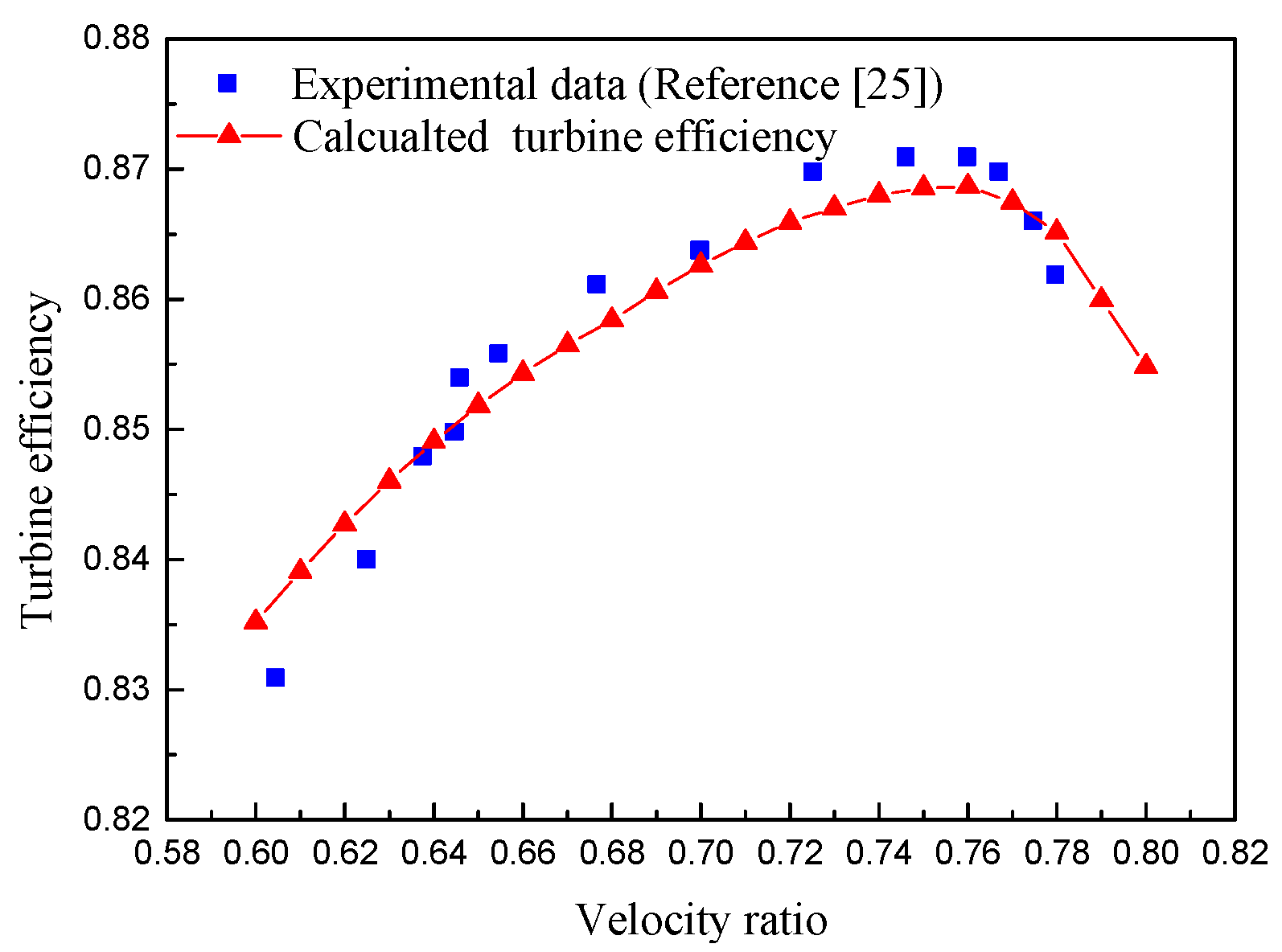
The turbine efficiency prediction model is validated by comparison of the calculated value of turbine efficiency with the experimental data in Reference [25], as shown in Figure 5. It can be found that the calculated value of turbine efficiency is in good agreement with the experimental data in Reference.
2.4. Multi-Objective Optimization Model
In this paper, multi-objective grey wolf optimizer (MOGWO) algorithm is employed for optimizing the ORC system. Some standard unconstrained, constrained, and engineering design problems have been used to validate MOGWO [26]. The results are compared with other multi-objective algorithms including Multi-objective Particle Swarm Optimization (MOPSO), Multi-objective Evolutionary Algorithm Based on Decomposition (MOEA/D), non-dominated sorting genetic algorithm II (NSGA-II), and Strength Pareto Evolutionary Algorithm 2 (SPEA2) to evaluate the efficiency and effectiveness of MOGWO [26,27,28,29,30]. The comparison results show that the MOGWO can provide very competitive optimization results. And in terms of convergence, spread and coverage MOGWO presents excellent performance. MOGWO is developed on the basis of grey wolf optimizer (GWO). Two components including an archive which is used to store the non-dominated Pareto optimization solutions and a leader selection mechanism that is used to select α, β, and δ wolves from the archive are integrated with GWO to perform multi-objective optimization, which is called MOGWO. The grey wolf optimizer (GWO) is inspired by the grey wolves, including their social leadership and hunting mechanism. The flowchart of MOGWO is shown in Figure 6. First, initialize the grey wolves population including the number and position of the grey wolves, maximum iteration and the archive size. Calculate the fitness of each grey wolf according to their position, sort the non-dominated solutions and initialize the Prato archive through saving the non-dominated solutions to it. Select the fittest, second and third fittest solutions (the wolves that gain the best, second and third best positions) as α, β, and δ wolves by leader selection mechanism. Update the positions of the current wolves according to the positions of α, β, and δ wolves and the distance between the current wolves and α, β, and δ wolves to generate new wolves (solutions). Calculate the fitness of the updated grey wolves and find new non-dominated solutions. Save new non-dominated solutions in the Prato archive and remove the dominated solutions simultaneously. If the Prato archive is full, remove some of the archive members based on crowding distance to meet the archive size. Then conduct non-dominated sorting for the Prato archive members and update the leaders (α, β, and δ wolves). If the termination condition (maximum iteration number) is satisfied, report the optimal Pareto solutions and the MOGWO ends.
To compare the ORCCTE system and ORCDTE system, the thermal efficiency and specific investment cost are selected as the thermodynamic and economic objectives respectively. Two parameters including evaporation temperature and condensation temperature are selected as independent variables for optimization of the ORC system. The mathematical model of the multi-objective optimization for the ORC system can be described as follows:
The logical bounds of the decision variables can be described as follows:
3. Results and Discussion
In this paper, a small ORC system is developed (150 kW is considered the reference size). The low-grade flue gas is selected as the heat source, and the heat source inlet temperature and outlet temperature are 523.15 K and 363.15 K, respectively. The ambient temperature and ambient pressures are 293.15 K and 1.01 MPa, respectively. The cooling water at the ambient temperature is taken as a heat sink, thus the inlet temperature of cooling water is assumed to be 293.15 K. The objective of this paper is to compare the difference between the ORCCTE system and the ORCDTE system. Therefore, only one working fluid (benzene) is selected in this paper. Benzene is a dry working fluid that is suitable for medium-high temperature heat source. Its critical temperature and critical pressures are 562.05 K and 4.894 Mpa, respectively. The constant turbine efficiency employed in this paper is assumed to be 0.7 [31], and the pump isentropic efficiency is assumed to be 0.7.
3.1. Comparison of the ORCCTE System and ORCDTE System
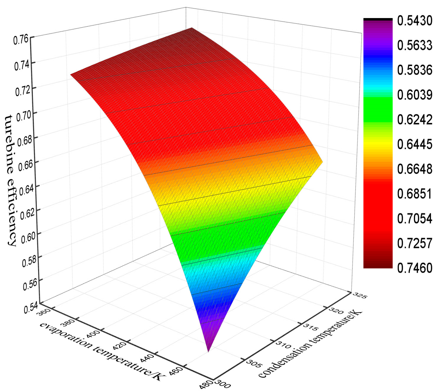
The radial-inflow turbine efficiency is obtained based on the prediction model in Section 2.3. Figure 7 shows the variation of the turbine efficiency with evaporation and condensation temperature. It is evident that turbine efficiency decreases with the increasing evaporation temperature, and increases with the increasing condensation temperature. It can be concluded that turbine efficiency increases with the decreasing pressure ratio. The maximum turbine efficiency is 0.746, and the minimum is 0.543, the relative difference reaches 27.21%. The maximum difference between the constant turbine efficiency and the predicted turbine efficiency reaches 0.157, and the relative error is 22.43%. From the above data, it can be found that turbine efficiency is not constant, and will vary with operating parameters. Therefore, it is necessary to couple the ORC system with the radial-inflow turbine efficiency prediction model.
Multi-objective optimization is conducted for the ORCCTE system and the ORCDTE system with respect to thermodynamic and economic performance. The multi-objective optimization Pareto frontier of both ORC systems is shown in Figure 8. It is apparent that there is a significant difference in the distribution of the Pareto frontier between the ORCCTE system and the ORCDTE system. Compared with the ORCCTE system, the thermal efficiency of the ORCDTE system lies at a lower level, and the specific investment cost of the ORCDTE system is distributed over a wider range. Figure 8 also shows the turbine efficiency value corresponding to the Pareto frontier of the ORCDTE. The turbine efficiency value is less than the constant turbine efficiency (0.7), and the lower turbine efficiency value leads to lower net power output. Thus, the thermal efficiency of the ORCDTE system is less than that of the ORCCTE system, and the specific investment cost of the ORCDTE system is higher than that of the ORCCTE system. It can also be found that the deviation of the distribution of the Pareto frontier between the ORCCTE system and the ORCDTE system increases with the decreasing turbine efficiency.
It should be noted that each point on the Pareto frontier is a potential solution for the multi-objective optimization. There is not an optimal point to maximize the thermal efficiency and minimize the specific investment cost simultaneously. Therefore, it is necessary to conduct a decision-making process based on engineering experience. The aid of ideal point method is used to conduct the process of decision-making in this paper [32]. Taking the Pareto frontier of ORCCTE system as an example, the decision-making process using the aid of ideal point method is presented in Figure 8. The ideal point has the highest thermal efficiency and the lowest specific investment cost simultaneously but this point does not actually exist. The point on the Pareto frontier that has the shortest distance from the ideal point is selected as the final optimal solution. The final optimal solutions for the ORCCTE system and the ORCDTE system are listed in Table 1. Compared with the ORCCTE system, the ORCDTE system has a lower optimal evaporation temperature but a higher evaporation temperature. Due to the low turbine efficiency, the ORCDTE system has lower thermal efficiency and a higher specific investment cost. Therefore, the assumption of constant turbine efficiency in the ORC system would lead to errors in the determination of the optimal operating evaporation temperature and condensation temperature. Therefore, adopting predicted turbine efficiency in the ORC system optimization is necessary, and can enhance the reliability and accuracy of the analysis results.
Figure 9 and Figure 10 present the distribution of the optimal evaporation temperature and condensation temperature for the ORCCTE system and the ORCDTE system. As mentioned, the ORCCTE system has lower thermal efficiency and a higher specific investment cost than ORCDTE system, as shown in Figure 9 and Figure 10. The optimal evaporation temperature for the ORCDTE system is distributed over a wider range than the ORCCTE system, as shown in Figure 9. For ORCDTE system the optimal evaporation temperature is distributed in the range of 393–412 K; while for ORCCTE system the optimal evaporation temperature is distributed in the range of 397–412 K. As shown in Figure 10, the condensation temperature for the ORCDTE system is distributed in a slightly wider range than the ORCCTE system. For ORCCTE system, most of the condensation temperature is distributed in the range of 303.15–307.5 K; while for ORCDTE system, the condensation temperature is distributed in the range of 303.15–308.5 K. It can be found that the impact of turbine efficiency selection on the evaporation temperature is greater than that on the condensation temperature.
3.2. Sensitivity Analysis and Comparison of the ORCCTE System and the ORCDTE System
The heat source temperature and ambient temperature are not constant in practical engineering application. Therefore, in this section, sensitivity analysis with regard to heat source temperature and the ambient temperature is conducted for both ORC systems. Multi-objective optimization is carried out at each operating condition, and the final optimal solution at each operating condition is selected using the aid of ideal point method.
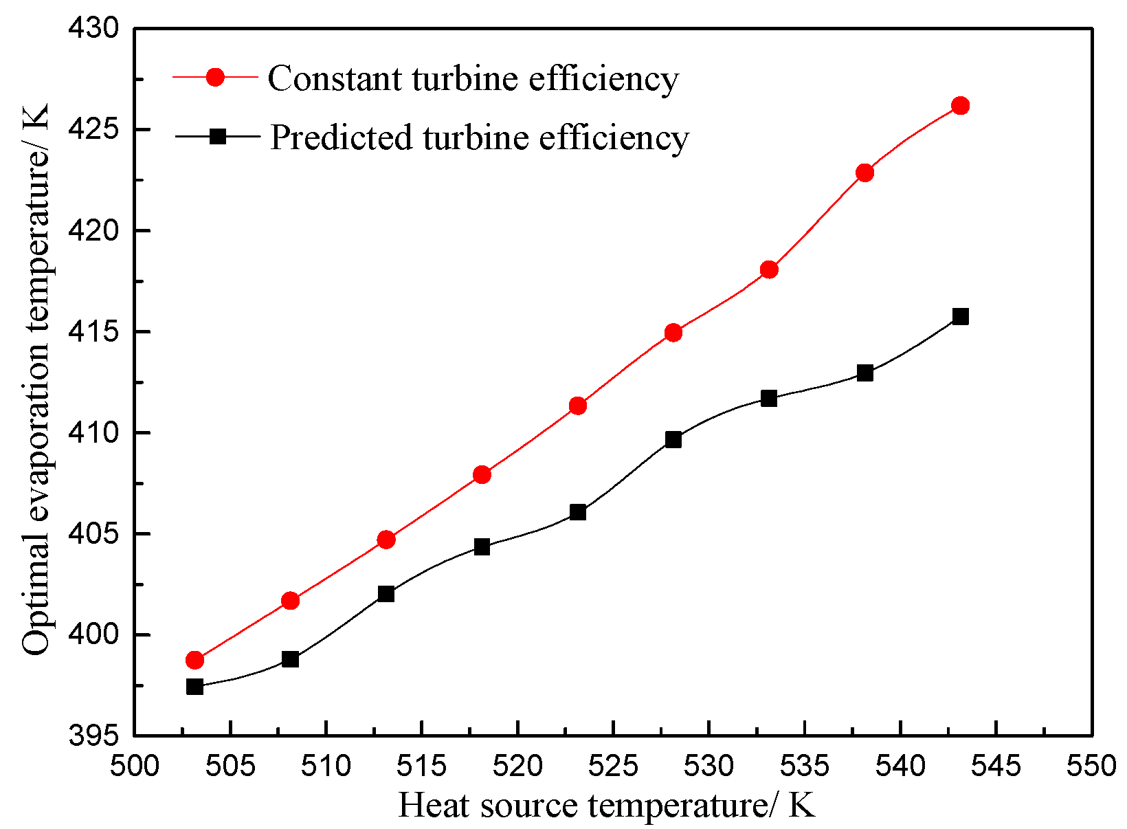
Figure 11 shows the variation of the optimal evaporation temperature with the increasing heat source temperature. With the increasing heat source temperature, the optimal evaporation temperature increases. Additionally, the optimal evaporation temperature for ORCCTE system increases faster. The optimal evaporation temperature for the ORCCTE system is higher than that for the ORCDTE system, and the difference between the two ORC systems becomes larger with the increasing evaporation temperature, the maximum difference is 10.44 K. Figure 12 shows the variation of the optimal condensation temperature with the increasing heat source temperature. With the increasing heat source temperature, the optimal condensation temperature increases slightly. The optimal condensation temperature for the ORCDTE system is higher than that for the ORCCTE system. It also can be found that the optimal condensation temperature for the ORCCTE system varies in the range of 305.5–306.5 K, while for ORCDTE system, the optimal condensation temperature varies in the range of 306.5–308.5 K, which is slightly wider. Compared with the optimal condensation temperature, it can be found that the variation range of the optimal evaporation temperature is much wider, which indicates that the influence of heat source temperature on optimal evaporation temperature is greater than that on optimal condensation temperature.
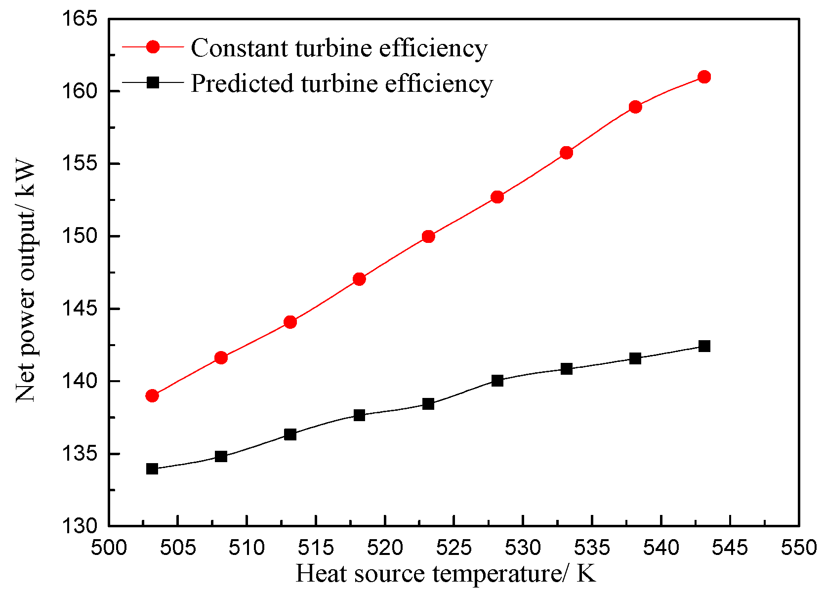
Figure 13 shows the variation of turbine efficiency with the increasing heat source temperature. Turbine efficiency decreases with the increasing heat source temperature. The reason is that with the increasing heat source temperature, the optimal evaporation temperature increases faster than the optimal condensation temperature, which leads to the increases in pressure ratio. Thus, turbine efficiency decreases. The variation of the net power output at different heat source temperature is presented in Figure 14. For both ORCCTE system and ORCDTE system, the net power output increases with the increasing heat source temperature. However, the increasing rate of the net power output of ORCCTE system is higher than that of ORCDTE system. The reason is that for ORCDTE system, decreasing turbine efficiency decreases the increasing rate of net power output. Additionally, the net power output of ORCCTE system is always higher than that of ORCDTE system, and the difference of net power output between the two ORC system becomes larger the increasing heat source temperature, the maximum relative deviation is 11.54%.
Figure 15 and Figure 16 show the optimal evaporation temperature and the optimal condensation temperature at different ambient temperatures, respectively.
Figure 15 shows the variation of the optimal evaporation temperature with the increasing ambient temperature. The optimal evaporation temperature for the ORCDTE system increases with the increasing ambient temperature, while the optimal evaporation temperature for the ORCCTE system stays at approximately 411 K, which indicates that the ambient temperature has almost no effect on the optimal evaporation temperature for ORCCTE system. Additionally, the optimal evaporation temperature for ORCCTE system is higher than that for ORCDTE system, and the difference decreases gradually with the increasing ambient temperature. Figure 16 shows the variation of the optimal condensation temperature with the increasing ambient temperature. The optimal condensation temperature linearly increases with the increment of ambient temperature. In addition, the optimal condensation temperature for the ORCDTE system is always higher than that for the ORCCTE system, and the difference value stays at approximately 2 K. From Figure 15 and Figure 16, it can also be found that the influence of ambient temperature on the optimal condensation temperature is greater than that on the optimal evaporation temperature.
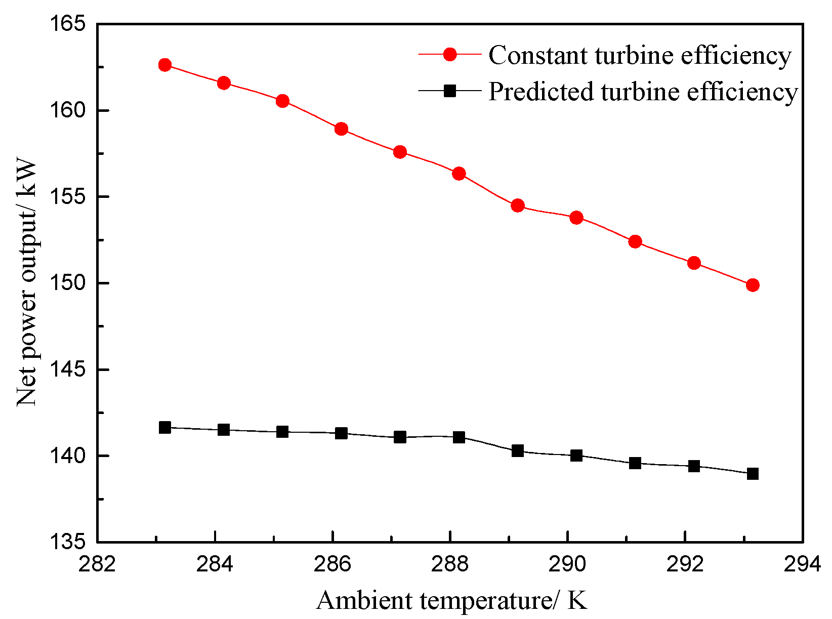
Figure 17 shows the variation of turbine efficiency with the increasing ambient temperature. With the increasing ambient temperature, turbine efficiency almost increases monotonically. From Figure 15 and Figure 16, it can be found that the increasing rate of optimal condensation temperature is greater than that of optimal condensation temperature. Thus the pressure ratio decreases and the turbine efficiency increases accordingly. Figure 18 shows the net power output at different ambient temperatures. The net power output of both ORC systems decreases with the increment of ambient temperature. Moreover, the decreasing rate of the net power output for ORCCTE is higher than that of the ORCDTE system. The net power output of the ORCDTE system only decreased by 2.68 kW over the investigated ambient temperature. The reason is that the amount of the decrement of net power output reduces due to the increasing turbine efficiency. It can also be found that the net power output of the ORCCTE is higher than that of the ORCDTE system, and the difference shrinks with the increasing ambient temperature.
In conclusion, with the increasing heat source temperature, the deviation between the predicted turbine efficiency and the constant turbine efficiency increases. Thus, the error in the theoretical analysis results (including optimal operating parameter determination and performance indicator calculation) caused by assuming the constant turbine efficiency, becomes larger. However, with the increasing ambient temperature, the deviation between the predicted turbine efficiency and the constant turbine efficiency gradually decreases. As a result, the error in the theoretical analysis results caused by assuming the constant turbine efficiency decreases.
4. Conclusions
In this paper, an improved analysis method for the ORC system is proposed. To study the influence of turbine efficiency selection on the ORC system, a radial-inflow turbine efficiency prediction model is coupled with the ORC system. Multi-objective optimization was conducted for the ORCCTE system and the ORCDTE system, and the optimization results were compared. In addition, a sensitivity analysis was conducted with respect to heat source temperature and ambient temperature. The following conclusions can be obtained:
- (1)
- Turbine efficiency is not constant, it decreases with the increasing evaporation temperature, and increases with the increasing condensation temperature. For radial-inflow turbine with organic working fluid benzene, the largest difference between the predicted turbine efficiency and the constant turbine efficiency is 0.157 for the given operating conditions.
- (2)
- The distribution of the Pareto frontier for the ORCCTE system and the ORCDTE system are different. Compared with the ORCCTE system, the ORCDTE system has a lower optimal evaporation temperature but a slightly higher optimal condensation temperature.
- (3)
- As the heat source temperature increases, the deviation between the predicted turbine efficiency and constant turbine efficiency increases, and the error in the theoretical analysis results caused by assuming a constant turbine efficiency in ORC system increases. Meanwhile, with the increasing ambient temperature, the deviation between the predicted turbine efficiency and the constant turbine efficiency decreases, and the error in the theoretical analysis results caused by assuming a constant turbine efficiency decrease.
Author Contributions
All authors contributed to this work. P.L. is the main author of this work. Z.H. guided the analysis and the writing of the paper. X.J. and Z.M. assisted with the modeling. X.H. and Z.W. provided suggestions with respect to article modification.
Funding
This research was funded by the National Natural Science Foundation of China (Grant No. 51306059) and Fundamental Research Funds for the Central Universities (Grant No. 2017XS120).
Conflicts of Interest
The authors declare no conflict of interest.
Nomenclature
| c | absolute velocity, m s−1 |
| C | capital cost, $ |
| D | diameter, m |
| ratio of wheel diameter | |
| f | coefficient for friction loss |
| h | specific enthalpy, kJ kg−1 |
| l | blade height, m |
| m | mass flow rate, kg s−1 |
| P | pressure, MPa |
| Q | heat transfer rate, kW |
| T | Temperature, K |
| U | peripheral velocity, m s−1 |
| v | specific volume, m3 kg−1 |
| w | relative velocity, m s−1 |
| W | power, kW |
Greek Letters
| η | efficiency |
| velocity ratio | |
| ξ | loss coefficient |
| φ | stator blade velocity coefficient |
| ψ | rotor blade velocity coefficient |
| α | absolute flow angle |
| β | relative flow angle |
| Ω | degree of reaction |
| Δh | entropy drop, kJ kg−1 |
| ΔTp | pinch point temperature difference, K |
| δ | tip clearance, m |
Subscripts
| 0, 1, 2, 2s, 4, 5s, 5 | state points |
| BM | bare module |
| con | condenser |
| critical | critical |
| eva | evaporator |
| f | working fluid |
| g1 | flue gas inlet |
| max | maximum |
| min | minimum |
| net | net |
| opt | optimal |
| pump | pump |
| s | isentropic |
| tur | turbine |
| the | thermal |
| u | peripheral |
References
- Mahmoudi, A.; Fazli, M.; Morad, M.R. A recent review of waste heat recovery by Organic Rankine Cycle. Appl. Therm. Eng. 2018, 143, 660–675. [Google Scholar] [CrossRef]
- Fu, H.; Li, Z.; Liu, Z.; Wang, Z. Research on big data digging of hot topics about recycled water use on micro-blog based on particle swarm optimization. Sustainability 2018, 10, 2488. [Google Scholar] [CrossRef]
- Li, P.; Han, Z.; Jia, X.; Mei, Z.; Han, X.; Wang, Z. Analysis and comparison on thermodynamic and economic performances of an organic Rankine cycle with constant and one-dimensional dynamic turbine efficiency. Energy Convers. Manag. 2019, 180, 665–679. [Google Scholar] [CrossRef]
- Song, J.; Feng, Q.; Wang, X.; Fu, H.; Jiang, W.; Chen, B. Spatial Association and Effect Evaluation of CO2 Emission in the Chengdu-Chongqing Urban Agglomeration: Quantitative Evidence from Social Network Analysis. Sustainability 2019, 11, 1. [Google Scholar] [CrossRef]
- Chen, L.X.; Hu, P.; Zhao, P.P.; Xie, M.N.; Wang, F.X. Thermodynamic analysis of a High Temperature Pumped Thermal Electricity Storage (HT-PTES) integrated with a parallel organic Rankine cycle (ORC). Energy Convers. Manag. 2018, 177, 150–160. [Google Scholar] [CrossRef]
- Mahmoudzadeh Andwari, A.; Pesiridis, A.; Karvountzis-Kontakiotis, A.; Esfahanian, V. Hybrid electric vehicle performance with organic Rankine cycle waste heat recovery system. Appl. Sci. 2017, 7, 437. [Google Scholar] [CrossRef]
- Landelle, A.; Tauveron, N.; Haberschill, P.; Revellin, R.; Colasson, S. Organic Rankine cycle design and performance comparison based on experimental database. Appl. Energy 2017, 204, 1172–1187. [Google Scholar] [CrossRef]
- Feng, Y.; Zhang, Y.; Li, B.; Yang, J.; Shi, Y. Comparison between regenerative organic Rankine cycle (RORC) and basic organic Rankine cycle (BORC) based on thermoeconomic multi-objective optimization considering exergy efficiency and levelized energy cost (LEC). Energy Convers. Manag. 2015, 96, 58–71. [Google Scholar] [CrossRef]
- Da Lio, L.; Manente, G.; Lazzaretto, A. A mean-line model to predict the design efficiency of radial inflow turbines in organic Rankine cycle (ORC) systems. Appl. Energy 2017, 205, 187–209. [Google Scholar] [CrossRef]
- Uusitalo, A.; Honkatukia, J.; Turunen-Saaresti, T.; Grönman, A. Thermodynamic evaluation on the effect of working fluid type and fluids critical properties on design and performance of Organic Rankine Cycles. J. Clean. Prod. 2018, 188, 253–263. [Google Scholar] [CrossRef]
- Özahi, E.; Tozlu, A.; Abuşoğlu, A. Thermoeconomic multi-objective optimization of an organic Rankine cycle (ORC) adapted to an existing solid waste power plant. Energy Convers. Manag. 2018, 168, 308–319. [Google Scholar] [CrossRef]
- Yang, F.; Zhang, H.; Song, S.; Bei, C.; Wang, H. Thermoeconomic multi-objective optimization of an organic Rankine cycle for exhaust waste heat recovery of a diesel engine. Energy 2015, 93, 2208–2228. [Google Scholar] [CrossRef]
- Yi, Z.; Luo, X.; Yang, Z.; Wang, C.; Chen, J.; Chen, Y.; Ponce-Ortega, J.M. Thermo-economic-environmental optimization of a liquid separation condensation-based organic Rankine cycle driven by waste heat. J. Clean. Prod. 2018, 184, 198–210. [Google Scholar] [CrossRef]
- Behzadi, A.; Gholamian, E.; Houshfar, E.; Habibollahzade, A. Multi-objective optimization and exergoeconomic analysis of waste heat recovery from Tehran’s waste-to-energy plant integrated with an ORC unit. Energy 2018, 160, 1055–1068. [Google Scholar] [CrossRef]
- Gimelli, A.; Luongo, A.; Muccillo, M. Efficiency and cost optimization of a regenerative Organic Rankine Cycle power plant through the multi-objective approach. Appl. Therm. Eng. 2017, 114, 601–610. [Google Scholar] [CrossRef]
- Li, P.; Han, Z.; Jia, X.; Mei, Z.; Han, X. Analysis of the Effects of Blade Installation Angle and Blade Number on Radial-Inflow Turbine Stator Flow Performance. Energies 2018, 11, 2258. [Google Scholar] [CrossRef]
- Han, Z.; Fan, W.; Zhao, R. Improved thermodynamic design of organic radial-inflow turbine and ORC system thermal performance analysis. Energy Convers. Manag. 2017, 150, 259–268. [Google Scholar] [CrossRef]
- Alshammari, F.; Karvountzis-Kontakiotis, A.; Pesiridis, A.; Giannakakis, P. Off-design performance prediction of radial turbines operating with ideal and real working fluids. Energy Convers. Manag. 2018, 171, 1430–1439. [Google Scholar] [CrossRef]
- Rahbar, K.; Mahmoud, S.; Al-Dadah, R.K.; Moazami, N. Modelling and optimization of organic Rankine cycle based on a small-scale radial inflow turbine. Energy Convers. Manag. 2015, 91, 186–198. [Google Scholar] [CrossRef]
- Bahadormanesh, N.; Rahat, S.; Yarali, M. Constrained multi-objective optimization of radial expanders in organic Rankine cycles by firefly algorithm. Energy Convers. Manag. 2017, 148, 1179–1193. [Google Scholar] [CrossRef]
- Dong, B.; Xu, G.; Li, T.; Luo, X.; Quan, Y. Parametric analysis of organic rankine cycle based on a radial turbine for low-grade waste heat recovery. Appl. Therm. Eng. 2017, 126, 470–479. [Google Scholar] [CrossRef]
- Xiao, L.; Wu, S.Y.; Yi, T.T.; Liu, C.; Li, Y.R. Multi-objective optimization of evaporation and condensation temperatures for subcritical organic Rankine cycle. Energy 2015, 83, 723–733. [Google Scholar] [CrossRef]
- Fiaschi, D.; Manfrida, G.; Maraschiello, F. Thermo-fluid dynamics preliminary design of turbo-expanders for ORC cycles. Appl. Energy 2012, 97, 601–608. [Google Scholar] [CrossRef]
- Lee, Y.; Lu, G. Radial Inflow Turbine and Centrifugal Compressor; China Machine Press: Beijing, China, 1984. [Google Scholar]
- Jones, A.C. Design and Test of a Small, High Pressure Ratio Radial Turbine. J. Turbomach. 1996, 118, 362–370. [Google Scholar] [CrossRef]
- Jangir, P.; Jangir, N. A new Non-Dominated Sorting Grey Wolf Optimizer (NS-GWO) algorithm: Development and application to solve engineering designs and economic constrained emission dispatch problem with integration of wind power. Eng. Appl. Artif. Intell. 2018, 72, 449–467. [Google Scholar] [CrossRef]
- Kang, L.; Du, H.L.; Zhang, H.; Ma, W.L. Systematic research on the application of steel slag resources under the background of big data. Complexity 2018, 2018, 6703908. [Google Scholar] [CrossRef]
- Yang, A.M.; Yang, X.L.; Chang, J.C.; Bai, B.; Kong, F.B.; Ran, Q.B. Research on a fusion scheme of cellular network and wireless sensor networks for cyber physical social systems. IEEE Access 2018, 6, 18786–18794. [Google Scholar] [CrossRef]
- Lu, C.; Xiao, S.; Li, X.; Gao, L. An effective multi-objective discrete grey wolf optimizer for a real-world scheduling problem in welding production. Adv. Eng. Softw. 2016, 99, 161–176. [Google Scholar] [CrossRef]
- Wu, K.; Du, K.; Hu, G. A novel design concept for fabricating 3D graphene with the assistant of anti-solvent precipitated sulphates and its Li-ion storage properties. J. Mater. Chem. A 2018, 6, 3444–3453. [Google Scholar] [CrossRef]
- Imran, M.; Usman, M.; Park, B.S.; Kim, H.J.; Lee, D.H. Multi-objective optimization of evaporator of organic Rankine cycle (ORC) for low temperature geothermal heat source. Appl. Therm. Eng. 2015, 80, 1–9. [Google Scholar] [CrossRef]
- Feng, Y.; Zhang, Y.; Li, B.; Yang, J.; Shi, Y. Sensitivity analysis and thermoeconomic comparison of ORCs (organic Rankine cycles) for low temperature waste heat recovery. Energy 2015, 82, 664–677. [Google Scholar] [CrossRef]
Figure 1.
Schematic diagram of a basic organic Rankine cycle (ORC) system.
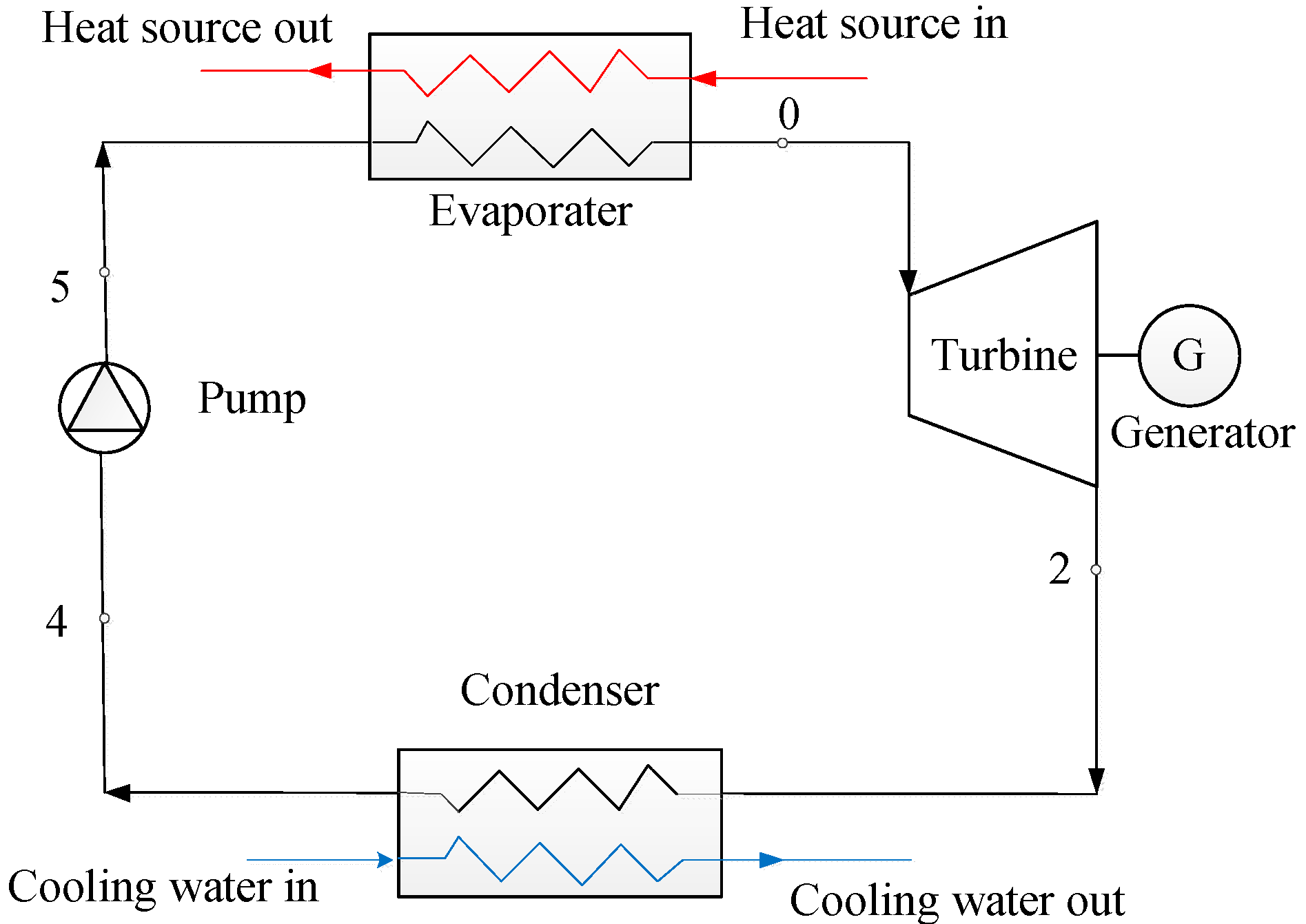
Figure 2.
Typical T-s diagram of a basic ORC system.
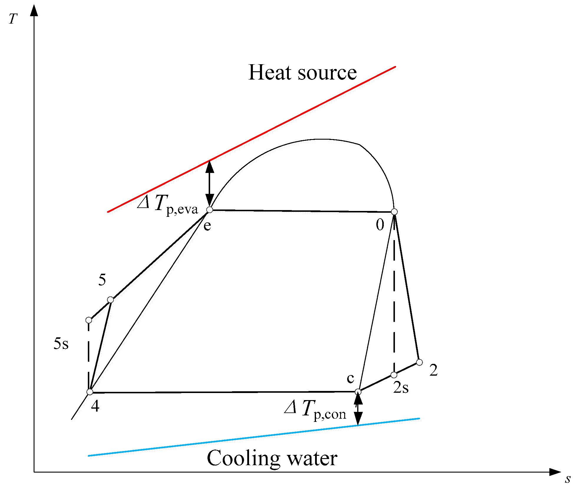
Figure 3.
Working fluid flow process in the radial-inflow turbine.
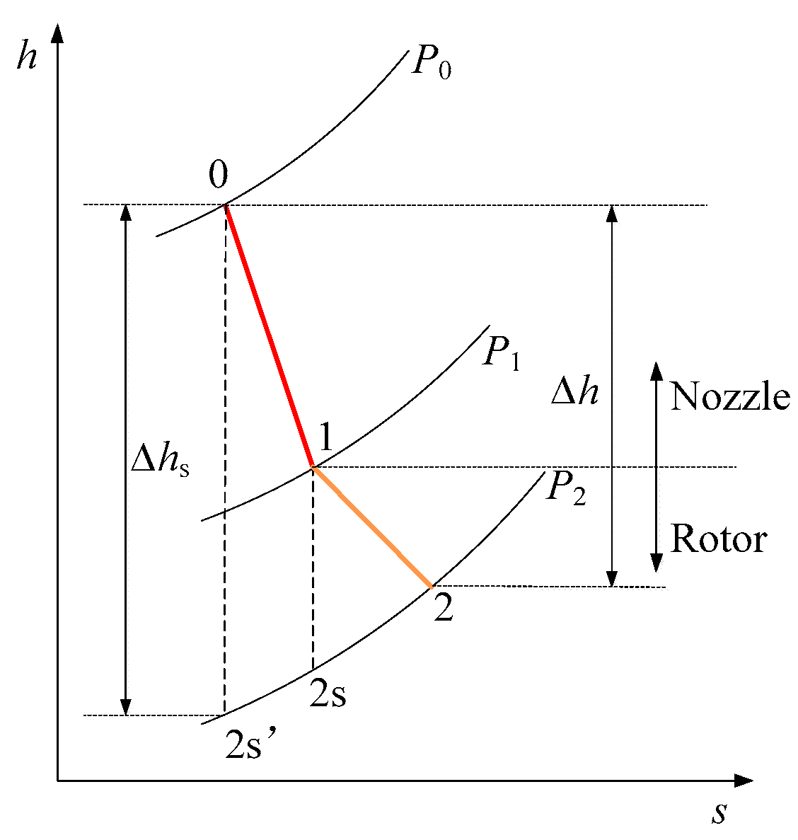
Figure 4.
Velocity triangle of the radial-flow turbine.
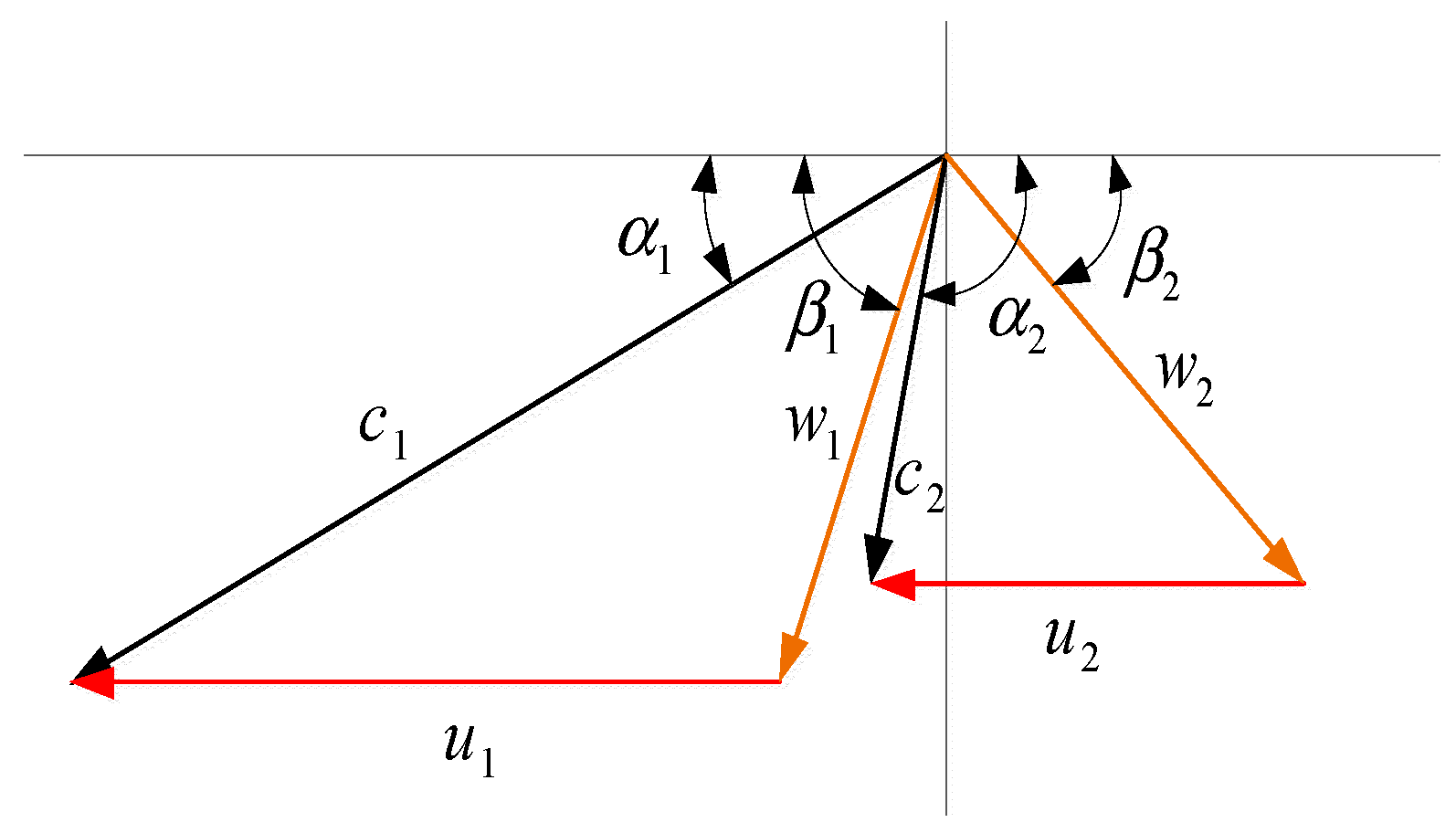
Figure 5.
Validation of the turbine efficiency prediction model.

Figure 6.
Flowchart of the multi-objective grey wolf optimizer (MOGWO) algorithm.
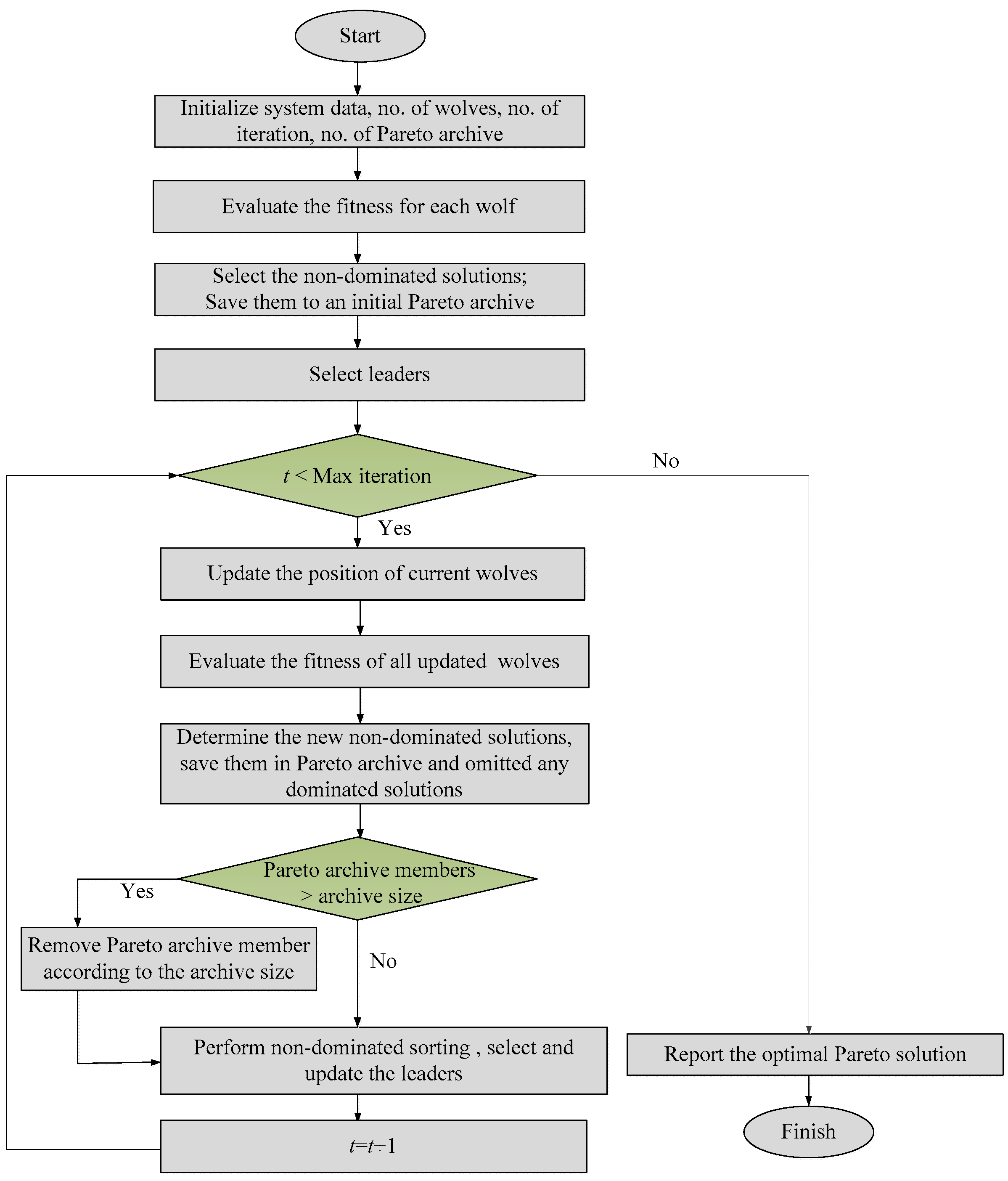
Figure 7.
Radial-inflow turbine efficiency at different evaporation and condensation temperature.

Figure 8.
Pareto frontier of ORCCTE system and ORCDTE system.
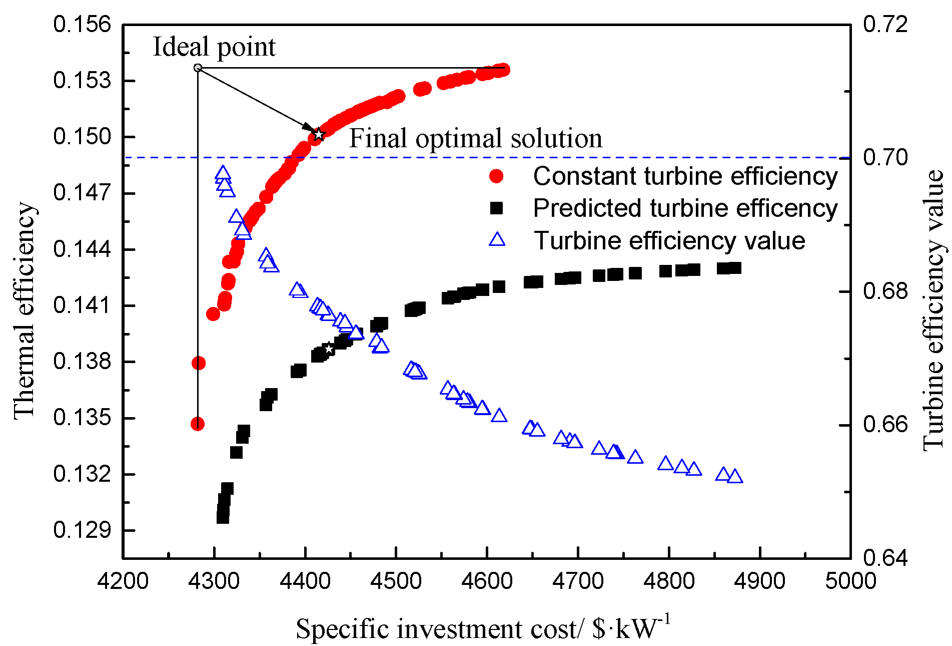
Figure 9.
Distribution of optimal evaporation temperature.

Figure 10.
Distribution of optimal condensation temperature.
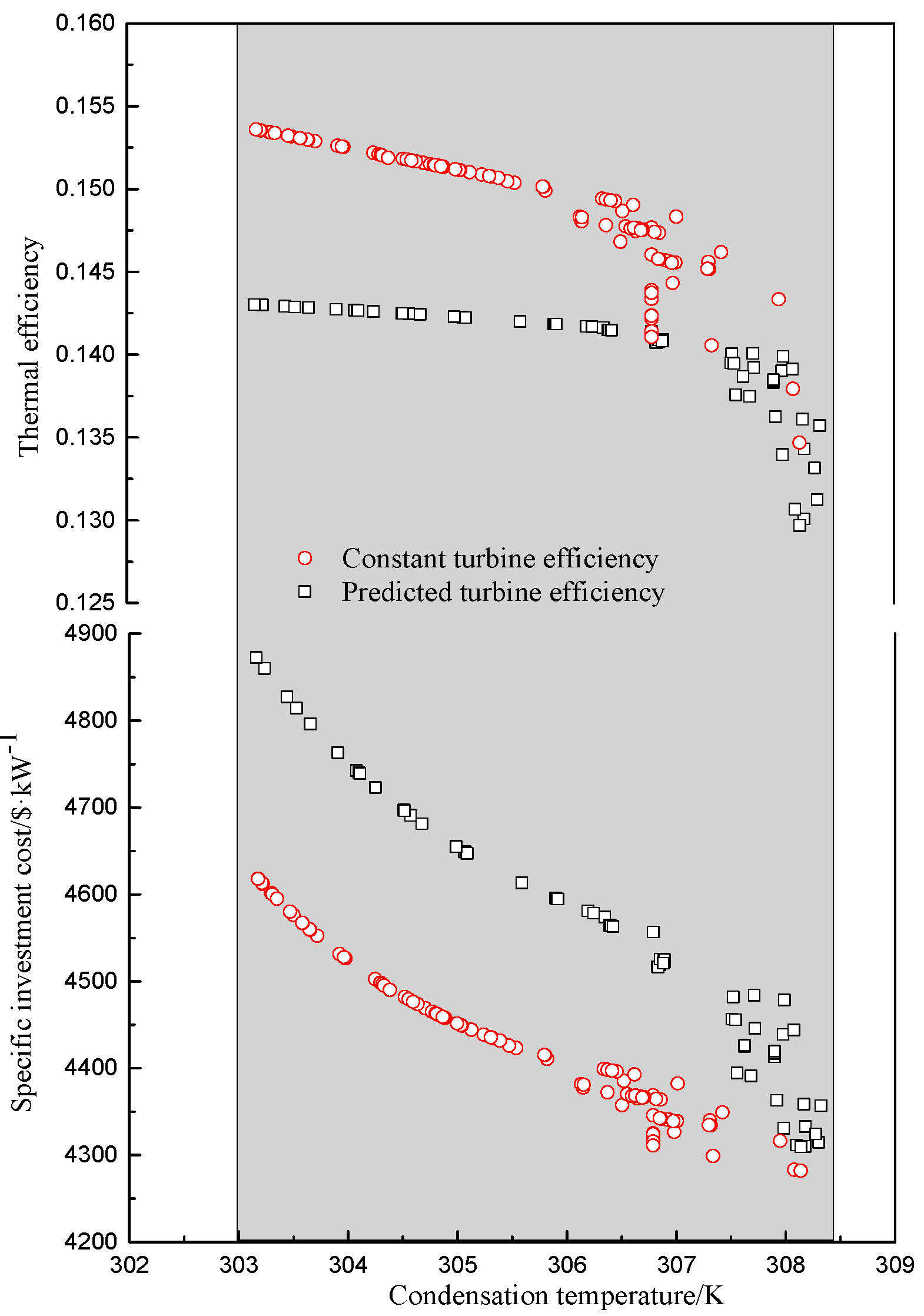
Figure 11.
Optimal evaporation temperature at different heat source temperature.

Figure 12.
Optimal condensation temperature at different heat source temperature.
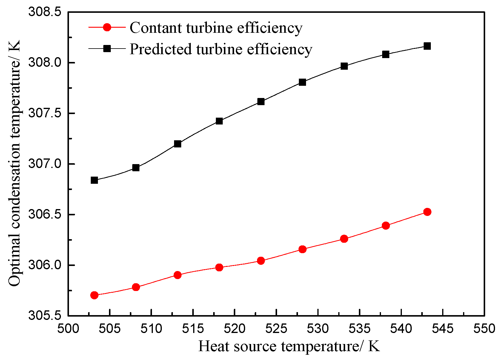
Figure 13.
Turbine efficiency at different heat source temperature.
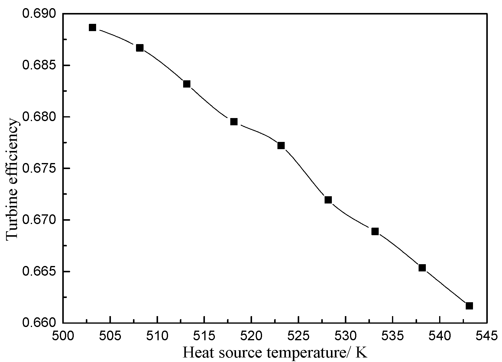
Figure 14.
Net power output at different heat source temperature.

Figure 15.
Optimal evaporation temperature at different ambient temperature.
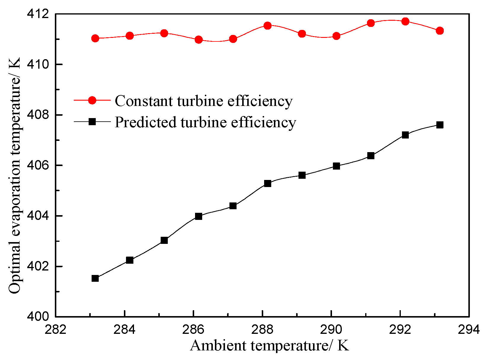
Figure 16.
Optimal condensation temperature at different ambient temperature.
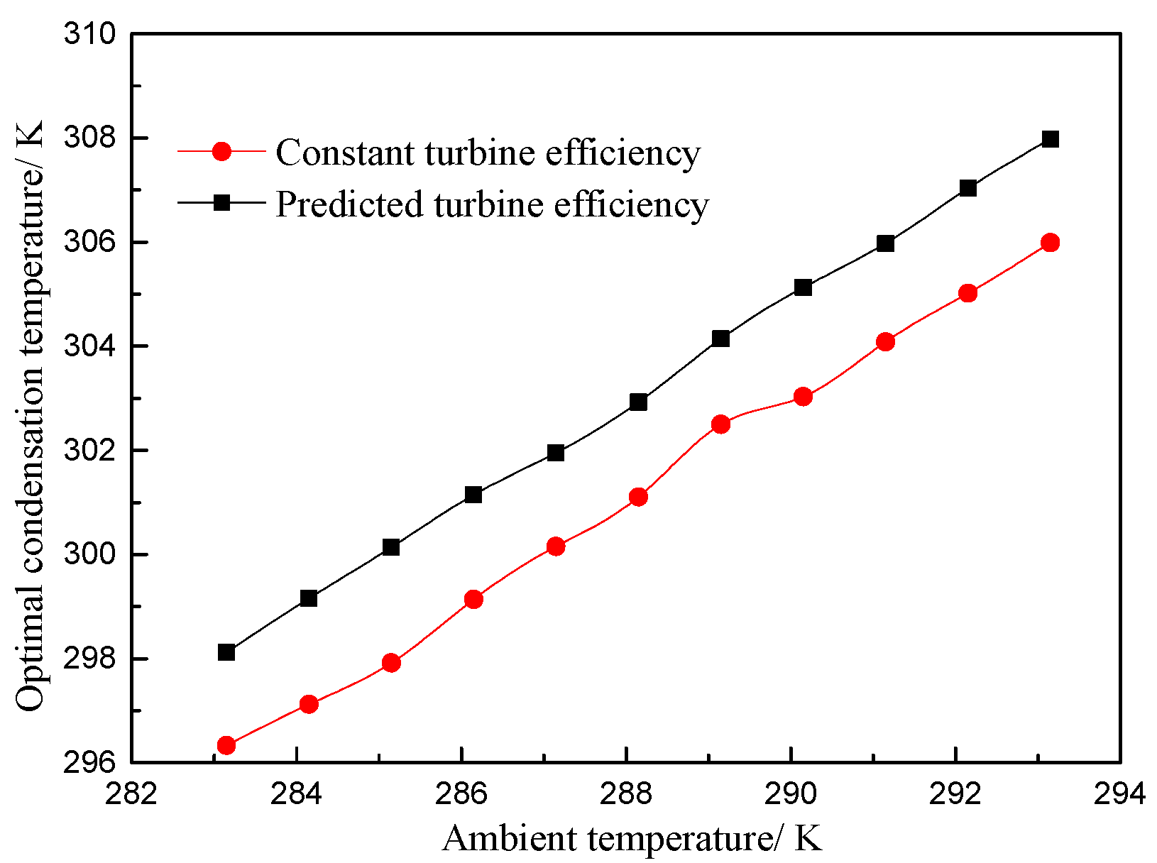
Figure 17.
Turbine efficiency at different ambient temperature.
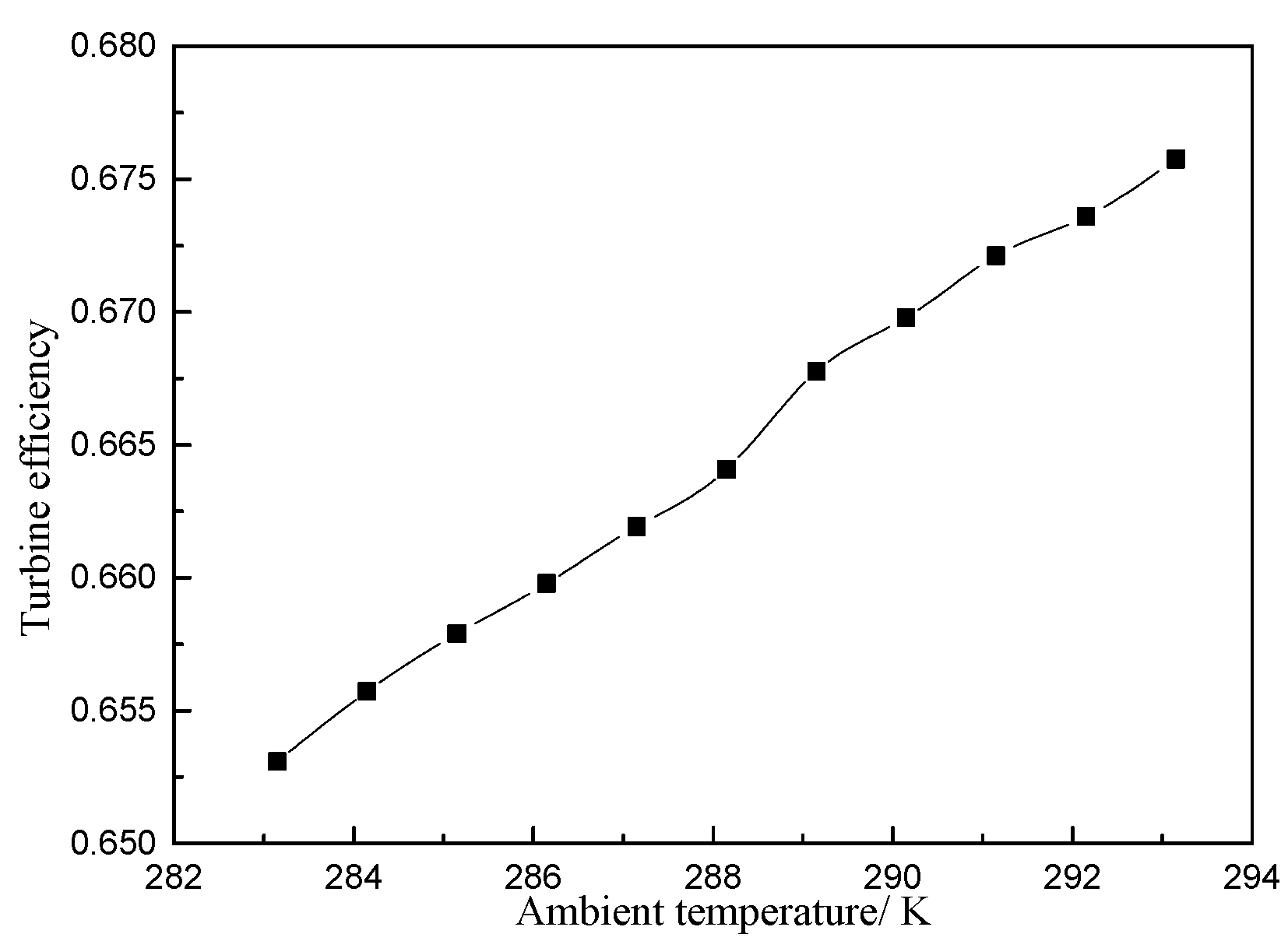
Figure 18.
Net power output at different ambient temperature.

Table 1.
Final optimal solution for the ORC system with different types of turbine efficiency.
| Parameters | Constant Turbine Efficiency | Predicted Turbine Efficiency |
|---|---|---|
| Evaporation temperature/K | 411.33 | 406.06 |
| Condensation temperature/K | 306.04 | 307.62 |
| Thermal efficiency | 0.150 | 0.139 |
| Specific investment cost/$·kW−1 | 4415.14 | 4426.27 |
© 2018 by the authors. Licensee MDPI, Basel, Switzerland. This article is an open access article distributed under the terms and conditions of the Creative Commons Attribution (CC BY) license (http://creativecommons.org/licenses/by/4.0/).
Share and Cite
MDPI and ACS Style
Li, P.; Han, Z.; Jia, X.; Mei, Z.; Han, X.; Wang, Z. An Improved Analysis Method for Organic Rankine Cycles Based on Radial-Inflow Turbine Efficiency Prediction. Appl. Sci. 2019, 9, 49. https://doi.org/10.3390/app9010049
AMA Style
Li P, Han Z, Jia X, Mei Z, Han X, Wang Z. An Improved Analysis Method for Organic Rankine Cycles Based on Radial-Inflow Turbine Efficiency Prediction. Applied Sciences. 2019; 9(1):49. https://doi.org/10.3390/app9010049
Chicago/Turabian StyleLi, Peng, Zhonghe Han, Xiaoqiang Jia, Zhongkai Mei, Xu Han, and Zhi Wang. 2019. "An Improved Analysis Method for Organic Rankine Cycles Based on Radial-Inflow Turbine Efficiency Prediction" Applied Sciences 9, no. 1: 49. https://doi.org/10.3390/app9010049
Note that from the first issue of 2016, this journal uses article numbers instead of page numbers. See further details here.