Article

Microstructures of Three In-Situ Reinforcements and the Effect on the Tensile Strengths of an Al-Si-Cu-Mg-Ni Alloy

Shaanxi Province Engineering Research Centre for Aluminium/Magnesium Light Alloy and Composites, Materials and Chemical Engineering School, Xi’an Technological University, Xi’an 710021, China
*
Authors to whom correspondence should be addressed.
Appl. Sci. 2018, 8(9), 1523; https://doi.org/10.3390/app8091523
Submission received: 19 July 2018 / Revised: 24 August 2018 / Accepted: 27 August 2018 / Published: 1 September 2018
(This article belongs to the Special Issue Metal Matrix Composite)

Abstract

:
In the present paper, the microstructures of three kinds of in-situ reinforcements Al-Ti-C, Al-Ti-B, and Al-Ti-B-C-Ce were deeply investigated using a combination of scanning electron microscopy, X-ray diffraction spectroscopy, and transmission electron microscopy. The effect of in-situ reinforcements on the room temperature and elevated temperature (350 °C) tensile strengths of Al-13Si-4Cu-1Mg-2Ni alloy were analyzed. It is found that doping with trace amounts of B and Ce, the size of the Al3Ti phase in the in-situ reinforced alloy changed from 80 µm (un-reinforced) to about 10 µm, with the simultaneous formation of the AlTiCe phase. The Al-Ti-B-C-Ce reinforcement which is rapid solidified, was more effective and superior to enhance the tensile strengths of the Al-13Si-4Cu-1Mg-2Ni alloy, both at room and high temperatures than those of addition other reinforcements. The room temperature (RT) strength increased by 19.0%, and the 350 °C-strength increased by 18.4%.

1. Introduction

In last two decades, in situ metal matrix composites, as a branch of discontinuous reinforced metal matrix composites, have been attracting many researchers interest and have made notable achievements [1]. The word “in situ composite” comes from “in situ crystallization”. The concept of in-situ composite was proposed by Soviet scientist Merzhanov et al., where they synthesized TiB2 reinforced Cu based functional gradient materials by Self-Propagating High-temperature Synthesis in 1987 [2,3,4]. High quality in situ aluminum-matrix and titanium-matrix composites have been developed for various applications in vehicles, aerospace, and the machinery industries [5,6]. However, the research on in situ metal matrix composites and its current research investment, are far from meeting the urgent needs of the high-tech development of modern industry and the military [7,8]. Therefore, it is of great importance to conduct more in-depth research on in situ metal matrix composites, for applications in leading-edge manufacturing and innovation areas, such as alloy material design theory, amorphous nano-crystalline matrix inoculation and refinement mechanism, and ceramic nano-particulate reinforcement. The goal is to make major breakthroughs rapidly in nano-fabrication technology and basic theoretical research in new types of metal matrix composite materials, so as to contribute to the transformation and upgrade of the traditional metal material industry [9,10,11].
The advantages of aluminum-based composite materials include high specific strength, excellent corrosion resistance, and outstanding electrical conductivity [12]. The primary purpose of adding reinforcement to the aluminum matrix, is to compensate for the low strength, inferior high-temperature performance, and poor wear resistance of aluminum. For aluminum matrix composites, the most effective particulate reinforcements are mostly ceramic particles. These particles can be divided into two types, one is directly formed in the matrix and the other is added after artificial synthesis. In addition to the high specific strength and specific modulus, these reinforcements have superior high-temperature performance; they are therefore widely used in the production of composite materials [13,14].
Table 1 shows the property parameter of the compound, which can be used as a particle enhancer. In recent decades, studies on TiC, TiB2, ZrB2, AlN or its biphasic particle composite reinforced aluminum matrix composites have been increasing. TiC particles, as the reinforced phase of in-situ aluminum matrix composites, show many excellent properties: high hardness, high melting point, high elastic modulus, low thermal conductivity, and good wettability and thermodynamic stability in molten aluminum [15]. TiB2 has been intensively investigated in modern engineering materials, due to its high melting point, superior hardness, and excellent corrosion resistance, as well as good thermal and electrical conductivity. At present, TiB2 is widely applied in the field of high-temperature electrodes, armor, cutting tools, and other structural materials [16].
TiC and TiB2 are usually synthesized in situ by Al-Ti-C and Al-Ti-B systems. At present, the most commonly used reinforcements in the industry are Al-Ti-C and Al-Ti-B reinforcements [20,21]. Table 2 shows the characteristics of various reinforcements [22,23,24,25,26]. Researches have been fully developed and widely used in industrial production. However, Al-Ti-C as well Al-Ti-B, have some disadvantages in the application process, where Al-Ti-B contains TiB2 which tends to accumulate in molten aluminum, decreasing the refining effect. In addition, Al3Ti particulates contained in Al-Ti-C and Al-Ti-B refinements have low refinement efficiency and degrade the matrix properties because of its needle-like appearance. New Al-Ti-B-C-Ce reinforcement, enhance and inherited the merits of the traditional reinforced body, have the effect of refining grain size, and improved its shortcoming to further improve the refining effect, and thus have a great advantage in improving the materials mechanical performance [27].
Table 3 shows the tensile properties of different alloys in the reference literature, at room temperature.
Al-13Si-4Cu-1Mg-2Ni alloy, is a widely used piston aluminum alloy through the enhanced in-situ method which further improves its mechanical properties. This is of great significance in meeting the research and development needs of high performance engines, such as high-power density diesel engines. In this paper, the strengthening effect of these three kinds of enhancers, and the addition to the piston alloy by in-situ generation, is studied to provide guidance for the development of a new piston alloy.

2. Experimental

2.1. Intermediate Alloy Preparation

The powders needed to prepare the intermediate alloy were Ti, C, KBF4, K2TiF6, and B4C powder. The Al-13Si-5Cu-1Mg-2Ni matrix alloy was prepared using highly pure Al (99.95 wt. %), pure Mg (99.9 wt. %), pure Si (99.9 wt. %), Al-50 wt. % Cu, and Al-10 wt. % Ni master alloys. The matrix alloy preparation process also used Al-20 wt. % Ce, Al-P alterative, mischmetal rich in La and Ce, and Hexachloroethane. Table 4 are the powders used to prepare intermediate alloys.
For Al-Ti-C intermediate alloy, Ti powder and C powder in a Ti:C = 4:1 mass ratio and 10 wt. % were used. Al were measured according to the reaction formula:
Ti + C → TiC
Al + Ti → Al3Ti
Al + C → Al4C3
These powders were mixed uniformly in a mortar and poured into a stainless-steel briquette mold (Φ 35 mm × 10 mm). The powder was pressed to form a powder briquette. The briquette was dried and placed in molten pure aluminum liquid at 1000 °C, for an in-situ reaction to produce Al-3Ti-0.25C intermediate alloy.
For Al-Ti-B intermediate alloy, KBF4 and K2TiF6 were blended according to the reaction formula and stirred directly into 850 °C pure molten aluminum. The in-situ reaction then occurred in molten aluminum to produce the Al-Ti-B intermediate alloy.
K2TiF6 + 2KBF4 → TiB2 + 4KF + 5F2
2K2TiF6 + 2KBF4 + 5Al → TiAl3 + TiB2 + 6KF + 2AlF3 + 4F2
Al-Ti intermediate alloy was prepared by melting in a Model WK-II non-consumable vacuum electric arc furnace, according to a specific composition. B4C powder wrapped in aluminum foil at 800 °C, was placed in a melting crucible to prepare Al-Ti-B-C intermediate alloy. Al-Ti-B-C-Ce was then prepared by melting Al-Ti-B-C intermediate alloy and Al-20Ce alloy, in the WK-II non-consumable vacuum arc furnace. The prepared block of Al-Ti-B-C-Ce reinforcement was then placed in a Model LZK-12A vacuum quenching furnace, for rapid solidification.

2.2. Experimental Process

2.2.1. The Process of Matrix Alloy

In the experimental study, an alloy model of Al-13Si-4Cu-1Mg-2Ni (wt. %) was prepared in an intermediate frequency induction melting furnace. Firstly, pure aluminum ingot blocks were added into the graphite crucible and were melted, then the pieces of pure silicon Al-10 wt. %Ni and Al-50 wt. %Cu intermediate alloys were added into the melt, respectively. Furthermore, mischmetal, rich in elements La and Ce, together with Al-P alloy as the modifier agents, were added into the molten alloy. Hexachloroethane as the degassing agent was added at 720–740 °C, and held for 15 min. Then Mg block was added under the melt completely, to keep it from contacting oxygen and burning. The crucible was removed with a crucible clamp and the slags were removed with a stainless-steel spoon. After skimming off slag, it was poured into a metal mold to obtain Φ 20 mm × 100 mm cast rods.

2.2.2. The Process of Composite Alloys

When the matrix alloy was melted, three different reinforcements Al-Ti-C, Al-Ti-B, and Al-Ti-B-C-Ce (5 wt. %) briquette were added in an aluminum foil to the molten aluminum. Figure 1 shows the preparation technology of the composite alloy. After skimming off slag, it was poured into a metal mold to obtain Φ 20 mm × 100 mm cast rods.

2.2.3. The Microstructure Analysis

The composite materials alloy when solidified, was analyzed using a Quanta 400 F (FEI, Hillsboro, OR, USA) thermal field emission scanning electron microscope equipped with an INCA energy dispersive spectrometer and JEM-2010 transmission electron microscope (JEOL, Tokyo, Japan) in detail. The phase compositions contained in the alloy prepared were examined using an XRD-6000 X-ray diffract meter (Shimadzu, Kyoto, Japan).

2.2.4. The Mechanical Tensile Tests

The tensile strengths of the cast Al-13Si-4Cu-1Mg-2Ni alloy at 25 °C and 350 °C, were tested with the Instron 1195 mechanical testing machine (Instron, Shanghai, China).

3. Results and Discussion

3.1. Metallurgical Analysis of Al-3Ti-0.25C Intermediate Alloy

3.1.1. X-ray Diffraction Analysis
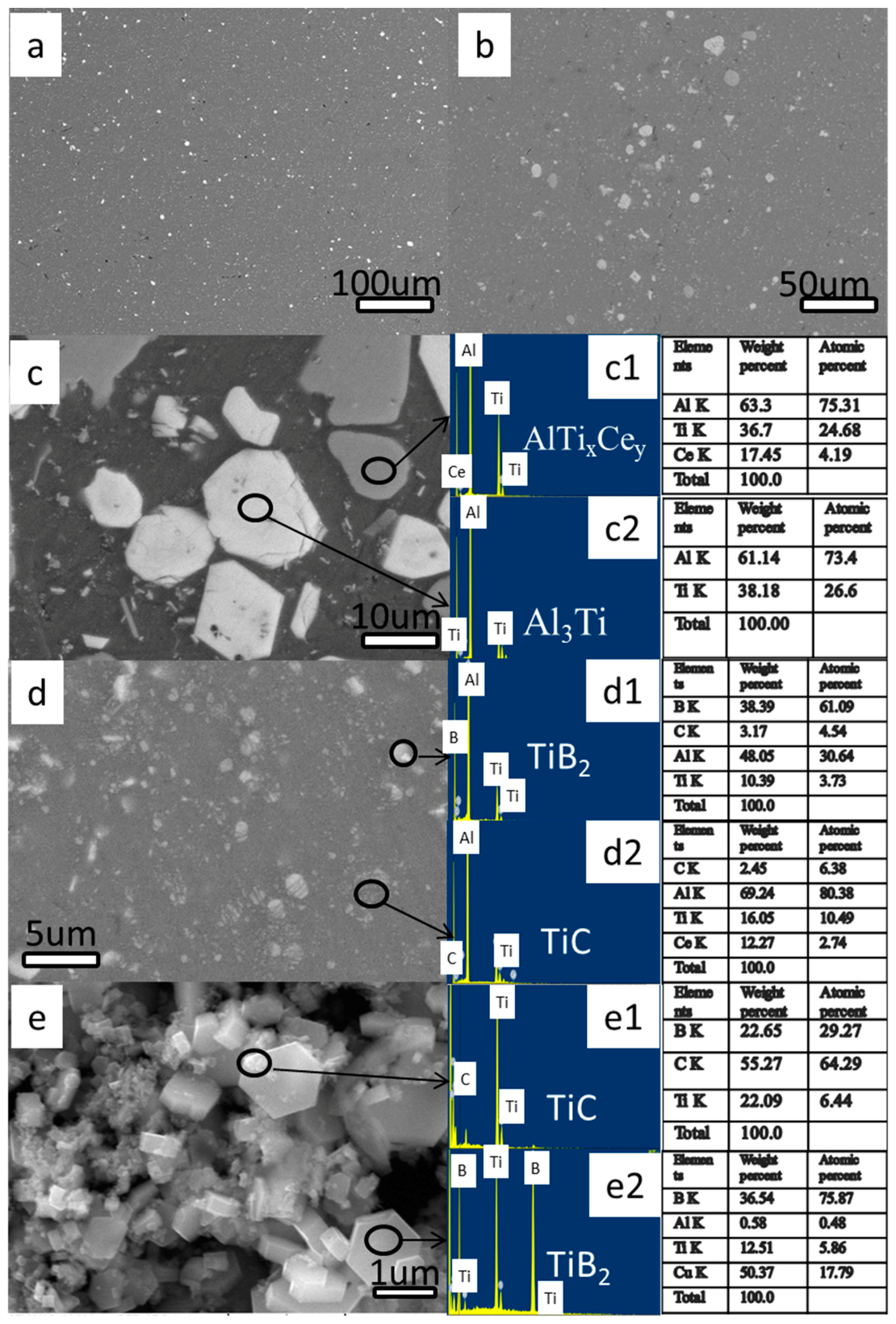
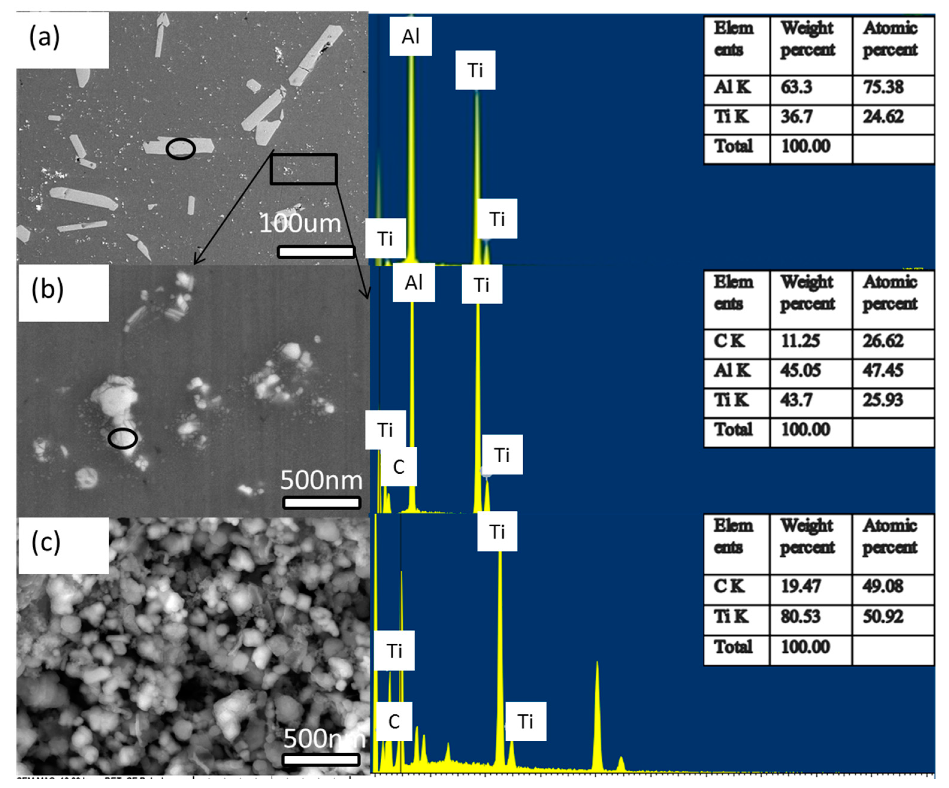
Figure 2 shows the X-ray diffraction of the Al-Ti-C intermediate alloy. The XRD results show that there were Al, Al3Ti, and TiC phases present in the Al-Ti-C intermediate alloy, prepared by the in-situ reaction.

3.1.2. SEM Analysis

Figure 3 demonstrates a scan of the Al-Ti-C intermediate alloy, and energy spectral analysis of the different phases. The micrograph showed that the dimension of the long stripe phase was about 20–50 μm, and the maximum dimension of the small particle phase was approximately 1 μm. Figure 3a shows the energy spectrum of the long rod phase. The atomic ratio of Al:Ti was 3:1, and the long rod phase is Al3Ti. Figure 3b shows the energy spectrum of the small particle phase. Herein, the grayish white near spherical nano-phase is TiC (Ti:C = 1:1). At 1200 °C, Ti and graphite react violently in the alloy melt, and a large amount of TiC crystals are formed in the early phase of the reaction. The spherical clusters mainly comprise Ti and C, with Ti:C = 49.08:50.92, which is close to the Ti:C ratio in the TiC compound. From the XRD results, it is believed that the spherical clusters are TiC phases. The reasons for the clustering may be that, in small particles, the large specific surface area leads to a high specific surface energy and they cluster to reduce the specific surface area and energy. In the meantime, calculations made using Image Pro showed that the volume fraction of Ti phase in the alloy was about 10.5%. Figure 3c shows the SEM image of the extracted Al-Ti-C intermediate alloy. Since the matrix had been dissolved and the other large phases were also removed by sieving, only TiC remained. The figure shows that TiC was mostly irregularly granular. Since the specimen was adsorbed on the copper mesh after extraction, the energy spectrum showed a strong uncalibrated Cu peak.

3.1.3. TEM Analysis

TiC is a face-centered cubic crystal; its close packed plane and close packed direction are {111} and [110], respectively. Since the (111) plane is a regular hexagonal base plane, the growth of a complete hexagonal TiC crystal is along the [111] direction, i.e., a coarse hexagonal TiC crystal grain is formed by hexagonal monolayers in a layered growth pattern along the [111] crystallographic direction. The formation of such a thick hexagonal TiC crystal is shown schematically in Figure 4.
Figure 5 shows that the nano phases are distributed mainly on the grain boundaries. The size of the irregular hexagonal phase TiC was about 200 nm. At the same time, the diffraction pattern showed that the irregular hexagons mainly grew in the [011] and [21-1] directions.

3.2. Al-5Ti-B Intermediate Alloy Phase Analysis

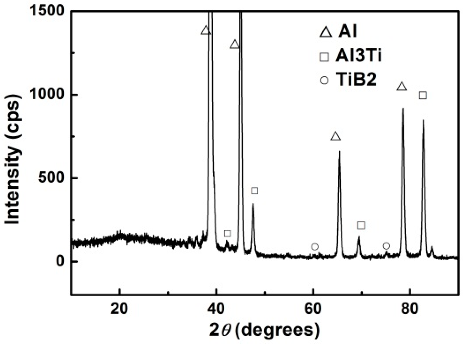
3.2.1. X-ray Diffraction Analysis

Figure 6 shows the XRD results of Al-Ti-B master alloy. The XRD results showed that there were Al, Al3Ti, and TiB2 phases in the Al-Ti-B intermediate alloy, produced by the in-situ reaction.

3.2.2. SEM Analysis

Figure 7 shows the scan image of the Al-Ti-B intermediate alloy. It can be seen that there were two phases that were different in morphology and size, one of which was in the shape of a rod and the other was in the form of a grain. Figure 8 shows the scan image and energy spectrum of different phases. The energy spectrum showed that the atomic ratio of Al to Ti in the rod-shaped phase was 3:1. Further analysis showed that the long rod phase was Al3Ti and the small grain was TiB2. Furthermore, the extracted photos suggested that the granular TiB2 was an irregular polygon with a constant thickness. The volume fraction of the Ti phase in the Al-Ti-B alloy was about 16.5%. Moreover, the Al3Ti particles in Al-Ti-B alloy were smaller than the Al3Ti particles in Al-Ti-C.

3.2.3. TEM Analysis

Figure 9 shows the TEM and diffraction patterns of Al-Ti-B intermediate alloy. It showed that the nano-phase resides at the grain boundary and that the size of TiB2 was about 200 nm. Moreover, there was a certain phase relationship between the Al (111) direction and the TiB2 (100) direction.

3.3. Al-5Ti-B-C-Ce Phase Analysis

3.3.1. XRD Analysis

Figure 10 exhibits the X-ray diffraction pattern of Al-5Ti-B-C-Ce alloy. It indicated that the Al-Ti-B-C-Ce alloy included Al, Al3Ti, TiB2, and TiC phases. No Ce-containing phase was detected in the X-ray diffraction of Al-5Ti-B-C-Ce, due to the relatively low content of element Ce, which was only confirmed by energy spectrum analysis.

3.3.2. SEM Analysis

Figure 11 shows the SEM image of the Al-5Ti-BC-Ce alloy specimen and EDX analysis. Figure 11a,b suggests that the nano-reinforcing particulates are distributed in the form of clusters. The particulates are small but numerous. The solidification process of the aluminum melt can provide more nucleation particles, which can be used as an effective intra-crystalline reinforcement to improve the performance of the alloy. The dark regions of the image are the aluminum substrates, and the bright colors refer to the ceramic particles. In Figure 11c1, the larger particles are found to be Al3Ti from energy spectrum analysis. Figure 11c2 shows that trace amounts of rare earth element Ce can inhibit the rod-shaped Al3Ti phase (80 µm is reduced to about 10 µm) and generate the Ti2Al20Ce phase. The energy spectrum of Figure 11d1, demonstrates that elements B and Ti are high in weight percentage, indicating that the larger particles in Figure 11d are TiB2. Figure 11d2 shows that the weight percentage of elements C and Ti are high, indicating that the gray spot particles in Figure 11d are TiC. Figure 11e is the photomicrographs of the same extraction, showing a hexagonal prismatic phase, with numerous fine granular compounds attached around the hexagonal prism. The energy spectral analysis showed that it is composed of elements Ti, B, Al, and Cu, and has a high content of elements B, Al, and Cu in the spectrum, which are generated by the matrix and the net; therefore, the hexagonal prism is TiB2. The energy spectrum analysis of the particles attached to the surface of the hexagonal prism, showed that it is composed of elements Ti, C, and B. The generation of B was mainly due to the small phase generated by the hexagonal prism. Therefore, the attached particles were TiC compounds. The energy spectrum analysis of the particles near the hexagonal prism, revealed that the particles were composed of elements C, Ti, and B, and the C content was high; so these fine particles were TiC phases. The results of scanning electron micrographs and energy spectra provided initial confirmation that TiB2, TiC, and Al3Ti particles were contained in the Al-5Ti-B-C-Ce alloy. The scan images also revealed the morphology of TiB2 and TiC. Compared to Al-5Ti-C alone, the Al-5Ti-B and Al-5Ti-B-C-Ce phases were smaller and more uniform.
In the early formation stage of the TiC phase, in the high-temperature in situ reaction in the molten alloy, the TiC structure itself contains many C vacancies [34]. This caused instability in the TiC phase structure and poor reinforcement efficiency. According to reports, TiC can degrade rapidly in 30 min. Element B is adjacent to C in the periodic table and has similar properties. In a melt, element B may diffuse and blend into the TiC lattice. This provides a prerequisite for doping with small- sized B atoms, and a way to control the structure and performance of the TiC reinforcement phase. The size of TiC is about 200 nm and the size of TiB2 ranges from 200–900 nm.

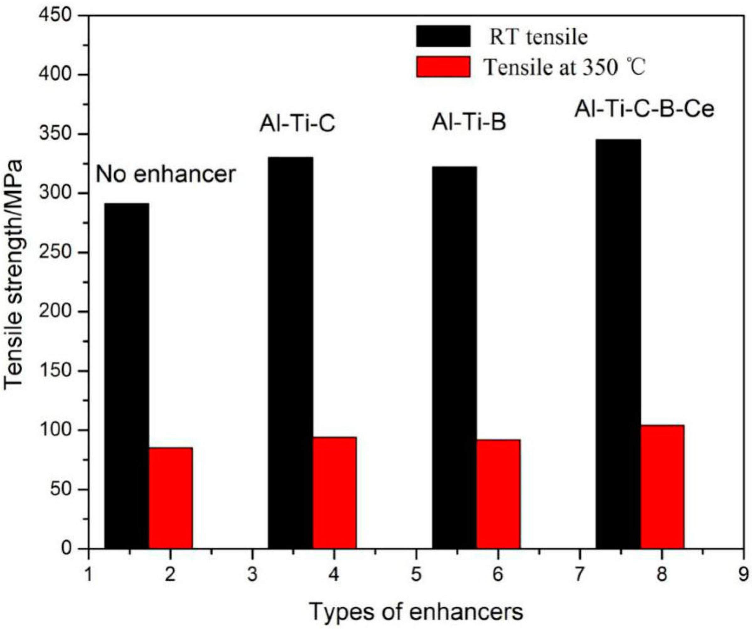
3.4. Effects of Three Different Reinforcements on the Tensile Properties of the Al Alloy

Figure 12 is a bar graph showing the tensile strength of the Al-13Si-4Cu-1Mg-2Ni aluminum alloy cast piston, with three different reinforcements. The RT tensile strength increased by 13.8%, 8.6%, and 19.0%, respectively. The 350 °C tensile strength increased by 3.4%, 2.3%, and 18.4%, respectively. It revealed that all three reinforcements were effective, and that the addition of Al-5Ti-B-C-Ce reinforcement was more effective than the other two reinforcements, in increasing the room temperature and high-temperature tensile strength.

3.5. Strengthening Mechanism

In the process of solidification of the aluminum alloy, the dissolution and formation of intermetallic compounds will be formed, and the formed or added heteromorphic nuclear particles can be uniformly dispersed in the matrix alloy to promote the nucleation. By increasing the nucleation core of the non-uniform nucleation, it is precisely the principle of adding reinforcement to the matrix to refine the grain.
These lumpy Al3Ti particles are block phase, which can cause cleavage phenomenon in the grain boundary and seriously affect the properties of the aluminum alloy [35]. To improve the performance of single Al-Ti-C and Al-Ti-B, the Al-Ti-B-C-Ce hybrid enhancement was prepared, which made TiC and TiB2 play a double enhancement role. Simultaneously, the rare earths surface active elements can increase the wetting angle, improve the wettability of boride aluminum liquid, are easy to gather on the phase interface and grain interface adsorption, can fill in the surface of the grain defect, whilst making the grain continue to grow unhampered leading to the refinement of grain. Rare earth Ce, also has the effect of degassing (deoxygenation) [36,37]. In this way, TiC and TiB2 are improved in the aluminum solution and the strength of the alloy is improved.

4. Conclusions

In this paper, three different kinds of reinforcements Al-Ti-C, Al-Ti-B, and Al-Ti-B-C-Ce were added to the alloy Al-13Si-4Cu-1Mg-2Ni, to compare its strengthening effect. The three reinforcements were also analyzed by SEM and TEM. The results are summarized as follows:
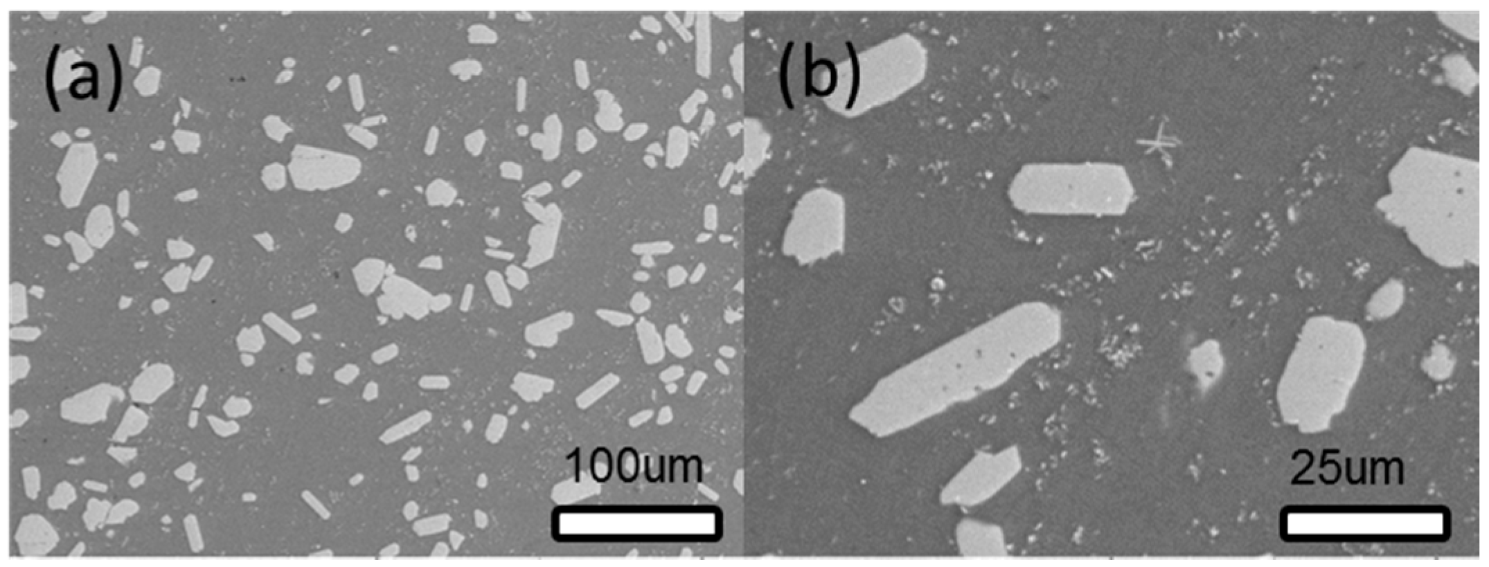
  • After doping with trace amounts of elements B and Ce, the size of reinforcement Al3Ti phase changed from 80 µm (un-reinforced) to about 10 µm, with the simultaneous formation of Ti2Al20Ce phase.
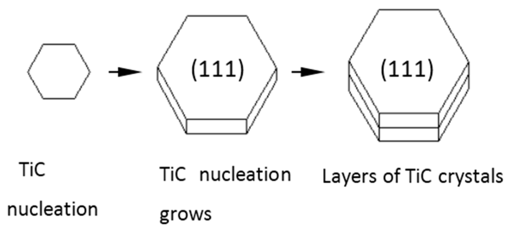
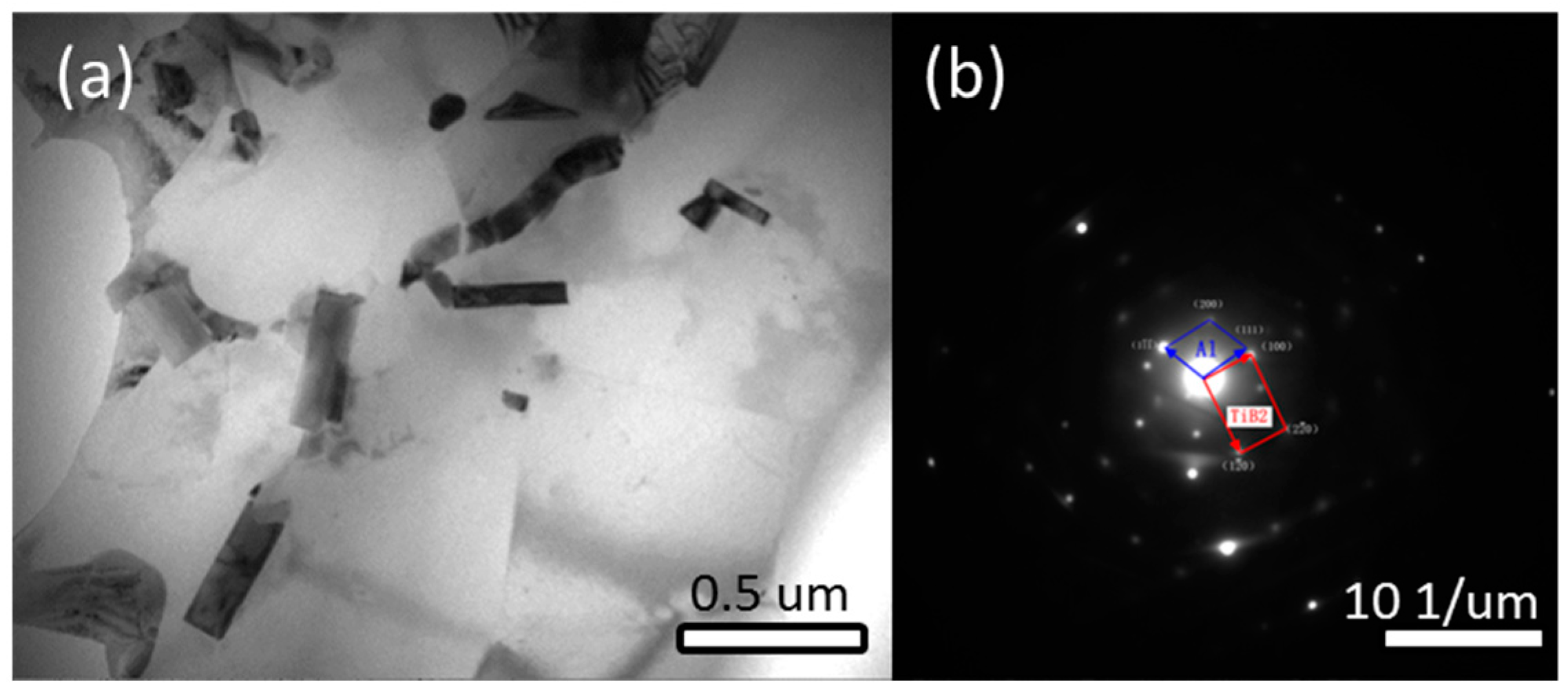
  • Since doping with element B destroys the equilibrium growth conditions for TiC phase, small nano phases of TiC attached to the surface and vicinity of hexagonal TiB2. Compared with alloy without element B doping, the hexagonal TiB2 phase turns out to be a growth carrier for TiC nano-phase, and the distribution of TiC nano-phase is more uniform.
  • All three in situ reinforcements were effective to the Al-13Si-4Cu-2Ni-1Mg alloy, and the addition of Al-5Ti-B-C-Ce reinforcement was more effective than the other two reinforcements in increasing the room temperature and high-temperature tensile strength. The RT strength increased by 19.0%, and the 350 °C-strength increased by 18.4%.

Author Contributions

L.T. wrote the main part of the manuscript and took part in the planning and execution of the experiments. Y.G. conceived and designed the study. J.L. participated in the coordination of the study and reviewed the manuscript. F.X. carried provided experimental alloys and analytical samples. M.L. analyzed part of experimental results. Transmission experiments were carried by H.D., P.W. and J.W. performed performance tests and made a final examination of the article.

Funding

The authors would like to thank financial support by the Creative Talents Promotion Plan—Technological Innovation Team (2017KCT-05), key research and development plan of Shaanxi province- Industrial project (2018GY-111) and key research and development plan of Shaanxi province project (2018ZDXM-GY-137).

Conflicts of Interest

The authors declare no conflicts of interest.

References

  1. Clyne, T.W.; Withers, P.J. An Introduction to Metal Matrix Composites: Applications; Cambridge University Press: Cambridge, UK, 1993; p. 454. [Google Scholar]
  2. Moore, J.J.; Feng, H.J. Combustion synthesis of advanced materials: Part I. Reaction parameters. J. Prog. Mater Sci. 1995, 39, 243–273. [Google Scholar] [CrossRef]
  3. Merzhanov, A.G. Self-propagating high temperature synthesis and powder metallurgy: Unity of goals and competition of principles. Adv. Powder Metall. Part Mater. 1992, 9, 341–368. [Google Scholar]
  4. Merzhanov, A.G. Academician. Processes of self-propagating high-temperature synthesis at new frontiers Academician. Ind. Ceram. 2009, 29, 196–199. [Google Scholar]
  5. Nampoothiri, J.; Harini, R.S.; Nayak, S.K.; Raj, B.; Ravi, K.R. Post in-situ reaction ultrasonic treatment for generation of Al-4.4Cu/TiB2 nanocomposite: A route to enhance the strength of metal matrix nanocomposite. J. Alloys Compd. 2016, 683, 370–378. [Google Scholar] [CrossRef]
  6. Tjong, S.C.; Mai, Y.W. Processing-structure-property aspects of particulate and whisker-reinforced titanium matrix composites. Compos. Sci. Technol. 2008, 68, 583–601. [Google Scholar] [CrossRef]
  7. Ramesh, C.S.; Keshavamurthy, R.; Channabasappa, B.H.; Pramod, S. Influence of heat treatment on slurry erosive wear resistance of Al6061 alloy. Mater. Des. 2009, 30, 3713–3722. [Google Scholar] [CrossRef]
  8. Macke, A.; Schultz, B.F.; Rohatgi, P. Metal matrix composites offer the auto-motive industry an opportunity to reduce vehicle weight, improve performance. Adv. Mater. Processes 2012, 170, 19–23. [Google Scholar]
  9. Yang, J.; Pan, L.; Gu, W.; Qiu, T.; Zhang, Y. Microstructure and mechanical properties of in situ synthesized (TiB2 + TiC)/Ti3SiC2 composites. Ceram. Int. 2012, 38, 649–655. [Google Scholar] [CrossRef]
  10. Choi, Y.; Rhee, S.W. Effect of carbon sources on the combustion synthesis of TiC. J. Mater. Sci. 1993, 28, 6669–6675. [Google Scholar] [CrossRef]
  11. Kaftelen, H.; Unlu, N.; Goller, G. Comparative processing-structure–property studies of Al-Cu matrix composites reinforced with TiC particulates. Compos. Part A Appl. Sci. Manuf. 2011, 42, 812–824. [Google Scholar] [CrossRef]
  12. Liu, Z.; Han, Q.; Li, J. Fabrication of in situ Al3Ti/Al composites by using ultrasound assisted direct reaction between solid Ti powders and liquid Al. Powder Technol. 2013, 247, 55–59. [Google Scholar] [CrossRef]
  13. Tang, P.; Li, W.F.; Wang, K.; Du, J.; Chen, X.Y.; Zhao, Y.J.; Li, W.Z. Effect of Al-Ti-C master alloy addition on microstructures and mechanical properties of cast eutectic Al-Si-Fe-Cu alloy. Mater. Des. 2017, 115, 147–157. [Google Scholar] [CrossRef]
  14. Sadeghi, E.; Karimzadeh, F.; Abbasi, M.H. Thermodynamic analysis of Ti-Al-C intermetallics formation by mechanical alloying. J. Alloys Compd. 2013, 576, 317–323. [Google Scholar] [CrossRef]
  15. Rai, R.N.; Datta, G.L.; Chakraborty, M.; Chattopadhyay, A.B. A study on the machinability behaviour of Al-TiC composite prepared by in situ technique. Mater. Sci. Eng. A 2006, 428, 34–40. [Google Scholar] [CrossRef]
  16. Li, P.T.; Li, Y.G.; Wu, Y.Y.; Ma, G.L.; Liu, X.F. Distribution of TiB2 particles and its effect on the mechanical properties of A390 alloy. Mater. Sci. Eng. A 2012, 546, 146–152. [Google Scholar] [CrossRef]
  17. Liu, Z.D.; Tian, J.; Li, B.; Zhao, L.P. Microstrcuture and mechanical behaviors of in situ TiC particulates reinforced Ni matrix composites. Mater. Sci. Eng. A 2010, 527, 3898–3903. [Google Scholar] [CrossRef]
  18. Wangjara, P. Characterization of Ti-6% Al-4%V/TiC Particulate Reinforced Metal Matrix Composites Consolidated by Sintering and Thermomechanical Processing. Ph.D. Thesis, Mcgill University, Montreal, QC, Canada, 1999. [Google Scholar]
  19. Pearson, W.B. A Handbook of Lattice Spacings and Structures of Metals and Alloys; Pergamon Press: Oxford, UK, 1958. [Google Scholar]
  20. Ramesh, C.S.; Pramod, S.; Keshavamurthy, R. A study on microstructure and mechanical properties of Al 6061—TiB2 in-situ composites. Mater. Sci. Eng. A 2011, 528, 4125–4132. [Google Scholar] [CrossRef]
  21. Wang, E.Z.; Gao, T.; Nie, J.F.; Liu, X.F. Grain refinement limit and mechanical properties of 6063 alloy inoculated by Al-Ti-C (B) master alloys. J. Alloys Compd. 2014, 594, 7–11. [Google Scholar] [CrossRef]
  22. Zhao, H.L.; Song, Y.; Li, M.; Guan, S.K. Grain refining efficiency and microstructure of Al-Ti-C-RE master alloy. J. Alloys Compd. 2010, 508, 206–211. [Google Scholar] [CrossRef]
  23. Tabrizi, S.G.; Sajjadi, S.A.; Babakhani, A.; Lu, W. Influence of spark plasma sintering and subsequent hot rolling on microstructure and flexural behavior of in-situ TiB and TiC reinforced Ti6Al4V composite. Mater. Sci. Eng. A 2015, 624, 271–278. [Google Scholar] [CrossRef]
  24. El-Mahallawy, N.; Taha, M.A.; Jarfors, A.E.W.; Fredriksson, H. On the reaction between aluminium K2TiF6 and KBF4. J. Alloys Compd. 1999, 292, 221–229. [Google Scholar] [CrossRef]
  25. Xuan, Q.Q.; Shu, S.L.; Qiu, F.; Jin, S.B.; Jiang, Q.C. Different strain-rate dependent compressive properties and work-hardening capacities of 50 vol% TiCx/Al and TiB2/Al composites. Mater. Sci. Eng. A. 2012, 538, 335–339. [Google Scholar] [CrossRef]
  26. Gao, Q.; Wu, S.S.; Lu, S.L.; Duan, X.C.; Zhong, Z.Y. Preparation of in-situ TiB2 and Mg2Si hybrid particulates reinforced Al-matrix composites. J. Alloys Compd. 2015, 651, 521–527. [Google Scholar] [CrossRef]
  27. Nie, J.F.; Liu, X.F.; Ma, X.G. Influence of trace boron on the morphology of titanium carbide in an Al-Ti-C-B master alloy. J. Alloys Compd. 2010, 491, 113–117. [Google Scholar] [CrossRef]
  28. Wu, Z.S. Preparation and Properties of TiC-Based Composites. Ph.D. Thesis, Jiangsu University, Nanjing, China, 2004. [Google Scholar]
  29. Ma, M.Z.; Cai, D.Y.; Wei, T.H. Microstructure and mechanical properties of TiCp/Al-4.5Cu-0.8Mg compsites by direct reaction synthesis. J. Mater. Sci. Technol. 2003, 19, 447–449. [Google Scholar]
  30. Le, Y.K.; Zhang, Y.Y. Research status of particle reinforced aluminum matrix composites. Dev. Appl. 1997, 5, 33–37. [Google Scholar]
  31. Tee, K.L.; Lu, L.; Lai, M.O. Synthesis of in situ Al-TiB2 composites using stir cast route. Compos. Struct. 1999, 47, 589–593. [Google Scholar] [CrossRef]
  32. Mandal, A.; Chakraborty, M.; Murty, B.S. Ageing behaviour of A356 alloy reinforced with in-situ formed TiB2 particles. Mater. Sci. Eng. A 2008, 489, 220–226. [Google Scholar] [CrossRef]
  33. Zhao, D.G.; Liu, X.F.; Bian, X.F. Preparation and mechanical properties of TiB2 + SiC/ZL109. Casting 2004, 53, 97–100. [Google Scholar]
  34. Song, W.; Wang, L.; Chen, X.; Chen, Y.; Li, Q. Effects of Al-Ti-C-Ce master alloy on As-cast microstructure and mechanical properties of 7010 aluminum alloy. Spec. Cast. Nonferrous Alloy 2011, 4, 39. [Google Scholar]
  35. Cheng, L.H.; Sun, Y.; Sun, G.X. Effect of Al-5Ti-1B on the microstructure of near-eutectic Al-13%Si alloys modified with Sr. J. Mater. Sci. 2002, 37, 3489–3495. [Google Scholar]
  36. Wang, K.; Cui, C.; Wang, Q.; Liu, S.; Gu, C. The microstructure and formation mechanism of core–shell-like TiAl3/Ti2Al20Ce in melt-spun Al-Ti-B-Re grain refiner. Mater. Lett. 2012, 85, 153–156. [Google Scholar] [CrossRef]
  37. Yin, J.B.; Li, Y.T.; Bi, J.M.; Pang, X.Z.; Li, L.J. Research on grain refinement of Al-2Ti-B-Ce and Al-5Ti-B-Ce master alloys on industrial pure aluminum. Light Alloy Fabr. Technol. 2015, 1, 5. [Google Scholar]
Figure 1. The preparation technology of composite alloy.
Applsci 08 01523 g001
Figure 2. XRD analysis of Al-Ti-C intermediate alloy.
Applsci 08 01523 g002
Figure 3. SEM micrograph and energy spectrum: (a) rod-like Al3Ti phase; (b) grain-like TiC phase; (c) extracted TiC.
Applsci 08 01523 g003
Figure 4. Schematic of the growth process of the hexagonal TiC crystal layers.
Applsci 08 01523 g004
Figure 5. Nano-phase distribution and identification of diffraction spots. (a) TEM images of the nano phase; (b) diffraction spots of nano phase; (c) TEM images of the nano phase; (d) diffraction spots of nano phase.
Applsci 08 01523 g005
Figure 6. XRD spectrum of Al-Ti-B intermediate alloy.
Applsci 08 01523 g006
Figure 7. SEM image of the Al-Ti-B alloy. (a) Low magnification SEM; (b) High magnification SEM.
Applsci 08 01523 g007
Figure 8. SEM image and energy spectrum of different phases: (a) rod-shaped Al3Ti; (b) grain-shaped TiB2; (c) extracted TiB2.
Applsci 08 01523 g008
Figure 9. The TEM and diffraction patterns of Al-Ti-B intermediate alloy. (a) Low magnification SEM, (b) High magnification SEM.
Applsci 08 01523 g009
Figure 10. XRD spectrum of Al-Ti-B-C-Ce intermediate alloy.
Applsci 08 01523 g010
Figure 11. SEM images and EDX analysis of Al-5Ti-B-C-Ce alloy specimens SEM images and EDX analysis of Al-5Ti-B-C-Ce alloy specimens. (a) Low magnification SEM; (b) High magnification SEM; (c) nano phases; (c1) EDS of AlTixCey; (c2) EDS of Al3Ti; (d) nano phases; (d1) EDS of TiB2; (d2) EDS of TiC; (e)nano phases; (e1) EDS of TiC; (e2) EDS of TiB2.
Applsci 08 01523 g011
Figure 12. Tensile strengths of Al-13Si-4Cu-1Mg-2Ni alloy, with and without in situ reinforcements.
Applsci 08 01523 g012
Table 1. Properties of particle—enhancing compounds [17,18,19].
ParticleDensity/(g·cm−3)Melting Point/°CCoefficient of Thermal Expansion/ (10−6 °C−1)Thermal ConductivityElasticity Modulus/(GPa)
TiC4.9331607.7424.28450
TiB24.2529804.6–8.0124.4–26530
TiB4.524738.6-550
SiC3.1929704.3-430
VC5.3628104.224.7430
WC15.5527203.8429.31810
Al2O33.920508.628.89420
Al3Ti3.31623--220
Table 2. Characteristics of reinforcements.
Reinforcement TypesAdvantagesDisadvantages
Al-Ti-B
  • High refinement efficiency that is 12 times better than that of Al-Ti
  • TiAl3 and TiB2 are heterogeneous crystal cores of α(Al)
  • Accumulation of TiB2 can impair the quality
  • “Poisoning” by Zr, Cr, and Mn can lead to failure
Al-Ti-C
  • Non-contaminating addition of a refinement agent
  • “Immune” to Zr, Cr, and Mn
  • The grain size of TiC even smaller than that of TiB2
  • Poor attenuation
  • Refinement effect worse than that of Al-Ti-B
Al-Ti-B-C-Ce
  • They have all the above mentioned advantages
  • Particle size is refined by adding rare earth to prevent aggregation and precipitation of TiAl3 and TiB2
  • Research not yet well developed
Table 3. The tensile properties of different in-situ reinforced aluminum matrix composites at room temperature.
MaterialsEnhanced Phase Content/vol. %Tensile Strength/MPaElongationδ/%Reference
TiC/Al156104.9[28]
TiC/Al-4.5Cu2054018[29]
TiB2/Al163493.8[30]
TiB2/Al51249.2[31]
TiB2/A3562.529010[32]
TiB2/A35653029[32]
TiB2/A3567.53178[32]
TiB2/A356103286[32]
TiB2/ZL109-258.77.5[33]
Table 4. Raw materials for chemical reagents in the experiment.
PowdersParticle SizePurityManufacturer
Al200 mesh≥99.0%Shanghai shanpu chemical Co., Ltd. (Shanghai, China)
Ti200–300 mesh≥99.0%Sinopharm chemical reagent Co., Ltd. (Shanghai, China)
C2000 mesh≥99.9%Tianjin Kemiou Chemical Reagent Co., Ltd. (Tianjin, China)
K2TiF6/≥99.0%Shanghai SSS Reagent Co., Ltd. (Shanghai, China)
KBF4/≥99.0%Shanghai SSS Reagent Co., Ltd. (Shanghai, China)
B4C100–300 mesh≥99.0%Nangong ruiteng alloy material Co., Ltd. (Nangong, China)

