Fire Behavior of U-shaped Steel Beams Filled with Demolished Concrete Lumps and Fresh Concrete

Abstract
:1. Introduction
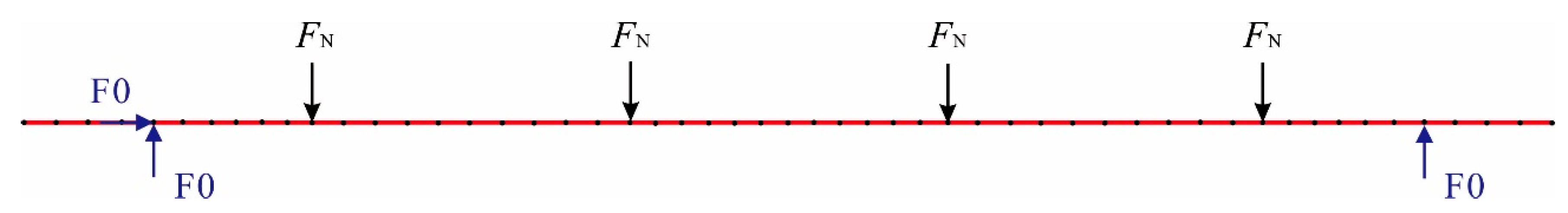
2. Experimental Program
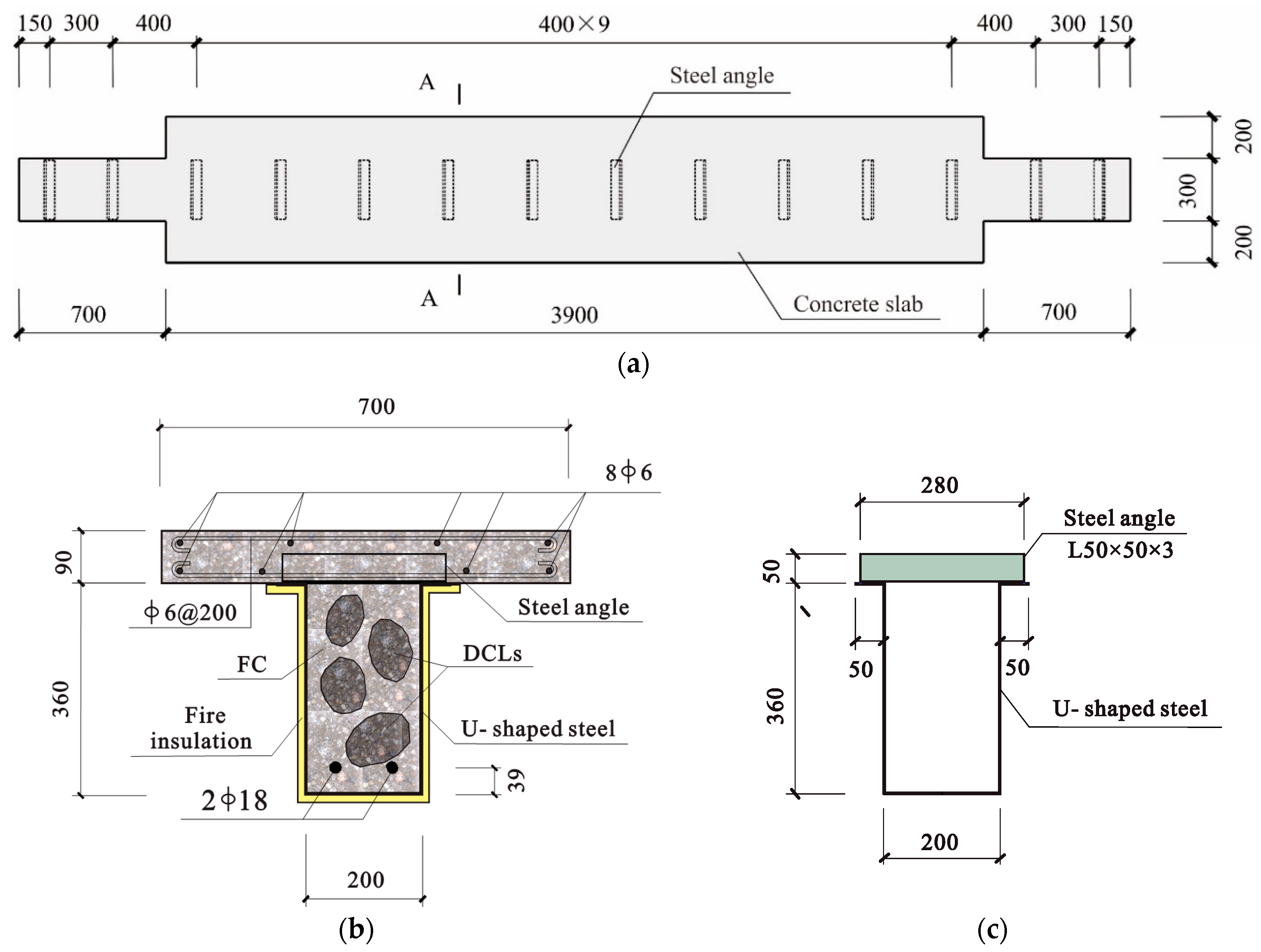
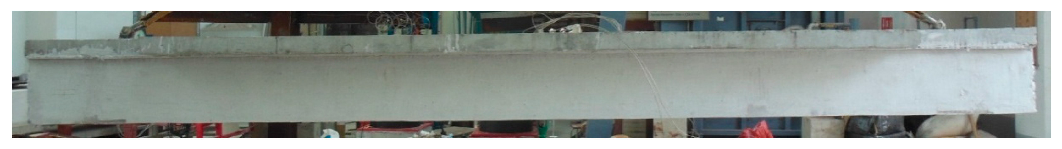
2.1. Test Specimens
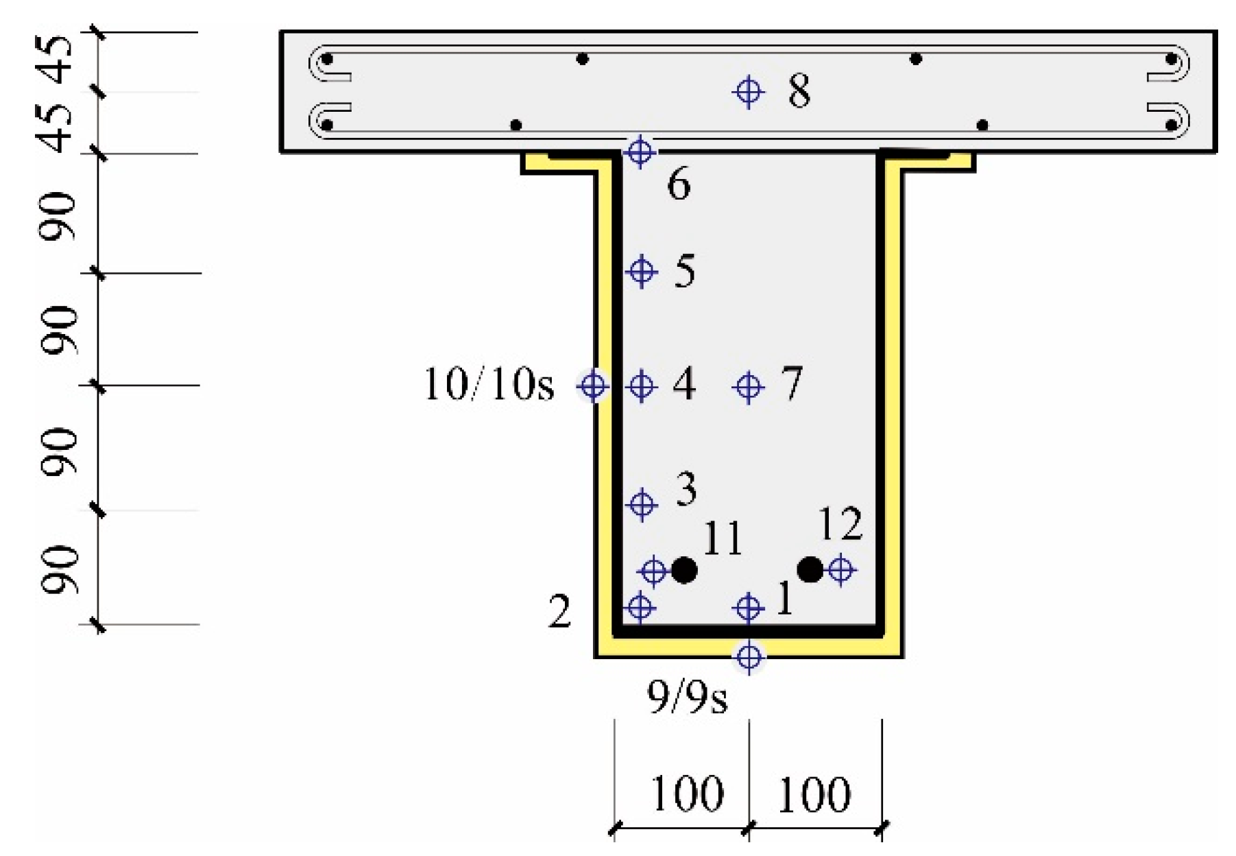
2.2. Test Setup and Procedure
3. Test Results and Discussions
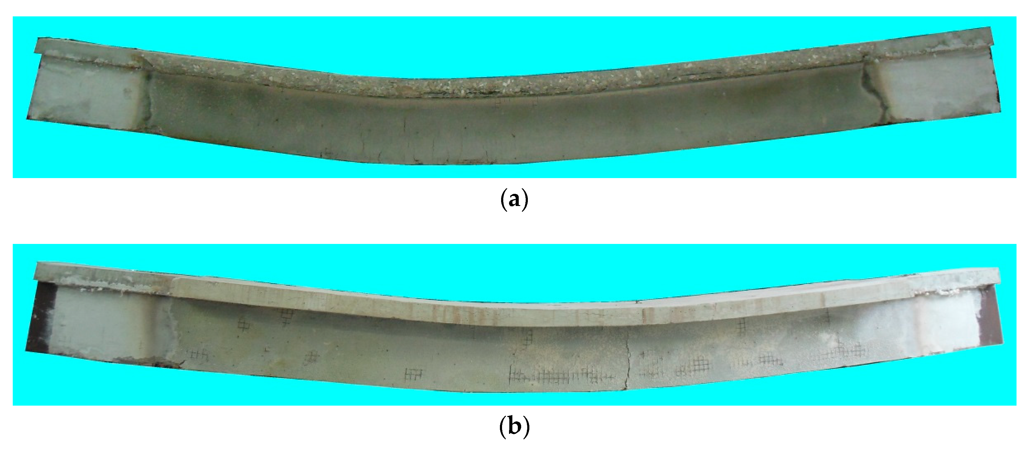
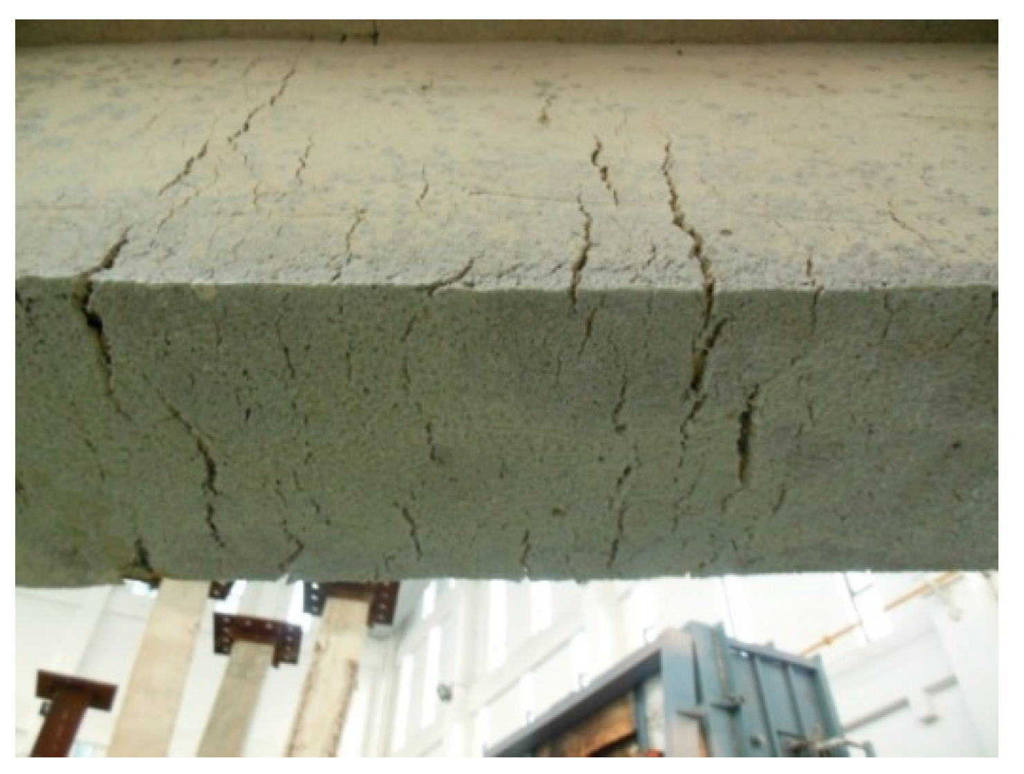
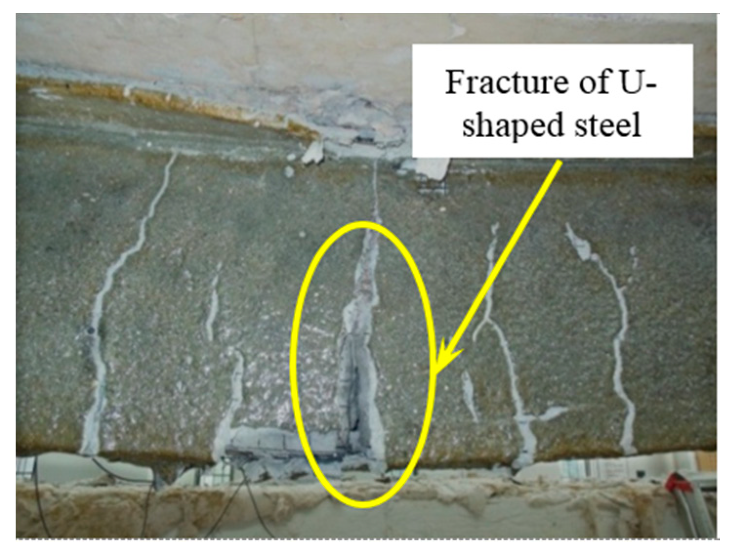
3.1. Test Observation
- (a).
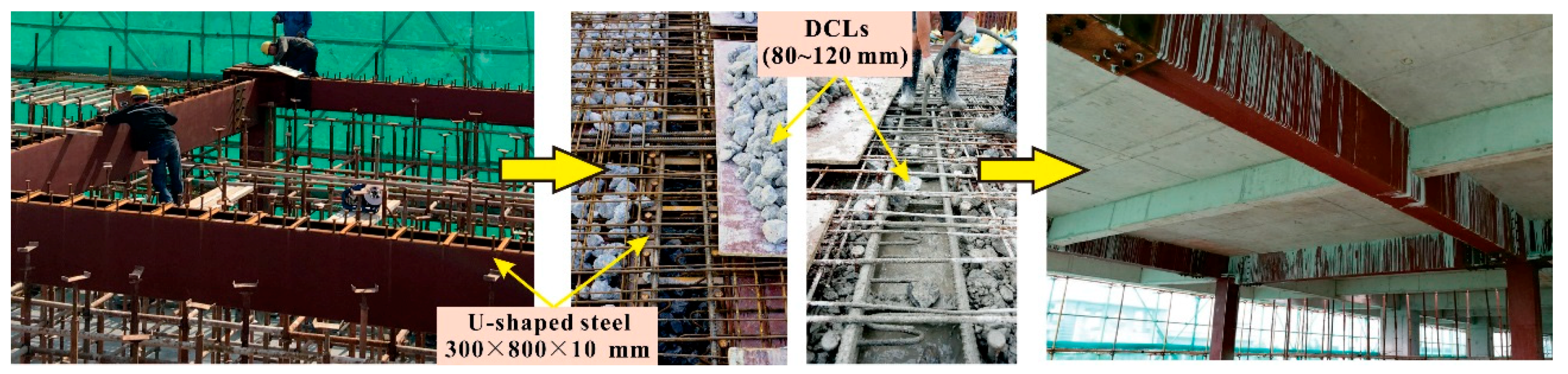
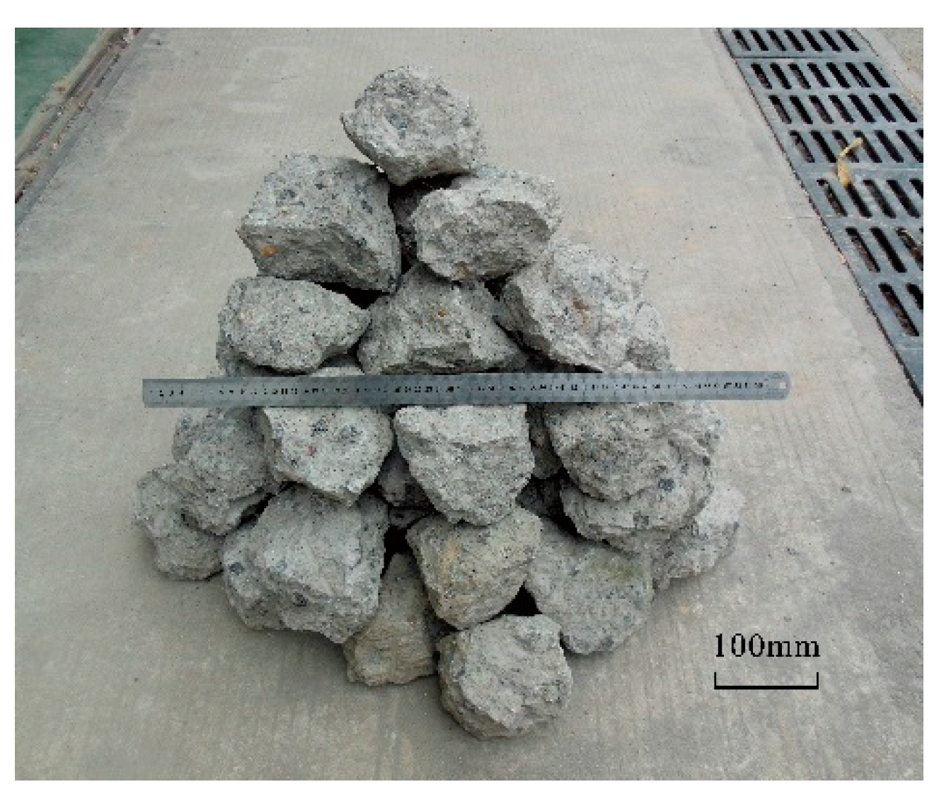
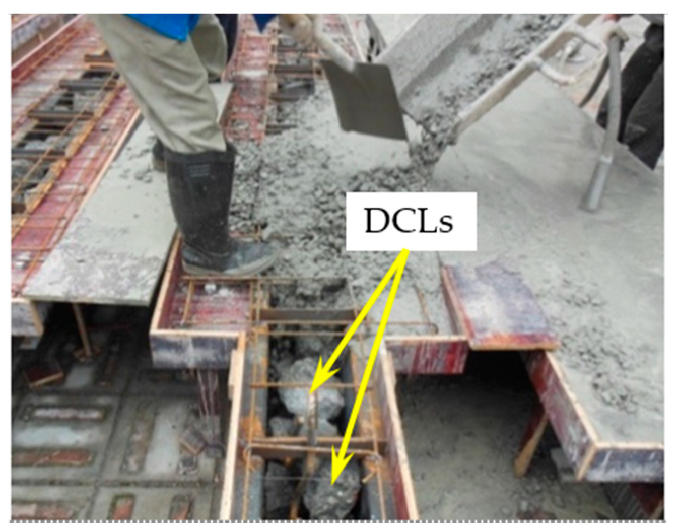
- The surface of the in-filled concrete is smooth and there are no obvious defects such as voids, holes, or pits on the surfaces or in the cut sections. This indicates that satisfactory construction quality can be achieved using the aforementioned concrete pouring method (all of the DCLs are put into the U-shaped steel at the same time and then the fresh concrete is poured with a continuous vibration).
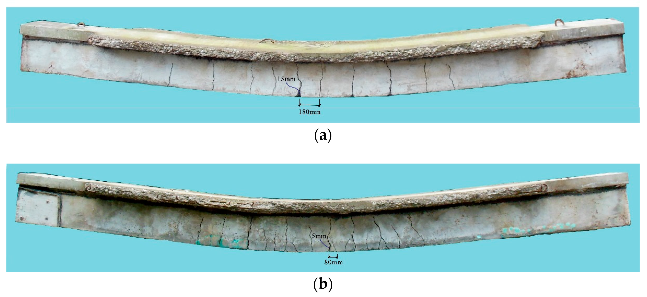
- (b).
- The flexural cracks propagate from the bottom of the beam to the slab. The minimum crack spacing and the maximum crack width of Specimen B3 are 180 mm and 15 mm, respectively. Specimen B4 shows more and narrower cracks due to the presence of the longitudinal reinforcements in the lower part of the beam. Its minimum crack spacing is 80 mm and the maximum crack width of Specimen B4 is 5 mm.
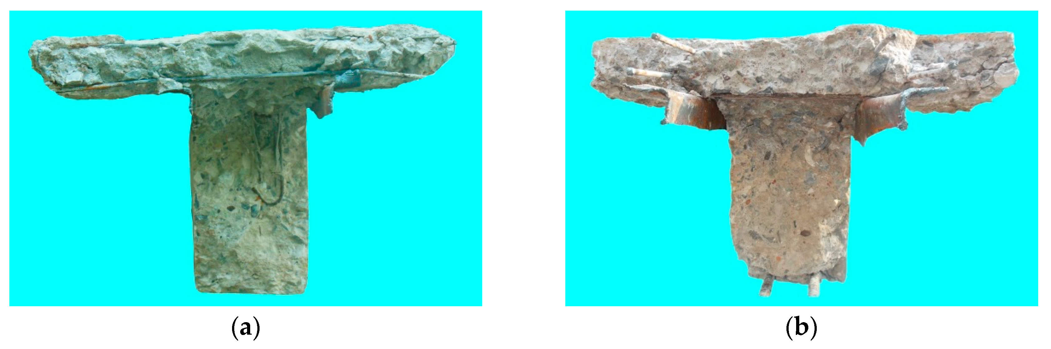
- (c).
- The cut sections of the in-filled concrete show that the DCLs and the FC bond well, which makes them work together.
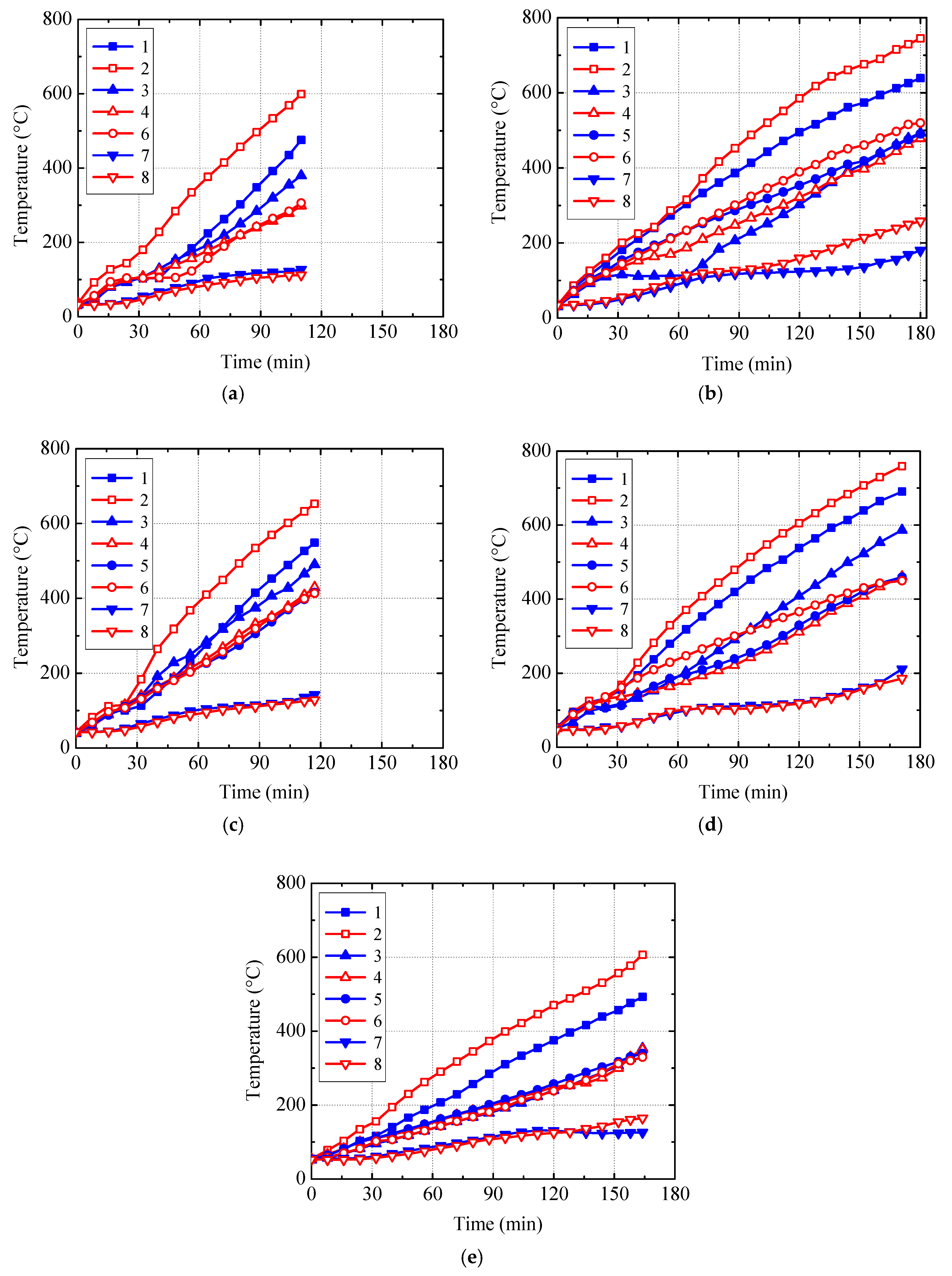
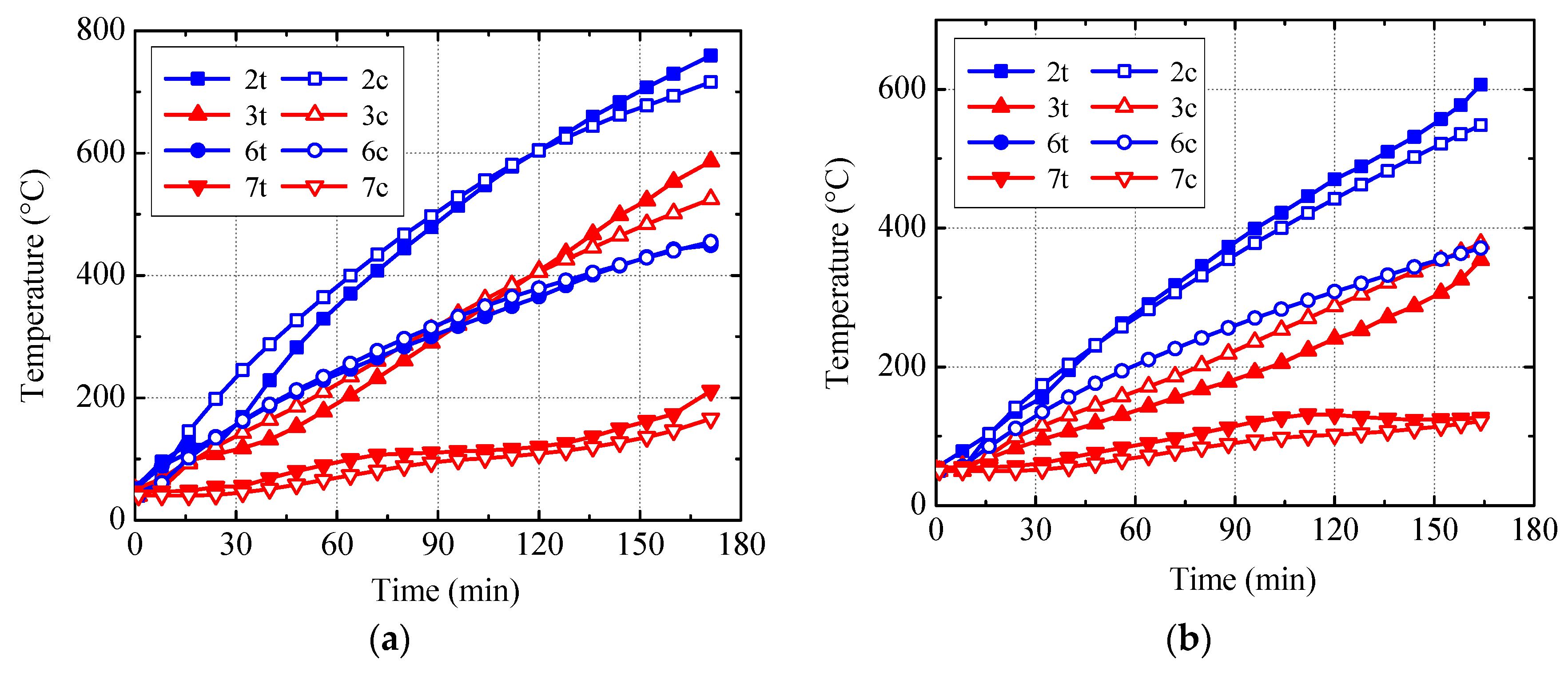
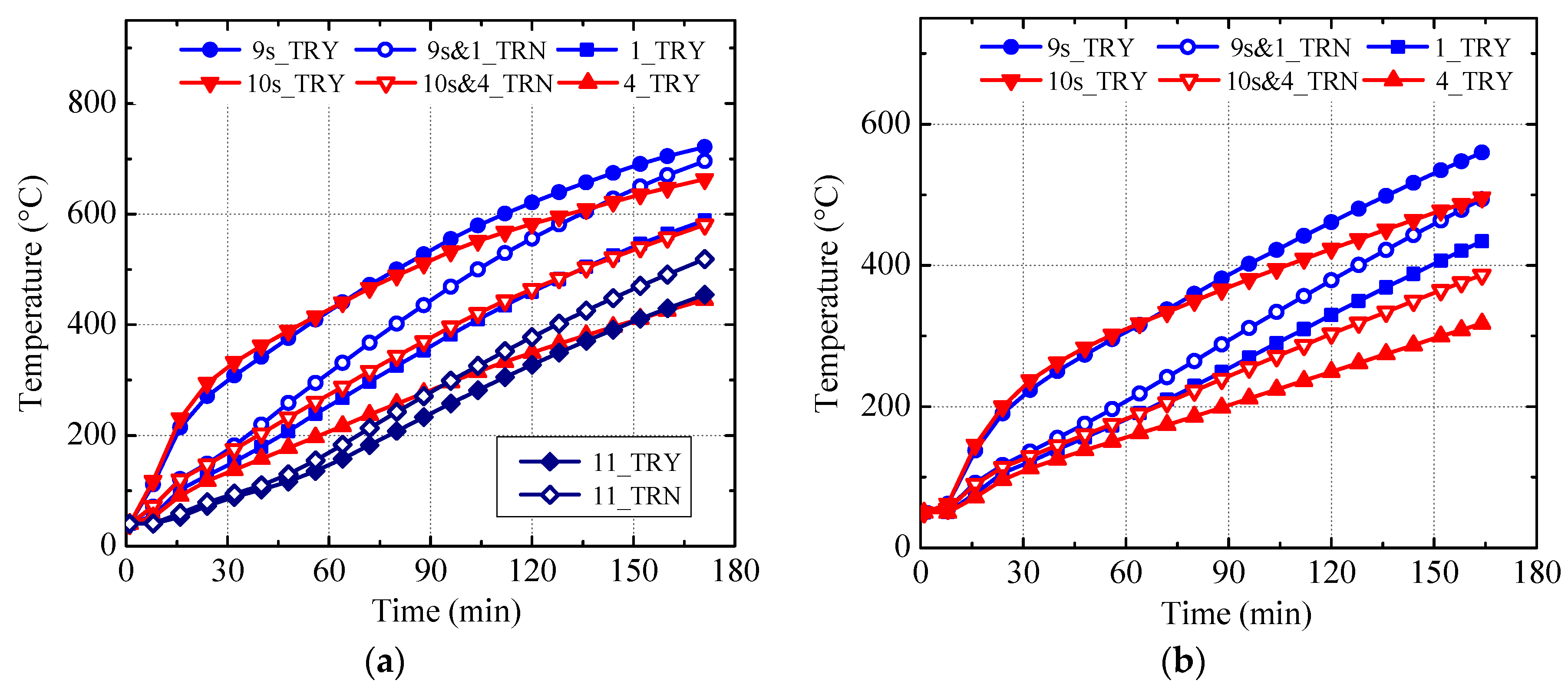
3.2. Thermal Response
- (a).
- The temperature-time curve related to Thermocouple 2, which was located at the corner of the in-filled concrete and subjected to 2-face heating, is generally higher than the others.
- (b).
- During the middle and later stages of the fire test, the temperature-time curve related to Thermocouple 1 located on the bottom surface of the in-filled concrete is generally higher than the curves of Thermocouples 3–6 located on the side surface. Heating from both sides of the beam raised the temperature of Thermocouple 1 relatively quickly.
- (c).
- The temperatures recorded by Thermocouples 4–6 are close to each other on the whole. Temperature differences between Thermocouples 2 and 4 vary between 200 °C and 300 °C in the later stage of the fire test, which indicates distinct temperature differences between different points on the surface of the in-filled concrete.
- (d).
- The temperatures measured by Thermocouples 7 and 8 (located at the center of the in-filled concrete and the center of the slab, respectively) are generally close to each other and increase slowly as the time goes on.
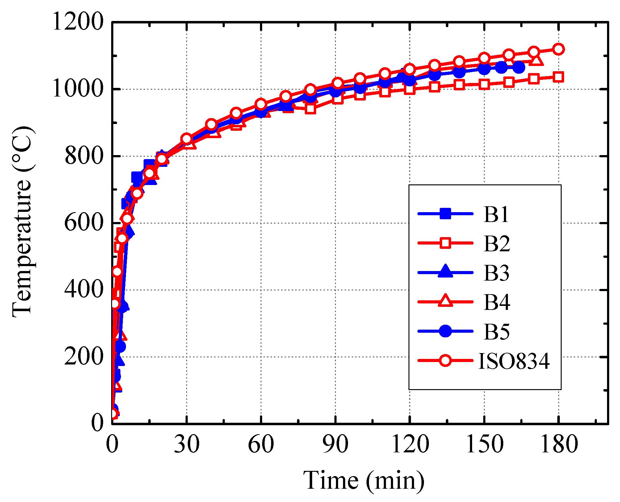
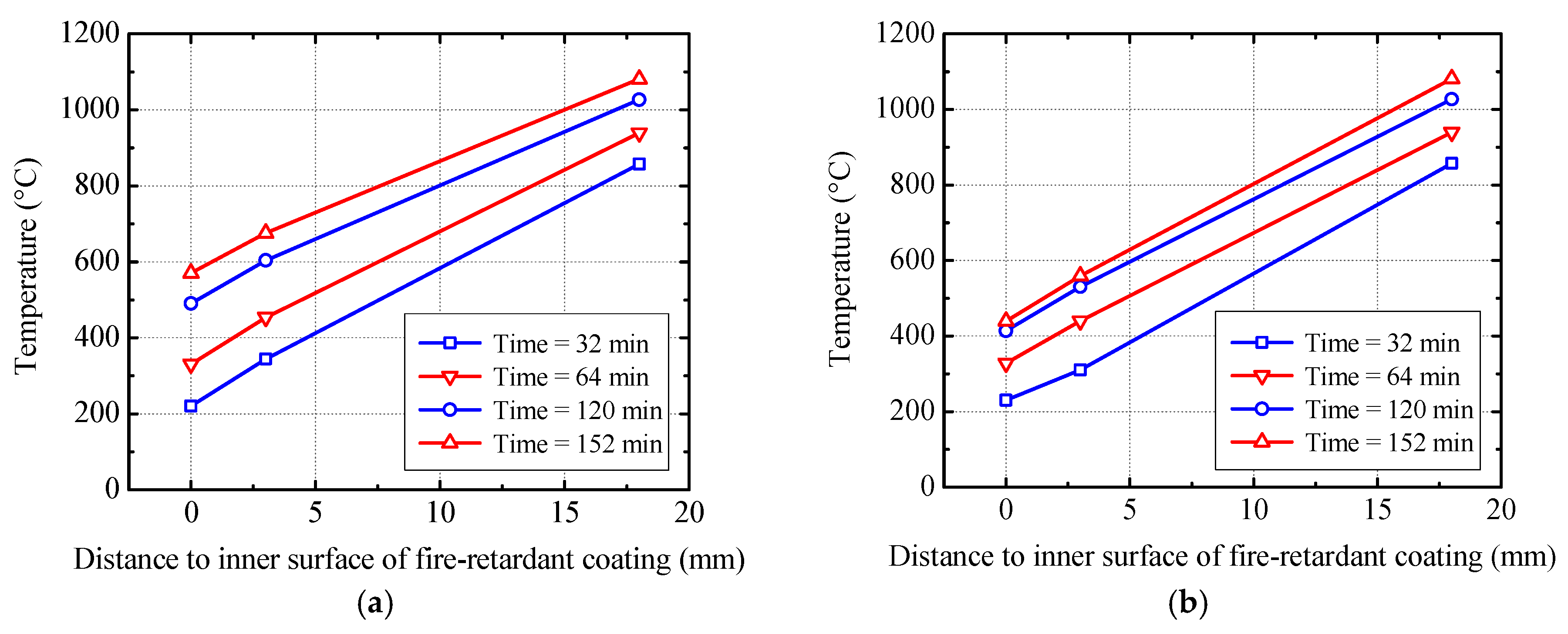
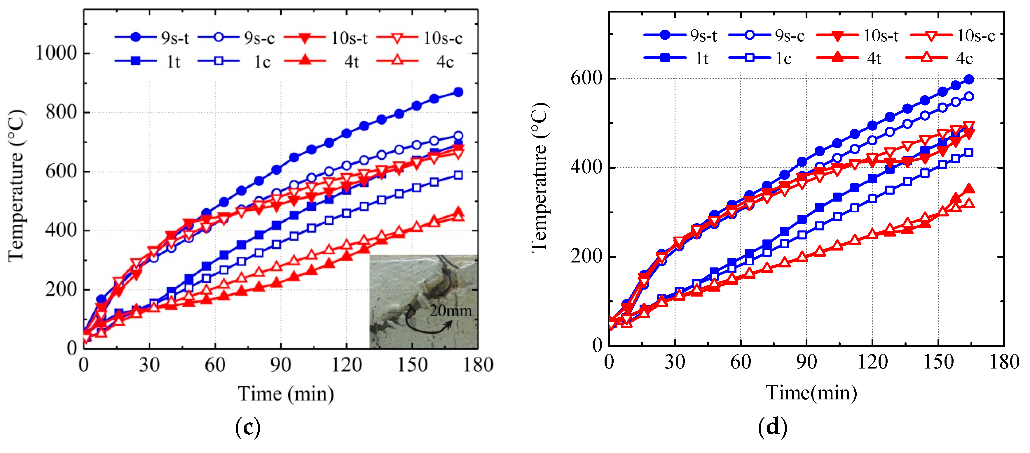
- (a).
- The measured temperatures for Specimen B2 are lower than those for Specimen B4 because the temperature in the furnace chamber is lower for Specimen B2, which is shown in Figure 14.
- (b).
- Referring to Figure 15d, in the later stages of the fire test, the temperatures recorded by Thermocouples 11 and 12 in Specimen B4 are lower than those of Thermocouples 1 and 2 located at the corner and bottom surface of the in-filled concrete. They are close to that of Thermocouple 3 located at the lower part of the side surface of the in-filled concrete and higher than those of Thermocouples 4–6 located at the upper part of the side surface.
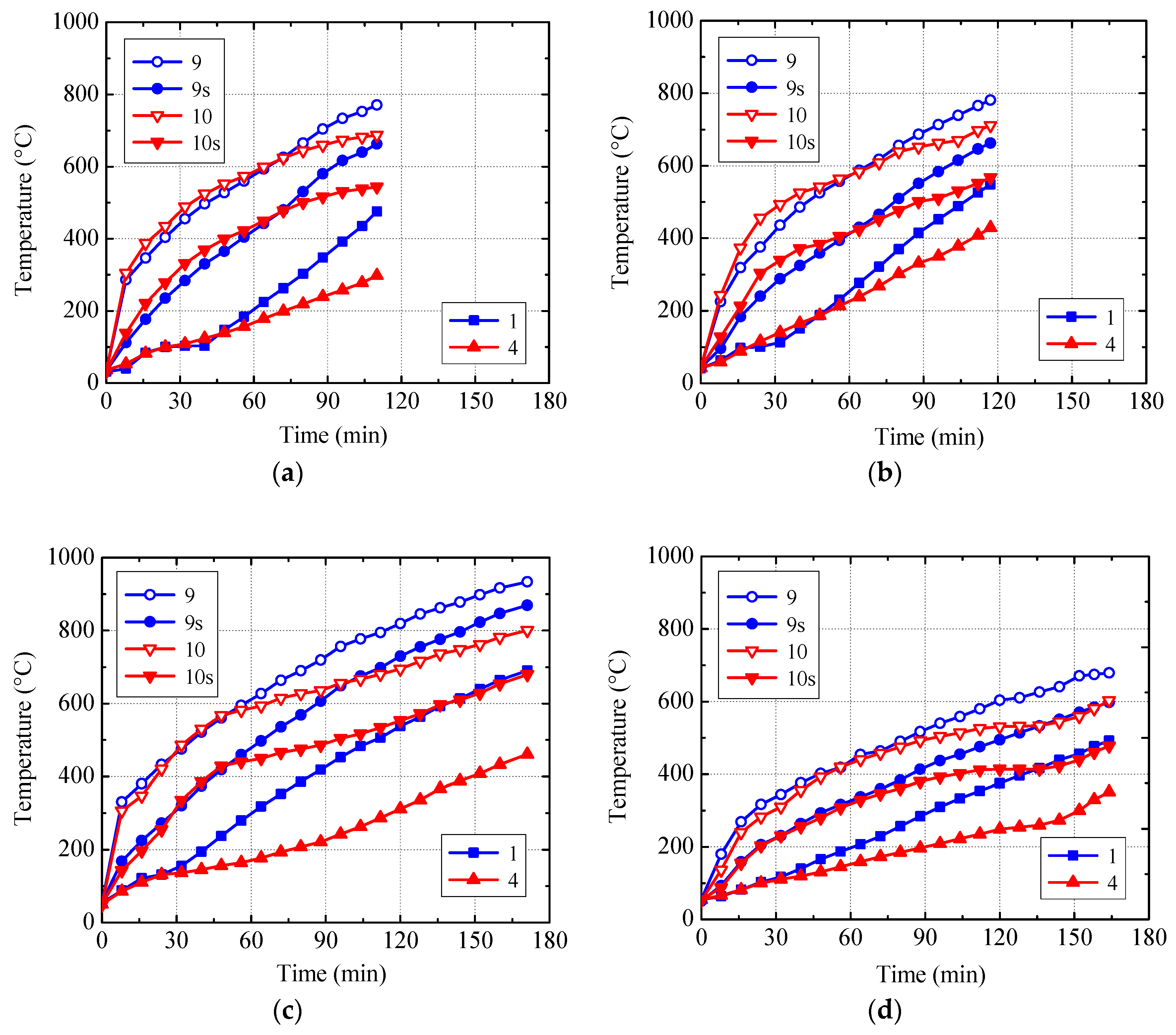
- (a).
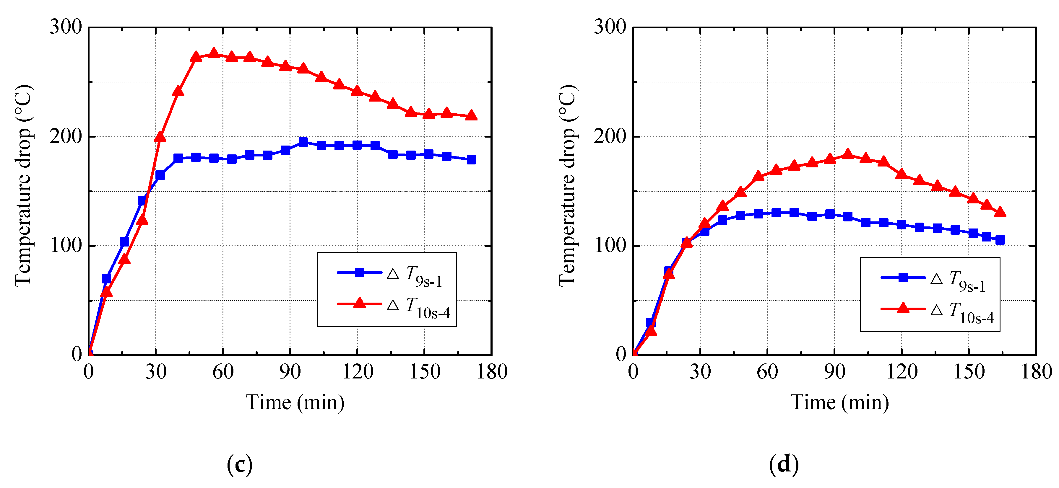
- For Specimen B5, the measured temperatures pertaining to Thermocouples 9 or 10 are, respectively, higher than those related to Thermocouples 9s and 10s and the temperature difference between Thermocouple 9 (or 10) and Thermocouple 9s (or 10s) fluctuates between 80 °C and 125 °C. Therefore, to accurately measure the temperature of steel protected by the fire-retardant coating, the front part of the thermocouple should be perpendicular to the surface of the steel and their end face should be completely in touch with the steel.
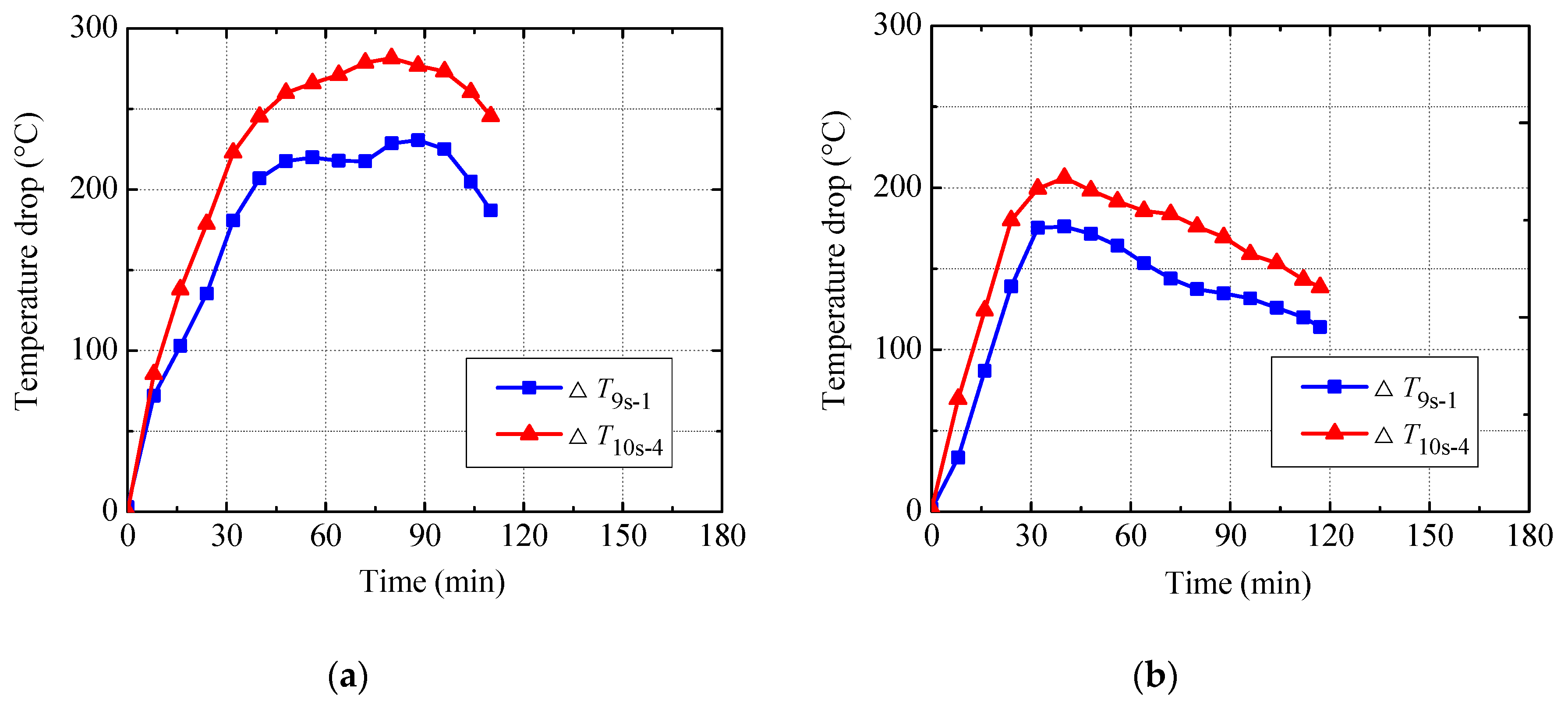
- (b).
- Since the actual thickness of the U-shaped steel is only 2.4 mm and the thermal conductivity of the steel is high, the temperatures recorded by Thermocouples 9s and 10s may be regarded as the temperatures of the inner surface of the steel. So there are remarkable temperature drops (i.e., ∆T9s-1 and ∆T10s-4) at the interface between the U-shaped steel and the in-filled concrete. This may be due to the gap between them induced by the loading and heating. The thermal conductivity of the air and water vapor in the gap is significantly lower than that of the steel and concrete, which impedes the heat flow from the steel to the in-filled concrete to some extent.
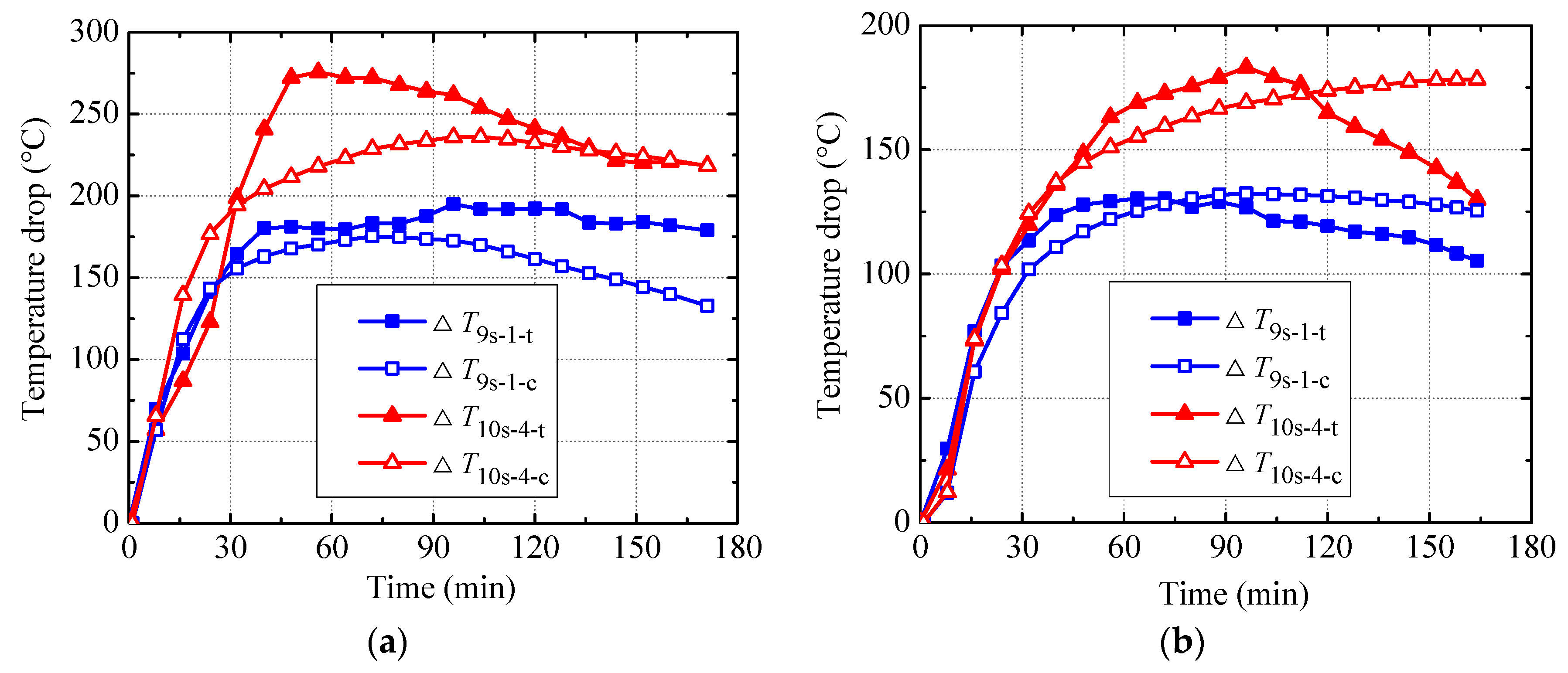
- (c).
- With the increasing of the heating time, the temperature drop at the steel-concrete interface (i.e., ∆T9s-1 and ∆T10s-4) increases at first and then decreases gradually. For Specimens B1, B3, and B4 with a fire insulation thickness of 10 mm, the peak values of ∆T9s-1 vary between 175 °C and 230 °C, and the peak values of ∆T10s-4 range from 205 °C to 280 °C. However, for Specimen B5 with a fire insulation thickness of 18 mm, the peak values of ∆T9s-1 and ∆T10s-4 are, respectively, 130 °C and 183 °C. Clearly, for any given specimen, the peak value of ∆T10s-4 is higher than that of ∆T9s-1, which implies that the thermal resistance at the interface between the U-shaped steel and the in-filled concrete near the mid-height of the beam is greater than that at the bottom. On the other hand, the temperature drop at the steel-concrete interface decreases with increasing the thickness of the fire insulation.
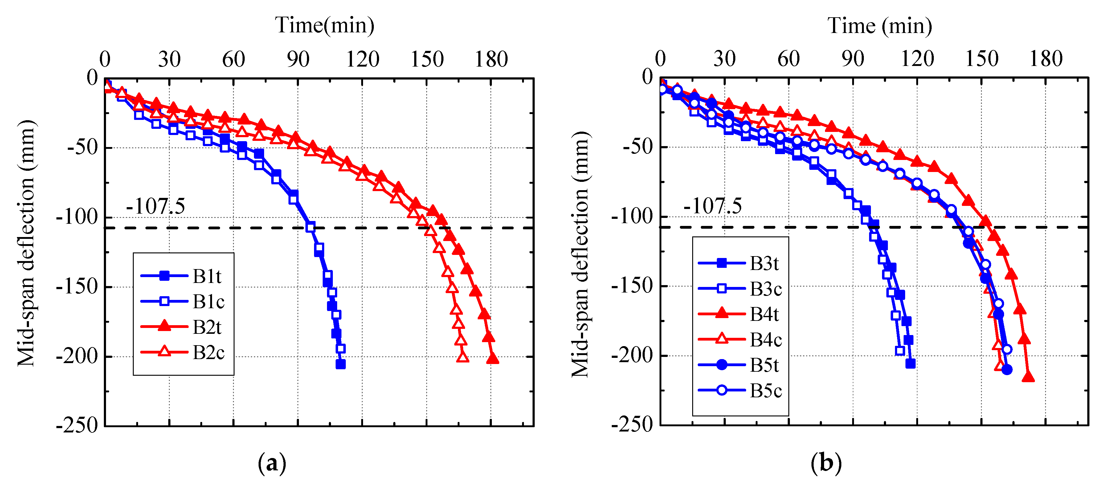
3.3. Structural Response
- (a).
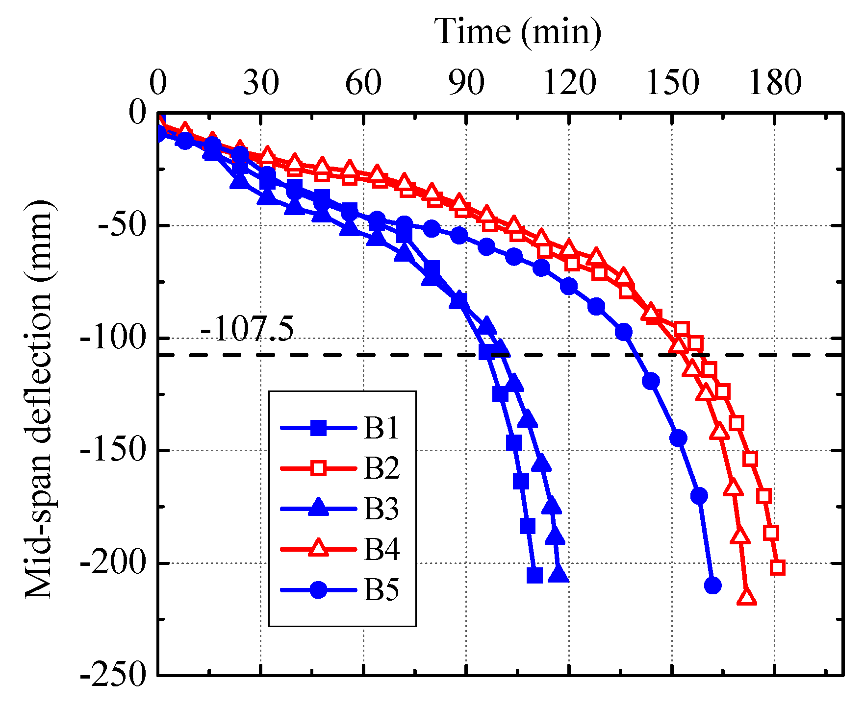
- The measured mid-span deflection-time curves of the specimens with different replacement ratios of DCLs (i.e., Specimens B1 and B3 and Specimens B2 and B4) are close to each other, which implies that using DCLs has almost no influence on the fire-induced deformation.
- (b).
- When the load ratio and the thickness of the fire insulation are the same, the mid-span deflections of the specimens with longitudinal reinforcements (i.e., Specimens B2 and B4) develop much more slowly than those of the specimens without longitudinal reinforcements (i.e., Specimens B1 and B3) because the mechanical properties of the embedded longitudinal reinforcements degrade more slowly than those of the U-shaped steel.
- (c).
- For Specimens B2, B4, and B5 with the same applied load, the development of the mid-span deflections of the former two with longitudinal reinforcements and an insulation thickness of 10 mm is slightly slower than that of the latter one without longitudinal reinforcements and having an insulation thickness of 18 mm.
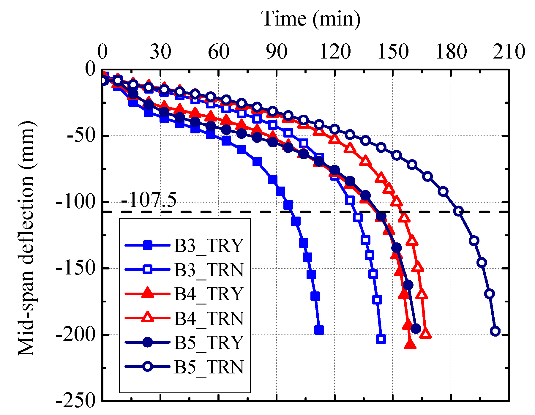
3.4. Fire Resistance
- (a).
- The fire resistance of Specimen B1 (or B2) is very close to that of Specimen B3 (or B4), which indicates that the replacement ratio of DCLs within a range of 0% to 33% has a very limited effect on the fire resistance of the specimens.
- (b).
- With the same load ratio and insulation thickness, the fire resistance of Specimen B2 (or B4) is about 50% longer than that of Specimen B1 (or B3), which implies that embedding longitudinal reinforcements increases the fire resistance significantly.
- (c).
- Although Specimens B2, B4, and B5 were subjected to the same applied load, the former two exhibit longer fire resistance than the latter one, which indicates that embedding longitudinal reinforcements (2φ18) is more effective in improving fire resistance than increasing insulation thickness from 10 mm to 18 mm.
- (d).
- When the actual load ratio is 0.45 and the insulation thickness is 10 mm, the beams without longitudinal reinforcements and with a longitudinal reinforcement ratio of 0.7% can meet the requirements of fire resistance classes R90 and R120, respectively. At the same time, the beam without longitudinal reinforcements and with an insulation thickness of 18 mm can satisfy the requirements of fire resistance class R120 at an actual load ratio of 0.625.
4. Numerical Study
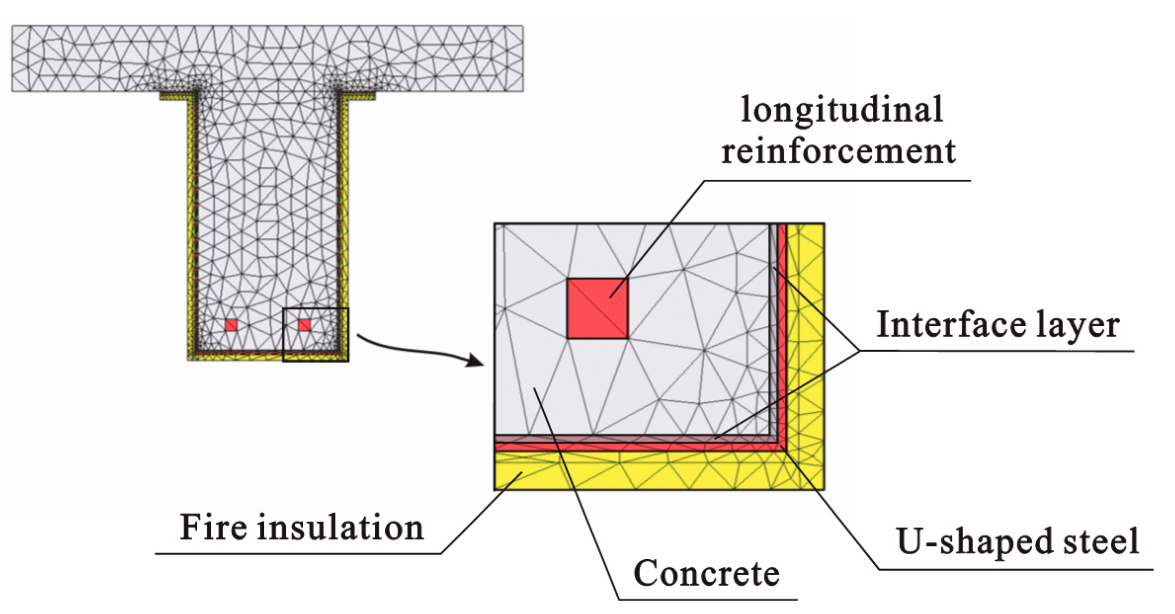
4.1. Finite-Element Models
4.2. Thermal and Mechanical Properties
4.3. Simulation Results and Discussions
4.4. Effect of Interface Thermal Resistance
- (a).
- In the case that the interface thermal resistance is ignored, the temperatures of the U-shaped steel at Points 9s and 10s are lower than those when considering such thermal resistance, whereas the temperatures of the longitudinal reinforcement (Point 11) and the surface of the in-filled concrete (Points 1 and 4) pertaining to the former case are higher than those corresponding to the latter case. This is because more heat can be transferred into the concrete when such thermal resistance is neglected.
- (b).
- In the case that the interface thermal resistance is ignored, the mid-span deflection of the U-shaped steel beam develops more slowly than that when considering such thermal resistance. This is because the temperature of the U-shaped steel is relatively lower in the former case, which makes the mechanical properties of the steel decrease more slowly with heating time. This phenomenon is especially evident for the beams without longitudinal reinforcements (i.e., Specimens B3 and B5) since the increasing of the longitudinal reinforcements’ temperature may partly offset the beneficial effect of the decreasing of the U-shaped steel’ temperature in the former case.
- (c).
- When the interface thermal resistance is ignored, the calculated fire endurances of Specimens B3–B5 are, respectively, 130 minutes, 154 minutes, and 185 minutes, which are 32%, 8%, and 30% longer than the calculated fire endurances of three specimens when considering such thermal resistance, respectively. Clearly, neglecting the interface thermal resistance will greatly overestimate the fire resistance of the U-shaped steel beams filled with DCLs and FC.
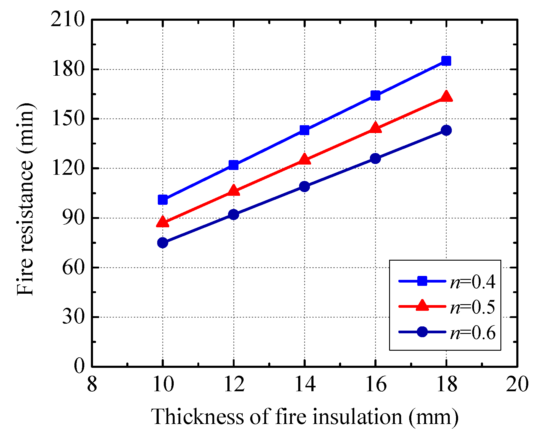
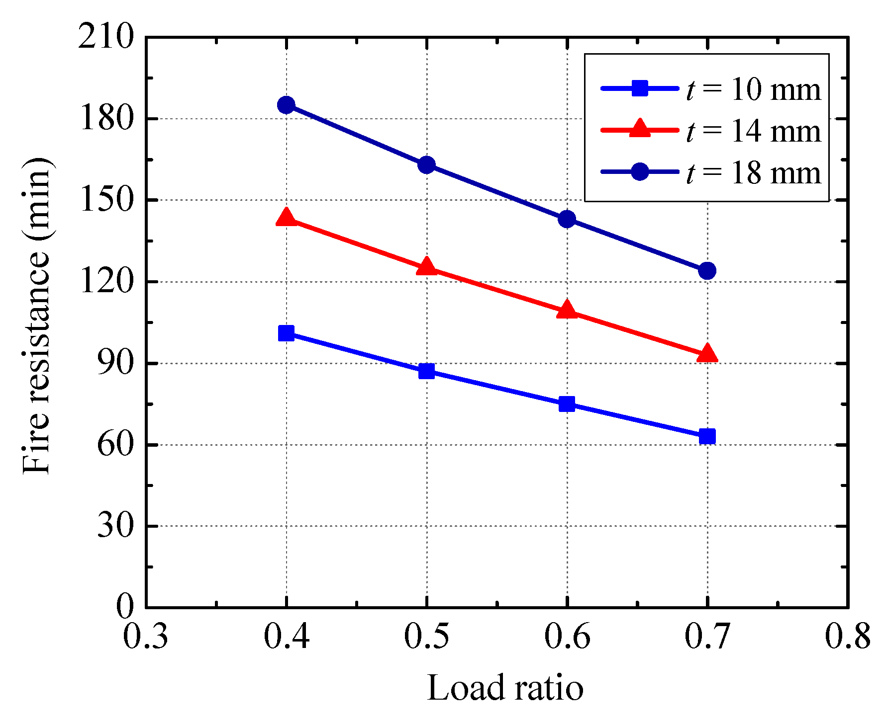
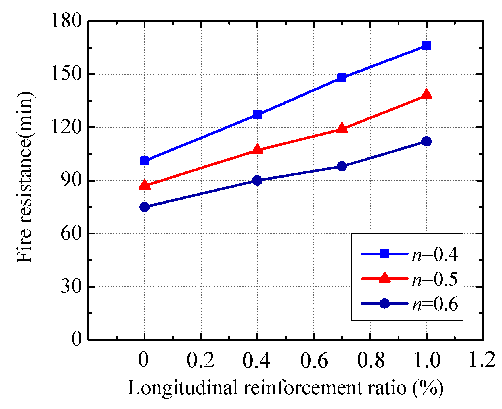
4.5. Parametric Studies
- (a).
- The beam’s fire resistance almost increases linearly with the increasing of the thickness of fire insulation. When the insulation thickness rises from 10 mm to 14 mm (18 mm), the fire endurance enhances by about 43% (87%).
- (b).
- Increasing the load ratio decreases the beam’s fire resistance noticeably. Comparing with the fire endurance related to the load ratio of 0.4, the fire endurances pertaining to the load ratios of 0.5, 0.6, and 0.7 decrease by about 12%, 24% and 35%, respectively.
- (c).
- A significant rise in the beam’s fire resistance can be achieved by increasing the longitudinal reinforcement ratio. For example, at the load ratio of 0.5, raising the longitudinal reinforcement ratio from 0% to 0.4% (0.7%, 1.0%) increases the fire endurance by about 22% (36%, 58%).
5. Conclusions
- (1)
- Fire behavior of the U-shaped steel beam filled with DCLs and FC including failure process, temperature distribution, mid-span deflection, and fire resistance is similar to that of the reference beam filled with FC alone, which implies that using DCLs has a very limited effect on the fire performance.
- (2)
- Satisfactory construction quality can be achieved using the concrete pouring method in this study (i.e., all of the DCLs are put into the U-shaped steel at the same time and then the fresh concrete is poured with a continuous vibration).
- (3)
- The interface thermal resistance between the U-shaped steel and the in-filled concrete near the mid-height of the beam is greater than that at the bottom. The thermal resistance induces a temperature drop of up to 280 °C at the steel-concrete interface. The temperature drop decreases when the thickness of the fire insulation increases.
- (4)
- When the load ratio and the thickness of the fire insulation are the same, the mid-span deflection of the beam with a longitudinal reinforcement ratio of 0.7% develops much more slowly than that of the beam without longitudinal reinforcements and the fire resistance of the former is about 50% longer than that of the latter.
- (5)
- When the actual load ratio is 0.45 and the insulation thickness is 10 mm, the beams without longitudinal reinforcements and with a longitudinal reinforcement ratio of 0.7% can meet the requirements of fire resistance classes R90 and R120, respectively. At the same time, the beam without longitudinal reinforcements and with an insulation thickness of 18 mm can satisfy the requirements of fire resistance class R120 at an actual load ratio of 0.625.
- (6)
- Neglecting the interface thermal resistance between the U-shaped steel and the in-filled concrete will greatly overestimate the fire resistance of the beams. The thermal resistance at the interface between the web of the U-shaped steel and the in-filled concrete is suggested to be 0.03 m2 K/W and at the interface between the bottom flange of the U-shaped steel and the in-filled concrete is recommended to be 0.02 m2 K/W.
Author Contributions
Acknowledgments
Conflicts of Interest
References
- Oikonomou, N.D. Recycled concrete aggregates. Cem. Concr. Compos. 2005, 27, 315–318. [Google Scholar] [CrossRef]
- Topçu, I.B. Physical and mechanical properties of concretes produced with waste concrete. Cem. Concr. Res. 1997, 27, 1817–1823. [Google Scholar] [CrossRef]
- Shayan, A. Performance and Properties of Structural Concrete Made with Recycled Concrete Aggregate. ACI Mater. J. 2003, 100, 371–380. [Google Scholar]
- Bravo, M.; Brito, J.D.; Evangelista, L. Thermal performance of concrete with recycled aggregates from CDW plants. Appl. Sci. 2017, 7, 740. [Google Scholar] [CrossRef]
- Thomas, C.; Setién, J.; Polanco, J.A.; Alaejos, P.; Juan, M.S.D. Durability of recycled aggregate concrete. Constr. Build. Mater. 2013, 40, 1054–1065. [Google Scholar] [CrossRef]
- Mohamad, N.; Khalifa, H.; Samad, A.A.A.; Mendis, P.; Goh, W.I. Structural performance of recycled aggregate in CSP slab subjected to flexure load. Constr. Build. Mater. 2016, 115, 669–680. [Google Scholar] [CrossRef]
- Kang, H.K.; Kim, W.; Kwak, Y.K.; Hong, S.G. Flexural testing of reinforced concrete beams with recycled concrete aggregates. ACI Struct. J. 2014, 111, 607–616. [Google Scholar] [CrossRef]
- Fathifazl, G.; Razaqpur, A.G.; Isgor, O.B.; Abbas, A.; Fournier, B.; Foo, S. Shear strength of reinforced recycled concrete beams with stirrups. Mag. Concr. Res. 2009, 61, 477–490. [Google Scholar] [CrossRef]
- Choi, W.C.; Yun, H.D. Compressive behavior of reinforced concrete columns with recycled aggregate under uniaxial loading. Eng. Struct. 2012, 41, 285–293. [Google Scholar] [CrossRef]
- Liu, W.C.; Cao, W.L.; Zong, N.N.; Wang, R.W.; Ren, L.L. Experimental study on punching performance of recycled aggregate concrete thin wallboard with single-layer reinforcement. Appl. Sci. 2018, 8, 188. [Google Scholar] [CrossRef]
- Xiao, J.; Sun, Y.; Falkner, H. Seismic performance of frame structures with recycled aggregate concrete. Eng. Struct. 2006, 28, 1–8. [Google Scholar] [CrossRef]
- RILEM TC 121-DRG. Specification for concrete with recycled aggregates. Mater. Struct. 1994, 27, 557–559. [CrossRef]
- ACI Committee 555. Removal and Reuse of Hardened Concrete; ACI 555R-01; American Concrete Institute: Farmington Hills, MI, USA, 2001. [Google Scholar]
- Ministry of Housing and Urban-Rural Development of the People’s Republic of China. Technical Specification for Application of Recycled Aggregate; JGJ/T 240-2011; China Architecture & Building Press: Beijing, China, 2011.
- Wu, B.; Xu, Z.; Ma, Z.J.; Liu, Q.X.; Liu, W. Behavior of reinforced concrete beams filled with demolished concrete lumps. Struct. Eng. Mech. 2011, 40, 411–429. [Google Scholar] [CrossRef]
- Wu, B.; Liu, C.H.; Yang, Y. Size effect on compressive behaviours of normal-strength concrete cubes made from demolished concrete blocks and fresh concrete. Mag. Concr. Res. 2013, 65, 1155–1167. [Google Scholar] [CrossRef]
- Zhao, X.Y.; Wu, B.; Wang, L. Structural response of thin-walled circular steel tubular columns filled with demolished concrete lumps and fresh concrete. Constr. Build. Mater. 2016, 129, 216–242. [Google Scholar] [CrossRef]
- Wu, B.; Zhao, X.Y.; Zhang, J.S. Cyclic behavior of thin-walled square steel tubular columns filled with demolished concrete lumps and fresh concrete. J. Constr. Steel Res. 2012, 77, 69–81. [Google Scholar] [CrossRef]
- Wu, B.; Ji, M.M. Flexural tests on thin-walled U-shaped steel beams filled with demolished concrete blocks and fresh concrete. J. Build. Struct. 2014, 35, 246–254. (In Chinese) [Google Scholar]
- Wu, B.; Liu, C.H.; Liu, Q.X. Tests on seismic behaviors of double thin skin hybrid walls filled with demolished concrete lumps. Key Eng. Mater. 2012, 517, 536–545. [Google Scholar] [CrossRef]
- Wu, B.; Luo, Z.C. Mechanical property of composite slabs with profiled steel sheet casted using demolished concrete blocks and fresh concrete. J. Build. Struct. 2016, 37, 29–38. (In Chinese) [Google Scholar]
- Wu, B.; Duan, J.; Wen, B. Preparations of new fireproof coating and fire-resistance tests on composite slabs filled with demolished concrete blocks and fresh concrete. China Civ. Eng. J. 2014, 47, 82–92. (In Chinese) [Google Scholar]
- Teng, J.G.; Zhao, J.L.; Yu, T.; Li, L.J.; Guo, Y.C. Behavior of FRP-confined compound concrete containing recycled concrete lumps. J. Compos. Constr. 2016, 20, 1–13. [Google Scholar] [CrossRef]
- Wu, B.; Ji, M.M.; Zhao, X.Y. State-of-the-art of recycled mixed concrete (RMC) and composite structural members made of RMC. Eng. Mech. 2016, 33, 1–10. (In Chinese) [Google Scholar]
- Wu, B.; Yu, Y.; Chen, Z. Compressive Behaviors of Prisms Made of Demolished Concrete Lumps and Fresh Concrete. Appl. Sci. 2018, 8, 743. [Google Scholar] [CrossRef]
- Ding, J.; Wang, Y.C. Realistic modelling of thermal and structural behaviour of unprotected concrete filled tubular columns in fire. J. Constr. Steel Res. 2008, 64, 1086–1102. [Google Scholar] [CrossRef]
- Tao, Z.; Ghannam, M. Heat transfer in concrete-filled carbon and stainless steel tubes exposed to fire. Fire Saf. J. 2013, 61, 1–11. [Google Scholar] [CrossRef]
- Ministry of Housing and Urban-Rural Development of the People’s Republic of China. Technical Specification for Testing Concrete Strength with Drilled Core Method; JGJ/T 384-2016; China Architecture & Building Press: Beijing, China, 2016.
- ISO/TC 92/SC 2. In Fire-Resistance Tests—Elements of Building Construction—Part 1: General Requirements; ISO 834-1:1999; International Organization for Standardization: Geneva, Switzerland, 1999.
- Franssen, J.M. SAFIR: A thermal/structural program for modeling structures under fire. Eng. J. 2005, 42, 143–158. [Google Scholar]
- Franssen, J.M.; Gernay, T. User’s Manual for SAFIR 2016c: A Computer Program for Analysis of Structures Subjected to Fire; University of Liege: Liege, Belgium, 2016. [Google Scholar]
- Kruppa, J.; Zhao, B. Fire Resistance of Composite Beams to Eurocode 4 Part 1.2. J. Constr. Steel Res. 1995, 33, 51–69. [Google Scholar] [CrossRef]
- Sanad, A.M.; Rotter, J.M.; Usmani, A.S.; O’Connor, M.A. Composite beams in large buildings under fire—Numerical modelling and structural behaviour. Fire Saf. J. 2000, 35, 165–188. [Google Scholar] [CrossRef]
- Fike, R.; Kodur, V. Enhancing the fire resistance of composite floor assemblies through the use of steel fiber reinforced concrete. Eng. Struct. 2011, 33, 2870–2878. [Google Scholar] [CrossRef]
- Patel, V.I.; Liang, Q.Q.; Hadi, M.N.S. Nonlinear analysis of axially loaded circular concrete-filled stainless steel tubular short columns. J. Constr. Steel Res. 2014, 101, 9–18. [Google Scholar] [CrossRef] [Green Version]
- Kodur, V.K.R.; Naser, M.; Pakala, P.; Varma, A. Modeling the response of composite beam-slab assemblies exposed to fire. J. Constr. Steel Res. 2013, 80, 163–173. [Google Scholar] [CrossRef]
- Naser, M.; Kodur, V. Response of fire exposed composite girders under dominant flexural and shear loading. J. Struct. Fire Eng. 2018, 9, 108–125. [Google Scholar] [CrossRef]
- European Committee for Standardization. Eurocode 4: Design of Composite Steel and Concrete Structures—Part 1–2: General Rules—Structural Fire Design; BS EN 1994-1-2:2005; British Standards Institution: London, UK, 2005. [Google Scholar]
- European Committee for Standardization. Eurocode 2: Design of Concrete Structures—Part 1–2: General Rules—Structural Fire Design; BS EN 1992-1-2:2004; British Standards Institution: London, UK, 2005. [Google Scholar]
- China Association for Engineering Construction Standardization. Regulation of Application Technology of Fire Resistive Coating for Steel Structures; CECS24:90; Chinese Planning Press: Beijing, China, 1991. [Google Scholar]
- Yang, S.M.; Tao, W.S. Heat Transfer; Higher Education Press: Beijing, China, 2006. [Google Scholar]
- Dwaikat, M.M.S.; Kodur, V.K.R. A simplified approach for predicting temperatures in fire exposed steel members. Fire Saf. J. 2013, 55, 87–96. [Google Scholar] [CrossRef]
- Ghojel, J. Experimental and analytical technique for estimating interface thermal conductance in composite structural elements under simulated fire conditions. Exp. Therm. Fluid Sci. 2004, 28, 347–354. [Google Scholar] [CrossRef]


| Specimen | η | Longitudinal Reinforcements (ρs) | fyr (MPa) | fy (MPa) | fcu, new (MPa) | fcu, old (MPa) | N (kN) | n | t (mm) | R (min) |
|---|---|---|---|---|---|---|---|---|---|---|
| B1 | 0 | – | – | 305 | 40.6 | 36.5 | 140.5 | 0.45 | 10 | 98 |
| B2 | 0 | 2φ18 (0.7%) | 414.5 | 203.5 | 0.45 | 10 | 158 | |||
| B3 | 33% | – | – | 140.5 | 0.45 | 10 | 102 | |||
| B4 | 33% | 2φ18 (0.7%) | 414.5 | 203.5 | 0.45 | 10 | 154 | |||
| B5 | 33% | – | – | 203.5 | 0.625 | 18 | 140 |
| Concrete | Water | Cement | Fine Aggregate | Coarse Aggregate | Fly Ash | Water Reducer |
|---|---|---|---|---|---|---|
| Fresh concrete | 195 | 410 | 658 | 1078 | 75 | 5 |
| Demolished concrete | 180 | 356 | 708 | 1133 | 50 | 3 |
© 2018 by the authors. Licensee MDPI, Basel, Switzerland. This article is an open access article distributed under the terms and conditions of the Creative Commons Attribution (CC BY) license (http://creativecommons.org/licenses/by/4.0/).
Share and Cite
Wu, B.; Ji, M. Fire Behavior of U-shaped Steel Beams Filled with Demolished Concrete Lumps and Fresh Concrete. Appl. Sci. 2018, 8, 1361. https://doi.org/10.3390/app8081361
Wu B, Ji M. Fire Behavior of U-shaped Steel Beams Filled with Demolished Concrete Lumps and Fresh Concrete. Applied Sciences. 2018; 8(8):1361. https://doi.org/10.3390/app8081361
Chicago/Turabian StyleWu, Bo, and Mingming Ji. 2018. "Fire Behavior of U-shaped Steel Beams Filled with Demolished Concrete Lumps and Fresh Concrete" Applied Sciences 8, no. 8: 1361. https://doi.org/10.3390/app8081361