Article

Rapid Prototyping of Multi-Functional Battery Energy Storage System Applications

by
Claudia Zanabria
1,*,
Filip Pröstl Andrén
1,
Johannes Kathan
1 and
Thomas I. Strasser
1,2
1
Center for Energy–Electric Energy Systems, AIT Austrian Institute of Technology, 1210 Vienna, Austria
2
Institute of Mechanics and Mechatronics, Vienna University of Technology, 1040 Vienna, Austria
*
Author to whom correspondence should be addressed.
Appl. Sci. 2018, 8(8), 1326; https://doi.org/10.3390/app8081326
Submission received: 18 July 2018 / Revised: 2 August 2018 / Accepted: 4 August 2018 / Published: 8 August 2018

Abstract

:
Battery Energy Storage Systems (BESS) are starting to play an important role in today’s power distribution networks. They provide a manifold of services for fulfilling demands and requests from diverse stakeholders, such as distribution system operators, energy market operators, aggregators but also end-users. Such services are usually provided by corresponding Energy Management Systems (EMS). This paper analyzes the complexity of the EMS development process resulting from an evolving power utility automation. As a result, flexibility, complexity, interoperability, and overlapping issues were identified as main concerns to be faced during the design and implementation stages of BESS control applications. Current efforts from smart grid and power utility automation standards partially tackle the issues mentioned above. Nevertheless, an integrated methodology that guides and supports control engineers during the whole development chain is still missing. Hence, the conception of EMSOnto is introduced. The main achievements of this approach include the alignment of BESS design with broadly accepted smart grid standards (i.e., IEC 61850, smart grid architecture model), a common understanding of EMS control applications based on the conception of an ontology, the identification of conflicts within a multi-function BESS and the semi-automatic generation of software artifacts mainly important for EMS validation. To demonstrate the effectiveness of the approach, a selected use case example is designed and validated in a hardware-in-the-loop basis. This proves that EMSOnto eases the work of control engineers resulting in a flexible, adaptable, and error-free EMS design. In addition to this, limitations of EMSOnto as well as future work are grasped.

1. Introduction

The reduction of greenhouse gas emissions motivates a high penetration of renewable Distributed Energy Resources (DERs). However, this may negatively influence the power quality (i.e., frequency and voltage) and surpass the hosting capacity of the corresponding power distribution grids. Battery Energy Storage Systems (BESS) are becoming an important actor in the power utility grid due to their flexibility and support that they offer. Use Cases (UCs) based on BESS participation are considered in different studies [1,2], attempting to contribute to voltage and frequency regulation. Other services such as improvement of the hosting capacity and peak-shaving are also possible [3]. Additionally, BESS supports Energy Market Operators (EMO) to benefit from the spot market prices [4] and the end-user to minimize their energy costs [5]. The implementation of the mentioned UCs implies an efficient use of the Information and Communication Technology (ICT) infrastructure and the integration between various stakeholders and DERs.
Energy Management Systems (EMS) carry out the integration of BESS UCs. Thus, they require to reach a high degree of flexibility and adaptability. Furthermore, their design becomes quite complex since different power utility equipment and stakeholders are involved. Additionally, due to the offering of many services, a coordination and alignment of control strategies is required. Those issues among others are faced during the development process of EMS. Motivating the conception of a common vocabulary to be approved by different control engineers dedicated to EMS implementation.
Existent approaches support control engineers during the engineering process; Systems Modeling Language (SysML) and Smart Grid Architecture Model (SGAM) are highly recommended at the specification stage [6]. Power System Automation Language (PSAL), a Domain Specific Language (DSL) for power systems, automates the design and implementation of smart grid applications [7]. Besides this, a power utility automation standard called IEC 61850 models DERs functionalities [8]. The implementation of them is driven by automation standards such as IEC 61499 [9] and IEC 61131-3 [10]. On this basis, this paper analyzes current smart grid and automation approaches and points out the lack of an integrated framework and methodology that guides control engineers during the design and implementation phase of EMS applications. As a solution, this paper proposes EMSOnto, a framework focused on interoperability, flexibility, complexity, and overlapping issues raised during BESS UCs implementation. Current efforts to handle those issues are evaluated, hence a set of four requirements are identified which provides the basis for the EMSOnto conception.
The core part of the EMSOnto approach is an ontology (i.e., EMS-ontology) that models different aspects of a multi-functional BESS such as potential conflicts between UCs, variables exchanged across the EMS communication architecture, structure of control strategies, etc. This modeling process is aligned with domain-specific approaches like IEC 61850 and SGAM. PSAL proposes a data model for power systems also based on SGAM and IEC 61850, but concepts for the abstraction of BESS services were not tackled. A main benefit of ontologies is to infer new knowledge from explicit knowledge. This benefit is key in the identification of conflicts, a feature supported by EMSOnto and not contemplated by any of the previous mentioned approaches. In addition to this, a friendly method to gather information from control engineers based on spreadsheet templates (i.e., EMS-templates) is exposed. This mechanism enables the population of the EMS-ontology. IntelliGrid enables the gathering of data by UC templates, however they are not suitable for collection of static and dynamic variables presented in an EMS. On the other hand, Model-Driven Engineering (MDE) is employed to semi-automatically generate software artifacts to be deployed in power system and automation tools. The rapid prototyping of smart grid applications by means of MDE techniques is not a completely new topic since it was already tackled by PSAL and other works [11]; however, the benefits of an automatic generation of software artifacts for the proof-of-concept of BESS applications is not yet addressed.
This paper is structured as follows: Section 2 presents UCs mainly important to BESS support, their corresponding development process are analyzed resulting in the identification of issues to be target by EMSOnto. Section 3 addresses those issues by analyzing current efforts carried out to handle them. From this evaluation, gaps and open issues are identified resulting in the statement of four requirements to design EMSOnto. Section 4 presents the core of EMSOnto, an ontology mainly designed to meet specific requirements. Additionally, a friendly method to populate the ontology is addressed by spreadsheet templates. As a sequel, Section 5 designs and implements a selected UC following the EMSOnto basis. This enables the identification of gaps and guidelines to improve EMSOnto. Finally, Section 6 summarizes and concludes this work.

2. Multi-Functional Energy Storage System Application Development

This section presents a list of selected UCs that address demands from various stakeholders. A correct operation of those UCs requires the follow up of an engineering process. This involves specification, design, implementation, and realization stages. Furthermore, the whole development chain of an EMS realization is also exposed. In that context, important issues to facilitate the control engineer’s work and also to reach a flexible and interoperable EMS are raised.

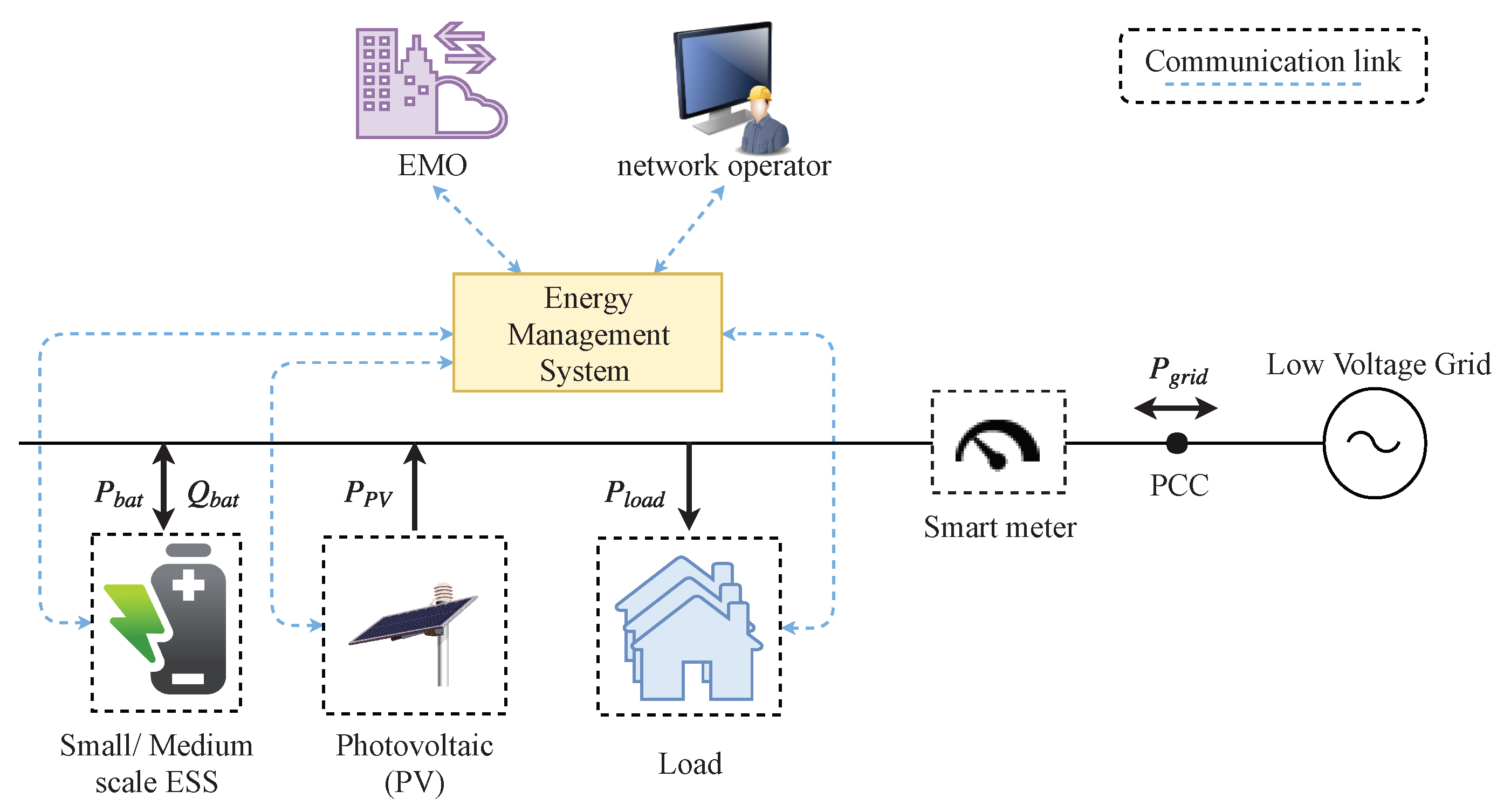
2.1. Use Cases and Applications

The selection of use cases UC1–UC5 is based on common services provided mainly by small scale energy storage systems (∼ > 3.6 kW & < 4.8 kW), see Table 1. An extended list can be found in the study [4] where a categorization by objectives, such as reduction of energy costs, power system stability, and market integration is carried out. A scheme that represents electrical devices connection and communication links, in the frame of those UC, is depicted in Figure 1. A BESS is integrated within the low-voltage grid to mainly support the user to minimize energy costs. This is reached by storing the Photovoltaic (PV) generated energy not consumed by the local load. This mechanism corresponds to UC3 where the customer is the main benefactor. However, those batteries are able to provide support to the grid operator for power system stability purposes. Thus, not only self-consumption (UC3) is pursued but other services such as voltage and frequency regulation (UC1-UC2). Following that premise, the study [5] is also selected (UC4); it defines a multi-functional system embedded with peak-shaving and reduction of price services. An ensemble of storage services is also met by UC5 [1]. That case study gathers voltage control and two other services, it is an appealing example since each service rents one part of the whole capacity of a medium scale BESS. At first glance, it might seem that services do not need to be aligned because of the capacity allocation procedure. However, study [1] analyzes conflict issues regarding a full provision of those services. Since conflict identification is a main requirement to be covered by the EMS-ontology, UC5 is included in the selection of UCs.

2.2. Specification and Development Process

The realization of EMS control applications requires following certain stages, which involves specification, design, proof-of-concept, implementation, and deployment [14]. Those steps are addressed in this section.
At the specification stage, the stakeholders, DERs, and Intelligent Electronic Devices (IEDs), involved in the system under study, are identified. In addition to this, the communication and physical architecture are suggested. This results in a list of requirements to be addressed during the design phase. Subsequently, at the design level, solutions to define the specific behavior and structure of control strategies embedded by an EMS are evaluated. Hence, a list of variables encompassing control, setpoint and measurement signals are properly described. This description also gathers information related to protocols communication. Thus, the communication interfaces that allow interconnection across the power distribution application are also specified. Furthermore, the allocation of control strategies through the ICT hardware infrastructure is determined as well.
The validation of the proposed control strategies is carried out at the proof-of-concept phase. At that stage, models of IEDs (e.g., smart meters) and DERs (e.g., BESS) are built and deployed into a power system emulator (e.g., MATLAB/Simulink, DlgSILENT PowerFactory), along with the control logic of the EMS [15]. The transition from design to proof-of-concept may entail communication and stability issues that were not considered at the design stage. Hence, an iterative refinement of the control algorithms are considered. Afterwards, the deployment of the validated control algorithms takes place at the implementation phase. A programming language compatible with a specific hardware controller is chosen to deploy the logic, usually this is driven by automation standards such as IEC 61499 [9] and IEC 61131-3 [10]. The validation of implementation phase is carried out by real-time simulations, controller-hardware-in-the-loop, and/or laboratory-based tests [16].

2.3. Open Issues

A closer analysis of the abovementioned design and engineering process results in the following issues which need to be addressed:
  • Flexibility: The integration of new and different actors into the power distribution grid such as Electrical Vehicles (EV) and EMO motivates evolving services focused on BESS participation. Thus, EMS should be flexible enough to implement those services and future ICT requirements.
  • Complexity: The complex-nature of EMS is based on the manifold of services provided by BESS and the deployment of them in the ICT and power system infrastructure. The implementation of such services may be centralized or decentralized. In case of a decentralized configuration, where services are deployed in different hardware controllers, more than one control engineer may be required for the EMS design. Thereby, the lack of a common vocabulary and design language may lead to errors during EMS design and later on operation in the field.
  • Overlapping: An EMS focused on multi-services for BESS is vulnerable to conflicts between UCs. This overlapping across them could cause a non-expected function behavior. For instance, an EMS that operates UC2 and UC3 would need to setup mechanisms to align both use cases in the event of a simultaneous operation. Otherwise, those UCs would not be attained.
  • Interoperability: The realization and validation of smart grid and BESS-based applications entails the use of a wide range of power system, automation and communication tools. This goes from power system emulators/design, network simulators to co-simulation frameworks. However, a method to interoperate those tools during the whole chain of the engineering process is missing.

3. Related Work and Background

Issues which need to be tackled during the engineering process were previously highlighted. In this section, the state-of-the-art and related work are analyzed and discussed. Necessary requirements for improving the status-quo are identified, which provide cornerstones for the rapid development of UCs and applications.

3.1. Smart Grid Domain Standards

The main concern of the current study is to employ information models from recommended international standards to derive an interoperable and flexible solution. Data models for the power system domain are outlined in the IEC Smart Grid Standardization Roadmap [17]. On this basis, a collection of standards mainly important to DER involved in BESS UCs has been gathered, resulting in the following list:
  • IEC 61970/IEC 61968 Common Information Model (CIM): Its main concern is to ensure interoperability across power networks, [18]. Thereby, it offers a common semantic for EMS, Supervisory and Control Data Acquisition (SCADA) and power system topology. This is formally represented by a Unified Modeling Language (UML) model, including over 1300 classes.
  • IEC 61850: It is mainly conceived to improve interoperability between IEDs in a power system substation; nowadays, it has been extended to DERs and power utility components among other areas [8]. Functional aspects of an IED are mapped into a Logical Node (LN). They are referenced in the standard IEC 61850-7-4 and extended by IEC 61850-7-420 [19], where functionalities of DERs such as inverters and batteries are modeled.
  • IEC 62325: It provides a set of standards related to market communication using CIM, covering data models for market participants and market operators.
  • IEC 62056: It applies mainly to smart home and data exchange for meter reading.
  • Open Platform Communications Unified Architecture (OPC UA): Since the EMS should support the exchange with other IEDs distributed along the power utility grid, the consideration of information models from the automation domain such as OPC UA is relevant. It is a standard of OPC foundation that focuses on exchanging real-time data within the process automation. It is platform-independent, thereby not tied to one operating system. It is standardized under IEC 62541, part 5 of that standard defines the information model (IEC 62541-5) [20].

3.2. Smart Grid Control Application Development Approaches

The development of smart grid control applications has been supported by a collection of approaches. Those are characterized by domain standards (SGAM, CIM, UML, etc.), well recognized tools (MATLAB/Simulink, etc.) and frameworks (PSAL, etc.). A comparison that measures the applicability of them through the design, proof-of-concept and implementation phase is carried out in this section. A brief introduction to the approaches is firstly described below:
  • Unified Modeling Language: UML is a general-purpose language for an object-oriented software development [21]. It has been standardized by the Object Management Group (OMG) and approved as an ISO standard. UML specifies behavior and structural diagrams to model software applications. Thereby, it has been used in the power system domain to model use cases [22].
  • System Modeling Language (SysML): SysML is conceived as an extension of a subset of UML. It is mainly designed to support the system engineering process (i.e., specification, design). Thereby, elements in UML not required by systems engineering were excluded to conceive SysML [21].
  • IntelliGrid (IEC 62559): Intelligrid introduces a methodology to document and detail smart grid UCs. From this, a UC template [23] that covers best practices to describe requirements engineering is originated. In those templates, a UC may be described by a visual representation (e.g., UML diagram). IEC 62559 is largely accepted by the power system community as an example the adoption of it by the ELECTRA project [22].
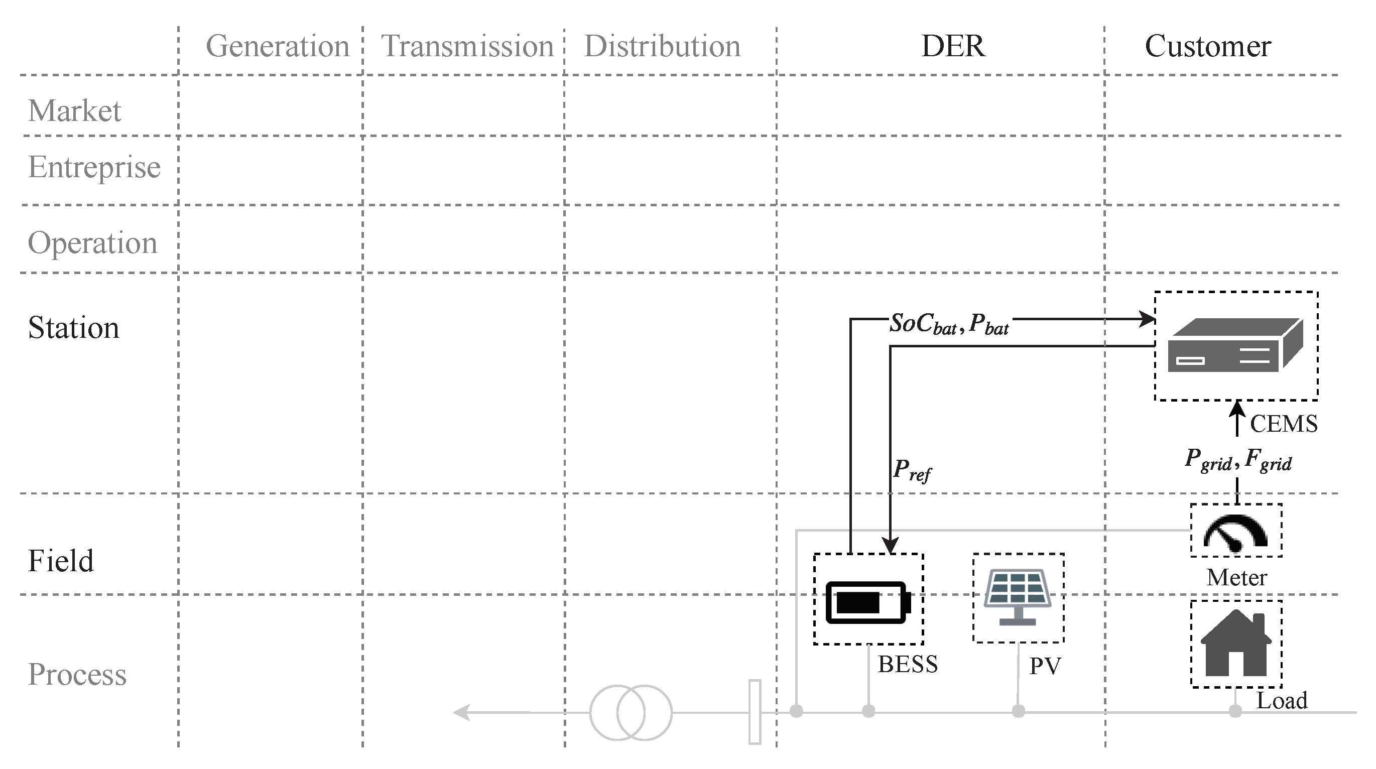
  • Smart Grid Architecture Model: SGAM is introduced by the SG-CG/RA (Smart Grid Coordination Group/Reference Architecture) [24]. SGAM is conceived to model smart grid uses cases architecture in a technology-neutral manner. It consists of five interoperability layers, those layers are matched to a smart grid plane composed of domains and zones. The domains cover the electricity conversion chain (i.e., transmission, distribution, etc.). The zones cover the automation pyramid (i.e., process, field, etc.). An implementation of SGAM is conceived in [25] as a plugin of the Sparx Systems Enterprise Architecture tool, it is called SGAM-Toolbox (SGAM-TB).
  • Power System Automation Language: PSAL is a DSL to model SGAM compatible use case specifications. It supports control engineers during the whole development process, from use case design to implementation and deployment. In addition to this, PSAL offers executable code and communication configuration file generation [7].
  • MATLAB/Simulink: This tool provides libraries to model and simulate electrical power systems. C-code generation is also contemplated for a rapid prototyping of MATLAB/Simulink models. Since this tool is largely accepted and employed in the power system domain, it is considered as a worthy approach to be analyzed along the control application development process.
  • IEC 61499: This approach provides a reference model for Distributed Control Systems (DCS) in the domain of industrial processes. A main objective is to reach portability, configurability and interoperability across DCSs [9].
  • IEC 61131-3: IEC 61131 is an IEC standard supported by Programmable Logic Controller (PLC). One of the main goals of IEC 61131 is to standardize the programming approaches. Thus, the part IEC 61131-3 offers graphical and textual programming languages such as function block diagram and structured text among others [10].
A comparison of the aforementioned approaches is outlined in [6], covering mainly specification and design stages. A brief discussion of features analyzed at the design stage is addressed in the following. At the function level, data models for UCs and graphical representations to detail the structure and behavior of control applications are considered. Semantic data models of information within control applications and DERs devices are evaluated at the information level. In turn, mechanisms for representing communication architectures and the allocation of logical components across hardware devices are assessed at the communication and component level.
The referred comparison study highlights that, in the specification phase, the outstanding approaches are SysML and SGAM; however, they are not recommended at the design phase. In turn, PSAL is recommended at the design stage. Nevertheless, the referred study does not consider overlapping and complexity issues important to a multi-functional BESS implementation. Those issues are addressed in the present study resulting in Table 2. This analysis demonstrates that there is no preferable candidate that covers function and information domain at the design phase.
Execution of control strategies (i.e., function domain) at the proof-of-concept and implementation stages are well supported by IEC 61499, IEC 61131-3 and MATLAB/Simulink. Rapid prototyping is a feature not well-exploited by all the approaches and only PSAL and MATLAB address it. In this context, MATLAB proposes generation of C-code from Simulink models and PSAL generates control applications compliant with IEC 61499.

3.3. Ontologies for Smart Grid Applications

Ontologies search for a formal representation and categorization of information abstracted from real systems. This is achieved by referencing the components: classes, individuals, relations, attributes, rules, etc. [26]. The main advantage of ontologies is the inference of new knowledge from explicit knowledge by the execution of reasoning mechanisms. The most well known ontology language is Ontology Web Language (OWL), a key benefit offered is the expression of complex knowledge in a machine-readable form. Moreover, due to OWL being based on description logics (DL), an expressive formal knowledge representation is obtained.
DL give mechanisms to describe accurately ontologies by introducing the terminological ( T B o x ) and assertional ( A B o x ) component [27]. The T B o x contains sentences describing concepts and relation between concepts. Instantiation of those concepts are carried out by the A B o x . For instance, the statement: an EMS embeds more than one service, belongs to the T B o x , and the concepts identified are EMS and service. In turn, the sentence: frequency-watt mode is a service belongs to the A B o x , where the individual frequency-watt is an instance of the concept service.
A mechanism to enhance the reasoning process embedded within ontologies is by stating rules, which are statements in the form of “if X then Y” sentence. The W3C consortium recommends Semantic Web Rules Languages (SWRL) to denote them.
The tasks typically solved with ontologies corresponds mainly to three categories. The first one is the ontology alignment, the study [28] proposes an ontology matching process to align data models of two broadly accepted smart grid standards the CIM and IEC 61850. Additionally, in the study [29] an ontology-driven approach transforms control systems into IEC 61499 control applications by using eSWRL an extension of the SWRL. Another goal of the various ontology applications is the integration of knowledge (second category). An ontology for smart grid interactions in Building Energy Management Systems (BEMS) to optimize end-user consumption is built in [30]. In that light, models for communication technologies, interaction between stakeholders and grid structure were addressed. Another example is an smart grid information model that combines weather, spatial and time ontology applied to dynamic demand response applications [31]. The third category is related to identification of critical errors and faults at the design phase of the engineering process [32,33]. It is worth noting that none of the exposed approaches is multi-functional BESS oriented.

3.4. Model-Driven Engineering in Power Systems

The main focus of MDE is to improve the engineering process by enhancing the compatibility between systems. Thus, MDE defines a common understanding of the system under study by the establishment of models. In that basis, meta-modeling, model transformation and code generation mechanisms are carried out [34]. MDE has been largely applied to manufacture systems [35] but not substantially to the power utility domain. In this light, studies that support the automation of the smart grid control application process by means of MDE are given in [7,11,36].

3.5. Research Needs and Requirements

A previous study evaluates the efforts done to tackle the issues exposed in Section 2.3, resulting in the following four main requirements for this work:
  • Alignment with Domain Standards (R1): An appropriate solution to model a multi-functional BESS should benefit from the extensive data models provided by the mentioned standards in Section 3.1.
  • Common Ontology for Multi-Functional BESS (R2): A comparison of smart grid control development approaches was carried out in Section 3.2. This demonstrates a lack of one approach that fully covers the function and information domains during the design phase. What is not covered is a method to handle a high amount of data and also a vocabulary for a common understanding of EMS applications. The characterization of EMS behavior is dismissed since it is completely covered by other approaches (e.g., MATLAB, IEC 61499). Attempts to propose a pattern for control strategies were done in SGAM. However, it needs to be enlarged in order to cover features mainly important to BESS use cases. An ontology is a good candidate to integrate the knowledge from EMS as highlighted in Section 3.3. Thereby, R2 searches for an ontology focused on multi-functional BESS and also for mechanisms to achieve a population of it. The resulting ontology that represents and describes EMS should guide control engineers during the design stage. A derived benefit from this is to enable the access of EMS capabilities to external systems (e.g., EMO).
  • Identification of Conflicts and Inconsistencies (R3): An early diagnosis of potential conflicts within EMS corresponds to the overlapping issue in Section 2.3. That topic was tackled in [37], as a result a classification of conflicts (Conflict C I C V I ) and its modeling by ontologies is achieved. In addition to this, the study formally defines DL queries to identify the classified conflicts and a handling solution per conflict type is exposed and recommended. The outcomes from [37] should be implemented in a whole solution that supports the design of EMS.
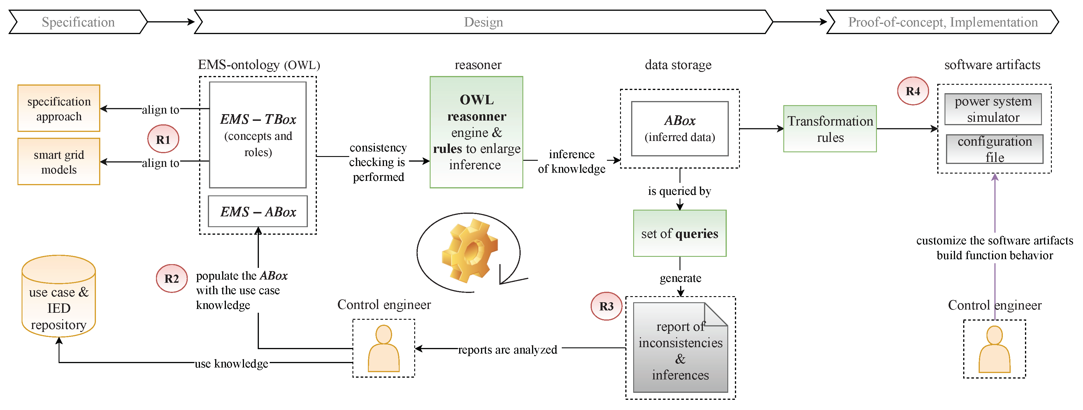
  • Generation of Software Artifacts (R4): One of the issues highlighted in Section 2.3 requires implementing EMS applications into different power system tools (i.e., design, emulator). Thereby, the generation of software artifacts at the proof-of-concept and implementation phase should be assured. MDE invokes two types of transformations: Model-to-model (M2M) and Model-to-text (M2T) transformations by the setting up of transformation rules. Both transformations should be carried out at the design stage, and this would improve the rapidity and interoperability of the EMS engineering process. The generation of code and models from an EMS platform-independent model is part of the requirement R4.
In summary, current efforts to face the issues encountered during the EMS development process were evaluated. Thereby, current standards for the power utility automation domain are studied (e.g., IEC 61850). As a result, R1 motivates the use of existent information models. Moreover, approaches that support the whole chain of the development process (e.g., SGAM, PSAL) are compared to realize the specific points that need to be targeted to address the complexity issue. This results in R2, and it searches for a common vocabulary for BESS UCs. Afterwards, the overlapping within a multi-functional BESS motivates the assessment of ontologies in smart grids. That topic was already addressed in [38]. Hence, R3 envisages the implementation of the outcomes from the mentioned study in EMSOnto. The interoperability issue is tackled by model-driven engineering techniques, and this is conceptualized in R4. As a result, the basis for the conception of EMSOnto are formulated under requirements R1-R4.

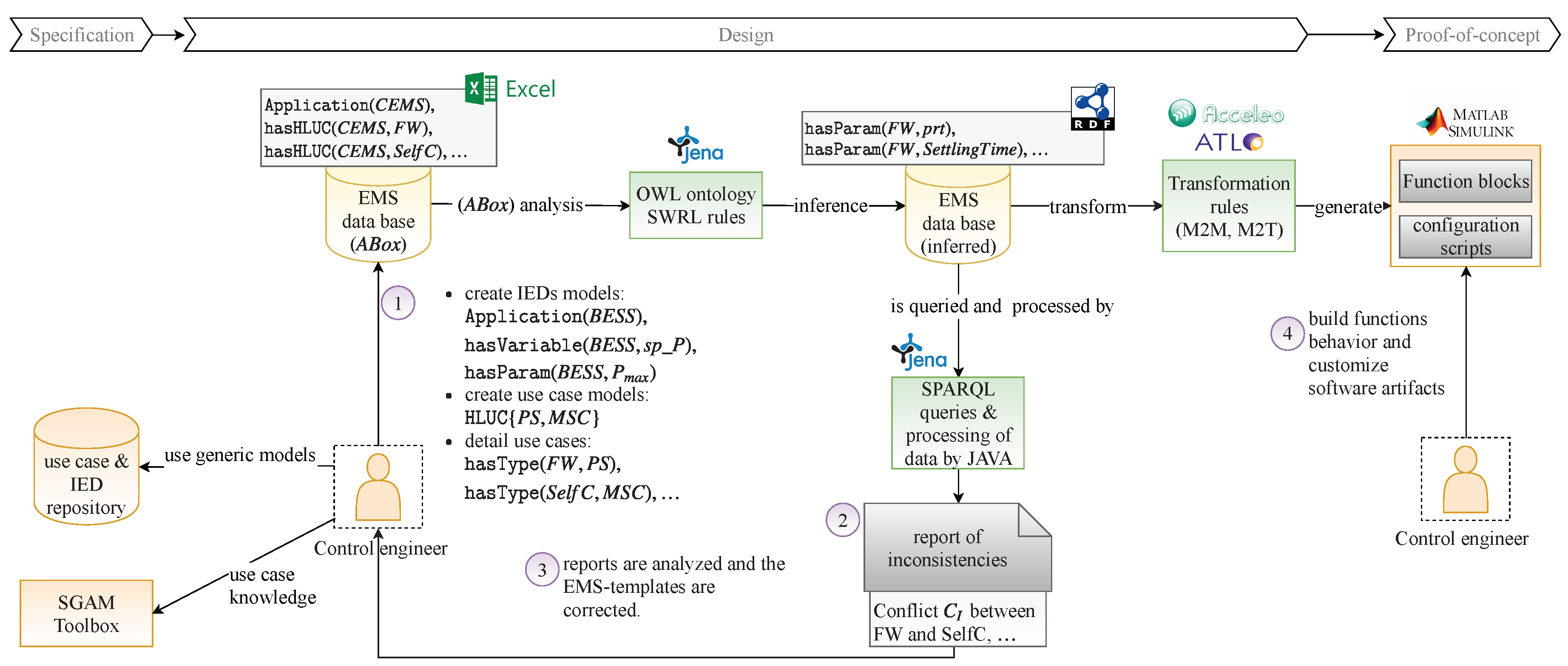
4. Application Development with the EMSOnto Approach

In the last section, the need for an engineering support for designing multi-functional BESS control applications has been identified and discussed. This design is driven by the fulfillment of certain requirements (i.e., R1–R4). In this context, model-driven engineering together with ontologies are combined to offer a flexible solution—the so-called EMSOnto approach. This section introduces the main ideas and concepts behind it, especially the EMS-ontology which forms the main part of this approach. Thus, the design of the EMS-ontology is presented and discussed accordingly to requirements R1–R4. Additionally, a user-friendly method to populate the ontology is also addressed.

4.1. General Overview of the Approach

The whole picture of the EMSOnto framework and the support it provides to control engineers during EMS-development are shown in Figure 2. Across the different phases in the design and development process, requirements R1–R4 are properly addressed.
As an initial step, the control engineer defines the specification of an EMS by selecting one of the approaches from the list presented in Section 3.2. This knowledge may be used during the design stage to pre-fill the assertional component of the EMS-ontology ( A B o x ). Additionally, at the design phase, further information about structure and data exchanged in the scope of the EMS application is included within the EMS- A B o x . Current smart grid data models ease the realization of the EMS- A B o x by providing knowledge of IEDs and corresponding control functions (like the Frequency-Watt or Volt-VAR functions in IEC 61850 [12]). Such device-specific models are usually stored within a repository and are being made available to the control engineer during the whole engineering process.
The other component needed to fully define the EMS-ontology is the terminological box ( T B o x ). A set of axioms conforms the EMS- T B o x which serve as the basis for the inference of knowledge. A main advantage of ontologies is consistency checking of the A B o x regarding the pre-defined T B o x . This and the inference of knowledge are achieved by the setting up of a reasoner engine [39]. Additionally, a set of premises that lead to conclusions (i.e., rules) extends the quantity of knowledge that can be inferred by just the EMS- T B o x setup. On top of that, a list of queries leads to the extraction of selected data. As a result, to achieve data inference the EMS- T B o x , pre-defined rules and also queries are implemented by the EMSOnto. This setup is transparent to the control engineer.
Once the A B o x is fully defined and compliant to the T B o x , corresponding reports can be generated showing the critical and severe issues regarding the A B o x . At this stage, the control engineer gets helpful information about potential controller conflicts (i.e., at A B o x level) which can be solved before starting the implementation and proof-of-concept of EMS applications. Additionally, a list of potential conflict-solving solutions per triggered inconsistency is also generated. At this stage, control engineers require adapting the EMS- A B o x to reach an error-free EMS database. The final step in the overall process is to use model-driven engineering techniques in order to generate software artifacts and platform-specific code as outlined in Figure 2.

4.2. Core EMS-Ontology Use Cases

The core part of the EMSOnto approach as depicted in Figure 2 is based on the design of the EMS- T B o x . This involves a deep understanding of the EMS application itself, the services deployed within it, and the components controlled or monitored by the EMS. Because of that, an evaluation of services provided by the EMS is carried out. Those services are exemplified by use cases UC1–UC5 (already introduced in Table 1). From that, a pattern to guide the design of the EMS- T b o x is presented.
Typically, an EMS application involves a main controller and its environment as shown in Figure 3. The controller K carries out the corresponding control and optimization functions. The EMS itself is focused on the provision of multiple services supported by a BESS (see UC1–UC5). Thus, many services ( S e r v i c e 1 , , S e r v i c e n ) may be embedded in K. Each service follows specific control strategies. Hence, they need to measure states from the electrical process G, composed by IED such as batteries, smart meters, photovoltaic generators, etc. Furthermore, services should receive setpoints ( w 1 , , w n ) to regulate certain states of the electrical process (y). As a result of the regulation process, command values (u) are sent to G. Those control values are taken into account by G as long as a setpoint (m) is available within IEDs. A similar occurrence is noted in the measurements f. They are available only if the IEDs give access to their states (s). Besides the aforementioned values, a set of parameters within the controllers ( K 1 , , K n ) defines the control behavior. For instance, the controller within UC1 ( Q b a t = α V p c c + β ) requires the setting up of α and β .
Use cases UC1–UC5 are mapped into the control scheme presented in Figure 3 resulting in Table 3. This mapping validates the modelling of EMS by the previous mentioned information (i.e.,  w , S e r v i c e , f , etc.). Other elements to be considered in the modelling of EMS are systems that interact with EMS besides the process G. The aforementioned use cases address services interacting with other stakeholders spread out in the distribution network (Distribution System Operator (DSO)) and the transmission network (Transmission System Operator (TSO)). In certain use cases, those systems, denoted by A, require setting variables of K remotely (e.g., parameters). For instance, UC2 deploys within the controller K the logic P b a t = γ F g r i d + θ . The charging of the battery ( P b a t ) may be configured remotely by the TSO by modifying the parameters γ and θ . Furthermore, case A needs to monitor values from K, and the controller K should be capable of sending status values (s). At the same time, A would receive feedback (f) from K. This leads to the conclusion that systems A , K and G share many similarities and can be represented under a common pattern composed of variables shown in Figure 3 and Table 3 (i.e., y , u , w , K , S e r v i c e , …).

4.3. Alignment with Smart Grid Domain Models

The EMS-ontology is aligned with smart grid domain standards to provide a broadly accepted generic use case representation, covering requirement R1. In this context, appropriate domain approaches have been analyzed and used as basis to formulate the EMS-ontology. In the following, the concepts taken from those approaches are outlined.
The structure of the EMS-ontology is motivated from concepts defined within the SGAM framework [24] and by elements introduced in the generic use case suggested by the Smart Grid Coordination Group (SGCG)—sustainable processes [40]. Both approaches are being used in various smart grid research and demonstration projects and are taken as a basis for modelling use cases [25], indicating a broad acceptance of them by the power system community. The study [40] suggests a classification of devices, actors and systems involved in a use case. Some of them are following outlined: the concept High Level Use Case (HLUC) gives a general idea of a function and is technology-neutral. An HLUC invokes Primary Use Cases (PUC) to detail its functionalities. In turn, the concept System is an arrangement of components and systems to accomplish a use case. The mentioned concepts are taken as a basis for modelling the function layer of the EMS-ontology.
Previous studies carried out in Section 3.1 presented a list of smart grid data models. Among them, this article selects an IEC 61850 approach because of its maturity and the availability of data models for power system components and functions mainly concerned by UC1–UC5. The standard IEC 61850-7-3 [41] proposes data models for run-time signals in a communication structure. Hence, the definition of common data classes for status information (CDCStatusInfo), measured information (AnalogueInfo), control signals (CDCStatusCtl, CDCAnalogueCtl), status settings (CDCStatusSet), etc. The attributes of that data are of type Boolean, TimeStamp, String, etc. The mentioned concepts motivate the design of the information layer within the EMS-ontology.

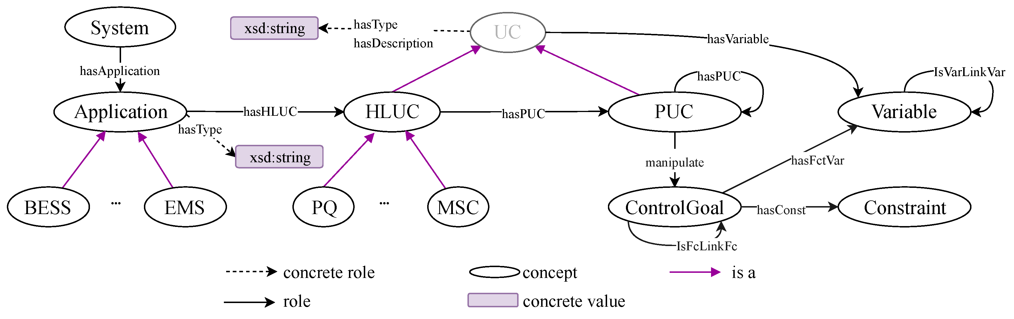
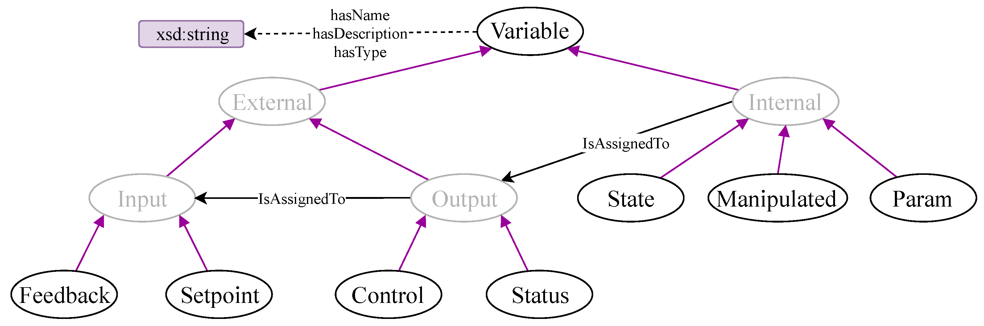
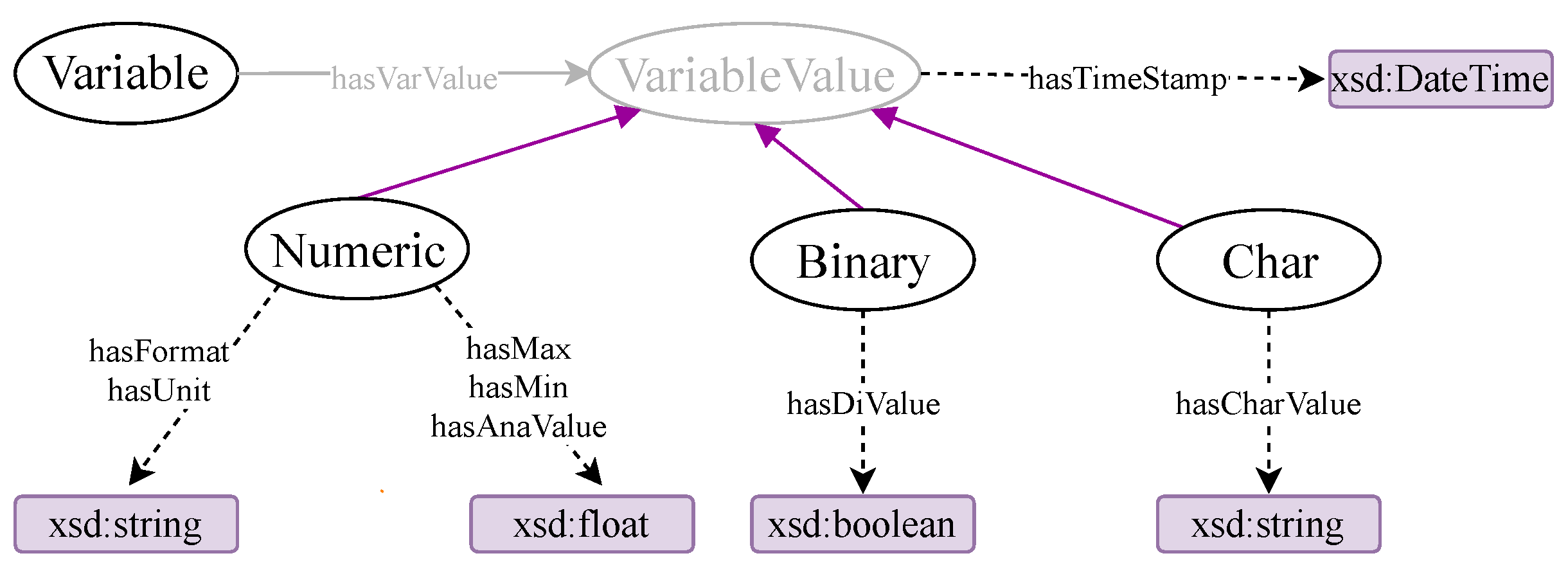
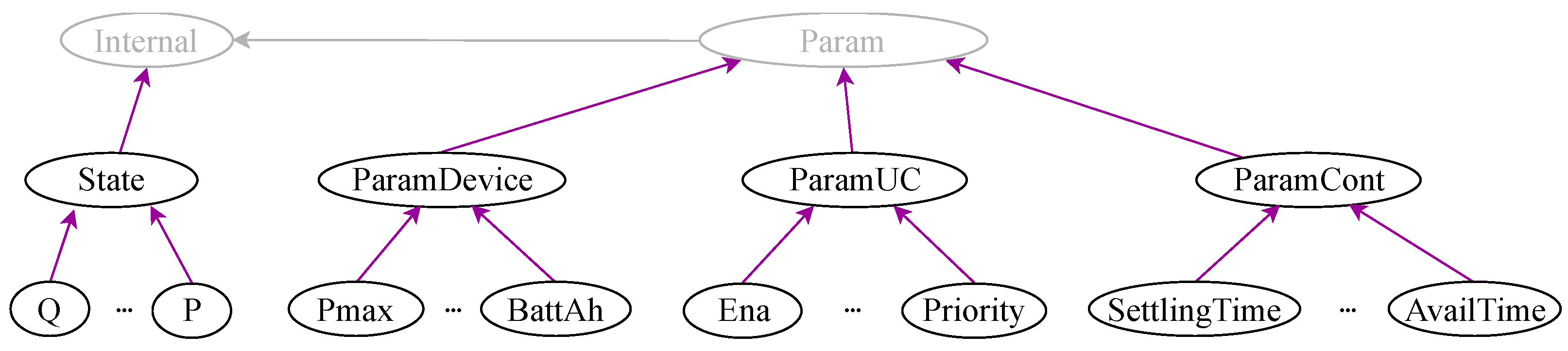
4.4. EMS-Ontology for Modelling BESS Applications

This section provides an overview of the core elements of the EMS-ontology covering concepts, roles, individuals and axioms.
As shown in Figure 3, the implementation of any UC requires the modeling of a controller K, external systems A and electrical devices defined as components of the process G. The aforementioned elements ( A , K , G ) are represented by the concept Application. Hence, Application contains sub-classes of type Battery, EMS, Meter, etc. The concept System is created as a root of the EMS-ontology. It gathers Application by the role hasApplication. As a consequence, a System is composed of control applications (e.g., EMS), external systems (e.g., SCADA) and electrical devices (e.g., BESS, PV). On the other hand, the controller K may implement more than one service ( S e r v i c e 1 , , S e r v i c e n ). To represent those services, the concept HLUC is introduced. For instance, voltage control, Primary Control Reserve (PCR) and self-consumption are abstracted by an HLUC. Furthermore, a categorization of HLUC is carried out by the concepts: Power Quality (PQ), Power Stability (PS), Minimization of Supply Costs (MSC), etc. [4].
Further details of an HLUC are given by a PUC, where the services provided by a HLUC are listed. Moreover, a PUC may contain other services, which in turn are also represented by a PUC. For instance, a PUC(voltage control) requires embedding further services such as a PUC(state estimator) and PUC(PI controller). To achieve that, the role hasPUC is created. It has the concepts PUC, HLUC as domain and PUC as range. Additionally, in case a PUC requires implementing a control scheme, the concepts ControlGoal and Constraint are suggested. ControlGoal represents a control problem lim t ( y r e f y ) 0 or an optimization problem M i n i m i z e f ( x ) subject to g i ( x ) 0 , h j ( x ) = 0 constraints. The equality and inequality constraints are represented by the Constraint concept.
The introduced concepts and roles are illustrated in Figure 4. To fully understand such representation, it is imperative to comprehend the core elements of an ontology (i.e., role, concepts, etc.) [26]. The formal representation of EMS-ontology is based on DL [27] extended with the concrete-domain concept [42]. A full description of it is given in Appendix A.
The implementation of a multi-functional system within the controller requires the exchange of information with the field process and other systems. A model of this data is formally defined by a set of concepts having as the main class the concept External (see Figure 5). External is of type Input or Output. An Input is classified by Feedback and Setpoint. In turn, the concept Output is specified under Control and Status. A mapping of those concepts to the scheme in Figure 3 is stated as follows: Control ( u ) , Setpoint { w 1 , . . . , w n , m } , Feedback ( f ) , Status ( s ) .
On the other hand, internal variables of A , K , G are modeled by the Internal concept. Thereby, Internal is structured under State and Param. Param represents variables that do not change dynamically (i.e., parameters). State conceptualizes variables that change over time. For instance, if G is represented under a Linear Time Invariant (LTI) Single Input Single Output (SISO) system x = A x + b u , then the variable x is represented by a State and b by a Param.
Values attributed to dynamic and static variables may be binary (i.e., 1 and 0), numeric data (i.e., continuous and discrete) and character. Those are represented by Binary, Numeric, Char concepts. Attributes assigned to them are modeled by the roles hasTimeStamp, hasUnit, hasFormat, etc. (see Figure 6). The role hasTimeStamp is used to reach accuracy in acquired values, enabling the synchronization of an internal time (e.g., time in K) with an external time (e.g., time in G). Other attributes of numeric values such as the format, unit and range are also addressed.
UCs embedded within an EMS that involves battery support are surrounded by common particularities. Thus, a pattern that represents a generic UC can be reached (i.e., HLUC or PUC). One of those particularities is based on the fact that a UC is bound to a minimal storage capacity. For instance, a PCR use case requires a minimum of 1 MW to allow a pool of small BESS to participate [2], hence the concept BessSize. In a multi-functional BESS context, the battery needs to share its full capacity among services. Thus, the capacity rented per HLUC is modelled by the UCAh concept. An example of this is presented in UC5, where three services rent the whole capacity of the BESS. Household, PCR, and voltage control rent 20%, 40% and 40%, respectively. Those values are modelled by UCAh. On the other hand, not all the UCs are enabled at the same time, thus a flag that represents the current operation of a UC is modeled by Ena. Moreover, a State-of-Charge (SoC) is calculated per UC and represented by the concept UCSoC. This value monitors the support given by a battery to a certain UC and guides the monetization of provided power. Furthermore, a way to manage conflicts when more than one UC operates is by setting up priorities, hence the concept Priority.
The mentioned concepts are subclasses of the concept ParamUC (see Figure 7). Additionally, parameters of a battery are grouped and modelled within the concept ParamDevice. For instance, the concept Pmax represents maximum active power to be set into the battery and BattAh the capacity of a battery. States of an electrical device such as active power, reactive power, etc. are modelled within the concept State by P, Q, respectively. In addition to this, information regarding controller requirements such as error, settling time, available time, etc. are represented under the concept ParamCont.
Concepts and roles of the T B o x component were previously addressed. They enable the classification of EMS-knowledge by concepts and the modeling of relations between data according to roles specification. Besides this, axioms defined within the T B o x and a set of rules guarantee the inference of implicit data from initial knowledge stated by domain experts. An extract of those rules and axioms are described by DL language and SWRL in Table 4 as follows.

4.5. Templates for Application Design

This section addresses requirement R2. Thereby, a mechanism to instantiate the previous introduced EMS- T B o x is proposed, resulting in the realization of the EMS- A B o x .
In order to provide the necessary information about the EMS, EMSOnto proposes the use of EMS-templates, a set of spreadsheets providing an environment for collecting and storing EMS-application related data. In this context, the usability of those templates is demonstrated by considering use case UC5 as an example.
The structure of UC5 is represented in Table 5. From there, the following knowledge is available: A System ( S y s ) contains four applications: Application { B a t t e r y , H o u s e H o l d , M e t e r , E M S } . In addition to that, an application type is conferred to them by instantiating the role hasType. Hence, hasType { ( B a t t e r y , B E S S ) , ( H o u s e H o l d , L o a d ) , } . This allows for importing models already defined within the IED repository such as BESS, Meter, Load. The Application ( E M S ) requires providing three services that are represented under HLUC { V o l t a g e C t r , F W , S e l f C } , the description of them is given in Table 5. Sub-concepts of HLUC (e.g., PQ, PS) are introduced to classify the services, hence the definition of hasType { ( V o l t a g e C t r , P Q ) , ( F W , P S ) , ( S e l f C , M S C ) } . Furthermore, an extended specification of functions within HLUC are given by the role hasPUC as follows hasPUC { ( V o l t a g e C t r , P I C o n t r o l ) , ( F W , K 1 ) , ( S e l f C , K 2 ) } . The first pair represents the assertion: an HLUC called V o l t a g e C t r contains a PUC called P I C o n t r o l (i.e., PI controller). The same is expected for the other pairs. Further details of an HLUC and PUC are hereinafter given.
The concept ParamUC suggests parameters for a generic UC (PUC or HLUC). Thereby, the inheritance of a generic UC by the previously defined HLUC such as V o l t a g e C t r would generate a list of attached parameters. As a result, the inference of the following assertions is achieved: Priority ( p r t ) , UCSoC ( S o C ) and hasParameter { ( V o l t a g e C t r , p r t ) , ( V o l t a g e C t r , S o C ) } . The role hasParameter represents a sub-role of hasVariable having as a range the concept Param. The priority and SoC assigned to V o l t a g e C t r are represented by Priority ( p r t ) and UCSoC ( S o C ) , respectively (see Table 6). Other parameters were also generated, but not presented in the table.
A PUC usually needs to read measurement values from a process (G), and, according to stipulated references, a control algorithm is carried out and control commands are sent back to G. Bringing this to the UC5 example, a PI controller searches for the control of the voltage deviation at the PCC point (i.e., δ V ). To this end, the voltage of the PCC point ( f d _ V p c c ) is measured and retrieved from a meter. Additionally, a control signal is sent to charge or discharge the battery ( c t _ Q b a t ). Formatting those assertions according to the A B o x syntax produces the following instantiations: hasControl ( P I C o n t r o l , c t _ Q b a t ) , Control( c t _ Q b a t ), hasFeedback ( P I C o n t r o l , f d _ V p c c ) and Feedback( f d _ V p c c ). The role hasControl was introduced in Table 4, and a similar logic applies for hasFeedback, but having as range the concept Feedback. Table 7 shows the EMS-template to gather the aforementioned knowledge, and a detail of variables’ attributes is also exposed.
The table referred to also exposes the knowledge needed to represent the control goal assigned to PUC( P I C o n t r o l ). The value to be regulated by PUC( P I C o n t r o l ) is represented by ControlGoal ( C g 1 ) and manipulate( P I C o n t r o l , C g 1 ). Due to ControlGoal ( C g 1 ) searching for the regulation of ( V p c c V n o m ), the instantiations Manipulated( V p c c ) and Param( V n o m ) are created. The association of them to ControlGoal ( C g 1 ) is given by the role hasFctVar, previously introduced in Table 4.
Elements within the process G and external applications A are also modelled by the EMS-ontology using the previously presented templates. Benefits arising from EMS-template practices are discussed below:
  • Knowledge is consistent with the T B o x : EMS-templates set restrictions to the data gathered within the spreadsheets. Control engineers manually fill those spreadsheets, where data entered is pre-checked to be aligned to the already specified T B o x . For instance, the knowledge: a control signal is assigned only to variables of type setpoint, is represented by the axiom C o n t r o l I s A s s i g n e d B y . S e t p o i n t within the T B o x . Due to EMS-templates being built under the T B o x basis, only setpoints can be associated with control variables in the scope of EMS-templates.
  • Gathering unlimited amount of data: None of the approaches already presented in Table 2 support control engineers with an easy collection and treatment of data. EMS-templates ease the gathering of data because of the tabular format. Moreover, filtering, comparison, ordering, exporting, data formatting, etc. are also possible in a large set of tools to process tabular format (e.g., Microsoft Excel, OpenOffice, LibreOffice Calc, etc.).
  • Setting-up of models: EMS-templates facilitate the creation of pre-defined models to be stored within the IED and use case repository for further use (e.g., V o l t a g e C t r , P I C o n t r o l ). Those models are afterward assigned to individuals of type EMS, BESS, HLUC, etc. by the role hasType. Moreover, EMS-templates enable the inspection of available models within the repository.

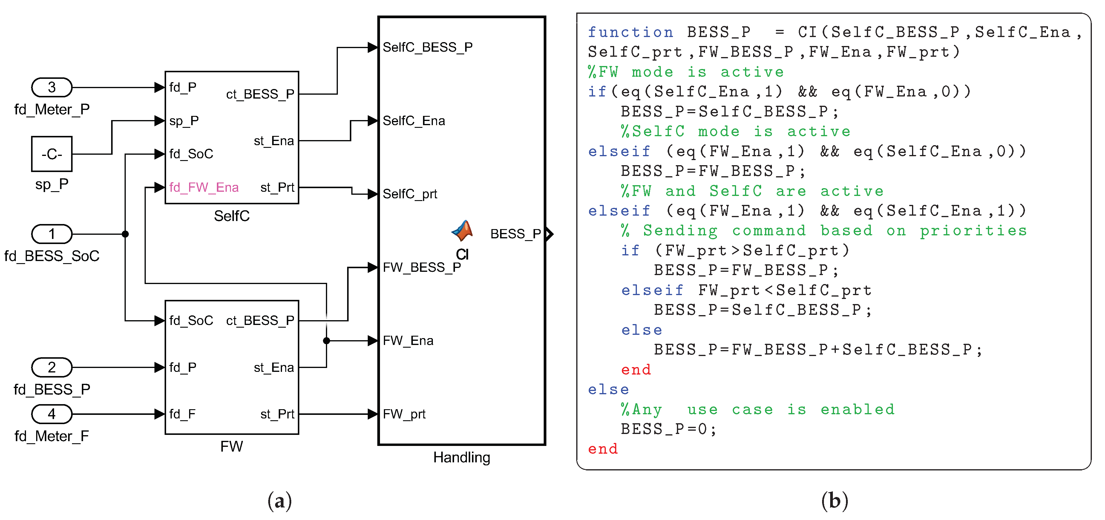
4.6. Controller Inconsistencies Identification

At this stage, all the required knowledge is gathered through EMS-templates. Further analysis enables consistency checking and inference of conflicts. Consistency checking determines if the A B o x is an instance of the T B o x . Once this is accomplished, inferences within the A B o x are discovered due to axioms defined in the T B o x and also a set of rules as depicted in Table 4. This section presents the inconsistencies addressed by EMSOnto, conforming to the requirement R3.
A deep study of conflicts identification and handling is carried out in [37]. A classification of conflicts types ( C I C V I ) is formally defined and evaluated there. The encoding and formulation of conflict detection are defined by DL queries. The ontology defined in [37] is considered in the EMS-ontology design. As a consequence, EMS-ontology is able to respond to conflict identification and their handling. To cover the mentioned features, an extension of EMS-templates targeting knowledge especially important to conflict detection is carried out. An extract of those EMS-templates is presented in Table 8.
The example in Table 8 states assertions regarding a control goal and its environment in order to investigate the conflict C I . To this end, the following assertions are included: manipulate { ( p u c 1 , C g 1 ) , ( p u c 2 , C g 2 ) } , Control(x), Manipulated(y), hasFctVar { ( C g 1 , x ) , ( C g 2 , y ) } and IsVarLinkVar ( x , y ) . Applying the axioms regarding the role manipulate and hasFctVar defined in Table 4, the inference manipulate ( p u c 1 , C g 2 ) is raised. Inferred knowledge is highlighted in Table 8.
The aformentioned knowledge is enough to investigate the conflict C I by executing the query Q C I given by the axiom: C o n t r o l G o a l 2 M a n i p u l a t e d . P U C , which investigates control goals manipulated or affected by at least two different UCs. The execution of that query concludes that ControlGoal{Cg2} and ControlGoal{Cg1} are in conflict with type C I .

4.7. Generation of Software Artifacts

As a final step, the generation of code from a neutral-technology platform is achieved. This code is not restricted to programming languages. Thus, other kinds of software artifacts such as documentation or configuration files may be produced as well. To accomplish that, specific information from EMS-templates is extracted and formated according to a target platform. That information is gathered by the means of selected queries. A non-exhaustive list of them is presented in Table 9. Information retrieved from query Q I helps to gather the attributes regarding the status of an HLUC (i.e., enabled or disabled). Besides this, the query Q I I is used to know the priority values set into a HLUC. On the other hand, reports that show the functionalities provided by an EMS can be obtained from the queries Q I I I Q V .
In this work, a MATLAB/Simulink block is generated as well as MATLAB-code (for details, see Section 5). It should be stressed that EMS-ontology do not offer support for function behaviour representation. Indeed, in the related work section (see Section 3.2), it is mentioned that other approaches such as IEC 61499, IEC 61131-3 and MATLAB/Simulink cover adequately that feature. Hence, EMSOnto is meant to work with the support of other approaches to accomplish a full control application implementation.

5. Proof-of-Concept Evaluation

In this section, the steps to be followed by a control engineer to achieve the design and validation of a selected use case example by the support of EMSOnto are shown. In this context, the phases specification, design, proof-of-concept and laboratory validation are covered. The realization of the mentioned development process enables demonstrating the benefits of EMSOnto as well as to grasp its limitations. Moreover, potential future work to improve EMSOnto are also apprehended.

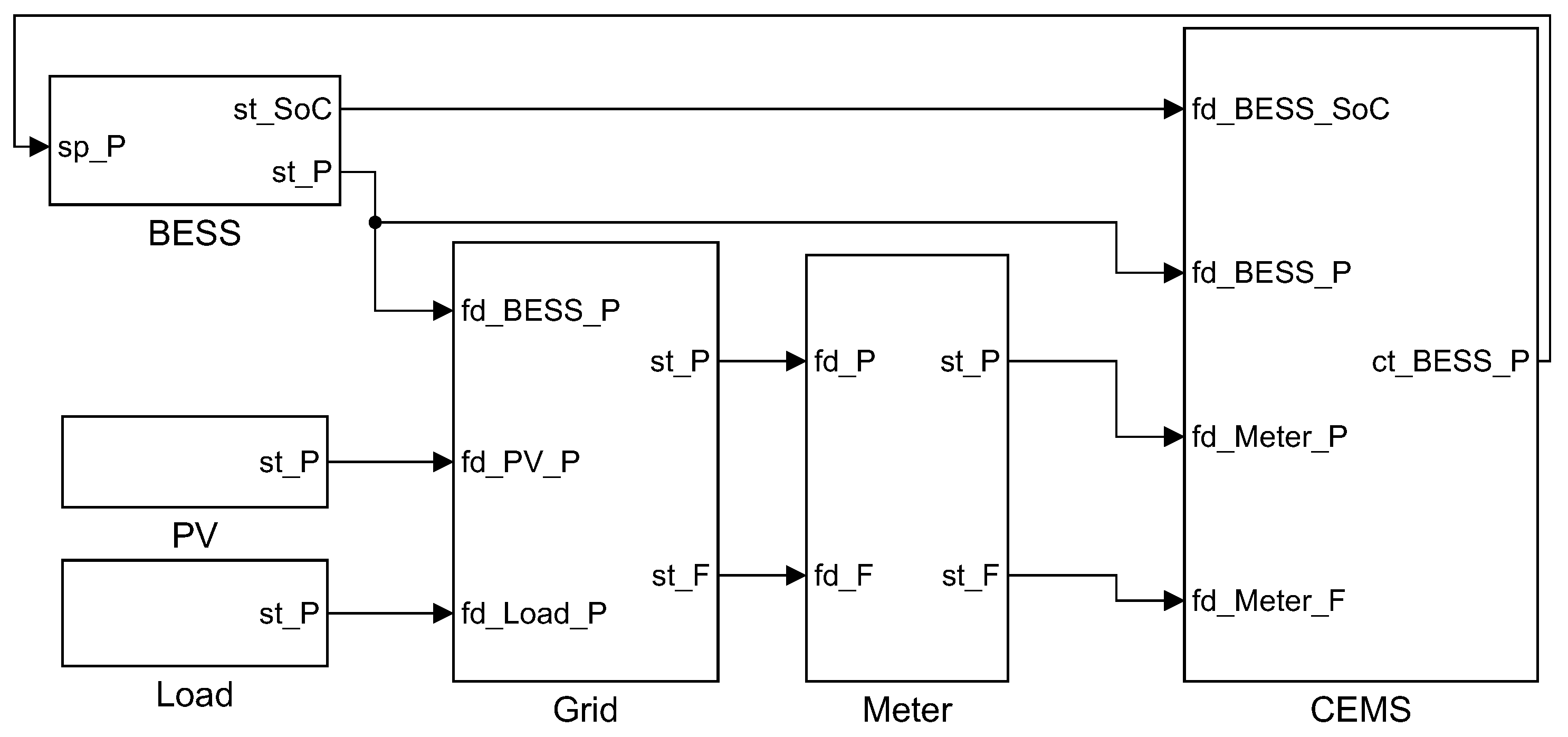
5.1. Framework Prototype and Validation Example

EMSOnto is evaluated under the execution of a control application that implements an arrangement of use cases referenced in Table 3. The control application to be analyzed implements Frequency-Watt (FW)-UC2 and Self-Consumption(SelfC)-UC3. This UC example is called Customer Energy Management System (CEMS), a schema of the CEMS architecture is depicted in Figure 8. Mathematical models of the battery and control strategies embedded within the CEMS, besides profiles for PV generation, load consumption and grid behavior are outlined below.

5.1.1. BESS Model

The used battery model follows the mechanisms as described in [43]. Thereby, the model is represented by a voltage source ( E b a t ) in series with a resistance ( R b a t ) as indicated in Equation (1). The voltage of the battery ( V b a t ) depends nonlinearly on the SoC of the battery ( S o C b a t ), and this is derived from the value of E b a t given by Equation (2). The identification of the parameters A and B are detailed in [43]. The S o C b a t is estimated by integrating the battery’s current ( I b a t ) on an interval time as shown in Equation (3), where Q represents the battery’s total capacity and S o C ( 0 ) the initial SoC:
V b a t = E b a t R b a t I b a t ,
E b a t = E 0 k ( 1 S o C b a t S o C b a t ) Q + A e B ( 1 S o C b a t ) Q ,
S o C b a t = S o C ( 0 ) + I b a t Q d t .

5.1.2. PV, Load, Grid Profiles

The PV DC generation was obtained from a model dependent in temperature and irradiance level as suggested by [44]. The temperature and irradiance data are measured with a sampling rate of 60 s and were taken over the year 2005 in Vienna, Austria from the satellite-derived HC3 Archives Web service [45]. A 60 s PV DC measurement profile is used as input data for the PV inverter model. This DC measurement is converted into AC power by considering an efficiency conversion factor. Active power generation data from Austrian households was provided by the project Autonomous Decentralised Renewable Energy Systems (ADRES) [46]. The measurements correspond to the year 2009 and are taken with a resolution of 1 s. On the other hand, the frequency profile was obtained from ENTSO-E Netzfrequenz [47] and corresponds to January 2018. The power of the grid is calculated from Equation (4) assuming that the measurements P b a t , P p v , P l o a d are known:
P g r i d + P b a t + P p v + P l o a d = 0 .

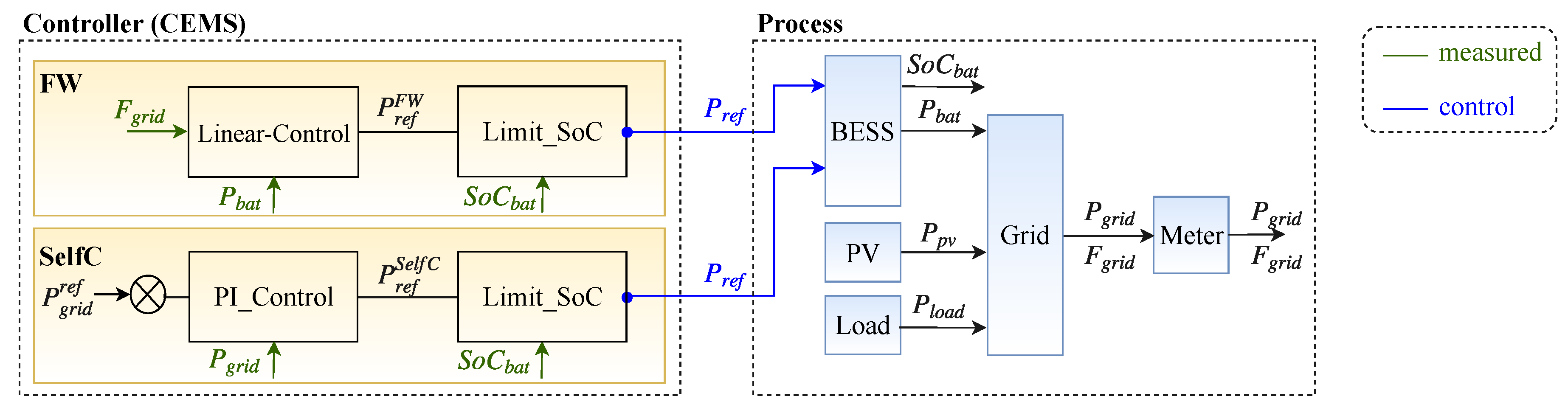
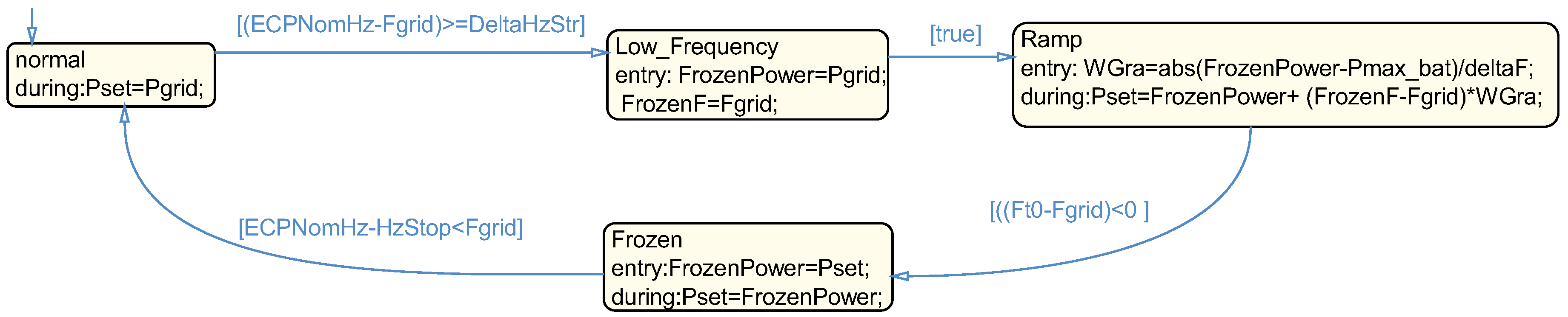
5.1.3. Control Mechanism

The CEI 0-21 standard specifies a frequency-dependent active power limitation for DER connected into the low-voltage grid [48]. Guidelines defined in that standard are fulfilled in the FW mode. In that sense, FW commands the active power of the battery to balance the frequency of the grid as stated in Equation (5). The resulted active power value P r e f F W is restricted to technical limitations of the battery (i.e., SoC and active power limits) as indicated in Equation (6). SelfC controls the BESS to assure that no energy from the grid is taken. To achieve that a PI controller is designed by following Equation (7), the resulted active power value P r e f S e l f C is also restricted by Equation (6):
Δ P r e f F W = α Δ F g r i d ,
S o C m i n < S o C < S o C m a x , P b a t m i n < P b a t < P b a t m a x ,
e = P g r i d r e f P g r i d , P g r i d r e f = 0 , P r e f S e l f C = K p e + K i 0 t e ( τ ) d τ .
The specification, design and proof-of-concept of CEMS are deployed under EMSOnto, and these steps are addressed in the following.

5.2. Realized Development Example

This section focuses on the steps carried out by the control engineer in order to realize the aforementioned CEMS application. The whole realization process is structured in four steps as shown in Figure 9. The first step is focused on the description of function and information domain of the CEMS, and this knowledge is gathered within the EMS- A B o x . This is realized by the control engineer having as a guideline the EMS-templates. Once the EMS- A B o x is filled, an analysis to infer implicit knowledge is undertaken by one engine reasoner. The inferred data is queried to evaluate inconsistencies that need to be solved before any further design of the CEMS, and those inconsistencies are presented in the form of reports. They are analyzed by the control engineer. This in turn performs a clearance and corrections over the EMS- A B o x . This process is repeated until the control engineer approves the absence of inconsistencies within the EMS- A B o x . The EMS- A B o x is transformed into software artifacts that are useful during the proof-of-concept phase. A clearance and adjustment of them is also required. Details of the aforementioned steps are explained as follows.

5.2.1. Step 1: CEMS Description via EMS-Templates

Control engineers employ the EMS-templates to specify knowledge about the information, function and component layers of the CEMS. This action is referenced in Figure 9 by Step 1 and detailed in the following paragraphs.
In the specification phase, a list of approaches are offered to control engineers to formally describe the CEMS (e.g., UML, SysML) as exposed in Table 2. Among the different options, the SGAM-Toolbox was chosen. Hence, a representation of the CEMS previously outlined in Figure 8 is matched to the SGAM matrix (information layer), where components of the system under study and also the exchanged information across them is illustrated, see Figure 10. The CEMS controller is located at the customer premises. The BESS and PV are situated at the DER-domain and field/process-zone. The meter located at the PCC point belongs to the customer-domain and field-zone. In turn, the low-voltage distribution grid and loads are matched to the process-zone. SGAM-Toolbox offers more schemes to detail the structure and behavior of control applications, covering the other layers of SGAM such as component and communication.
After the specification phase is concluded, control engineers reuse the derived knowledge at the design stage to fill the EMS-templates. One template is focused only on the structure and functionalities covered by CEMS (see Table 10). A System(Sys) is composed of Application{CEMS, BESS, PV, …}. Services carried out by them are described under HLUC, for instance Application(CEMS) owns HLUC{FW, SelfC}. A description and a type are assigned to HLUC and Application by the roles hasDescription and hasType. Hence, hasDescription(FW, active power …) and hasType(FW, P S ) belong to HLUC(FW).
A further description of HLUC is given by the concept PUC as shown in Table 11. Hence, the HLUC(FW) contains PUC{Linear-Control, Limit_SoC}. A description of PUCs is given as well as the category details (e.g., F W H Z ). Type specification leads to inherit Variables from the UC repository. Therefore, variables not inherited should be specified by the control engineer as follows: the PUC(Limit_SoC) controls Application(BESS) through Control( c t _ B E S S _ P ), the measurement of the frequency at the PCC point is derived from Feedback( f d _ M e t e r _ F ). Moreover, PUC(PI_Control) controls the battery by commanding Control( c t _ B E S S _ P ).
A generic HLUC was achieved by the definition of ParamUC and ParamCont as exposed in Section 4.4. PS and MSC being generic HLUCs, the matching of HLUC{FW, SelfC} to PS and MSC respectively derives the population of HLUCs as shown in Table 12. In this context, a priority is set to HLUC(FW) by stating ParamUC(Prt). Information related to the controller features is described under ParamCont. Hence, the settling-time of HLUC(FW) is set to 30 s and stated by ParamCont(SettlingTime).
IED data models (e.g., BESS, meter) are created by the control engineer and stored within the IED repository to be used in future EMS design. A battery model is shown in Table 13. It was not the aim of EMS-templates to gather data from control algorithms deployed within the BESS. Thus, only internal and external variables of the battery are considered within the model. In addition to this, those models assist with identifying the variables available to the CEMS such as Setpoint and Status.
The IED repository leverages models from IEC 61850, a large list of function and IED models is detailed in the standard. A model suitable to PUC(Linear-Control) is extracted from the logical node FWHZ exposed in the standard IEC 61850-90-7 [12], resulting in Table 14.
The detection of certain inconsistencies requires the gathering of extra specific information—for instance, the detection of conflict C I requires filling Table 15. That conflict looks for a coupling across PUCs or HLUCs. The C I identification is based on a proper definition of control goals to be carried out by PUCs. In this light, the variables involved within a control goal are specified (i.e., Manipulated, Control) as follows: PUC(Linear-Control) performs ControlGoal(Cg1), its objective is to manipulate the power at the electrical connection point of the battery ( P b a t ). In turn, PUC(PI_Control) satisfies ControlGoal(Cg2) and requires the manipulation of P g r i d . In addition to this, the dependency between the variables P b a t and P g r i d is derived from P b a t + P l o a d + P g r i d + P p v = 0 . Hence, Linear-Control. P b a t affects the value of PI_Control. P g r i d .

5.2.2. Step 2: Assertions Derived from EMS-ABox

This section describes the support given by EMSOnto to control engineers in order to build an error-free EMS- A B o x . In that sense, an inference process based on the knowledge reached from Step 1 is carried out. The inferred data is queried to generate reports that highlight inconsistencies within the EMS- A B o x . Additionally, conflict-solving solutions are included in those reports. Tools and approaches to implement the mentioned procedures are also introduced in this section.
Once the gathering of knowledge about the CEMS is complete (EMS- A B o x ), mechanisms for consistency-checking and inference need to be carried out. Those mechanisms are implemented by the Apache Jena framework, an open source Java framework used to implement semantic web applications. Jena provides a predefined OWL reasoner and a generic rule reasoner, especially important to SWRL rules’ definition. It is worth mentioning that Jena requires the knowledge in Resource Description Framework (RDF) format to perform any type of inference. Thus, Google Refine with RDF extension is employed to transform data from EMS-templates into RDF format.
The inferred knowledge is queried to localize any inconsistency as defined in Section 4.6. Those queries are implemented using SPARQL update, an RDF query language. A set of handling solutions to detect conflicts ( C I , , C V I ) is properly addressed in [38] and implemented by EMSOnto. In case C I and C V are raised together, EMSOnto proposes the setting up of priorities per PUC. The PUC with highest priority is considered and the others are dismissed. Knowledge needed to carry out the mentioned handling solution is attached to a PUC named C I .
The data retrieved from EMS- A B o x is formatted and handled to control engineers in the form of reports, and an extraction of those reports is shown in Table 16. The final analysis carried out by control engineers is also depicted. Due to the conflicts C I and C V being raised together, the handling solution advised by EMSOnto is PUC( C I ).

5.2.3. Step 3: Design of the EMS based on Analysis of Reports

Step 3 involves the manual work realized by control engineers to reach an error-free EMS- A B o x that will be deployed during the proof-of-concept and implementation phase.
An analysis of reports generated during Step 2 is carried out, leading in some cases to an adjustment and correction of the EMS- A B o x . This correction may depend on the handling solutions provided by EMSOnto. EMSOnto owns a set of pre-defined PUC to handle conflicts, and they are available within the UC repository. The one that manages the conflict C I and C V is PUC( C I ).
The PUC(Handling) is created by the control engineer to manage C I and C V . The type of it is assigned to C I , thus an automatic generation of variables is achieved. An extract of this is shown in Table 17. A unique active power signal to control the battery is chosen among the variables S e l f C _ B E S S _ P and F W _ B E S S _ P . The higher priority is allocated to HLUC(FW) as assigned in Table 18. Once the EMS- A B o x is updated and extended, Step 2 is executed again, and the new report does not detect new inconsistencies.

5.2.4. Step 4: Customization of the Software Artifacts

The knowledge derived from Steps 1–3 is transformed into software artifacts important for the validation of EMS. This is achieved in Step 4 by performing model-driven engineering techniques.
The proof-of-concept of the CEMS is implemented in MATLAB/Simulink. A simulink model supports a block diagram representation, code generation, simulation of dynamic systems and customized block libraries. In turn, MATLAB provides the development of algorithms in textual programming form. The EMS-templates contain information about the CEMS structure, which is transformed into block diagrams within a Simulink model. This is reached by a set of transformation rules implemented in Atlas Transformation Language (ATL) and Eclipse Modeling Framework (EMF). EMF implements the key aspects of MDE practices by exploiting the facilities provided by Eclipse tools. Furthermore, the EMS- A B o x being in RDF format, a conversion from RDF into a format to be processed and understood by EMF is required, and this is reached by employing the EMFTriple project. As a sequel, a transformation from the EMF model into a MATLAB/Simulink model (M2T) is automatically generated by the Massif framework for Eclipse, resulting in the model depicted in Figure 11, which was tailored and customized by the control engineer. A matching between knowledge regarding EMS structure in Table 10 and the Simulink/model is resulted.
An extra amount of work realized by the control engineer is the design of control strategies. The behavior to be performed within PUC{Linear-Control, Limit_SoC, …} is not considered within the EMS-templates, and this is carried out in MATLAB/Simulink by customized block libraries and MATLAB-scripts. For instance, PUC(Linear-Control) is performed by a state-flow diagram in a Simulink model. As previously stated, PUC(Linear-Control) follows the control behavior defined in the Italian standard [48]. The mechanisms to be followed due to under-frequency events are illustrated in Figure 12. When the event [ E C P N o m H z F g r i d > = D e l t a H z S t r ] takes place, active power is injected into the grid. Power injected depends linearly on the frequency, and it is calculated in the state R a m p . A return to normal condition is reached when the event [ E C P N o m H z H z S t o p < F g r i d ] is raised. E C P N o m H z is the nominal frequency, and D e l t a H z S t r and H z S t o p represent deviations from E C P N o m H z . See  Table 14.
The information regarding conflict resolution exposed in Table 17 is transformed into a block diagram as shown in Figure 13a. However, not all the connections and inputs are generated. Some of them are manually included by the control engineer—for instance, the input fd_FW_Ena within the SelfC-block. The need for that input was realized during the running of simulations.
Besides block generation, the function code embedded within the handling-block is also generated as shown in Figure 13b. The function C I retrieves the two control signals sent by PUC{SelfC} (Control{Self_BESS_P}) and PUC{FW} (Control{FW_BESS_P}). The priorities defined within the PUCs are also retrieved by the inputs S e l f _ p r t and F W _ p r t . Based on that, the code decides which control signal should be sent to the battery. The data depicted in the code is defined within the EMS- A B o x and were retrieved by performing certain SPARQL queries such as Q I and Q I I already defined in Table 9. The performing of M2T transformations is reached by Acceleo, an open-source code generator, where templates are designed according to models and a conversion from models into text is achievable.
Simulations are performed to validate the behavior of control applications within PUC { S e l f C , F W } . The power balancing required to meet P g r i d = 0 and P b a t = γ F g r i d + θ is shown in Figure 14. Parameters related to PUC(FW) function are: E C P N o m H z = 50 , D e l t a H z S t r = 0 . 04 and H z S t o p = 0 . 01 . Thereby, limits for over and under-frequency events are reached at 50.04 Hz and 49.96 Hz respectively, indicated by red and black dashed lines. At time 3640 s, an under-frequency event takes place, producing a discharge of the battery to inject more power into the grid. Once the frequency starts recovering, a snapshot of the instantaneous power is taken and used as a cap to set P b a t . This continues until the frequency value is higher than 49.99 Hz ( E C P N o m H z H z S t o p ). At that moment, the cap on the power output is removed. Additionally, the PUC(FW) is released and PUC(SelfC) is activated. Thereby, the battery is still discharging to support the load consumption, resulting in P g r i d = 0 . The control signal c t _ B E S S _ P coming from the PUC(FW) to set the active power of the battery is depicted in red color. Thereby, this setpoint is followed by the battery during the under-frequency event.

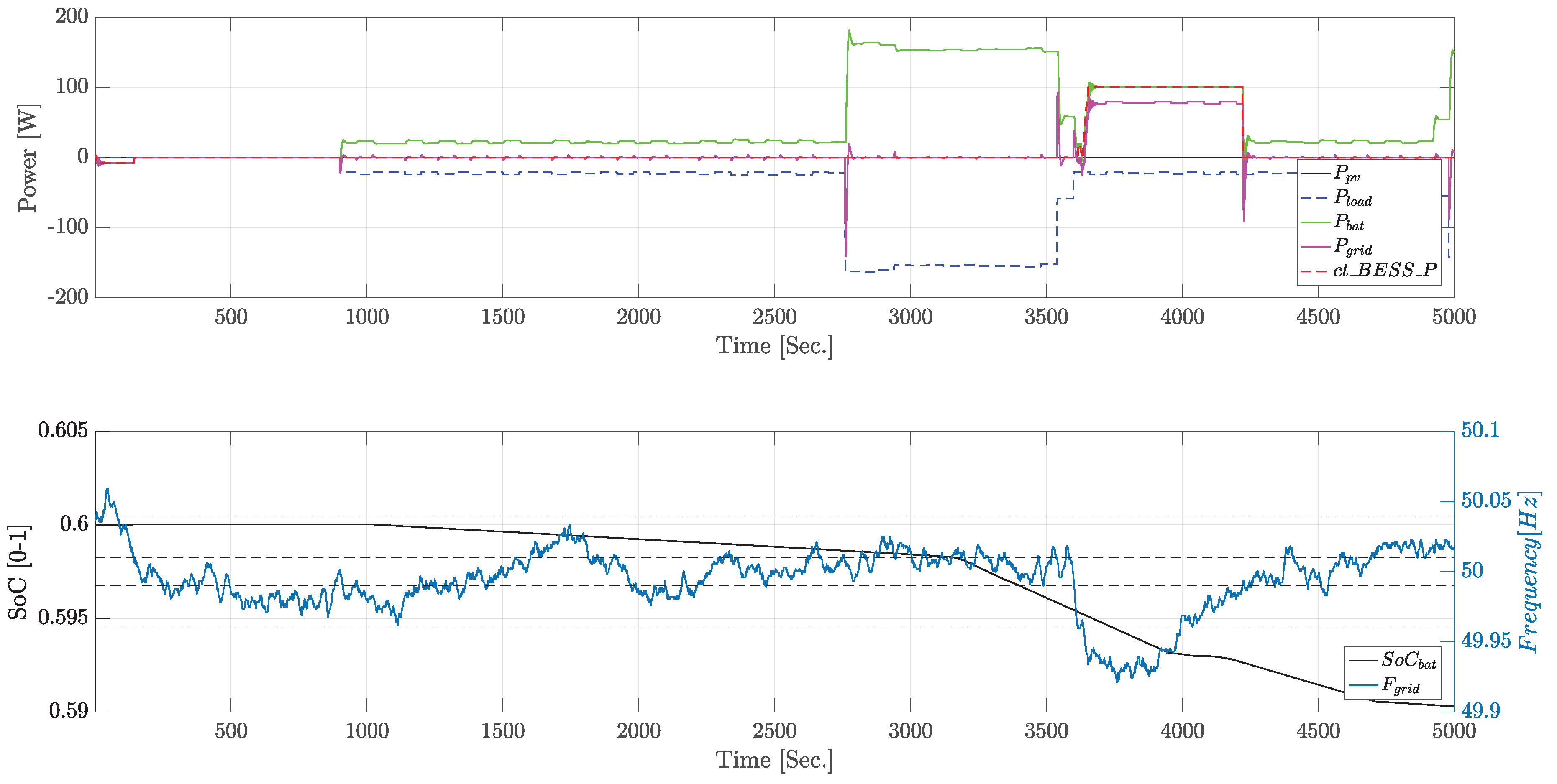
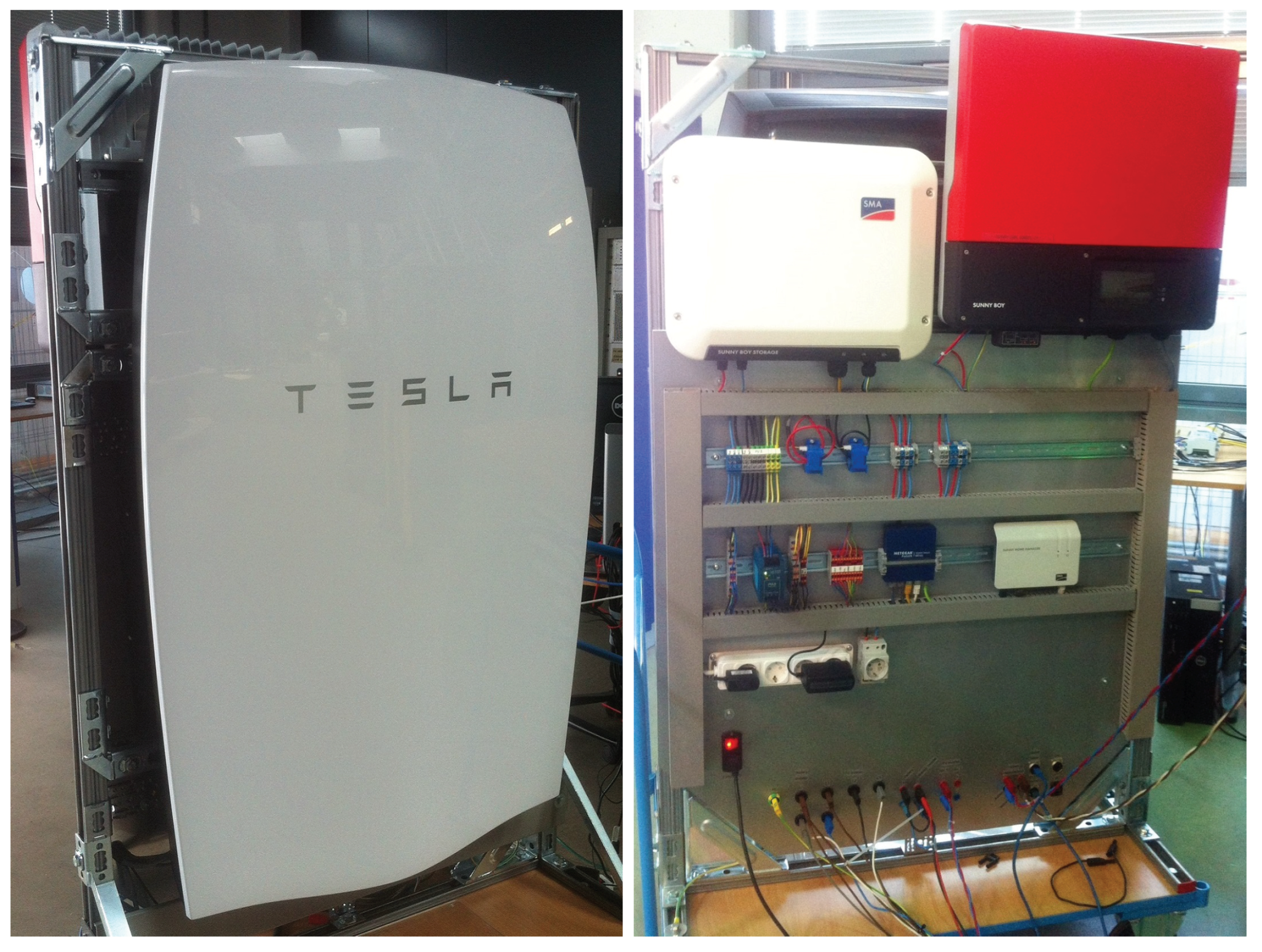
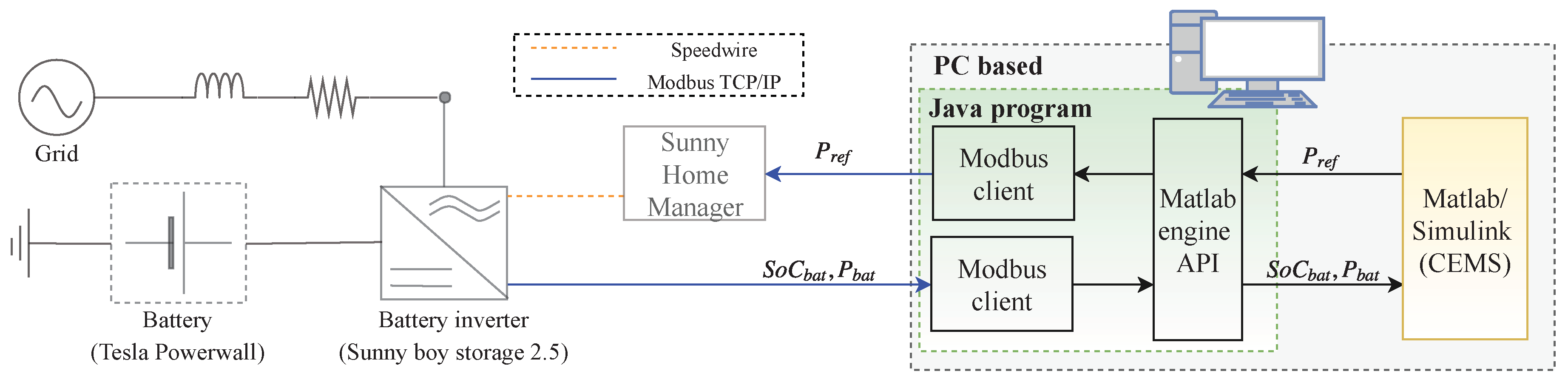
5.3. Laboratory Implementation and Results

The main objective of the laboratory implementation is to validate the executable software artifacts generated by EMSOnto and also to evaluate the benefits and limitations of EMSOnto during the proof-of-concept with real hardware devices. It is important to highlight that performance of control strategies (HLUC {SelfC, FW}) is not the main focus. A representation of the laboratory setup is illustrated in Figure 15. In order to keep a simplicity in the validation experiments, only the battery and battery inverter are represented by real hardware. In this context, a Tesla Powerwall and Sunny boy storage 2.5 are employed. The other components such as smart meter, PV generator, and loads are simulated within the power system emulator (Simulink/MATLAB) as well as the control strategies.
The battery inverter communicates battery status ( S o C b a t , P b a t ) by Modbus TCP/IP. The setting up of active power within the battery ( P r e f ) is done also by Modbus TCP/IP through the Sunny Home Manager, a control center for energy management. An interface between the power system emulator and the real hardware is needed to get and set data. Thereby, a Java program that carries out two Modbus clients and a MATLAB API is implemented. Modbus clients are configured to exchange data with the real devices. In turn, a library that enables Java programs to pass data from MATLAB to Java and vice versa supports the communication between the Java program and the Simulink model (CEMS). The hardware used in the laboratory setup is shown in Figure 16.
The results obtained from the laboratory tests are shown in Figure 17. In order to show the behavior of CEMS, a specific frequency profile with over-frequency occurrences is built. The FW mode parameters are set to E C P N o m H z = 50 , D e l t a H z S t r = 0 . 3 and H z S t o p = 0 . 1 . As a consequence, as soon as the frequency exceeds 50.3 Hz ( E C P N o m H z + D e l t a H z S t r ), the Tesla Powerwall starts taking power from the utility grid. The active power charged into the Tesla battery depends linearly on the frequency values. This dynamic continues until the battery reaches its technical limitations at 2.5 kW (Sunny boy storage 2.5 supports a maximum charge of 2.5 kW). The values of 50.3 Hz and 50.1 Hz are represented by magenta and black dashed lines, respectively.
FW mode is not requested more when frequency gets lower than 50.1 Hz ( E C P N o m H z + H z S t o p ). Thereby, at 40,640 s, the FW mode is deactivated and self-consumption conducts the battery behavior. Hence, a PI control drives the value of P g r i d towards zero. As mentioned before, only the battery is considered as real-device. Thus, P b a t and S o C b a t are real-values, and other values such as P l o a d , P p v , P g r i d , F g r i d were simulated. Communication delays and the time needed by the battery to provide the expected setpoint ( P r e f ) were considered in the synchronization between the Java program, the Simulink model and the real devices.
The lab tests point out the benefits of EMSOnto at the proof-of-concept stage and motivate the extension of EMSOnto features. In that sense, benefits lie in the formal structure behind a UC representation. Thereby, the parameters such as H z S t o p and D e l t a H z S t r to be tuned within use cases were rapidly identified. On the other hand, conception of EMSOnto tackles information and function domain but not communication domain, which should be also supported. In that sense, manual work performed by control engineers to implement communication interfaces may be reduced by extending EMSOnto. For instance, an automatic generation and configuration of Modbus clients could be achieved. On top of that, the mapping of variables between MATLAB/Simulink and Modbus clients could also be covered. In addition to this, improvements such as the extension of the battery model presented in Table 13 with the information of Modbus registers are highly recommended.

5.4. Evaluation of Requirements and Open Issues

EMSOnto is conceived under the fulfillment of requirements R1–R4. As a result, this approach claims to support control engineers during the design of EMS applications. In order to demonstrate and evaluate it, a use case example (CEMS) is designed and validated. This section analyzes how far the initial stated requirements (R1-R4) were satisfied.
Repository based on SGAM and IEC 61850. R1 requires benefitting from existent smart grid data models. Hence, EMS-ontology is conceived under the standards IEC 61850 and SGAM. This OWL ontology defines the structure of spreadsheet templates, which facilitate the creation of pre-defined models (e.g., battery inverter [19] and frequency-watt [12]) to be stored within the IED and use case repository. The referred repository is built and available to the control engineer to start the design of EMS applications. In the CEMS example, the PUC(Linear-Control) uses knowledge from a FWHZ Logical Node accelerating the collection of CEMS data.
EMS-ontology and EMS-templates. R2 searches for an ontology that reflects a common understanding of multi-functional BESS. Thereby, a pattern that models different BESS use cases (UC1–UC5) is established resulting in EMS-ontology. The proposed OWL ontology was used to detail functions, parameters and information flows within the CEMS use case. This demonstrates that roles and concepts defined in the scope of EMS-ontology are appropriate for EMS description. Population of the ontology is achieved by filling out EMS-templates. Control engineers became familiar with this method quite fast, demonstrating that it is a good practice in gathering and documenting of data at the design phase. A feature not supported by the approaches presented in Table 2.
A benefit derived from ontologies is the extraction of data from A B o x by means of queries. In that sense, once the filling process of EMS-templates is complete, a set of reports to determine EMS functional capabilities can be queried by an external system (e.g., EMO) (see Table 9). However, it is worth noting that information in the design phase may evolve during the proof-of-concept phase (e.g., a signal f d _ F W _ E n a was included during the validation of the CEMS). Hence, the final state of the EMS knowledge may differ from the information gathered at design time. Thus, a reverse engineering process [49] between the design and proof-of-concept stage is suggested to keep EMS data updated.
As mentioned before, the conception of EMS-ontology is aligned to the broadly recognized SGAM and IEC 61850 data models. Nevertheless, interoperability between EMSOnto and information models such as CIM and OPC UA should also be considered since they are strongly recommended in the semantics for smart grids [50].
Detection and Handling of Conflicts. R3 requires the implementation of the study [38] to support the design of EMS. To achieve the aforementioned, EMS-ontology and the OWL ontology proposed in [38] are aligned. Furthermore, EMS-templates are suggested to gather information mainly important for conflict identification. As a consequence, an error-free EMS- A B o x is achieved before starting any implementation of the control applications. This was exemplified by the CEMS, where conflicts C I and C V were detected and the handling solution proposed by EMSOnto was considered in order to correct the CEMS design. Nevertheless, other kinds of inconsistencies not covered by EMSOnto may be raised during the EMS operation such as an erroneous sensor (i.e., smart meter), a measurement signal with a low sampling rate or the setting up of out-of-range values into the BESS inverter. Those inconsistencies were not considered by EMSOnto, in order to detect them an observation of states over time is necessary. This would require bringing the concept of temporal logic and concrete logic into description logic as performed in [51].
Code and Model Generation. Generation of software artifacts that support the proof-of-concept and implementation phases are required in R4. Hence, code important to the proof-of-concept stage is automatically generated. This involves the creation of M2M and M2T transformations from EMS-templates into a specific platform tool. On that basis, MATLAB code and a Simulink model were generated and upload into a MATLAB/Simulink project for CEMS validation purposes. A benefit from that is the reduction of errors susceptible to be introduced during the implementation of control applications. Moreover, the software artifacts generated were integrated in offline simulations and hardware-in-the-loop tests, contributing to an acceleration of the development process.
Code and models generation were imported in a power system emulator (i.e., MATLAB/Simulink). Nevertheless, other tools such as co-simulators and communication network simulators are also important during the proof-of-concept stage. Thereby, the adaptability of EMSOnto with other tools is contemplated as future work.
A complete EMS implementation requires the establishment of control algorithms’ behavior. However, it was not the aim of EMSOnto to model the behavior of BESS use cases. A comparison and analysis of smart grid and automation approaches in Section 3.2 show that supports for implementing system behavior are available (i.e., MATLAB, IEC 61499 and IEC 61131-3). Thus, to reach a full implementation of EMS, the complement of EMSOnto with other existent smart grids and automation approaches is necessary.

6. Conclusions

A BESS provides support to many stakeholders of the grid going from end-user, distribution and transmission system operator to EMO. This support may require the deployment of a large set of use cases into an EMS. Such a development process is surrounded by different issues such as flexibility, complexity, overlapping and interoperability. Mechanisms to overcome the mentioned issues are studied in this paper; as a result, a framework (i.e., EMSOnto) to support control engineers during the design and proof-of-concept of EMS control applications is achieved.
A common understanding about EMS control applications is reached, resulting in the conception of an OWL ontology called EMS-ontology, which focuses on EMS structure and information exchanged across the EMS control architecture. Thereby, EMS-ontology is inspired from broadly accepted smart grid approaches: SGAM and IEC 61850. On the other hand, the population of the ontology is achieved by filling out spreadsheet templates (i.e., EMS-templates). Those templates ease the gathering of information at the design phase, a feature that is not provided by any of the approaches (see Table 2). Moreover, due to EMS-templates being aligned with smart grid standards, a selection of existing data models (e.g., LN from IEC 61850) was carried out to pre-fill a database that assists during the collection of EMS knowledge (use case and IED repository). It is worth mentioning that EMS-templates do not contemplate the behavior of control applications. Thus, EMSOnto needs to be supported by automation approaches such as IEC 61131-3 and IEC 61499 to achieve a full implementation.
Detection of conflicts within BESS control applications was already addressed in [38]. However, control engineers were not encouraged to use the referred study due to the amount of work involved at the design phase. They argued that conflict issues could be handled by a meticulous study of the control application. This encouraged the implementation of [38] within EMSOnto as it contains important knowledge of EMS that can be used for the inference of conflicts.
A UC example (i.e., CEMS) is developed under the EMSOnto basis showing the benefits and restrictions of the framework. Moreover, from that implementation, a list of recommendations for future work came out. Hence, it is suggested to interoperate EMSOnto with other power system tools, in order to perform reverse engineering methodologies for the consistency between the design and implementation phases. Additionally, the use of temporal logic to investigate other kinds of inconsistencies is also encouraged.
Specific planned future work concentrates its efforts in providing flexibility to EMSOnto and to investigate mechanisms for automating the development process. This contemplates enlarging the inference of knowledge and generating software artifacts relevant for the implementation stage. Moreover, information sources available at the specification phase such as IED configuration files, information models, etc. will be exploited to enhance the collection of data within the EMS- A B o x .

Author Contributions

C.Z. wrote the paper and carried out the conceptualization, investigation and validation of the work. F.P.A., J.K., and T.I.S. participated in the conceptualization of the proposed approach and reviewed the final manuscript. T.I.S. supervised the overall work.

Funding

This work is partly supported by the Austrian Ministry for Transport, Innovation and Technology (bmvit) and the Austrian Research Promotion Agency (FFG) under the ICT of the Future Programme in the MESSE project (FFG No. 861265).

Conflicts of Interest

The authors declare no conflict of interest.

Appendix A. TBox of the EMS Ontology

T B o x = { S y s t e m S y s t e m h a s A p p l i c a t i o n . A p p l i c a t i o n A p p l i c a t i o n A p p l i c a t i o n h a s H L U C . H L U C H L U C P U C U C , H L U C H L U C h a s P U C . P U C B E S S E M S L o a d M e t e r G e n e r a t o r A p p l i c a t i o n P Q M S C P S H L U C P U C P U C h a s P U C . P U C m a n i p u l a t e . C o n t r o l G o a l C o n t r o l G o a l C o n t r o l G o a l I s F c L i n k F c . C o n t r o l G o a l h a s F c t V a r . V a r i a b l e h a s V a r i a b l e . T ( A p p l i c a t i o n H L U C P U C ) T h a s V a r i a b l e . V a r i a b l e , T h a s P a r a m . P a r a m , T h a s S t a t u s . S t a t u s T h a s C o n t r o l . C o n t r o l , T h a s S e t p o i n t . S e t p o i n t , T h a s F e e d b a c k . F e e d b a c k h a s P a r a m h a s V a r i a b l e , h a s S t a t u s h a s V a r i a b l e , h a s C o n t r o l h a s V a r i a b l e h a s S e t p o i n t h a s V a r i a b l e , h a s F e e d b a c k h a s V a r i a b l e V a r i a b l e V a r i a b l e I s V a r L i n k V a r . V a r i a b l e h a s V a r V a l u e . V a r i a b l e V a l u e T I s V a r L i n k V a r . V a r i a b l e , I s V a r L i n k V a r . T V a r i a b l e h a s F c t V a r I s V a r L i n k V a r h a s F c t V a r I s F c L i n k F c t r a n s ( I s V a r L i n k V a r ) , t r a n s ( I s F c L i n k F c ) m a n i p u l a t e I s F c L i n k F c m a n i p u l a t e , h a s F c t V a r I s V a r L i n k V a r h a s F c t V a r F e e d b a c k S e t p o i n t I n p u t , C o n t r o l S t a t u s O u t p u t , I n p u t O u t p u t E x t e r n a l S t a t e M a n i p u l a t e d P a r a m I n t e r n a l , I n t e r n a l E x t e r n a l V a r i a b l e I s A s s i g n e d T o . T I n t e r n a l O u t p u t , T I s A s s i g n e d T o . ( O u t p u t I n p u t ) N u m e r i c B i n a r y C h a r V a r i a b l e V a l u e ( h a s N a m e h a s D e s c r i p t i o n ) k e y f o r T , h a s T y p e k e y f o r ( U C A p p l i c a t i o n V a r i a b l e ) ( h a s U n i t h a s F o r m a t h a s M a x h a s M i n h a s A n a V a l u e ) k e y f o r N u m e r i c h a s T i m e S t a m p k e y f o r V a r i a b l e V a l u e , h a s C h a r V a l u e k e y f o r C h a r , h a s D i V a l u e k e y f o r B i n a r y P Q S t a t e , P a r a m D e v i c e P a r a m U C P a r a m C o n t P a r a m , P m a x P m i n B a t t A h P a r a m D e v i c e U C A h U C S o C E n a P r i o r i t y B e s s S i z e P a r a m U C , S e t t l i n g T i m e A v a i l T i m e P a r a m C o n t }

References

  1. Tayyebi, A.; Bletterie, B.; Kupzog, F. Primary Control Reserve and Self-Sufficiency Provision with Central Battery Energy Storage Systems. In Proceedings of the 2017 Conference on Sustainable Energy Supply and Energy Storage Systems (NEIS), Hamburg, Germany, 21–22 September 2017; pp. 21–22. [Google Scholar]
  2. Braam, F.; Diazgranados, L.M.; Hollinger, R.; Engel, B.; Bopp, G.; Erge, T. Distributed Solar Battery Systems Providing Primary Control Reserve. IET Renew. Power Gener. 2016, 10, 63–70. [Google Scholar]
  3. Kathan, J. Increasing the Hosting Capacity of Photovoltaics with Electric Storage-Simulation and Hardware-in-the-Loop Concept. Master’s Thesis, Vienna University of Technology, Wien, Austria, 2011. [Google Scholar]
  4. EERA Joint Programme on Smart Grids-Sub-Programme 4-Electrical Energy Technologies; Technical Report D4.3 Integration of Storage Resources to Smart Grids: Possible Services, D4.4 Control Algorithms for Storage Applications in Smart Grid; EERA: Brussels, Belgium, 2014.
  5. Riffonneau, Y.; Bacha, S.; Barruel, F.; Ploix, S. Optimal Power Flow Management for Grid Connected PV Systems With Batteries. IEEE Trans. Sustain. Energy 2011, 2, 309–320. [Google Scholar] [CrossRef]
  6. Zanabria, C.; Pröstl Andrén, F.; Strasser, T.I. Comparing Specification and Design Approaches for Power Systems Applications. In Proceedings of the 2018 IEEE PES Transmission and Distribution Conference and Exhibition–Latin America, Lima, Peru, 18–21 September 2018; p. 5, in press. [Google Scholar]
  7. Andrén, F.; Strasser, T.; Kastner, W. Engineering Smart Grids: Applying Model-Driven Development from Use Case Design to Deployment. Energies 2017, 10, 374. [Google Scholar] [CrossRef]
  8. International Electrotechnical Commission. IEC 61850: Communication Networks and Systems for Power Utility Automation; International Electrotechnical Commission: Geneva, Switzerland, 2010. [Google Scholar]
  9. Zoitl, A.; Lewis, R. Modelling Control Systems Using IEC 61499; The Institution of Engineering and Technology: Stevenage, UK, 2014. [Google Scholar]
  10. International Electrotechnical Commission. IEC 61131-3: Programmable Controllers—Part 3: Programming Languages; International Electrotechnical Commission: Geneva, Switzerland, 2012. [Google Scholar]
  11. Zanabria, C.; Pröstl Andrén, F.; Kathan, J.; Strasser, T. Towards an Integrated Development of Control Applications for Multi-Functional Energy Storages. In Proceedings of the IEEE 21st International Conference on Emerging Technologies and Factory Automation (ETFA), Berlin, Germany, 6–9 September 2016; pp. 1–4. [Google Scholar]
  12. International Electrotechnical Commission. IEC/TR 61850-90-7—Communication Networks and Systems for Power Utility Automation—Part 90-7: Object Models for Power Converters in Distributed Energy Resources (DER) Systems; International Electrotechnical Commission: Geneva, Switzerland, 2013. [Google Scholar]
  13. Von Appen, J.; Stetz, T.; Braun, M.; Schmiegel, A. Local Voltage Control Strategies for PV Storage Systems in Distribution Grids. IEEE Trans. Smart Grid 2014, 5, 1002–1009. [Google Scholar] [CrossRef]
  14. Faschang, M. Rapid Control Prototyping for Networked Smart Grid Systems Based on an Agile Development Process. Ph.D. Thesis, Vienna University of Technology, Wien, Austria, 2015. [Google Scholar]
  15. Faschang, M.; Schwalbe, R.; Einfalt, A.; Mosshammer, R. Controller Hardware in the Loop Approaches Supporting Rapid Prototyping of Smart Low Voltage Grid Control. In Proceedings of the IEEE PES Innovative Smart Grid Technologies, Istanbul, Turkey, 12–15 October 2014; pp. 1–5. [Google Scholar]
  16. Andrén, F.; Lehfuss, F.; Strasser, T. A Development and Validation Environment for Real-Time Controller-Hardware-in-the-Loop Experiments in Smart Grids. Int. J. Distrib. Energy Resour. Smart Grids 2013, 9, 27–50. [Google Scholar]
  17. International Electrotechnical Commission. IEC Smart Grid Standardization Roadmap; International Electrotechnical Commission: Geneva, Switzerland, 2013. [Google Scholar]
  18. Uslar, M.; Specht, M.; Rohjans, S.; Trefke, J.; González, J.M. The Common Information Model CIM: IEC 61968/61970 and 62325-A Practical Introduction to the CIM; Springer Science & Business Media: Berlin, Germany, 2012; Volume 66. [Google Scholar]
  19. International Electrotechnical Commission (IEC). Communication Networks and Systems in Substations–Part 7-420: Communications Systems for Distributed Energy Resources (DER)–Logical Nodes; International Electrotechnical Commission: Geneva, Switzerland, 2006. [Google Scholar]
  20. Mahnke, W.; Leitner, S.H.; Damm, M. OPC Unified Architecture; Springer: Berlin, Germany, 2009. [Google Scholar]
  21. Weilkiens, T. Systems Engineering with SysML/UML: Modeling, Analysis, Design; Elsevier: New York, NY, USA, 2011. [Google Scholar]
  22. Tornelli, C.; Radaelli, L.; Rikos, E.; Uslar, M. WP 4 Fully Interoperable Systems. Deliverable R4.1: Description of the Methodology for the Detailed Functional Specification of the ELECTRA Solutions; Technical Report; European Educational Research Association: Berlin, Germany, 2015. [Google Scholar]
  23. International Electrotechnical Commission (IEC). IEC 62559-2 Use Case Methodology-Part2: Definition of the Templates for Use Cases, Actor List and Requirement List; IEC: Geneva, Switzerland, 2015. [Google Scholar]
  24. CEN-CENELEC-ETSI Smart Grid Coordination Group. Reference Architecture for the Smart Grid; Technical Report; CEN-CENELEC-ETSI Smart Grid Coordination Group: Brussels, Belgium, 2012. [Google Scholar]
  25. Dänekas, C.; Neureiter, C.; Rohjans, S.; Uslar, M.; Engel, D. Towards a Model-Driven-Architecture Process for Smart Grid Projects. In Digital Enterprise Design & Management; Springer: Cham, Switzerland, 2014; Volume 261, pp. 47–58. [Google Scholar]
  26. Hitzler, P.; Krotzsch, M.; Rudolph, S. Foundations Of Semantic Web Technologies; CRC Press: Boca Raton, FL, USA, 2009. [Google Scholar]
  27. Baader, F. The Description Logic Handbook: Theory, Implementation and Applications; Cambridge University Press: Cambridge, UK, 2003. [Google Scholar]
  28. Santodomingo, R.; Rohjans, S.; Uslar, M.; Rodríguez-Mondéjar, J.; Sanz-Bobi, M. Ontology Matching System for Future Energy Smart Grids. Eng. Appl. Artif. Intell. 2014, 32, 242–257. [Google Scholar] [CrossRef]
  29. Dubinin, V.; Vyatkin, V.; Yang, C.W.; Pang, C. Automatic Generation of Automation Applications Based on Ontology Transformations. In Proceedings of the 2014 IEEE International Conference on Emerging Technology and Factory Automation (ETFA), Barcelona, Spain, 16–19 September 2014; pp. 1–4. [Google Scholar]
  30. Schachinger, D.; Kastner, W.; Gaida, S. Ontology-Based Abstraction Layer for Smart Grid Interaction in Building Energy Management Systems. In Proceedings of the 2016 IEEE International Energy Conference (ENERGYCON), Leuven, Belgium, 4–8 April 2016; pp. 1–6. [Google Scholar]
  31. Zhou, Q.; Natarajan, S.; Simmhan, Y.; Prasanna, V. Semantic Information Modeling for Emerging Applications in Smart Grid. In Proceedings of the 2012 Ninth International Conference on Information Technology—New Generations, Las Vegas, NV, USA, 16–18 April 2012; pp. 775–782. [Google Scholar]
  32. Samirmi, F.D.; Tang, W.; Wu, Q. Fuzzy Ontology Reasoning for Power Transformer Fault Diagnosis. Adv. Electr. Comput. Eng. 2015, 15, 107–114. [Google Scholar] [CrossRef]
  33. Feldmann, S.; Herzig, S.J.; Kernschmidt, K.; Wolfenstetter, T.; Kammerl, D.; Qamar, A.; Lindemann, U.; Krcmar, H.; Paredis, C.J.J.; Vogel-Heuser, B. Towards Effective Management of Inconsistencies in Model-Based Engineering of Automated Production Systems. IFAC-PapersOnLine 2015, 48, 916–923. [Google Scholar] [CrossRef]
  34. Brambilla, M.; Cabot, J.; Wimmer, M. Model-Driven Software Engineering in Practice. Synth. Lect. Softw. Eng. 2012, 1, 1–182. [Google Scholar] [CrossRef]
  35. Strasser, T.; Rooker, M.; Ebenhofer, G.; Hegny, I.; Wenger, M.; Sünder, C.; Martel, A.; Valentini, A. Multi-Domain Model-Driven Design of Industrial Automation and Control Systems. In Proceedings of the 2008 IEEE International Conference on Emerging Technologies and Factory Automation (ETFA), Hamburg, Germany, 15–18 September 2008; pp. 1067–1071. [Google Scholar]
  36. Andrén, F.; Strasser, T.; Kastner, W. Model-Driven Engineering Applied to Smart Grid Automation Using IEC 61850 and IEC 61499. In Proceedings of the Power Systems Computation Conference (PSCC), Wroclaw, Poland, 18–22 August 2014; pp. 1–7. [Google Scholar]
  37. Zanabria, C.; Pröstl Andrén, F.; Kathan, J.; Strasser, T. Approach for Handling Controller Conflicts within Multi-Functional Energy Storage Systems. CIRED-Open Access Proc. J. 2017, 2017, 1575–1578. [Google Scholar] [CrossRef]
  38. Zanabria, C.; Tayyebi, A.; Pröstl Andrén, F.; Kathan, J.; Strasser, T. Engineering Support for Handling Controller Conflicts in Energy Storage Systems Applications. Energies 2017, 10, 1595. [Google Scholar] [CrossRef]
  39. Sirin, E.; Parsia, B.; Grau, B.C.; Kalyanpur, A.; Katz, Y. Pellet: A Practical OWL-DL Reasoner. Web Semant. Sci. Serv. Agents World Wide Web 2007, 5, 51–53. [Google Scholar] [CrossRef]
  40. Working Group Sustainable Processes (SG-CG/SP). CEN-CENELEC-ETSI Smart Grid Coordination Group—Sustainable Processes; Technical Report, CEN-CENELEC-ETSI; Working Group Sustainable Processes (SG-CG/SP): Brussels, Belgium, 2012. [Google Scholar]
  41. International Electrotechnical Commission. Communication Networks and Systems for Power Utility Automation. Part 7-3: Basic Communication Structure-Common Data Classes; International Electrotechnical Commission: Geneva, Switzerland, 2011. [Google Scholar]
  42. Lutz, C.; Areces, C.; Horrocks, I.; Sattler, U. Keys, Nominals, and Concrete Domains. J. Artif. Intell. Res. 2005, 23, 667–726. [Google Scholar]
  43. Tremblay, O.; Dessaint, L.A.; Dekkiche, A.I. A Generic Battery Model for the Dynamic Simulation of Hybrid Electric Vehicles. In Proceedings of the 2007 IEEE Vehicle Power and Propulsion Conference, Arlington, TX, USA, 9–12 September 2007; pp. 284–289. [Google Scholar]
  44. Skoplaki, E.; Palyvos, J. On the Temperature Dependence of Photovoltaic Module Electrical Performance: A Review of Efficiency/Power Correlations. Sol. Energy 2009, 83, 614–624. [Google Scholar] [CrossRef]
  45. HELIOCLIM-3. 2005. Available online: http://www.soda-pro.com/web-services/radiation/helioclim-3-archives-for-free (accessed on 1 January 2015).
  46. Autonomous Decentralised Renewable Energy Systems-ADRES. 2009. Available online: https://www.ea.tuwien.ac.at/projects/adres_concept/EN/ (accessed on 1 January 2015).
  47. ENTSO-E Netzfrequenz. 2018. Available online: http://www.50hertz.com/de/Maerkte/Regelenergie/Regelenergie-Downloadbereich (accessed on 15 June 2018).
  48. Norma Italiana, CEI. Reference Technical Rules for the Connection of Active and Passive Users to the LV Electrical Utilities (in Italian); Norma Italiana, CEI: Milano, Italy, 2012. [Google Scholar]
  49. Martinez-Gil, J.; Aldana-Montes, J.F. Reverse Ontology Matching. ACM SIGMOD Rec. 2011, 39, 5. [Google Scholar] [CrossRef]
  50. Rohjans, S.; Uslar, M.; Juergen Appelrath, H. OPC UA and CIM: Semantics for the Smart Grid. In Proceedings of the Transmission and Distribution Conference and Exposition, 2010 IEEE PES, New Orleans, LA, USA, 19–22 April 2010; pp. 1–8. [Google Scholar]
  51. Baader, F.; Lippmann, M. Runtime Verification Using the Temporal Description Logic ALC-LTL Revisited. J. Appl. Log. 2014, 12, 584–613. [Google Scholar] [CrossRef]
Figure 1. EMS setup with corresponding communication architecture.
Applsci 08 01326 g001
Figure 2. Overview of the EMSOnto framework and corresponding design and engineering process.
Applsci 08 01326 g002
Figure 3. Usage of EMS in the context of multi-functional BESS.
Applsci 08 01326 g003
Figure 4. Graph representation of EMS structure.
Applsci 08 01326 g004
Figure 5. Graph representation of variables’ types.
Applsci 08 01326 g005
Figure 6. Graph representation of variables’ attributes.
Applsci 08 01326 g006
Figure 7. Graph representation of parameters and states.
Applsci 08 01326 g007
Figure 8. CEMS structure, systems and sub-systems.
Applsci 08 01326 g008
Figure 9. EMSOnto in practice by realizing the CEMS.
Applsci 08 01326 g009
Figure 10. CEMS represented under a SGAM information layer.
Applsci 08 01326 g010
Figure 11. Structure of the CEMS-Simulink model generated.
Applsci 08 01326 g011
Figure 12. Behavior of the PUC(Linear-Control).
Applsci 08 01326 g012
Figure 13. Software artifacts generated to be loaded within the power system emulator. (a) Simulink model generated; (b) CI function code generated.
Applsci 08 01326 g013
Figure 14. Offline simulation of the CEMS use case to achieve FW and SelfC.
Applsci 08 01326 g014
Figure 15. Laboratory setup for the validation of CEMS use case.
Applsci 08 01326 g015
Figure 16. Laboratory setup with the Tesla Powerwall and the Sunny boy storage 2.5.
Applsci 08 01326 g016
Figure 17. Real measurements ( P b a t , S o C b a t ) and simulated values to perform FW and SelfC.
Applsci 08 01326 g017
Table 1. Use cases derived from the integration of BESS into a low voltage grid.
Use Case, Controller TypeDescription
Volt-VAr mode (UC1)Reactive power from the battery ( Q b a t ) is injected to stabilize the voltage at the Point of Common Coupling (PCC), see Volt-Var mode VV1 in [12].
Frequency-watt (FW) (UC2)Active power from the battery ( P b a t ) supports the balancing of frequency of the grid ( F g r i d ), see FW mode FW21 in [12].
Self-consumption (UC3) P b a t helps to minimize the energy consumed from the grid ( P g r i d ), see PVBat1 control strategy in [13].
Min. of costs with peak shaving (UC4)Electricity costs are reduced and peak-shaving is pursued, see [5].
Multi-functional BESS medium scale (UC5)Self-consumption is provided to a group of households by injecting active power ( P b a t ), Primary Control Reserve (PCR) participation follows the logic in UC2. Voltage is controlled by reactive power provision Q b a t ; to accomplish this, a Proportional Integral (PI) controller is designed as exposed in [1].
Table 2. Comparison of approaches and tools.
PhaseDesignProofImplementation
Approachfunctioninform.comm.comp.functionfunctionrapid prot.
UML Applsci 08 01326 i002 Applsci 08 01326 i001
SysML Applsci 08 01326 i002 Applsci 08 01326 i001 Applsci 08 01326 i001
IntelliGrid Applsci 08 01326 i001
SGAM-TB Applsci 08 01326 i002 Applsci 08 01326 i001 Applsci 08 01326 i001 Applsci 08 01326 i001 Applsci 08 01326 i001
PSAL Applsci 08 01326 i002 Applsci 08 01326 i002
MATLAB Applsci 08 01326 i002 Applsci 08 01326 i001 Applsci 08 01326 i001
IEC61499 Applsci 08 01326 i002 Applsci 08 01326 i001
IEC61131-3 Applsci 08 01326 i002 Applsci 08 01326 i001 Applsci 08 01326 i001
Legend: not supported at all (✕), not recommended ( Applsci 08 01326 i001), supported but not totally ( Applsci 08 01326 i002), and well supported (✔).
Table 3. Use cases built-in an EMS.
Service n Regulat.-y Setpoint- w n Controller- K n Control-u
Volt-VAr mode (UC1) δ V δ V = V p c c V n o m
δ V 3 % V n o m
V p c c : voltage at PCC
V n o m : nominal voltage
open loop
Q b a t = α V p c c + β
α , β : constants
Q b a t
Frequency-watt (UC2) δ F δ F = F g r i d F n o m
δ F 2 % F n o m
F n o m : nominal frequency
open loop
P b a t = γ F g r i d + θ
γ , θ : constants
P b a t
Self-consumption (UC3) P g r i d P g r i d = 0 PI control P b a t
Minimization of costs with peak shaving (UC4) C F = P g r i d . F i T P g r i d . E g P
C F : cash flow
F i T : feed-in tarif
E g P : electricity grid price
-dynamic
programming,
M i n t = 0 T ( C F )
P b a t
Multi-functional BESS (UC5) δ V
P b a t
δ V 3 % V n o m
P b a t = P h h + P p c r
P h h : setpoint from house-holds
P p c r : setpoint from PCR service
PI control P b a t
Q b a t
Table 4. Axioms within the EMS- T B o x and SWRL rules.
SWRL Rule & DL AxiomDescription
h a s C o n t r o l h a s V a r i a b l e ,
T h a s C o n t r o l . C o n t r o l
The role hasControl is included within hasVariable. The range of hasControl is Control.
h a s V a r i a b l e ( x , y ) C o n t r o l ( y )
h a s C o n t r o l ( x , y )
An individual x hasVariable y, if the variable y is of type Control. Then, it is deduced that, the individual x hasControl y.
T I s V a r L i n k V a r . V a r i a b l e ,
I s V a r L i n k V a r . T V a r i a b l e
The role IsVarLinkVar has as range and domain the concept Variable. The assertion IsVarLinkVar(x,y) states that a manipulation of Variable(x) would affect the value of Variable(y).
h a s F c t V a r I s V a r L i n k V a r h a s F c t V a r ,
h a s F c t V a r h a s F c t V a r I s F c L i n k F c ,
m a n i p u l a t e I s F c L i n k F c m a n i p u l a t e
The role hasFctVar relates a ControlGoal with a Variable. The role IsFcLinkFc has as range and domain the concept ControlGoal. The constructor ∘ is of type composition [27]. It allows for stating a complex role inclusion axiom. The referred axioms investigate a ControlGoal that is manipulated by a PUC.
Table 5. Structure of an EMS (e.g., UC5).
SystemApplicationApplication DescriptionTypeHLUCHLUC descriptionTypePUC
SysBatterybattery connected to the gridBESS----
SysMetermodel of a meter located at PCCMeter----
SysHouseHoldpool of households that demands active powerLoad----
SysEMScontrol application that deploys multi-services-VoltageCtrbattery supports the control of voltage at PCC pointPQPIControl
SysEMScontrol application that deploys multi-services-FWbattery supports the regulation of grid frequencyPSK1
SysEMScontrol application that deploys multi-services-SelfCself-consumption is provided to a pool of housesMSCK2
Table 6. Parameters of a HLUC (e.g., VoltageCtr).
HLUCVariableTypeVariable DescriptionValueFormatUnitMinMax
VoltageCtrprtPrioritypriority of the use case2Float---
VoltageCtrSoCUCSoCSoC of the use case40Float%2080
Table 7. Tabular data to implement detail of a PUC (e.g., PIControl).
PUCVariableTypevariable descriptionValueFormatUnitMinMax
PIControl f d _ V p c c Feedbackvoltage read from meter230doublevolt--
PIControl c t _ Q b a t Controlsignal to control react. power of a battery8doublekVar−10+10
PUCControlGoalcontrol goal descriptionVar.TypeIsVarLinkVar
PIControl C g 1 ( V p c c V n o m ) is regulated V p c c Manipulated-
PIControl C g 1 ( V p c c V n o m ) is regulated V n o m Param-
Table 8. EMS-template to detect conflict C I .
PUCControlGoalControl Goal Descriptionmanipulated VariableTypeIsVarLinkVar
puc1 C g 1 M i n ( F ( x ) ) puc1xControly
puc2 C g 2 lim t ( y y r e f ) 0 ,
y: manipulated value,
y r e f : setpoint
puc2, puc1yManipulated-
Table 9. Querying the EMS- A B o x .
QueryDescriptionDL Query
Q I What is the Enable parameter of a specific HLUC named h l u c ? E n a h a s V a r i a b l e . H L U C { h l u c }
Q I I What is the Priority parameter of a specific HLUC named h l u c ? P r i o r i t y h a s V a r i a b l e . H L U C { h l u c }
Q I I I What are the main functionalities to be provided by an application of type EMS? H L U C h a s H L U C . ( A p p l i c a t i o n E M S )
Q I V What are the sub-functionalities provided by a HLUC? P U C h a s P U C . ( H L U C )
Q V What are the parameters of a specific controller named c o n t ? P a r a m C o n h a s V a r i a b l e . P U C { c o n t }
Table 10. Knowledge of CEMS-structure.
SystemApplicationDescriptionTypeHLUCDescriptionType
SysCEMScmcustomer energy management system-FWactive power is injected to support frequency regulationPS
SelfCpower from the grid is avoidedMSC
BESSbattery energy storage systemBESS---
PVphotovoltaic systemPV---
Metermeter located at the pcc pointMeter---
Loadconsumption of energy by the householdLoad---
Gridgrid simulation to model the frequency and power behaviorGrid---
Table 11. Description of PUCs within HLUC(FW, SelfC).
HLUCPUCDescriptionTypeVariableDescriptionType
FWLinear-ControlThe active power is decreased or augmented linearly according to frequency variationsFWHZ f d _ M e t e r _ F feedback of the frequency at the PCC pointFeedback
FWLimit_SoCSoC of the battery is monitored before setting P b a t - c t _ B E S S _ P signal to control the active power of the batteryControl
SelfCPI_ControlPI control is executed to keep P g r i d equal to zero- c t _ B E S S _ P signal to control the active power of the batteryControl
Table 12. Parameters of HLUC(FW).
HLUCVariableDescriptionTypeValueFormatUnit
FWPrtpriority of the use caseParamUC1Float-
FWSettlingTimetime within the reference value is reachedParamCont30Floatsec
Table 13. Battery model created by a control engineer.
ApplicationVariableDescriptionTypeValueFormatUnit
BESSsp_Preference active power to control charge/dischargeSetpoint-doublekW
Pmaxmaximum active powerParam4doublekW
Table 14. PUC(Linear-Control) conception from LN-FWHZ.
PUCVariableDescriptionTypeValueFormatUnit
Linear-ControlWgraactive power gradient in percent of frozen active power value per HzParam40%FloatW/Hz
Linear-ControlHzStrdelta frequency between start frequency and nominal frequencyParam0.04FloatHz
Linear-ControlHzStopdelta frequency between stop frequency and nominal frequencyParam0.01FloatHz
Table 15. Information to detect conflict C I .
PUCControlGoalControl Goal DescriptionVariableTypeIsVarLinkVar
Linear-Control C g 1 P b a t = γ F g r i d + θ P b a t ManipulatedPI_Control. P g r i d
PI_Control C g 2 P g r i d = 0 P g r i d Manipulated-
Table 16. Conflicts triggered by reports and control engineer analysis.
InconsistencyDetectedConclusion Derived from QueriesControl Engineer Analysis
Multi-objective optimization/ C I Linear-Control and PI_Control affect the same variable P g r i d . PI_Control requires P g r i d to be zero and Linear-Control requires P b a t equal to γ F g r i d + θ , which indirectly affects P g r i d This conflict is considered as severe, the recommendation from EMSOnto (PUC(CI)) is implemented
Setpoint set by at least two use cases/ C V The setpoint s p _ P of the PUC(BESS) is set by two PUC{Limit_SoC, PI_Control}The commanding of the same setpoint by two different PUC are not considered as a harmful conflict. However due to the presence of C I , only one control signal should be sent
Table 17. PUC(Handling) to resolve C I and C V .
HLUCPUCDescriptionTypeVariableDescriptionType
CEMSHandlingA function that resolves the conflicts between FW and SelfC C I SelfC_BESS_Psignal sent by the HLUC SelfC to control the active power of the batteryFeedback
FW_BESS_Psignal sent by the HLUC FW to control the active power of the batteryFeedback
Table 18. Configuration of priorities.
HLUCVariableDescriptionTypeValueFormatUnit
FWPrtpriority of the use caseParamUC2Float-
SelfCPrtpriority of the use caseParamUC1Float-

