Article

Optimization of AZ91D Process and Corrosion Resistance Using Wire Arc Additive Manufacturing

Department of Metallurgical, Materials and Biomedical Engineering, The University of Texas at El Paso, El Paso, TX 79968, USA
*
Author to whom correspondence should be addressed.
Appl. Sci. 2018, 8(8), 1306; https://doi.org/10.3390/app8081306
Submission received: 18 July 2018 / Revised: 31 July 2018 / Accepted: 31 July 2018 / Published: 6 August 2018
(This article belongs to the Special Issue 3D Printing of Metals)

Abstract

:
Progress on Additive Manufacturing (AM) techniques focusing on ceramics and polymers evolves, as metals continue to be a challenging material to manipulate when fabricating products. Current methods, such as Selective Laser Sintering (SLS) and Electron Beam Melting (EBM), face many intrinsic limitations due to the nature of their processes. Material selection, elevated cost, and low deposition rates are some of the barriers to consider when one of these methods is to be used for the fabrication of engineering products. The research presented demonstrates the use of a Wire and Arc Additive Manufacturing (WAAM) system for the creation of metallic specimens. This project explored the feasibility of fabricating elements made from magnesium alloys with the potential to be used in biomedical applications. It is known that the elastic modulus of magnesium closely approximates that of natural bone than other metals. Thus, stress shielding phenomena can be reduced. Furthermore, the decomposition of magnesium shows no harm inside the human body since it is an essential element in the body and its decomposition products can be easily excreted through the urine. By alloying magnesium with aluminum and zinc, or rare earths such as yttrium, neodymium, cerium, and dysprosium, the structural integrity of specimens inside the human body can be assured. However, the in vivo corrosion rates of these products can be accelerated by the presence of impurities, voids, or segregation created during the manufacturing process. Fast corrosion rates would produce improper healing, which, in turn, involve subsequent surgical intervention. However, in this study, it has been proven that magnesium alloy AZ91D produced by WAAM has higher corrosion resistance than the cast AZ91D. Due to its structure, which has porosity or cracking only at the surface of the individual printed lines, the central sections present a void-less structure composed by an HCP magnesium matrix and a high density of well dispersed aluminum-zinc rich precipitates. Also, specimens created under different conditions have been analyzed in the macroscale and microscale to determine the parameters that yield the best visual and microstructural results.

1. Introduction

The application of ceramics, polymers, and polymer-matrix composites for bone healing procedures has been continuously increasing [1,2], especially in metals such as stainless steel, titanium and cobalt-based alloys, which are the most widely used composites to heal or replace damaged bones [3]. However, devices with these composites have a higher strength moduli. This may cause stress shielding to occur around the area where the device is implanted. The reduction in stress leads to a decrease in bone density on the areas close to the metallic component, which may lead to a deficient healing process [4]. Furthermore, limitations arise from the possible liberation of harmful metallic ions inside the organism due to corrosion mechanisms, as well as debris formation because of wear and tear that lead to inflammation in the areas near the biomedical device [5].
For alternative bone healing purposes, magnesium has been studied due to its mechanical properties and degradability inside the human body. As shown in Table 1, the elastic modulus and yield strength of magnesium are closer to those of human bone, reducing the stress shielding phenomena [6]. As the implant decomposes, magnesium elements will progressively pass through the human body upon completing the assigned task (bone healing) until no trace of the original element is present inside the organism [7]. The body requires magnesium ions for both metabolic reactions and biological mechanisms. Typically, a 70 kg person would have approximately 35 g of magnesium [8]. Excess magnesium ions are excreted through urine with no harm on the metabolic system [9].
However, one of the main shortcomings of magnesium alloy implants is fast degradation via corrosion [10,11,12]. A new manufacturing process to produce magnesium implants can assist in corrosion resistance. This study demonstrates that magnesium produced by Wire and Arc Additive Manufacturing (WAAM) technique creates impurity-free and void-free structures that will increase the corrosion resistance [12]. AZ91D was selected since it is a low-cost, readily available alloy, which mainly consists of aluminum, zinc, and magnesium as referenced in Table 2 [13]. To determine the microstructure and corrosion performance of AZ91D produced by WAAM, it was studied with electrochemical impedance spectroscopy (EIS), scanning electron microscopy (SEM), X-ray diffraction (XRD), energy dispersive spectroscopy (EDS), and optical microscopy.

2. Materials and Methods

2.1. WAAM (Wire and Arc Additive Manufacturing)

SLS and EBM techniques rely either on a high energy laser or an electron beam for the creation of 3D structures. Both cases required large amounts of energy for the creation of these heat sources. The creation of a localized atmosphere is also required for powder bed and powder feed systems. In laser sintering techniques the temperature of the chamber must be increased to almost the melting temperature of the material which is being printed. To achieve these temperatures, a large consumption of energy is required. In the case of EBM, the necessity of a high vacuum also affects the required energy input [14]. Wire and Arc Additive Manufacturing (WAAM) combines an electric arc (heat source) and a metal wire as feedstock to create 3D models in a bottom-up approach (layer upon layer) [15]. Due to its simplified design and the feedstock, WAAM presents many advantages over powder bed and powder feed systems. WAAM requires less energy consumption when compared to powder bed methods because there is no need for a high-powered energy source to heat the material to melting temperature. In contrast to EBM techniques that use accelerating voltages from 30 to 60 kV [15], Plasma Arc Welding (PAW) systems can be used on 110 V configurations. Furthermore, powdered metal is made up of individual morphed spheres in different sizes. This dispersion of metal restricts the heat transfer and complicates the fusion across particle boundaries. Due to the lack of continuity in the structure, more heat is required to commence phase transformation [16,17,18]. Thus, less energy is necessary for melting wire metals, making it more energetically efficient [19].

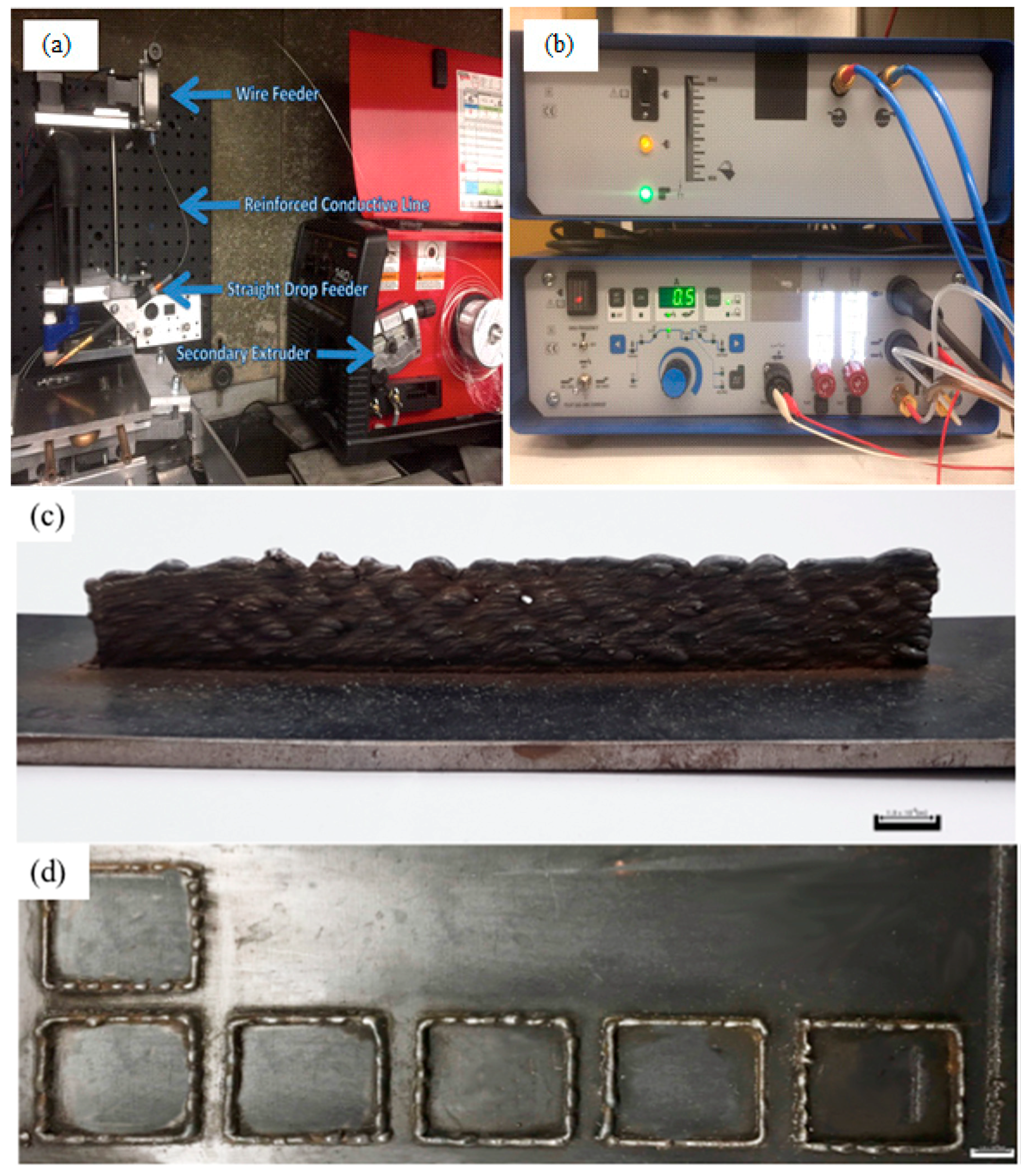
2.2. Experimental Setup

The first step in the creation of the WAAM equipment was the development of a motion control system. For this purpose, aluminum frames were used to allow the fabrication of relatively large and heavy components without compromising the structural integrity of the equipment. The system is capable to move in three axes (X, Y, and Z). Two different frames were created. The first one is used to control the movement of the printing platform in the X and Y axes. This frame is placed horizontally, directly over the horizontal plane. The printing bed is belt-driven by two 5V stepper motors (one for each axis). Each axis slides with the use of four barrel-bearings over two steel rods (two bearings per rod), to ensure smooth movement. To hold the substrate in place, a clamping system made from aluminum was created. The Z axis is controlled by an individual frame. A 12 V motor (used on a Lincoln Electric 140 c MIG welder (Lincoln Electric, Houston, TX, USA)) is used to feed wire. The system is controlled by a couple formed by an Arduino Mega 2650 board and a Ramps 1.4 board (JAMECO Electronics, Belmont, CA, USA). A modified version of the open source firmware Marlin (1.1, Ultimaker, Geldermalsen, NED) is used as operating environment (shown in Figure 1a).
A Pro-Fusion Dual Arc 82HFP (Elderfield & Hall, Knoxville, TN, USA) (see Figure 1b) welding machine was selected since it allows the precise control of the current intensity supplied to the system. In low current mode (from 0.1 to 20 Ampere) the parameter can be changed by increments of 0.1 Ampere. When working with higher currents (up to 80 Ampere) the steps become of 0.5 Ampere. The incorporation of “Pulsation Mode”, in which the current is supplied in alternating on-off intervals, has been found convenient for the reduction of heat affected zones while working with stainless steel. The machine is also equipped with a “High Frequency” option, in which the machine sends high frequency pulses through the electrode until a grounded conductive surface is detected. Once a suitable surface is found, an electric arc is automatically started, and the electrode stops emitting high frequency pulses. This mode is highly convenient while printing since the arc will not always remain on. Two different heat sources have been used in this project.
The created WAAM systems rely on the use of a plasma arc for the melting and fusing of a metallic wire (filler) and a printing bed (substrate). The wire is being fed by 12 V motor through a reinforced conduction line and delivered to the molten metal pool created by the arc. The wire and substrate fuse together while the printing bed moves, creating a 3D line. The final build is affected by several factors, including printing bed speed, wire diameter, arc current density, the position and speed of the wire being fed through. Adjacent lines can be created by directly overlapping the line already printed and the printing path of the new line. Also, lines can be printed upon previous weld lines in order to create 3D structures. WAAM has already proved with our previous work (see Figure 1c,d) that it can produce 3D structured metal. Figure 1c shows 3D structured stainless steel stacked up with 24 lines. Figure 1d shows square shape of 3D printed stainless steel.

2.3. Sample Preparation

A series of trials using different printing parameters were performed to determine ideal printing parameters. Parameters related with the intensity of the arc were first found by a trial-and-error method. It was found that one of the main factors that affect the quality of the line was the gas flow rate of the pilot arc. When the flow rate is low (<0.4 L/min) the arc was not able to melt the wire. On the other hand, high flow rates (>0.8 L/min) create a strong jet that carves the substrate and ejects the molten metal wire away from the molten pool. Thus, a medium pilot arc gas flow rate was used (0.6 L/min). A shielding gas flow rate of 12 L/min was used for all the trials, protecting the melting pool from the exposed air. For both the pilot gas and the shielding gas 99.99% Argon was used. The cross-section area of the selected wire’s diameter was 1.5 mm and 12 V motor was used. The minimum feed rate that the motor is capable to produce is 117 cm/min (46 in/min). This feed rate was then used for all the trials.
Samples were prepared at various arc currents and printing speed, keeping all other parameters constant. Table 3 shows a visual representation of the combination of parameters that were used on the trials to determine the best printing conditions. Printing speed was changed from 90 to 180 mm/min, using intervals of 15 mm/min between each trial. 20–50 Ampere were tried. This time, the intervals were kept on 5 A between each trial. A window of parameters in which visually uniform lines could be printed was found. 15 parameters inside this printing window were selected (5 current intensities; 30 A, 32.5 A, 35 A, 37.5 A, and 40 A, and 3 printing speeds 120 mm/min, 135 mm/min, and 150 mm/min). Using each one of these combinations, five parallel lines were printed over the same substrate. After printing, the lines were detached from the substrate and their dimensions were measured. The lines were sectioned and mounted in epoxy resin for further analysis and characterization. All the samples were wet ground through successive grades of silicon carbide abrasive papers from P240 to P4000 (Buehler, Lake Bluff, IL, USA) and etched with glycol (1 mL HNO3, 24 mL of water, 75 mL Ethylene Glycol) [20].

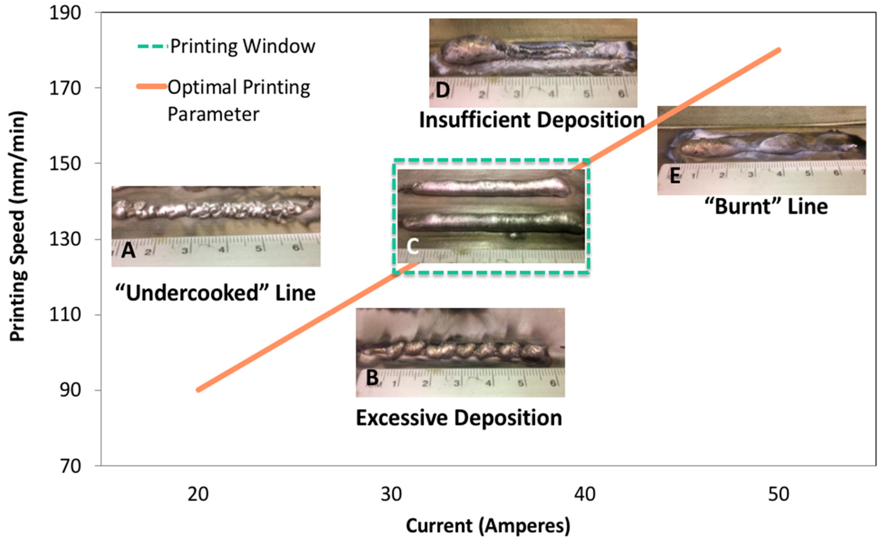
2.4. Experimental Design

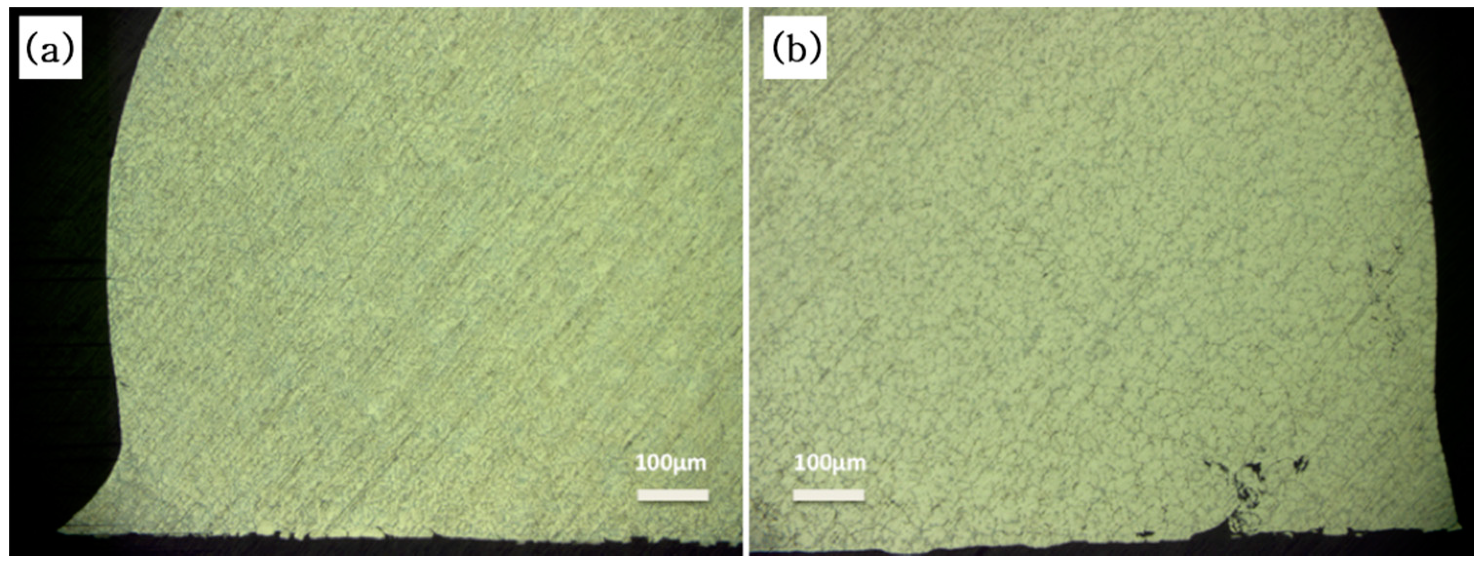
2.4.1. Optical Microscope

Micrographs of the magnesium wire as well as the WAAM produced samples were taken for visual comparison. Additional images were taken of WAAM samples after the corrosion test to identify any changes. The optical microscopes used for this project were Nikon and Eclipse LV15ONL (Nikon, Brighton, MI, USA) and KEYENCE VHX-900 Digital Microscope (KEYENCE, Itasca, IL, USA) equipped with a VH-Z100UR lens.

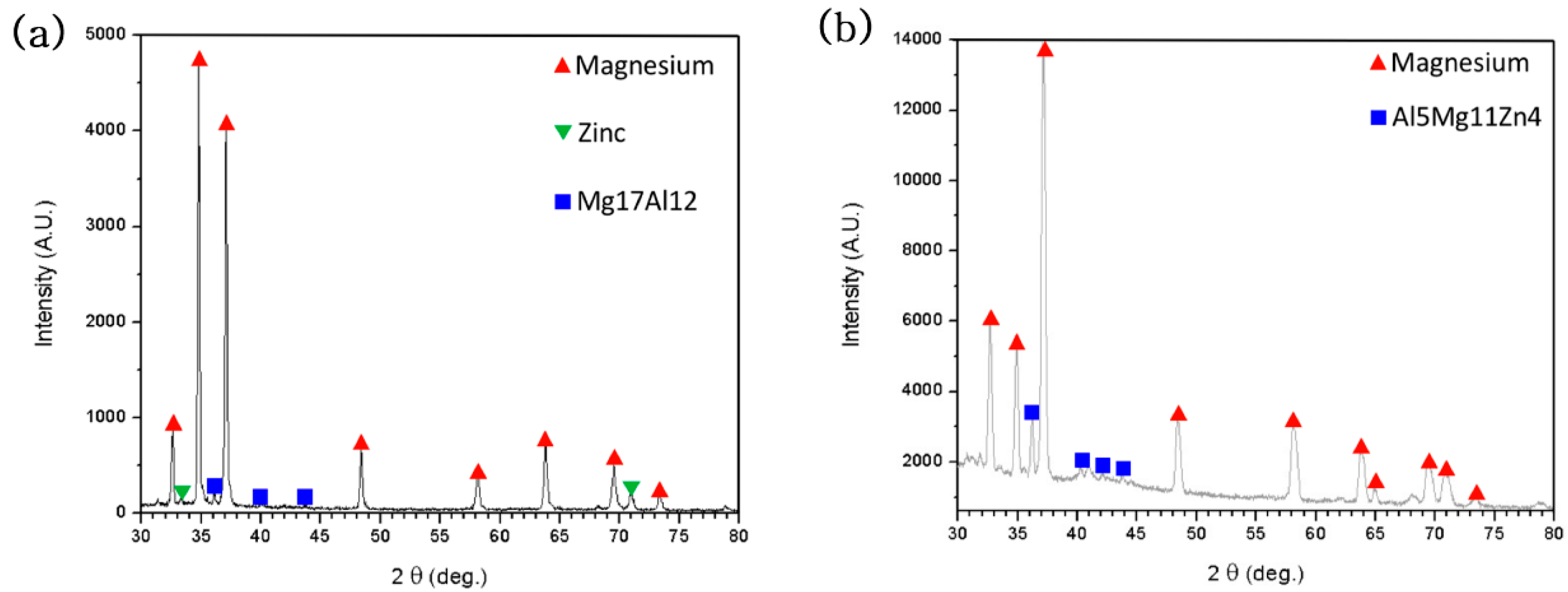
2.4.2. X-ray Diffraction (XRD)

A Bruker XRD D8 system (BRUKER AXS, Madison, WI, USA) using Cu K9 (l = 1.54 Å) X-ray source was used to for the analysis of the as-received wire and printed lines.

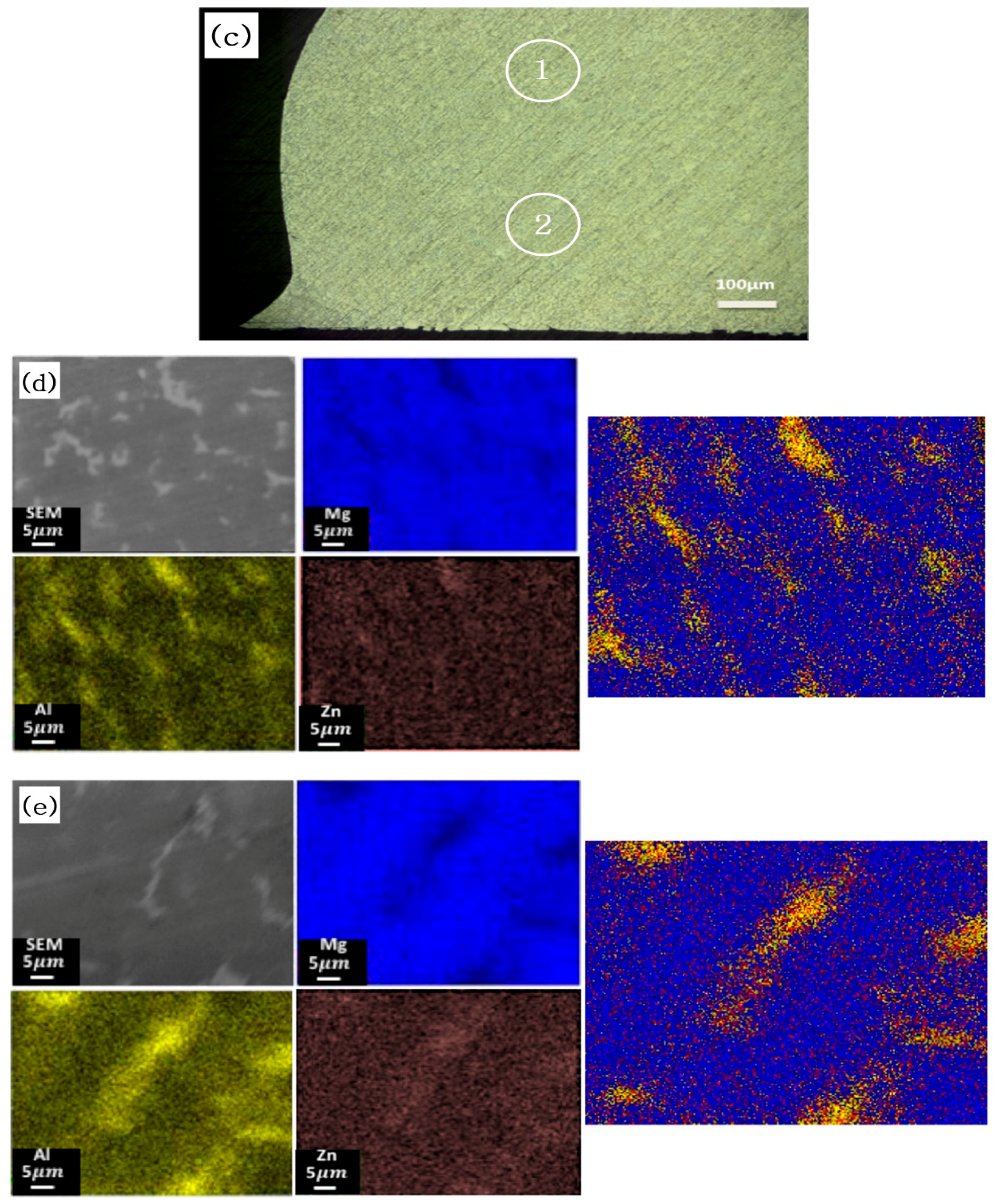
2.4.3. Scanning Electron Microscopy (SEM) and Energy Dispersive Spectroscopy (EDS)

The use of SEM was limited to obtaining reference images for EDS mapping. A Hitachi S4800 (Hitachi, Dallas, TX, USA) equipped with EDS was used. Two different areas of AZ91D produced by WAAM the cross-section area were analyzed (center and top). The accelerating voltage was 10 kV for all the cases.

2.4.4. Electrochemical Impedance Spectroscopy (EIS)

The Electrochemical Impedance Spectroscopy was carried out by using a computer controlled potentiostat (VersaSTAT 3F, AMETEK SI, Oak Ridge, TN, USA) with 3.5 wt % NaCl solution at room temperature. The experimental setup consisted of three electrode cell containing graphite as counter electrode, 3D printed sample as working electrode and saturated Ag/AgCl electrode (saturated with KCl, Accumet Glass Body (Fisher Scientific, Dallas, TX, USA)) was used as the reference electrode. Working electrodes, the electrical contact between a copper wire and the sample was made at the back of the sample with silver conductive epoxy. The whole assembly was protected from the solution by mounting it in epoxy resins, which makes it leave only one face of the electrode exposed to the solution. The exposed surface area was 0.77 cm2.

3. Results and Discussion

3.1. Sample Preparation

Figure 2 shows representative lines printed over a range of printing conditions. Low temperature conditions can be achieved by using fast moving speed and applying low arc current, such as in the case of condition A. In this case, it is noticeable that the wire did not completely melt. Traces of the original wire can be seen in many points of the line. When dealing with low currents (20–30 A) but low printing speeds, such as the case of condition B, mounds of fully molten metal can be seen. It is believed that the high amount of materials deposited due to the low speeds made created the partition of the original line. On the contrary cases, when high currents (>40 A) the metal wire becomes highly fluid. Thus, at printing speeds greater than 170 mm/min (condition D), the molten metal will flow and congregate on the beginning of the printed line, since it is the first solidified region. At lower speeds (<160 mm/min) the molten metal has more time for its solidification. For this reason, the molten metal will flow and conglomerate in those places where the liquid metal has become solid, as seen on conditions E. However, printing conditions in which mostly visually uniform lines was found which was the combination of medium arc currents (30–40 A) and relatively low printing speeds yielded the best results. C shows representative lines printed under conditions laying in this “printing window”.
Through printing, a decrease in the contact angle as a function of the heat conditions was detected. For all the printing parameters the wire feed rate remained constant. The flow rate of both the pilot arc and the shielding gas was also kept constant. Thus, only two out of the four parameters affecting the contact angle of the printed specimens were varied. First, the size of the weld pool, which is in direct correlation with the current intensity. Second, as the supplied current increases, more heat is delivered to the substrate, increasing the size of the molten pool. The printing speed of the build is based on the movement of the melting pool and not on the wire feed rate. The wire feed rate must be greater to allow enough material to melt and fuse to the plate. Also, by increasing the size of the molten pool (increasing current) the contact angle would decrease since the surface energy differential between the molten substrate and the depositing metal would be lower than that between a solid substrate and a liquid filler. Table 3 shows the heat input into the system depending on the printing conditions. Noticeable is the fact that the amount of heat delivered into the system is directly proportional to the arc current and inversely proportional to the printing speed, to calculate the heat input the following formula was used:
H e a t   I n p u t = A r c   V o l t a g e A r c   C u r r e n t T h e r m a l   E f f i c i e n c y T r a v e l   s p e e d
where arc voltage is 25 volts (constant for all the cases), thermal efficiency is 60% for PAW, arc current (Ampere) and travel speed (mm/s) are the variables [21].
Due to the relatively low melting point of magnesium and its alloys, remelting is a common problem when printing these materials [22]. Thus, as the temperature of the substrate increases because of the increasing number of lines printed over the same plate, the lines become more susceptible to remelting. It is believed that, along the increased size of the molten pool, remelting is a cause of the reduction of contact angle between the substrate and the printed line as more lines are printed over the same plate. Figure 3 shows two examples of lines presenting remelting. A change in contact angle is noticeable on the areas closest to the substrate. This indicates that heat coming from the printing plate was enough to melt part of the printed line.

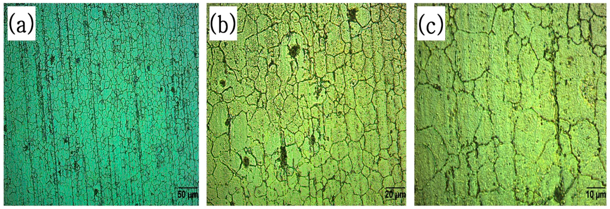
3.2. Microscopic Analysis

With the use of optical microscopy, the microstructure of the as received AZ91D wire was analyzed. Figure 4 shows a micrograph of a longitudinal cut of the feedstock. A fairly equiaxed grain appears on the micrograph. The presence of equiaxed grains indicates that the wire was rolled at high temperatures and then cooled by air. The slow heat dissipation inside the wire coil made possible conditions like those required for annealing, hence the final microstructure [23]. The presence of second phase particles aligned on the rolling direction can also be seen. The presence of defects was also detected.
Figure 5 shows a representative microscopy of a printed line, which demonstrates that the microstructure of the printed structure is considerably different than that of the AZ91D wire. High density of well-dispersed second phase particles can be seen in Figure 5a compared to Figure 4a. This microstructure is repeated for all the printed lines regardless the printing parameters or its number within the same printing plate. Both longitudinal and transversal directions show the same arrangement.
Based on the microscopic analysis, there is an assumption of a precipitate within the magnesium build. The precipitate is assumed to be Al5Mg11Zn4 based on previous work done within this research department. X-ray diffraction (XRD) confirmed the presence of the precipitate (see Figure 6a,b), while energy dispersive spectroscopy result approved the dispersion of the elements through the material. Figure 6c represents the two different sections where elemental mappings were taken and Figure 6d,e show the result of elemental mappings (see Figure 6d,e).

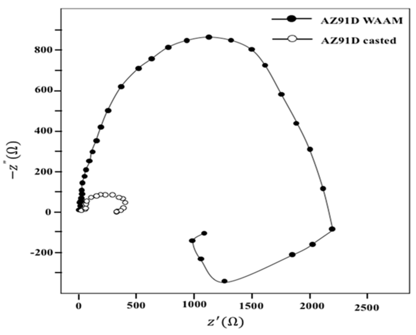
3.3. Electrochemical Impedance Spectroscopy (EIS)

EIS graph (see Figure 7) reveals a semi-circular form where its diameter is related to the composition and microstructure. Several authors have described this arc’s diameter being associated with corrosion resistance [25,26]. With that said, AZ91D produced by WAAM had six times larger diameter than the AZ91D produced by casting which means corrosion resistance of AZ91D produced by WAAM was better [27]. This result can be related to the new precipitates (Al5Mg11Zn4) and relieve the internal stress by using WAAM process.

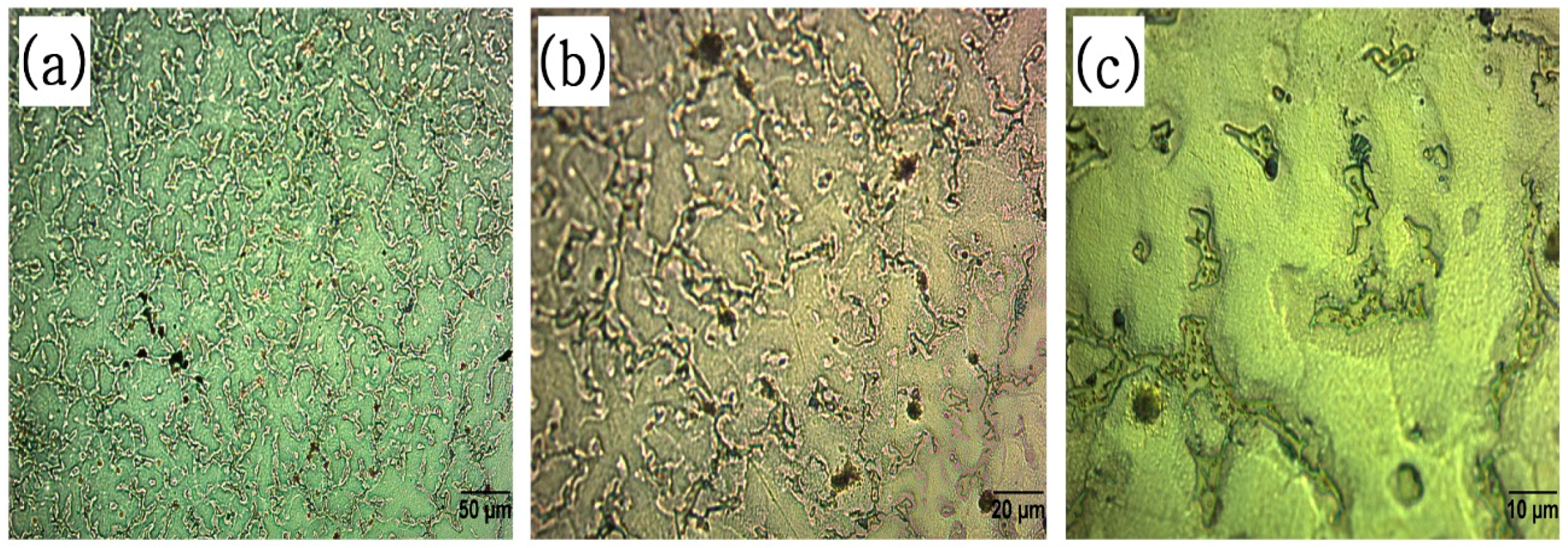
3.4. Microstructure after Corrosion

Figure 8 presents microscopic views of the corroded surface of the as-received wire AZ91D and AZ91D produced by WAAM. Figure 8a produced circular pits which initiated at the magnesium matrix (a phase). On the other hand, Figure 8b shows less pits than as-received wire. This is due to the well-dispersed second phase particles on the surface that act as a corrosion barrier to subsequent barrier.

4. Conclusions

In this research, it has been proven that magnesium alloy AZ91D can be used for the creation of specimens using WAAM systems. To obtain uniform base lines, the thermal gradient generated by the plasma arc must be reduced by controlling the movement of the printing bed. Furthermore, the orthorhombic phase present in the microstructure is not what is expected for this alloy. The shielding gas used for removing stagnant air also quenches the sample during the welding process. Zinc atoms are not able to migrate into the bulk crystal, forming Al5Mg11Zn4 precipitate. This precipitate formation has higher corrosion resistance than a cast magnesium sample.

Author Contributions

N.K. conceived and designed the experiments; S.H. designed and performed corrosion experiments; M.Z. contributed corrosion experiment and installed WAAM; D.M.H. designed and installed WAAM; M.M.P. analyzed the microscopic data.

Funding

This research was funded by [Korea Institute of Machinery & materials], grant number [CRC-15-03-KIMM].

Acknowledgments

This work was supported by (Korea Institute of Machinery & Materialrs; CRC-15-03-KIMM), and this research has emanated from grant SKU-UTEP 2011-0216.

Conflicts of Interest

The authors declare no conflict of interest.

References

  1. Rezwan, K.; Chen, Q.Z.; Blaker, J.J.; Boccaccini, A.R. Biodegradable and Bioactive Porous Polymer/Inorganic Composite Scaffolds for Bone Tissue Engineering. Biomaterials 2006, 27, 3413–3431. [Google Scholar] [CrossRef] [PubMed]
  2. Nájera, S.E.; Michel, M.; Kim, K.-S. 3D Printed PLA/PCL/TiO2 Composite for Bone Replacement and Grafting. MRS Adv. 2018, 1–6. [Google Scholar] [CrossRef]
  3. Niinomi, M.; Hattori, T.; Morikawa, K.; Kasuga, T.; Suzuki, A.; Fukui, H.; Niwa, S. Development of Low Rigidity β-Type Titanium Alloy for Biomedical Applications. Mater. Trans. 2002, 43, 2970–2977. [Google Scholar] [CrossRef]
  4. Ridzwan, M.I.Z.; Shuib, S.; Hassan, A.Y.; Shokri, A.A.; Ibrahim, M.N.M. Problem of stress shielding and improvement to the hip implant designs: A review. J. Med. Sci. 2007, 7, 460–467. [Google Scholar] [CrossRef]
  5. Lhotka, C.; Szekeres, T.; Steffan, I.; Zhuber, K.; Zweymüller, K. Four-Year Study of Cobalt and Chromium Blood Levels in Patients Managed with Two Different Metal-on-Metal Total Hip Replacements. J. Orthop. Res. 2003, 21, 189–195. [Google Scholar] [CrossRef]
  6. Staiger, M.P.; Pietak, A.M.; Huadmai, J.; Dias, G. Magnesium and Its Alloys as Orthopedic Biomaterials: A Review. Biomaterials 2006, 27, 1728–1734. [Google Scholar] [CrossRef] [PubMed]
  7. Witte, F.; Eliezer, A. Biodegradable Metals. In Degradation of Implant Materials; Eliaz, N., Ed.; Springer: New York, NY, USA, 2012; pp. 93–109. ISBN 978-1-4614-3941-7. [Google Scholar]
  8. Li, N.; Zheng, Y. Novel Magnesium Alloys Developed for Biomedical Application: A Review. J. Mater. Sci. Technol. 2013, 29, 489–502. [Google Scholar] [CrossRef]
  9. Witte, F.; Fischer, J.; Nellesen, J.; Crostack, H.; Kaese, V.; Pisch, A.; Beckmann, F.; Windhagen, H. In vitro and in vivo Corrosion Measurements of Magnesium Alloys. Biomaterials 2006, 27, 1013–1018. [Google Scholar] [CrossRef] [PubMed]
  10. Levesque, J.; Dube, D.; Fiset, M.; Mantovani, D. Investigation of Corrosion Behaviour of Magnesium Alloy AM60B-F under Pseudo-Physiological Conditions. Mater. Sci. Forum 2003, 424–426, 521–526. Available online: https://www.cheric.org/research/tech/periodicals/view.php?seq=1254436 (accessed on 16 July 2018). [CrossRef]
  11. Xin, Y.; Liu, C.; Zhang, X.; Tang, G.; Tian, X.; Chu, P.K. Corrosion Behavior of Biomedical AZ91 Magnesium Alloy in Simulated Body Fluids. J. Mater. Res. 2007, 22, 2004–2011. [Google Scholar] [CrossRef]
  12. Gao, M.; Wei, R.P. A ‘Hydrogen Partitioning’ Model for Hydrogen Assisted Crack Growth. Metall. Trans. A 1985, 16, 2039–2050. [Google Scholar] [CrossRef]
  13. Regev, M.; Aghion, E.; Rosen, A.; Bamberger, M. Creep Studies of Coarse-Grained AZ91D Magnesium Castings. Mater. Sci. Eng. A 1998, 252, 6–16. [Google Scholar] [CrossRef]
  14. Wong, K.V.; Hernandez, A. A Review of Additive Manufacturing. ISRN Mech. Eng. 2012, 2012, 1–10. [Google Scholar] [CrossRef] [Green Version]
  15. Frazier, W.E. Metal Additive Manufacturing: A Review. J. Mater. Eng. Perform. 2014, 23, 1917–1928. [Google Scholar] [CrossRef] [Green Version]
  16. Han, K.N.; Kim, N.S. Challenges and Opportunities in Direct Write Technology Using Nano-Metal Particles. KONA Powder Part. J. 2009, 27, 73–83. [Google Scholar] [CrossRef]
  17. Amert, A.K.; Oh, D.-H.; Kim, N.-S. A Simulation and Experimental Study on Packing of Nanoinks to Attain Better Conductivity. J. Appl. Phys. 2010, 108, 102806. [Google Scholar] [CrossRef]
  18. Kim, N.S.; Han, K.N.; Church, K.H. Direct Writing Technology for 21th Century Industries—Focus on Micro—Dispensing Deposition Write Technology. In Proceedings of the Korean Society of Machine Tool Engineers Spring Conference 2007, Seoul, Korea, 14–19 May 2007. [Google Scholar]
  19. Taminger, K.M.B.; Hafley, R.A. Electron Beam Freeform Fabrication: A Rapid Metal Deposition Process. In Proceedings of the 3rd Annual Automotive Composites Conference, Troy, MI, USA, 9–10 September 2003. [Google Scholar]
  20. George, B.; Voort, V. Metallography of Magnesium and Its Alloys. Buehler Tech-Notes 2015, 4, 1–5. [Google Scholar]
  21. Huo, H.; Li, Y.; Wang, F. Corrosion of AZ91D Magnesium Alloy with a Chemical Conversion Coating and Electroless Nickel Layer. Corros. Sci. 2004, 46, 1467–1477. [Google Scholar] [CrossRef]
  22. West, E.G. The Welding of Non-Ferrous Metals, 1st ed.; John Wiley & Sons: New York, NY, USA, 1951. [Google Scholar]
  23. Humpherys, F.J. Recrystallization and Related Annealing Phenomena, 1st ed.; Elsevier B. V.: Kidlington, Oxford, UK, 1995. [Google Scholar]
  24. Martinez, D.A.; Han, S.; Kim, N.P. Magnesium Alloy 3D Printing by Wire and Arc Additive Manufacturing (WAAM). MRS Adv. 2018, 1–6. [Google Scholar] [CrossRef]
  25. Cao, C.-N. On the Impedance Plane Displays for Irreversible Electrode Reactions Based on the Stability Conditions of the Steady-State—I. One State Variable besides Electrode Potential. Electrochim. Acta 1990, 35, 831–836. [Google Scholar] [CrossRef]
  26. Cao, C.-N. On the Impedance Plane Displays for Irreversible Electrode Reactions Based on the Stability Conditions of the Steady-State—II. Two State Variables besides Electrode Potential. Electrochim. Acta 1990, 35, 837–844. [Google Scholar] [CrossRef]
  27. Pardo, A.; Merino, M.C.; Coy, A.E.; Viejo, F.; Arrabal, R.; Feliú, S. Influence of Microstructure and Composition on the Corrosion Behaviour of Mg/Al Alloys in Chloride Media. Electrochim. Acta 2008, 53, 7890–7902. [Google Scholar] [CrossRef]
Figure 1. Experimental setup: (a) Overall system for WAAM; (b) pro-Fusion Dual Arc 82HFP welding machine used a power supply; (c,d) stainless steel produced by WAAM (scale bar represents 1 cm).
Applsci 08 01306 g001
Figure 2. Visual representation of the macroscopically appearance of printed lines created under different printing conditions.
Applsci 08 01306 g002
Figure 3. Micrographs of two printed lines presenting a decrease in the contact angle due to re-melting: (a) Left side of printed line; (b) Right side of printed line (Eclipse LV15ONL and KEYENCE VHX-900 Digital Microscope).
Applsci 08 01306 g003
Figure 4. Optical micrograph of a longitudinal cot of the as-received AZ91D wire at: (a) 20×; (b) 50×; (c) 100×.
Applsci 08 01306 g004
Figure 5. Representative microstructure of printed lines. Al5Mg11Zn4 precipitate (j phase) embedded on a Mg matrix (a phase). (a) 20×; (b) 50×; (c) 100×.
Applsci 08 01306 g005
Figure 6. (a) XRD spectra of as-received wire, representative peaks of magnesium (a phase), zinc, and Mg18Al13 precipitates (b phase); (b) XRD spectra of a representative printed line, representative peaks of pure magnesium (a phase) and Al5Mg11Zn4 precipitates (j phase); (c) representing the areas from which the elemental mappings were taken; (d) Elemental Mapping of zone 1 [24]. Copyright 2018, Cambridge University Press; (e) Elemental Mapping of zone 2 [24].
Applsci 08 01306 g006aApplsci 08 01306 g006b
Figure 7. EIS results of AZ91D WAAM and AZ91D casted [27] 3.5 wt % NaCl. Copyright 2008, Elsevier.
Applsci 08 01306 g007
Figure 8. After corrosion microstructure of AZ91D produced by WAAM and casting: (a,c) AZ91D casted; (b,d) AZ91D WAAM.
Applsci 08 01306 g008
Table 1. Mechanical properties of steels and bone. Reproduced from [6]. Copyright 2006, Elsevier.
DensityElastic Modulus (GPa)Compressive Strength (MPa)Fracture Toughness (MPa/m2)
Natural Bone1.8–2.13–20130–1803–6
Ti alloy4.4–4.5110–170758–111755–115
Co-Cr Alloy8.3–9.2230450–1000N/A
Stainless Steel7.9–8.1189–205170–31050–200
Magnesium1.74–2.041–4564–10015–40
Table 2. Chemical composition of magnesium alloy AZ91D. Reproduced from [14]. Copyright 1998, Elsevier.
ElementWt %
Al8.5–9.5
Zn0.45–0.9
Si0.05 max
Mn0.17 max
Cu0.015 max
Fe0.004 max
Ni0.001 max
Other0.01 max
MgBalance
Table 3. Combination of parameters during printing.
Current (Ampere)Printing Speed (mm/min)Heat Input (kJ/mm)
301200.225
301350.200
301500.180
32.51200.244
32.51350.217
32.51500.195
351200.263
351350.233
351500.210
37.51200.281
37.51350.250
37.51500.225
401200.300
401350.267
401500.240

