Article

Fluid Flow Characteristics and Weld Formation Quality in Gas Tungsten Arc Welding of a Thick-Sheet Aluminum Alloy Structure by Varying Welding Position

1
State Key Laboratory of Tribology, Department of Mechanical Engineering, Tsinghua University, Beijing 100084, China
2
Tianjin Long March Launch Vehicle Manufacturing Co., Ltd., Tianjin 300462, China
*
Author to whom correspondence should be addressed.
Appl. Sci. 2018, 8(8), 1215; https://doi.org/10.3390/app8081215
Submission received: 7 May 2018 / Revised: 8 July 2018 / Accepted: 20 July 2018 / Published: 24 July 2018

Abstract

:
This study aims to reveal the cause of different weld formation quality for varying welding position in the GTAW (Gas Tungsten Arc Welding) of a thick-sheet aluminum alloy structure. The fluid flow characteristics of weld pools are investigated by CFD (Computational Fluid Dynamic) modeling and high-speed imaging for the climbing and flat welding positions, which correspond to the start and finish ends of the welds of the structure, respectively. Results show that the directions of gravity relative to weld pools may notably affect the fluid flows in weld pools for different welding positions. For flat welding, gravity will accelerate the fluid flow in the direction of sheet thickness only and in turn result in a high velocity downwards, which implies a good penetrating capability. Welds of good formation with smooth surface and consistent width can be produced under flat welding position. In contrast, for climbing welding, gravity will act on the molten metal in both the direction of sheet thickness and the lateral direction of the weld pool. As a result, the velocity in sheet-thickness direction is decreased, which implies a decreased penetrating capability. Meanwhile, the velocity backwards is increased in the top portion of the weld pool, which makes the molten metal apt to flow out of the weld pool. Both the decreased penetrating capability and the accelerated molten metal outflow would render the climbing welding process unstable, and result in welds of poor formation with uneven weld surface and inconsistent weld width. Based on the study, possible methods are proposed that could be used to improve the weld formation quality when welding thick-sheet aluminum alloys structures using various welding positions.

1. Introduction

Aluminum alloys have been widely used in manufacturing aeronautical and aerospace structures thanks to their high specific strengths and moderate cost. Gas tungsten arc welding (GTAW) is one of the main welding processes employed in welding such structures of aluminum alloys, within which complex three-dimensional (3D) weld paths may exist [1,2]. In GTAW of such 3D welds, it is often impractical to realize and maintain the conventional flat welding position by manipulating the structures for fixed arc because of their large dimensions and/or weights. Instead, the posture of the welding torch is manipulated during welding according to the trajectory of a weld path while the structure is fixed and welded. Under such conditions, other welding positions, besides the flat welding position, are inevitable. However, it has been found that weld formation defects, such as poor bead surface appearance, inconsistent width and depth, undercuts, etc. are more apt to occur for welding positions (e.g., vertical welding) other than the flat position. This becomes even more serious when the aluminum alloy sheets are thick (with thickness greater than 5.0 mm) [3]. The welds with poor formation quality need be repaired, or even scraped when the defects are too serious, which then lead to increase in cost and waste of materials. Hence, it is imperative to investigate the causes and possible solutions to the poor weld formation in the GTAW of a thick-sheet aluminum alloy structure using varying welding positions.
As we know, the weld formation is closely related to the fluid flow behavior of molten metal in weld pools [4,5], which can be affected by the welding positions taken during welding. The horizontal welding position has been demonstrated to be more effective than flat welding position in reducing the weld formation defects of undercut and sagging when welding a thick high strength steel by laser beam [6]. This was attributed to the more desirable fluid flow state for the horizontal weld pool that resulted from the joint action of surface tension, recoiling pressure and gravity [7]. In contrast, in laser welding of Ti6Al4V titanium alloy, the flat welding position led to better weld profiles than the horizontal welding position, in terms of weld undercut, excess weld metal, and excess penetration [8]. In addition, for vertical welding positions, the undercuts of vertical up welds were greater than that of vertical down welds for the same welding parameters. Burn-through holes and inconsistent weld bead widths were formed in vertical up welds, which were absent in vertical down welds. All these phenomena were believed resulted from the different actions of gravity on the weld pool metals for different welding positions [9]. For gas metal arc welding (GMAW) of thick steel plates, it has been revealed through both numerical modeling and experimental observation that the welding positions (flat, overhead, and vertical) could significantly affect the fluid flow behavior and free surface profile of weld pools, which in turn result in different weld formation quality, in terms of humping, overflow, etc., due to the action of gravity [10,11,12,13]. Numerical modeling by Zacharia et al. [14] indicated that completely different flow patterns might result from the different orientations of specimens in GTAW of the 6061 aluminum alloys. Studies by Kang et al. [15,16] showed that the gravitational orientation could considerably influence the solidification microstructures in terms of the primary dendrite spacing in GTAW of an Al-Cu alloy. Despite existing research carried out on the influence of welding position on the welding quality in welding of steel and titanium alloys via laser and GMAW welding processes, no research has been reported so far on the characteristics of fluid flow behavior for different welding positions and their relationship with the weld formation quality in GTAW of thick aluminum alloy sheets.
In this paper, numerical modeling and experimental observations are carried out to investigate the fluid flow behavior of molten metal in weld pools, to reveal the cause and propose possible solutions to the poor weld formation in GTAW of a thick-sheet aluminum alloy structure with varying welding position.

2. Research Methodology

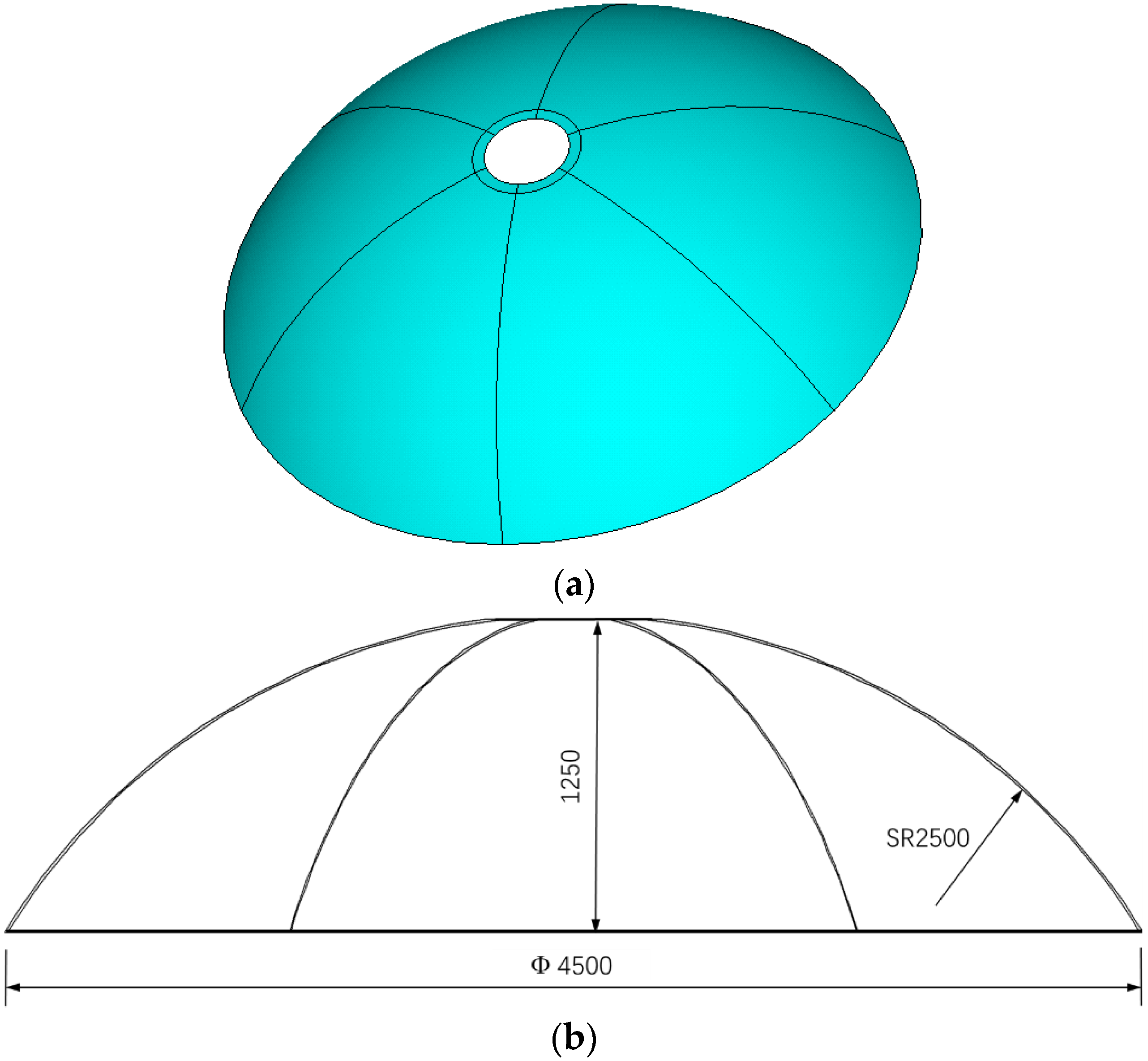
2.1. Structure and Materials

The aluminum alloy structure of this study is a section of spherical shell, as shown in Figure 1, which is manufactured by butt-welding six smaller pieces of melon petals to each other. The structure is made of 2219 aluminum alloy sheets with a thickness of 9.5 mm, of which the chemical composition is listed in Table 1.
Each of the six welds in the structure is completed through two weld passes using the GTAW process. The first is the root pass without filler wire and bottom backing, and with helium as the shielding gas; the second is the cap pass made using a filler wire with the same composition as the base metal aluminum alloy, and with argon as the shielding gas.
Because the structure is huge (about 5 m in diameter), it is unpractical to rotate it to maintain a flat welding position that is generally adopted when welding such structures because of the extremely high power demands and poor positioning precision. Instead, the structure is fixed while the welding arc moves from the start (bottom) to the finish (top) ends of a weld, as shown in Figure 2. In this way, the welding position keeps changing during the welding process. At the start end, a climbing welding position is assumed, which lies between the vertical up and flat welding positions, while, at the finish end, it is basically the flat welding position. In practice, it has been found that the poor weld formation mainly occurs at the starting end but not at the finish end during the root pass welding. Therefore, this paper aims mainly to study the formation quality and the fluid flow characteristics at these two extreme ends, i.e., climbing and flat welding positions, when welding the thick aluminum structure.

2.2. CFD Analysis

2.2.1. Computational Model

Computation fluid dynamics (CFD) software ANSYS Fluent (version 13.0) was used in this study to simulate the root pass GTAW process of the spherical shell ring structure, and the fluid flow characteristics of molten metal in weld pools were investigated for the climbing and the flat welding positions shown in Figure 2.
Considering the diameter of the shell structure (about 5 m) is much larger than its thickness (9.5 mm), the welding processes at both start and finish ends of the panel sheets were simplified as butt welding of flat sheets, i.e., the curvature of sheets was neglected in modeling. Moreover, the top and bottom surfaces of the weld pools were assumed to be flat and not deformable in simulations, as the existing studies showed that such a simplified model could still be used effectively to reveal the correlations between the weld formation and the fluid flow [6].
A tungsten arc is fixed at a position above the top surface of a workpiece, while the workpiece moves at the welding speed being used, as shown in Figure 3. In addition, as the workpieces and heat source (welding arc) are symmetrical about the central plane of a butt joint, only one half of the weld joint was included in the numerical model. The dimensions of the computation domain are 50 × 25 × 9.5 mm3, and the minimum cell in the model is 1.0 × 1.0 × 0.95 mm3. A mesh-independency study was performed, in which a one-half smaller mesh (0.5 × 0.5 × 0.475 mm3) was also used. The differences in the results from two meshes were within 1.5%, indicating the mesh used in the study was fine enough.

2.2.2. Governing Equations

Fluid flow in the molten metal is assumed to be Newtonian, incompressible and laminar. The two phases (solid and liquid) are solved in a single computational domain. The governing equations describing the heat and mass transfers during the gas tungsten arc welding processes are as follows:
The continuity equation:
  ρ t + ( ρ u ) x + ( ρ v ) y + ( ρ w ) z + S m = 0  
The momentum equation, in the x axis:
  ( ρ u ) t + ( ρ u u ) x + ( ρ v u ) y + ( ρ w u ) z = x ( μ u x ) + y ( μ u y ) + z ( μ u z ) P x + S x  
The momentum equation, in the y axis:
  ( ρ v ) t + ( ρ u v ) x + ( ρ v v ) y + ( ρ w v ) z = x ( μ v x ) + y ( μ v y ) + z ( μ v z ) P y + S y  
The momentum equation, in the z axis:
  ( ρ w ) t + ( ρ u w ) x + ( ρ v w ) y + ( ρ w w ) z = x ( μ w x ) + y ( μ w y ) + z ( μ w z ) P z + S z  
The energy equation:
  ( ρ H ) t + ( ρ u H ) x + ( ρ v H ) y + ( ρ w H ) z = x ( k T x ) + y ( k T y ) + z ( k T z ) + S H  
where u ,   v and w are the components of velocity in three directions; ρ ,   P ,   H ,   k and μ denote the density, pressure, enthalpy, thermal conductivity and viscosity, respectively; and S m ,   S x ,   S y ,   S z and S H denote the source terms of the continuity equation, momentum equations, and energy equation, respectively. In the present study, S m is zero because the mass interchange between the computational zone and the environment is negligible in the GTAW welding process. The source terms for the energy equation and the momentum equations are detailed below.

2.2.3. Boundary Conditions
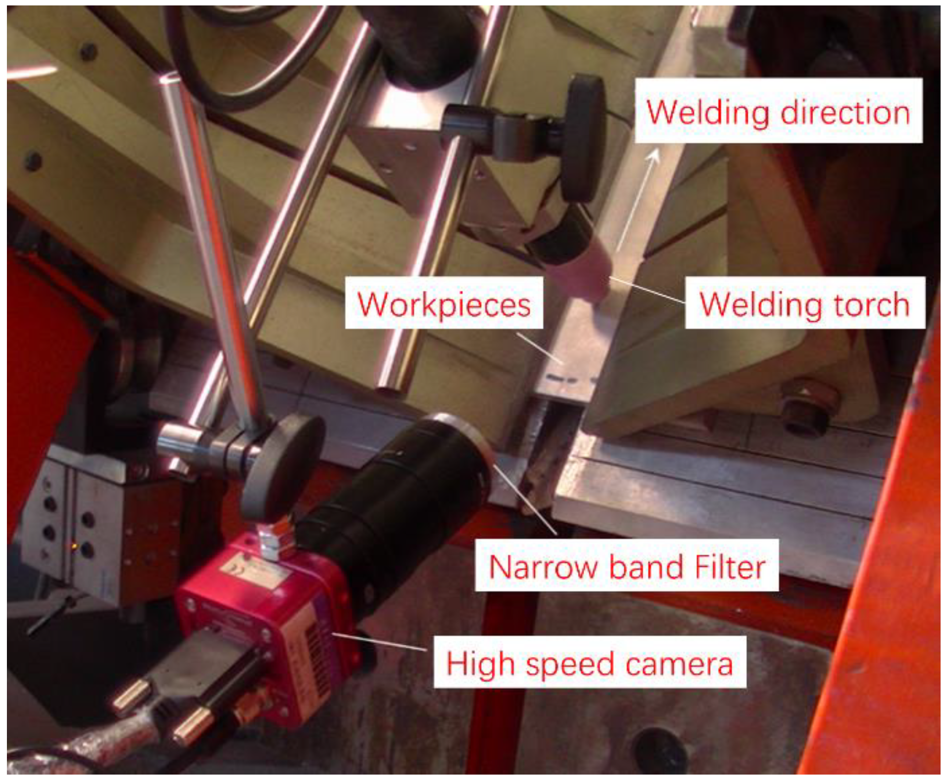
(1) Thermal boundary conditions
In GTAW welding process, the two workpieces to weld are first melted locally under the heat input from the welding arc between the tungsten electrode tip and the workpieces, and then the molten metals solidify to form a weld that joins the workpieces together. In the simulation, the heat input from the welding arc was modeled using a Gaussian body heat source, in which the heat flux took a Gaussian distribution in radial direction, while the peak heat flux diminished linearly in sheet thickness direction. The expression of the heat input is as follows [17]:
  q ( r , z ) = ( 1 z 2 h ) 4 Q η π h r 0 2 exp ( 3 r 2 r 0 2 )  
where q is the heat flux (W/mm3) of heat source, r is the distance to the center of heat source, r0 is the radius of the heat source, z is the coordinates in sheet thickness direction, h is the sheet thickness, Q is the output power of the power source (i.e., product of electric current I and electric voltage V), and η is the thermal efficiency. The values of the parameters used in simulation are listed in Table 2.
Forced convection boundary conditions were applied on the regions of top and bottom surfaces in contact with the fixture, while natural convection boundary conditions were applied on the surfaces exposed to the environment. The convection coefficients used in simulation are also given in Table 2.
(2) Arc pressure
The arc is not only a heat source to melt metals, but also a pressure source in GTAW, which may affect the movement of molten metals in the weld pool. A Gaussian distribution of the arc pressure was assumed in the study as follows [18,19]:
  P ( r ) = 3 μ 0 I 2 4 π 2 r p 2 exp ( 3 r 2 r p 2 )  
In Equation (2), μ 0 is space permeability, I is the welding current, r is the distance to the arc center, and rp is the radius of pressure source.
(3) Surface tension
The dependence of surface tension of molten metal on temperature for the 2219 aluminum alloy was assumed to obey the expression [20]:
σ = 0.914 − 0.35 × 10⁻³ × (T − 930)
where T is the temperature in Kelvin. In the CFD modeling, to account for the effect of Marangoni stress on the fluid flow of molten metal in weld pools, the thermal gradient of the surface tension was set to be −0.35 × 10⁻³ N/(m⋅K).
(4) Gravity
With the numerical models established, the welding processes under climbing and flat welding positions were numerically studied. Different welding positions were realized by changing the directions of gravity action relative to the orientation of workpieces. For flat welding, the gravitational acceleration (g) is totally in the minus z direction, while, for climbing welding, the gravity has two components, i.e., gx and gz, in the minus x and minus z directions, respectively.

2.3. Experiments

Experiments were also carried out to study the weld bead formation quality in GTAW of the 9.5 mm thick 2219 aluminum alloy sheets, in which butt welds of 200 mm long were produced at the start and the finish ends of the shell structure, respectively. The dimensions of the produced workpieces were 200 × 200 × 9.5 mm3. Meanwhile, high speed imaging system was employed to observe the weld pools. Figure 4 shows the equipment setup used in this study.
A Swiss made Photonfocus MV-D1024E-160CL high-speed camera was used in experiments, which was fixed to the welding torch and monitored the weld pools on line from behind. A band pass filter was employed to diminish the interference from electric arc light. The filter of type FB660-10 from Thorlabs was fixed in front of the high speed camera lens, of which the central wavelength was 660 nm and the full width at half maximum was 10 nm. A resolution and frame rate of 512 × 256 pixels and 250 fps were used, respectively. The videos recorded were processed and analyzed to validate the CFD model being developed, as well as to study the dynamic variations of weld pool dimensions during welding. Table 3 lists the process parameters used in the experiments.

3. Results

3.1. CFD Simulation Results

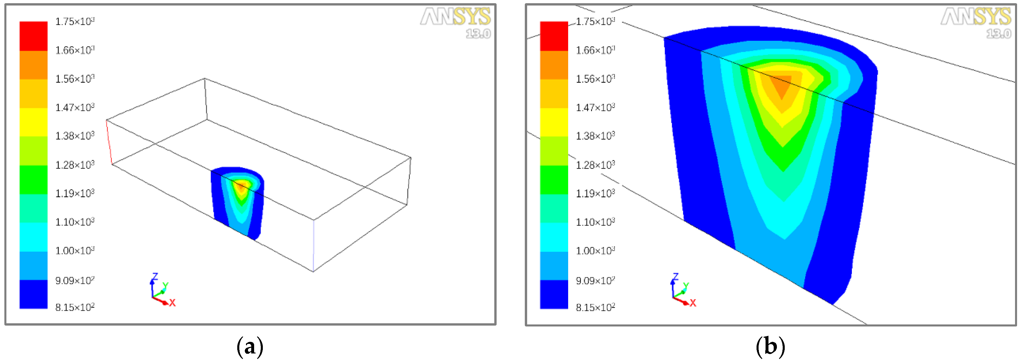
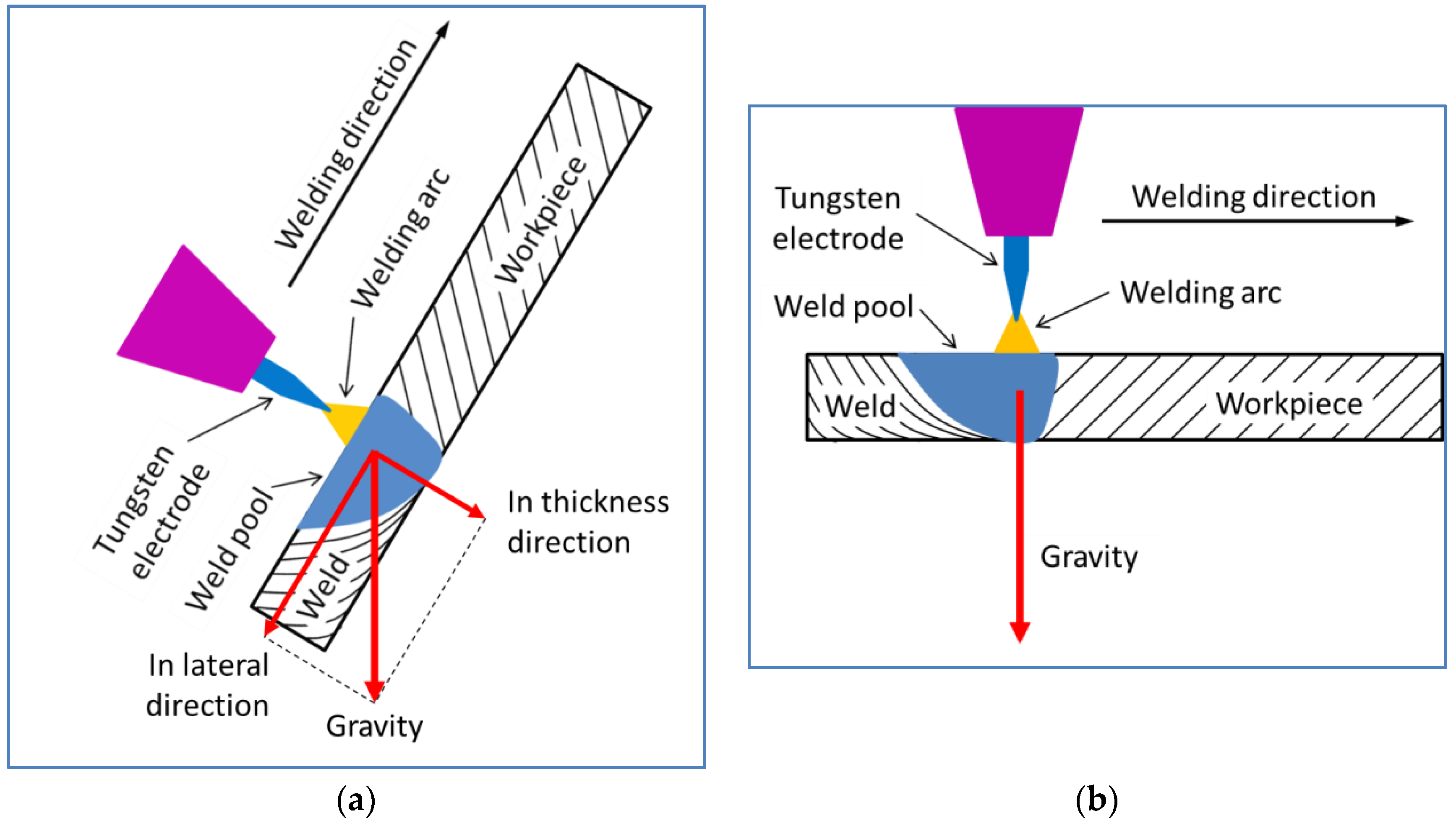
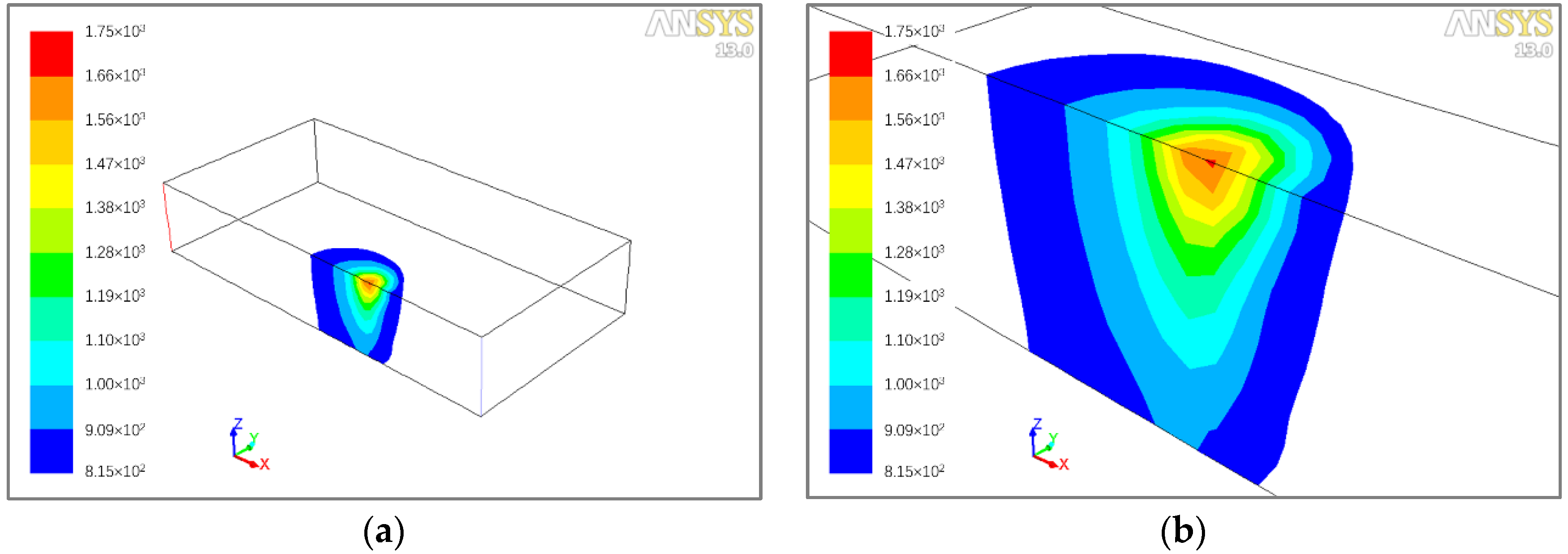
3.1.1. Temperature Fields for Different Welding Positions

The weld pools, i.e., the regions with temperatures above the melting point of the 2219 aluminum alloy (815 K), for flat (finish) position and climbing (start) position are shown in Figure 5 and Figure 6, respectively, after the welding processes have reached the quasi-steady state. For a better comparison, Table 4 lists the dimensions of the weld pools numerically predicted for the flat and the climbing welding positions. It can be found that, for both welding positions, the width and length of the top surface of the weld pool are slightly larger than those of the bottom surface. The temperatures on the top portion of the weld pool under the climbing welding condition (with a maximum temperature of 1678 K) are a bit higher than that with flat position (with a maximum temperature of 1653 K), which result in larger length and width of the top surface for the climbing weld pool than the flat weld pool. The changes in the length and width of the bottom surface of the weld pool are not as significant as top surface when the welding positions are changed, although a reduced high temperature region (with temperatures greater than 909 K) can be noted. As a result, the dimensions of the top surface of the weld pool are more notably larger than that of the bottom surface for climbing welding, as shown in Figure 7. From the figure, it can also be found that the climbing weld pool lags a short distance (about 1.5 mm) behind the flat weld pool due to the different gravity actions for different welding positions.

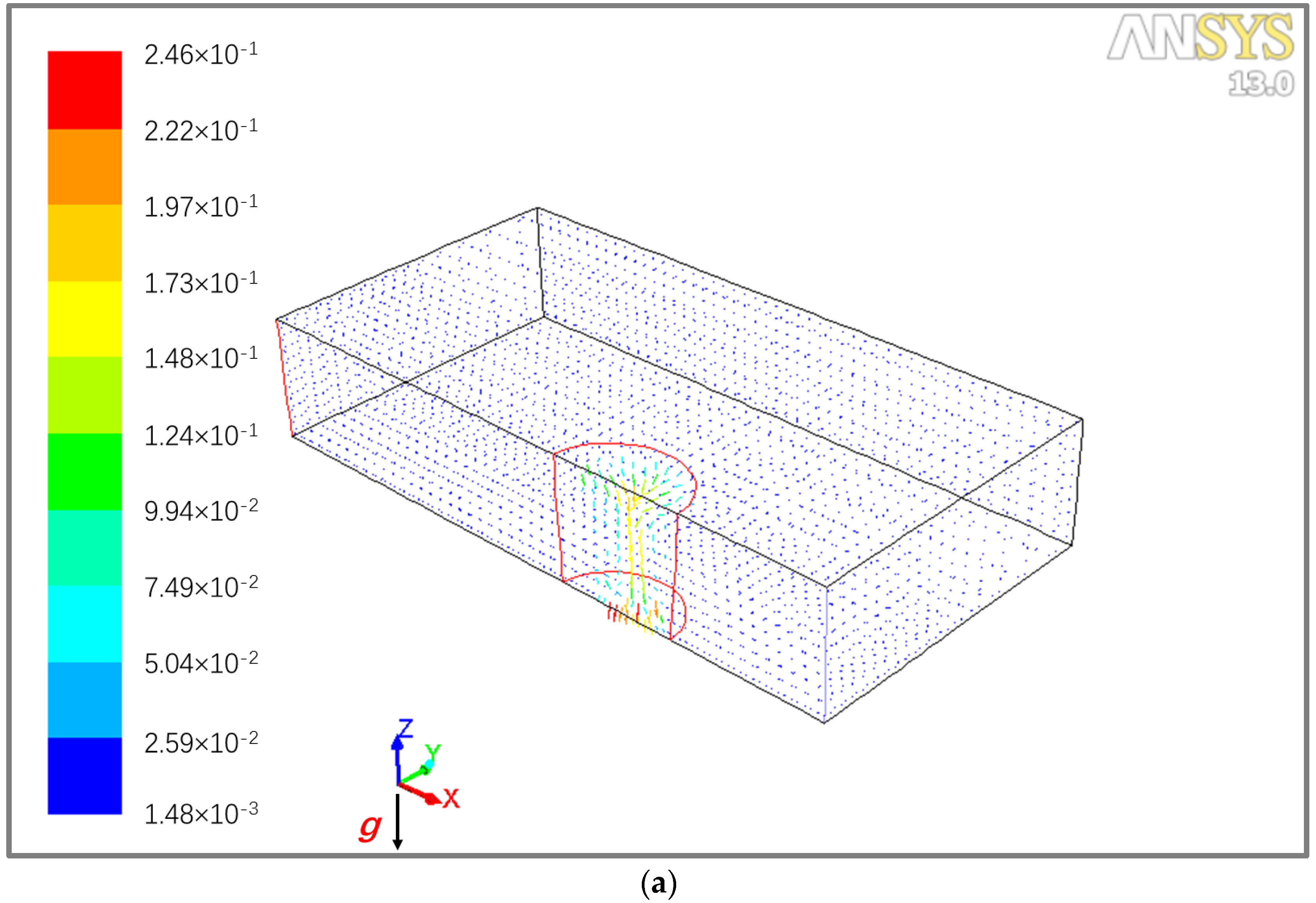
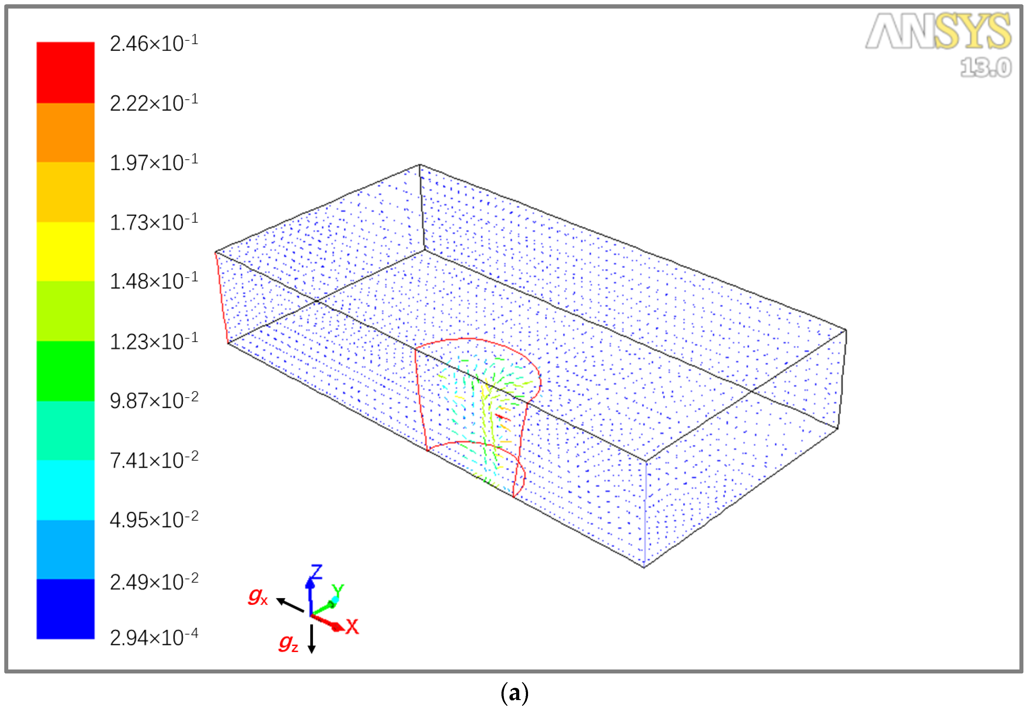
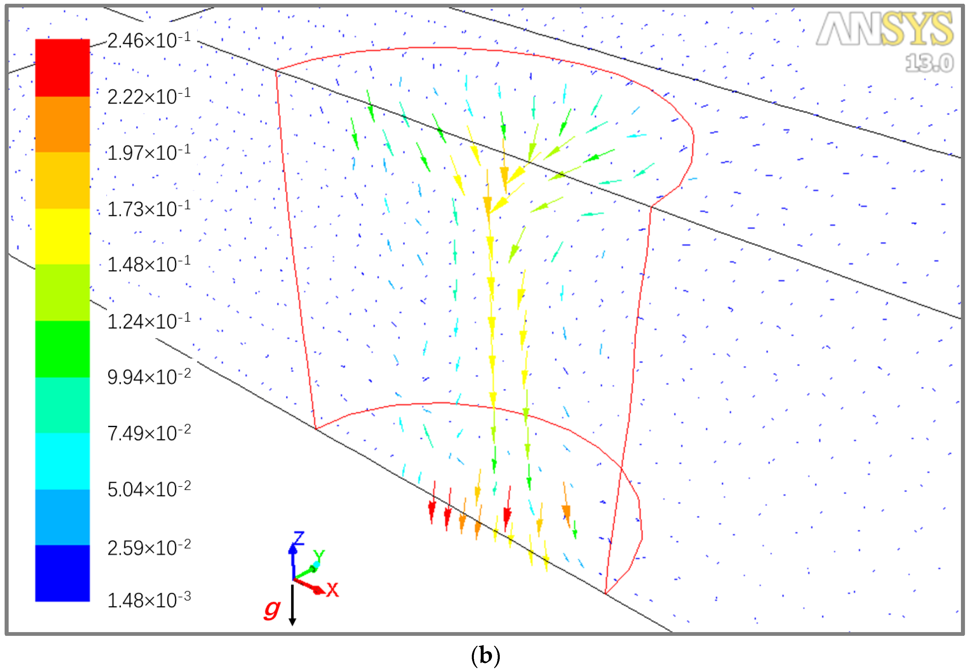
3.1.2. Velocity Fields under Different Welding Positions

The velocity fields for the flat welding position and the climbing welding position are shown in Figure 8 and Figure 9, respectively, when the welding processes have reached the quasi-steady state.
For the flat welding position, there exist high velocities downwards at the central part of the weld pool, which indicates the molten metal flows appreciably in thickness direction under the joint action of surface tension, gravity and arc pressure. Obviously, such a flow pattern is favorable to the increase in weld depth, while too significant downward fluid flow may result in defects such as excessive weld sagging and burn-through holes, and therefore should be avoided.
Compared to the flat welding, the fluid flow in the sheet thickness direction is weakened when welding with the climbing position, while the fluid flow afterwards (in –x direction), or in the lateral direction, is reinforced under the action of gravity. The velocity is the maximum in the lateral direction afterwards, indicating the fluid flow is the more significant in this direction than that in the sheet thickness direction for the welding conditions studied. Such a flow pattern leads to a longer and wider top surface of weld pool and shift the weld pool slightly behind the flat case, as shown in the preceding figures.

3.2. Experimental Results

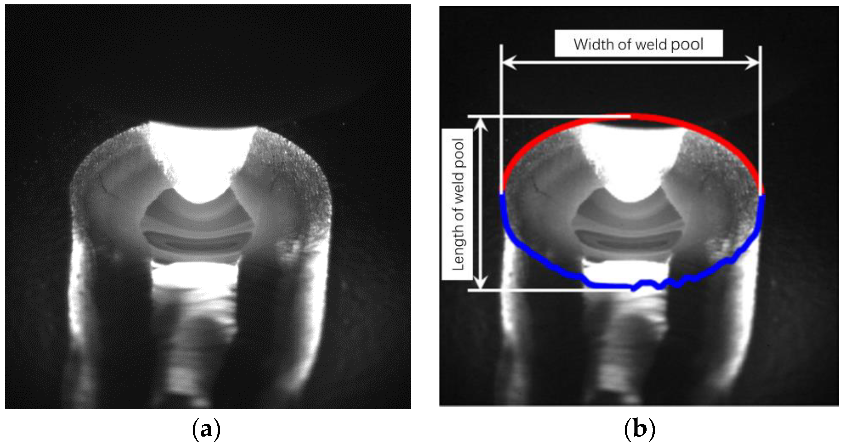
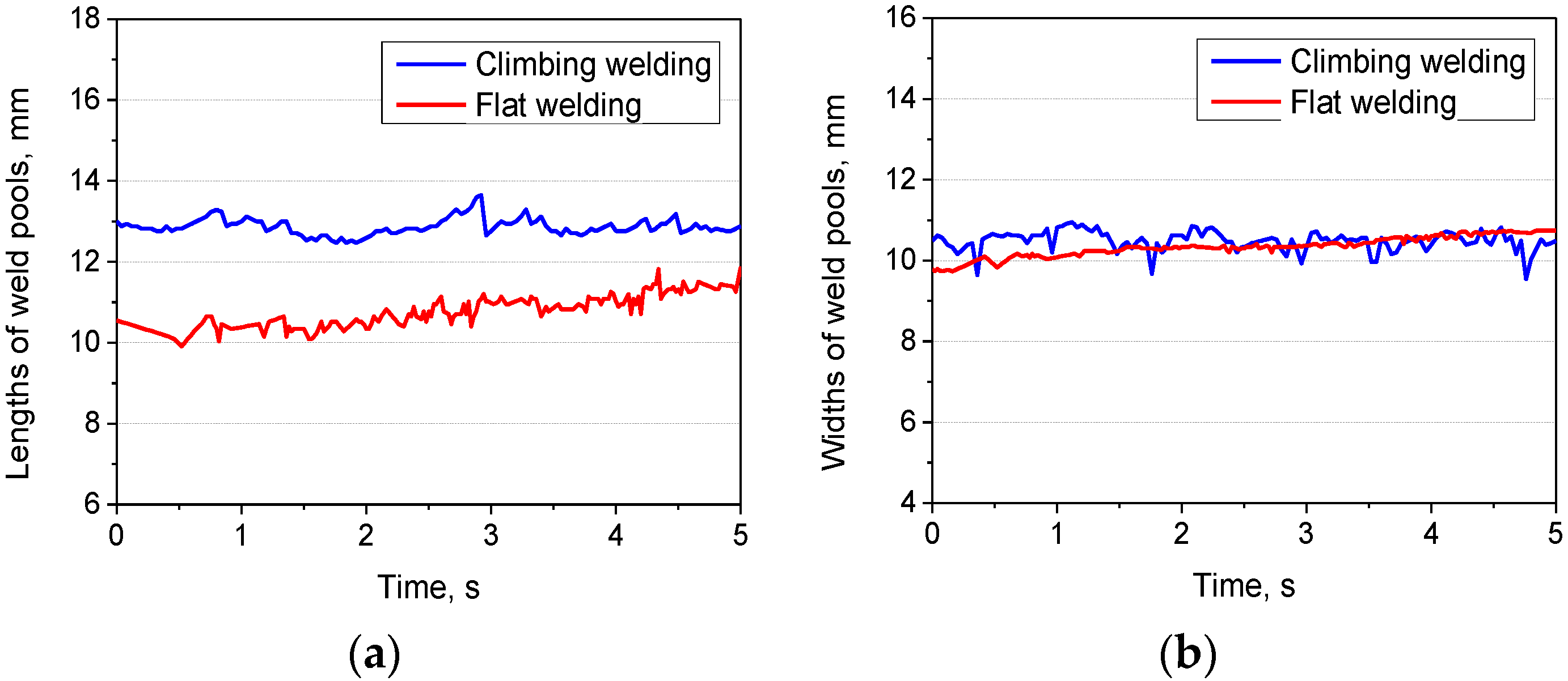
3.2.1. Dimensions of Weld Pools for Different Welding Positions

By using the high speed imaging system, videos were taken for the weld pools when welding with flat and climbing welding positions. Images from the videos were processed to obtain the features (mainly dimensions in this study) of weld pools, as shown in Figure 10. The main steps of imaging processing include:
(1)
Denoise through weighted average of gray levels of adjacent images.
(2)
Obtain weld pool profiles through image segmentation and derivation.
(3)
Calculate the lengths and widths of weld pools based the profiles and the calibration results of the high speed camera.
Using the aforementioned algorithms, the variations of the lengths and widths of weld pools during climbing welding and flat welding were obtained, as shown in Figure 11. The weld pool lengths for climbing welding (start end of a weld) are about 12.9 mm, which are longer than the flat weld pool (at the finish end of the weld) with lengths varying within a range of 10–11 mm and averaged at 10.7 mm. The widths of the weld pools for climbing and flat welding positions are 10.7 mm and 10.3 mm, respectively.
Table 5 lists the dimensions of weld pools obtained by CFD predictions and experimental measurements when welding 9.5 mm thick 2219 aluminum alloys with flat and climbing welding positions. Through comparison, it can be found the numerical predictions are in good agreement with the experimental observation, which validate the CFD numerical simulation model used in this paper. The model can take into account the influences of gravity action on the fluid flow of molten metal in weld pools, which enables it to analyze the effects of welding positions on the fluid flow behavior during welding reasonably.

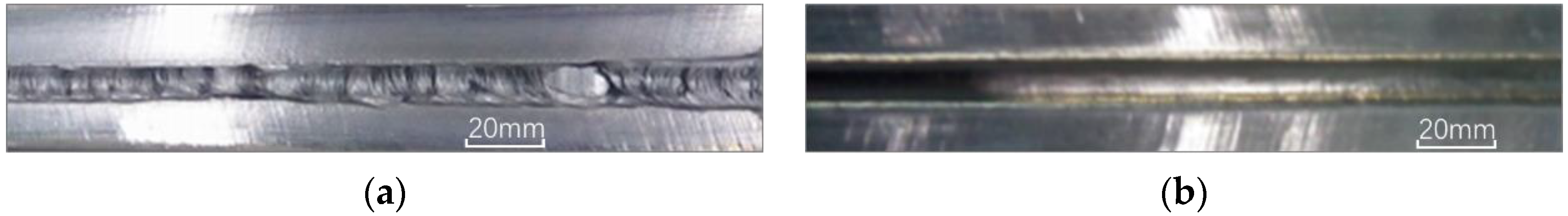
3.2.2. Weld Bead Appearances under Different Welding Positions

Figure 12 shows the morphologies of the welds produced under two welding positions. The weld bead produced at the start end of the shell joint (climbing position) has uneven surface and inconsistent width, i.e., a poor formation quality. In contrast, the weld bead at the finish end the shell joint (flat position) has smooth surface and consistent width that represent a good formation quality. Such a difference in the variations of weld widths are also reflected by the high speed imaging results shown in Figure 11b, where the abrupt changes in weld pool widths are obvious for climbing welding while the weld pool widths for flat welding change smoothly.

4. Discussion

In GTAW of the thick-sheet aluminum alloys structure shown in Figure 1, the welding position changes from the climbing position to the flat position. The fundamental difference between these two positions is the orientation of weld pool relative to gravity, as shown in Figure 13. In climbing welding, the gravity action on the weld pool has two components, one is perpendicular to the sheet surface (in sheet thickness direction) and the other is parallel to the sheet surface (lateral direction). In contrast, when flat welding, the gravity acts on the weld pool only in the sheet thickness direction, while the component parallel to the sheet surface is zero. Such a difference in the gravity action direction has a notable influence on the flow of molten metal in the weld pool and weld formation quality as revealed in this study, which is similar to those reported for the welding of steel and titanium alloys by laser and GMAW welding processes.
For flat welding, the metal flows dominantly downwards, and the velocity magnitudes are largest in the middle region of the weld pool. Such a flow pattern indicates a high penetrating capability, which is very critical in welding thick sheets. Excessive downward movement of molten metal at the bottom, however, may lead to weld sagging and should therefore be avoided, as found for not only the aluminum alloy in this study, but also steels and titanium alloys reported in other research [6,8]. For climbing welding, fluid flow is enhanced in lateral direction (afterwards), which results in a longer weld pool and makes the molten metal apt to flow out of the weld pool and form uneven weld surface. Meanwhile, the velocity is decreased in thickness direction, which leads to a weakened heat transfer between the top and the bottom portions of the weld pool and a decreased penetrating capability. This is manifested by the higher temperatures on the top portion and a smaller high-temperature region (with temperature higher than 909 K) at the bottom part of the climbing weld pool. Both the accelerated lateral metal outflow and the decreased penetrating capability could make the weld pool unstable, and finally lead to inconsistent weld bead when climbing welding.
To obtain good weld formation in climbing welding, it is therefore necessary to maintain enough penetrating capability and avoid excessive lateral flow of molten metal. One possible measure that may be taken is to employ an electrode with a sharper tip (smaller tip angle), which may generate a more concentrated arc and higher arc pressure, and then lead to improved weld pool stability and better weld formation. For welding with constantly changing welding positions, it may also be necessary to adjust manually or automatically the welding parameters (e.g., welding current and voltage) based on the on-line monitoring of the penetration state during welding process. Moreover, high-energy laser beams can be employed in combination with the tungsten arc to form a more penetrating and robust hybrid welding process in welding thick aluminum alloy sheets with changing welding positions.

5. Conclusions

Fluid flow characteristics and their relationship with the weld formation quality were studied for the GTAW of a 9.5 mm thick-sheet 2219 aluminum alloy shell structure, during which various welding positions are used. Based on the study, the following conclusions can be drawn:
(1) The orientations of weld pools relative to gravity are different for different welding positions. When climbing welding at the start end, gravity acts on the weld pool not only in sheet thickness direction but also in the direction parallel to the sheet surface. In contrast, when flat welding at the finish end, gravity only contributes to the fluid flow in sheet thickness direction.
(2) Compared to the flat welding position, the weld pool is shifted afterwards under gravity action, and a longer and wider top surface of the weld pool is generated for the climbing welding position than that of flat welding position. Meanwhile, lengths and widths of the bottom surfaces of the weld pools are close for the two welding positions.
(3) In comparison to that of flat welding, the fluid flow velocity in lateral (weld pool length) direction increases while the velocity in sheet thickness direction decrease when climbing welding. Such changes in velocities will result in decreased penetration capability and therefore unstable fluid flow in weld pool, and in turn poor weld formation quality (uneven weld surface and inconsistent weld width).

Author Contributions

B.C. completed the numerical modeling; D.D. and J.S. designed the experiments; H.X. and J.Z. performed the experiments; S.Y. analyzed the data; G.H. contributed the materials and analysis tools; and B.C. wrote the paper.

Funding

The research was financially supported by the National Natural Science Foundation of China (No. U1537205), and the Tsinghua University Initiative Scientific Research Program (No. 2014Z05093).

Conflicts of Interest

The authors declare no conflict of interest.

References

  1. Olabode, M.; Kah, P.; Martikainen, J. Aluminium alloys welding processes: Challenges, joint types, and process selection. Proc. Inst. Mech. Eng. 2013, 227, 1129–1137. [Google Scholar] [CrossRef]
  2. Junaida, M.; Baigb, M.N.; Shamirc, M.; Khand, F.N.; Rehmana, K.; Haiderea, J. A comparative study of pulsed laser and pulsed TIG welding of Ti-5Al-2.5Sn titanium alloy sheet. J. Mater. Process. Technol. 2017, 242, 24–38. [Google Scholar] [CrossRef]
  3. Zhang, Q.L.; Yang, C.L.; Lin, S.B.; Fan, C.L. Horizontal welding of aluminium alloys by soft plasma arc. Proc. Inst. Mech. Eng. 2014, 228, 1481–1490. [Google Scholar] [CrossRef]
  4. Kou, S. Fluid flow and solidification in welding: Three decades of fundamental research at the University of Wisconsin. Weld. J. 2012, 91, 287s–302s. [Google Scholar]
  5. Sohail, M.; Han, S.W.; Na, S.J.; Gumenyuk, A.; Rethmeier, M. Numerical investigation of energy input characteristics for high-power fiber laser welding at different positions. Int. J. Adv. Manuf. Technol. 2015, 80, 931–946. [Google Scholar] [CrossRef]
  6. Guo, W.; Liu, Q.; Francis, J.A.; Crowther, D.; Thompson, A.; Liu, Z.; Lin, L. Comparison of laser welds in thick section S700 high-strength steel manufactured in flat (1G) and horizontal (2G) positions. CIRP Ann. 2015, 64, 197–200. [Google Scholar] [CrossRef]
  7. Shen, X.F.; Li, L.; Guo, W.; Teng, W.H.; He, W.P. Comparison of processing window and porosity distribution in laser welding of 10 mm thick 30CrMnSiA ultrahigh strength between flat (1G) and horizontal (2G) positions. J. Laser Appl. 2016, 28. [Google Scholar] [CrossRef]
  8. Chang, B.H.; Yuan, Z.; Pu, H.T.; Li, H.G.; Cheng, H.; Du, D.; Shan, J.G. A comparative study on the laser welding of Ti6Al4V alloy sheets in flat and horizontal positions. Appl. Sci. 2017, 7. [Google Scholar] [CrossRef]
  9. Chang, B.H.; Yuan, Z.; Pu, H.T.; Li, H.G.; Cheng, H.; Du, D.; Shan, J.G. Study of gravity effects on titanium laser welding in the vertical position. Materials 2017, 10. [Google Scholar] [CrossRef] [PubMed]
  10. Kumar, A.; Debroy, T. Heat transfer and fluid flow during gas–metal-arc fillet welding for various joint configurations and welding positions. Metall. Mater. Trans. A 2007, 38, 506–519. [Google Scholar] [CrossRef]
  11. Cho, D.W.; Na, S.J.; Cho, M.H.; Lee, J.S. A study on V-groove GMAW for various welding positions. J. Mater. Process. Technol. 2013, 213, 1640–1652. [Google Scholar] [CrossRef]
  12. Cai, X.Y.; Fan, C.L.; Lin, S.B.; Yang, C.L.; Bai, J.Y. Molten pool behaviors and weld forming characteristics of all-position tandem narrow gap GMAW. Int. J. Adv. Manuf. Technol. 2016, 87, 2437–2444. [Google Scholar] [CrossRef]
  13. Xu, W.H.; Lin, S.B.; Fan, C.L.; Yang, C.L. Prediction and optimization of weld bead geometry in oscillating arc narrow gap all-position GMA welding. Int. J. Adv. Manuf. Technol. 2015, 79, 183–196. [Google Scholar] [CrossRef]
  14. Zacharia, T.; Eraslan, A.H.; Aidun, D.K. Modeling of autogenous welding. Weld. J. 1988, 67, 53s–62s. [Google Scholar]
  15. Kang, N.Y.; Singh, J.; Kulkarni, A.K. Gravitational effects on the weld pool shape and microstructural evolution during gas tungsten arc and laser beam welding of 304 stainless steel and Al-4wt% Cu alloy. Ann. N. Y. Acad. Sci. 2004, 1027, 529–549. [Google Scholar] [CrossRef] [PubMed]
  16. Kang, N.; Mahank, T.A.; Kulkarni, A.K.; Singh, J. Effects of gravitational orientation on surface deformation and weld pool geometry during gas tungsten arc welding. Mater. Manuf. Process. 2003, 18, 169–180. [Google Scholar] [CrossRef]
  17. Lin, Q. A Study on the Heat Source Models in Deep Penetration Laser Welding. Bachelor’s Thesis, Tsinghua University, Beijing, China, 2014. [Google Scholar]
  18. Li, T.Q.; Wu, C.S. An analytic formula describing the plasma arc pressure distribution. China Weld. 2014, 23, 7–11. [Google Scholar]
  19. Li, T.Q.; Wu, C.S. Numerical simulation of plasma arc welding with keyhole-dependent heat source and arc pressure distribution. Int. J. Adv. Manuf. Technol. 2015, 78, 593–602. [Google Scholar] [CrossRef]
  20. Mills, K.C. Recommended Values of Thermophysical Properties for Selected Commercial Alloys; Wookhead Publishing Limited: Cambridge, UK, 2002; ISBN 1855735695. [Google Scholar]
Figure 1. Shape and dimensions of the spherical shell ring structure: (a) shape of the structure; and (b) dimensions of the structure (unit: mm).
Applsci 08 01215 g001
Figure 2. Two typical welding positions studied.
Applsci 08 01215 g002
Figure 3. Dimensions of computation domain and the mesh used in CFD (unit: mm): (a) dimensions of the computation domain; and (b) mesh divisions in CFD.
Applsci 08 01215 g003
Figure 4. Equipment setup and high speed imaging system for GTAW.
Applsci 08 01215 g004
Figure 5. Shape and dimensions of the weld pool for flat welding (at finish point): (a) whole model; and (b) magnified melt pool region.
Applsci 08 01215 g005
Figure 6. Shape and dimensions of the weld pool for climbing welding (at start point): (a) whole model; and (b) magnified melt pool region.
Applsci 08 01215 g006
Figure 7. Comparison of the weld pools for flat and climbing welding positions.
Applsci 08 01215 g007
Figure 8. Velocity fields in the weld pool for flat welding (unit: m/s): (a) whole model; and (b) magnified melt pool region.
Applsci 08 01215 g008aApplsci 08 01215 g008b
Figure 9. Velocity fields in the weld pool for climbing welding (unit: m/s): (a) whole model; and (b) magnified melt pool region.
Applsci 08 01215 g009aApplsci 08 01215 g009b
Figure 10. Processing of images to obtain dimensions of weld pools: (a) an image captured; and (b) feature extraction of weld pools.
Applsci 08 01215 g010
Figure 11. Variations of lengths and widths of the weld pools during climbing welding and flat welding: (a) lengths; and (b) widths.
Applsci 08 01215 g011
Figure 12. Weld formation for two welding positions: (a) climbing welding; and (b) flat welding.
Applsci 08 01215 g012
Figure 13. Orientations of weld pools relative to gravity for the two welding positions: (a) climbing welding (start end); and (b) flat welding (finish end).
Applsci 08 01215 g013
Table 1. Chemical composition of the aluminum alloy 2219 sheets (wt%).
ElementsCuMnFeZrVSiTiZnMgAl
Content, wt%6.090.290.160.160.100.070.050.0060.004Bal.
Table 2. Process and material properties parameters used in CFD numerical modeling.
Parameters, unitsValues
Sheet thickness, h, mm9.5
Welding current, I, A270
Welding voltage, U, V24.5
Welding speed, v, mm/min200
Radius of heat source, r0, mm5.0
Radius of pressure source, rp, mm5.0
Thermal efficiency, η0.60
Specific heat, Cp, J/(kg⋅K)850
Melting enthalpy, ΔHm, J/kg2.97 × 105
Thermal conductivity, λ, W/(m⋅K)187
Viscosity, μ, kg/(m⋅s)1.2 × 10−3
Forced convection heat transfer coefficient, hf, W/(m2⋅K)500
Natural convection heat transfer coefficient, hn, W/(m2⋅K)20
Space permeability ,   μ 0 , N/A24π × 10−7
Surface tension, σ, N/m0.914 − 0.35 × 10⁻³ × (T − 930)
Thermal gradient of surface tension, G, N/(m⋅K)−0.35 × 10−3
Table 3. Process parameters used in GTAW and high speed imaging experiments.
ParametersValues
Sheet thickness, h/mm9.5
Welding current, I/A270
Welding voltage, U/V24.5
Welding speed, v/(mm/min)200
Image size, D/pixel512 × 512
Exposure time, te/ms1
Frame rate, f/fps250
Table 4. Dimensions of weld pools numerically predicted for flat and climbing welding positions.
Positions of MeasurementClimbing Welding (Start end)Flat Welding (Finish end)
Length, mmWidth, mmLength, mmWidth, mm
Top surface12.310.110.69.3
Bottom surface9.98.59.58.4
Table 5. Dimensions of weld pools obtained by CFD predictions and experimental measurements.
MethodsClimbing Welding (Start end)Flat Welding (Finish end)
Lengths, mm Widths, mm Lengths, mm Widths, mm
Experiments12.910.510.710.3
CFD simulation12.310.110.69.3
Error, %4.73.80.99.7

