Review

Coherent Optical Field Manipulation and Optical Information Processing Based on Electromagnetically-Induced Transparency Effect in Pr3+:Y2SiO5 Crystal

1
The MOE Key Laboratory of Weak-Light Nonlinear Photonics, School of Physics and TEDA Applied Physics Institute, Nankai University, Tianjin 300457, China
2
College of Electronic and electrical engineering, Henan Normal University, Xinxiang 453007, China
3
Collaborative Innovation Center of Extreme Optics, Shanxi University, Taiyuan 030006, China
*
Author to whom correspondence should be addressed.
Appl. Sci. 2018, 8(7), 1179; https://doi.org/10.3390/app8071179
Submission received: 25 June 2018 / Revised: 14 July 2018 / Accepted: 16 July 2018 / Published: 19 July 2018
(This article belongs to the Special Issue Nonlinear Optical Materials and Phenomena)

Abstract

:
We reviewed the recent progress in coherent manipulation on light fields based on the electromagnetically-induced transparency (EIT) effect in Pr 3 + -doped Y 2 SiO 5 crystal. The results show that, on one hand, the atomic coherence grating, formed when the light pulse is stored in Pr 3 + : Y 2 SiO 5 crystal under the EIT condition has similar properties to the traditional holographic grating. On the other hand, the atomic coherence grating has its own unique characteristics that are different from those of traditional holographic grating. The EIT-induced nonlinearity and atomic coherence gratings can be used to manipulate the amplitude, the phase and the polarization state of light fields; therefore, they are of important applications for optical signal processing, quantum information processing and imaging processing.

1. Introduction

Coherent manipulation of the optical fields and material properties via the quantum interference effect is an important issue in both fundamental physics and applied physics. The electromagnetically-induced transparency (EIT) effect [1,2,3] is the result of destructive quantum interference among different atomic transitions and is an effective way of modifying the material properties and manipulating the light fields. The absorption of EIT media, even when the light field is resonantly applied on the atomic transition, will be significantly reduced or even eliminated under the two-photon resonant condition. Yet, the EIT effect is different from the Autler–Townes splitting which originates from energy level splitting due to strong field-driven interactions [4,5,6,7]. The EIT effect is accompanied by a strong spectral dispersion of materials, which leads to slow light [8]. There are various ways to generate slow light, for instance, through the EIT effect [8,9,10,11], the atomic frequency comb [12,13,14], the photorefractive wave-mixing [15,16], coherent population oscillations [17,18], stimulated Raman scattering [19] and stimulated Brillouin scattering [20], and so on. Nevertheless, the EIT effect is also capable of storing light pluses or quantum states of photons by simply halting the light pulses; therefore, it has various potential applications in both classical optics and quantum optics [9,10]. Liu et al. [21] demonstrated the storage and retrieval of light pulses in a cold cloud of sodium atoms, and Turukhin et al. [22] reported the light pulse storage in Pr 3 + -doped Y 2 SiO 5 (Pr:YSO) crystal. The storage and retrieval of transverse multimode images was achieved in hot atomic rubidium vapor by Vudyasetu et al. [23], and the multiplexing storage of light pules was also demonstrated in Pr:YSO crystal by Tu et al. [24]. In addition, storage of the quantum state of light, such as a single photon and entangled photon pairs, was demonstrated [25,26,27,28]. More recently, highly efficient coherent optical memory with a storage efficiency of 92% and a time-bandwidth product of 1200 was reported by Hsiao et al. in Cs atomic vapor [29]. In addition, the influences from the environment of the atomic ensemble, such as the buffer gas in the atomic vapor, the substrates in EIT solids and the cavity confinement, on the EIT effect and EIT-based photon propagation and storage were studied intensively [30,31]. EIT analogies in artificial systems other than the atomic ensemble, such as superconducting quantum circuits and whispering-gallery microcavities, were explored in detail, which was motivated by potential applications in quantum information processing [5,32,33,34].
The EIT effect can also be used to manipulate the light fields and to generate new optical fields with novel spatial structures or properties. Kuzmich et al. [35] generated nonclassical photon pairs through collective emission from a cloud of cold Cs atoms. Eisaman et al. [25] generated a single photon with tunable frequency, timing and bandwidth in Rb atomic vapors based on the EIT effect. The intensity dependence of the EIT effect was used to suppress the light diffraction to achieve a super-resolved image [36,37,38], optical diffraction in the momentum space and atomic diffusion caused by the thermal atomic motion of atomic vapors [39,40]. In addition, special phase structures, such as optical vortexes, could be stored and manipulated in EIT media [41,42,43], even at the single photon level [28], which has great practical application in optical communications and quantum information processing.
It was realized, even in the early stages, that the EIT effect can enhance nonlinear optical effects. Harris et al. [1] showed theoretically that third-order susceptibility can be resonantly enhanced in EIT media, which was soon experimentally verified in both atomic vapors and solids, such as Pr:YSO crystal [44,45,46,47,48]. A rapidly varying refractive index in the spectral domain, therefore having a high spectral dispersion of EIT media, was predicted theoretically and confirmed experimentally, and could be used to control the group velocity of light [49,50]. In cases with slow light, the interaction between the light field and the EIT media was significantly enhanced, and giant Kerr nonlinearity was observed in the EIT media [21]. Due to the intensity dependence of the EIT effect, a spatially varying refractive index change could be induced and an EIT-induced spatial soliton was predicted theoretically and observed experimentally [51,52]. For more detail about the enhanced optical nonlinearity in the EIT media, one can refer to review articles, for instance, by Marangos [10], Fleischhauer et al. [9] and Min et al. [53].
Most of the early studies on the EIT effect were performed in atomic vapors due to their advantage of having a long atom decoherence time [2,23,39,40,42,54,55]. Compared to atomic vapors, solid state materials are robust, easy to fabricate and post-process, of high atomic density and have no atomic diffusion, although they need cryogenic temperature to suppress the dephasing effect caused by phonons. Fortunately, the decoherence time of rare earth ions is long enough for many applications, especially, the storage time of light pulses as long as minutes or even hours was achieved in Pr:YSO or Eu:YSO crystals [56,57]. In this paper, we review the recent progress on the manipulation of light fields and its application in optical signal processing based on the EIT effect in Pr:YSO crystal.

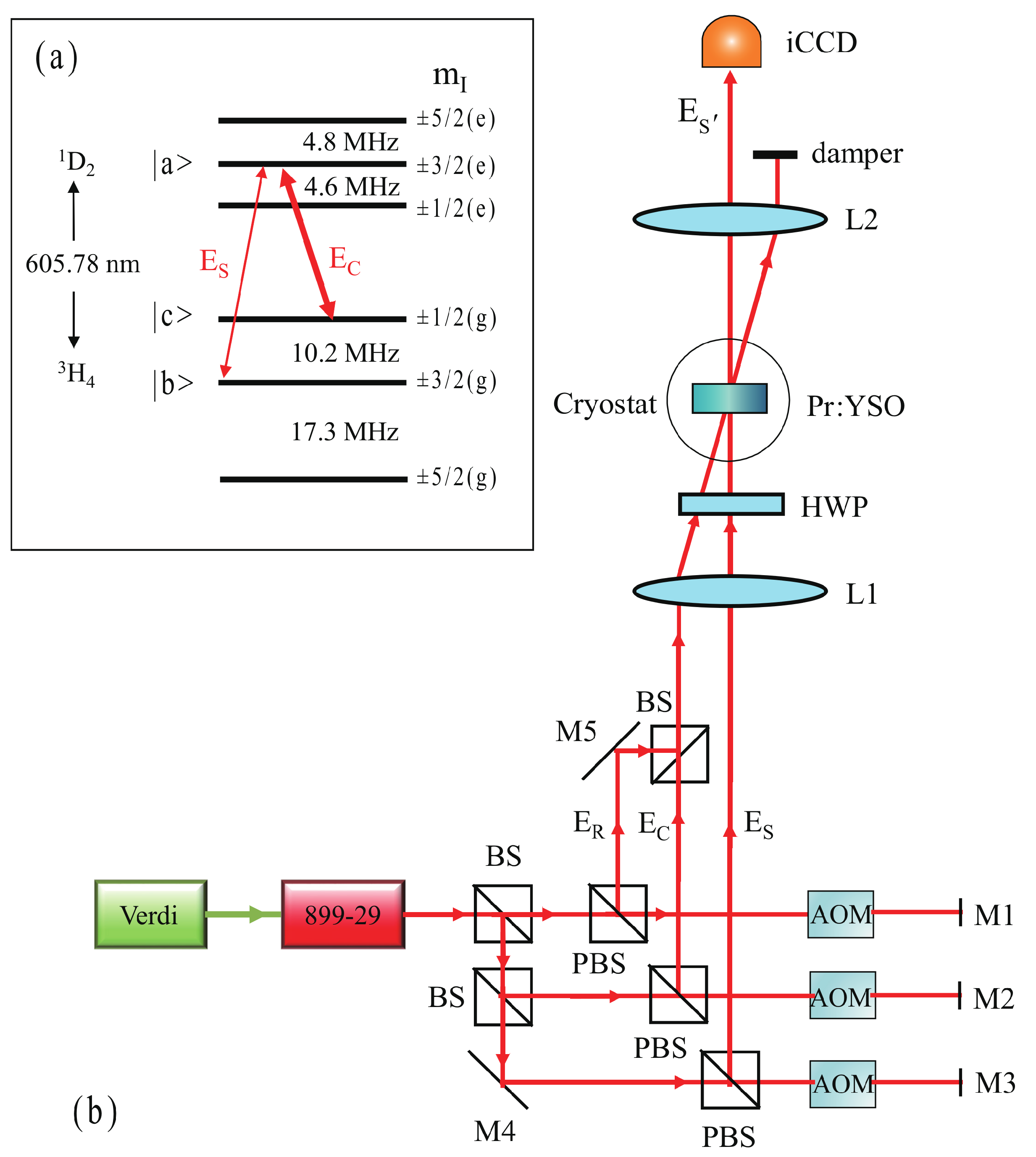
2. Materials and Experimental Setup

Rare earth elements refer to 17 specific elements in the periodic table, including fifteen lanthanides with atomic numbers from 57 to 71, scandium and yttrium. Most rare earth elements can be in the trivalent state (i.e., Ce, Pr, Nd, Eu, Gd, Tb, Dy, Ho, Er, Tm and Yb) or the divalent state (i.e., Sm, Dy and Tm), shelled by fully filled 5s, 5p or 6s when doped into crystals. The fully filled shell isolates the 4f–4f transitions from the environmental disturbances; therefore, the rare earth ions have a long decoherence time and energy-level lifetime, usually in the order of microseconds or milliseconds, indicating that rare earth ions are ideal candidates for quantum memories. To further minimize the influence from the nuclear magnetic moment of crystalline lattice ions, host crystals with small nuclear magnetic moments should be selected, for example, Y 2 SiO 5 , LaF 3 , LaCl 2 , YAlO 3 and LiYF 4 crystals [56,58]. Praseodymium and europium are the two most-used rare earth ions in coherent quantum processing.
We used Pr:YSO crystal as the material platform in the following EIT-related experiments. YSO is a monoclinic crystal and belongs to the C 2 h 6 space group. The Pr 3 + ions have two inequivalent crystallographic sites to substitute Y 3 + ions, which can be marked as site 1 and site 2. In the EIT-related experiments, one usually uses the hyperfine energy levels of transition 3 H 4 1 D 2 of Pr 3 + ions. Equall et al. [58] analyzed the hyperfine multiplets of the ground-state 3 H 4 and the excited-state 1 D 2 of Pr 3 + ions on these two different sites at 1.4 K, and those on site 1 are shown in Figure 1a. The population and dephasing lifetimes of the excited state, 1 D 2 , of Pr 3 + ions on site 1 are T 1 = 164   μ s and T 2 = 152   μ s, respectively, while those on site 2 are T 1 = 222   μ s and T 2 = 377   μ s, respectively. The population lifetime of the hyperfine multiplets of the ground-state, 3 H 4 , is in the order of 100 s [59,60], which sets an up-limit of the storage lifetime of light pulses in Pr:YSO crystal. Here, we used 3-mm Pr:YSO crystal with a doping concentration of 0.05% ( Pr 3 + ions on site 1) in the following experiments, and the central wavelength of the transition 3 H 4 1 D 2 was 605.78 nm.
Figure 1b shows the schematic experimental setup for the EIT-related experiments. A laser beam (from a tunable dye laser 899-29, Coherent Inc., Santa Clara, USA) operating at 605.78 nm with a bandwidth of 0.5 MHz was split into three beams, serving as the probe or signal, E S , the coupling, E C , and the readout, E R , beams, respectively, and their intensity and frequency could be modulated by respective acousto-optic modulators (AOMs) independently. The AOMs worked in the double-pass configuration to eliminate the movement of light spots. The three beams were then focused into a 3-mm Pr:YSO crystal propagating along the b-axis of the crystal (also along the 3-mm side). The crystal was kept at 3.4 K in a cryostat (Optistat AC-V, Oxford Instruments) to reduce the decoherence effect caused by phonons. The output signals after the cryostat were recorded by an intensified charge-coupled device (iCCD). The EIT effect can be observed and light pulses can be stored in Pr:YSO crystals under appropriate conditions (the details can be found in the following sections).

3. EIT Effect and Light Pulse Storage via Atomic Coherence Gratings

To demonstrate the EIT effect in Pr:YSO crystal, one should first prepare a spectrally-isolated Λ -type three-level ensemble, as shown in Figure 2a, in which all ions in the isolated ensemble are populated on the ground-state energy level | b . This can be achieved by combining the optical pumping and spectral hole-burning techniques [24,61]. Then, by lauching a strong coupling beam, E C , and a weak probe beam, E S , into the crystal simultaneously, the absorption of the probe beam can be significantly reduced or even eliminated due to the destructive quantum interference between the two atomic transitions, | a | b and | a | c , under the two-photon resonant condition, as shown in Figure 2d. According to the Kramers–Kronig relationship, the EIT effect is accompanied with a dramatic normal dispersion near the resonant frequency of the probe beam, which significantly reduces the group velocity v g of the probe pulse
v g = d ω S d k S | δ S = 0 = c n + ω S ( d n d ω S ) ,
where c is the speed of light in a vacuum; n is the refractive index of the Pr:YSO crystal at the operating wavelength, λ = 605.78 nm; ω S and k S are the angular frequency and the wavenumber of the probe light, respectively; and δ S = ω S ω a c is the frequency detuning of the probe light with respect to the resonant frequency, ω a c , of the atomic transition, | a | c , respectively. A time delay of ∼0.7 μ s was observed with a 5- μ s, 0.5-mW Gaussian probe pulse and a 5-mW coupling beam driving resonantly the Λ -type three-level ensemble, corresponding to a group velocity of 4.3 × 10 3 m/s in the 3-mm Pr:YSO crystal.
The group velocity of light pulses in Pr:YSO crystal in the EIT condition is dependent on the coupling light intensity. One can halt and therefore store the light pulses in the EIT media by adiabatically switching off the coupling beam. This process can be explained theoretically by the concept of dark-state polaritons [62], and the signal light pulse can be mapped onto the dark-state in the form of atomic coherence grating, which is a coherent superposition of the two ground-state levels, | b and | c . The amplitude of the stored spin coherence is proportional to the density matrix element ρ c b 0 [63].
ρ c b 0 Ω S Ω C e i k g · r i ω c b t ,
where Ω S = μ a b E S / and Ω C = μ a c E C / are the Rabi frequencies of the signal and the coupling light pulses, respectively, and μ a b and μ a c are the dipole moments of the corresponding atomic transitions. The superscript ’☆’ denotes the complex conjugate, k g = k S k C is the wave vector of the atomic coherence gratings, k S and k C are the wave vectors of the signal and the coupling light pulses; r is the spatial coordinate; ω c b is the resonant frequency of transition | c | b ; and t is the time coordinate.
Due to various decoherence effects such as the dephasing effect and the interaction with phonons, the stored light pulses decay exponentially with a lifetime of τ , which was measured to be ∼30 μ s in Pr:YSO crystal at 3.4 K. The storage lifetime, τ , can be prolonged by using various techniques to decouple the hyperfine multiplets of the ground-state 3 H 4 from the environmental dephasing effects, and storage lifetimes in the order of minutes and hours were reported for Pr:YSO and Eu:YSO crystals [56,57], respectively. Within the storage lifetime, τ , the halted light pulses can be re-accelerated and retrieved by launching a readout beam, E R , along the propagation direction of the coupling beam, as shown in Figure 2b. The time sequence of the light pulses, including the signal, E S , the coupling, E C , the readout, E R , and the retrieved pulse, E S , are shown in Figure 2c.
Similar to the conventional holographic gratings, the retrieval of the stored light pulses is of high angular and spectral selectivity [24,63], as shown in Figure 3, where the full width at half maximum (FWHM) of the angular rocking curve and the spectral detuning rocking curve were measured to be 1 ° and 2 MHz, respectively, in the 3-mm Pr:YSO crystal at 3.4 K. Angular and spectral selectivity are the requirements of the phase matching condition during the light pulse storage and retrieval process.
Δ k = k S k C + k R k S ,
where k R and k S correspond to the wave vectors of the readout and the retrieved light pulses, respectively. The retrieved light pulse, E S , can be viewed as a result of constructive interference of the emission | a | c of all atoms in the k S direction and is written as
E S L sinc ( | Δ k | L / 2 ) ,
where L is the field–atom interaction length. Note that the FWHM of the spectral detuning curve is much narrower than that of the volume holographic grating; this is the result of interplay between the narrow EIT spectral window and the linewidth of the laser beam. All of them are of a spectral bandwidth in the order of MHz.
The angular selectivity of atomic coherence gratings is the basis for the angular multiplexing technique, which has many potential applications such as increasing the storage capacity of light pulses and allowing angularly addressable delay lines and buffer memory. Tu et al. [24] demonstrated the angular multiplexing storage of light pulses and addressable multi-channel optical buffer memory in Pr:YSO crystal based on the EIT effect, as shown in Figure 4. No cross-talk among channels was observed as long as the angular distance between neighboring channels was larger than the FWHM of the angular rocking curve of atomic coherence gratings.

4. Coherent Manipulation on Light Fields via Atomic Coherence Gratings

We note that, similar to the traditional volume holographic gratings, the EIT-based atomic coherence gratings, which are proportional to the product of the signal and the coupling fields, as shown by Equation (2), also record both the amplitude and the phase of the signal light field. More interestingly, when the atomic coherence gratings were re-accelerated by a phase-matched readout beam, the retrieved output signal field was proportional to the product of the signal, the coupling and the readout fields, which provides an active and effective way to manipulate the interacting light fields through the light pulse storage and retrieval technique based on the EIT effect. In the following text, we show several examples of manipulation on the phase and the amplitude of the light fields and its applications in signal processing and imaging processing.

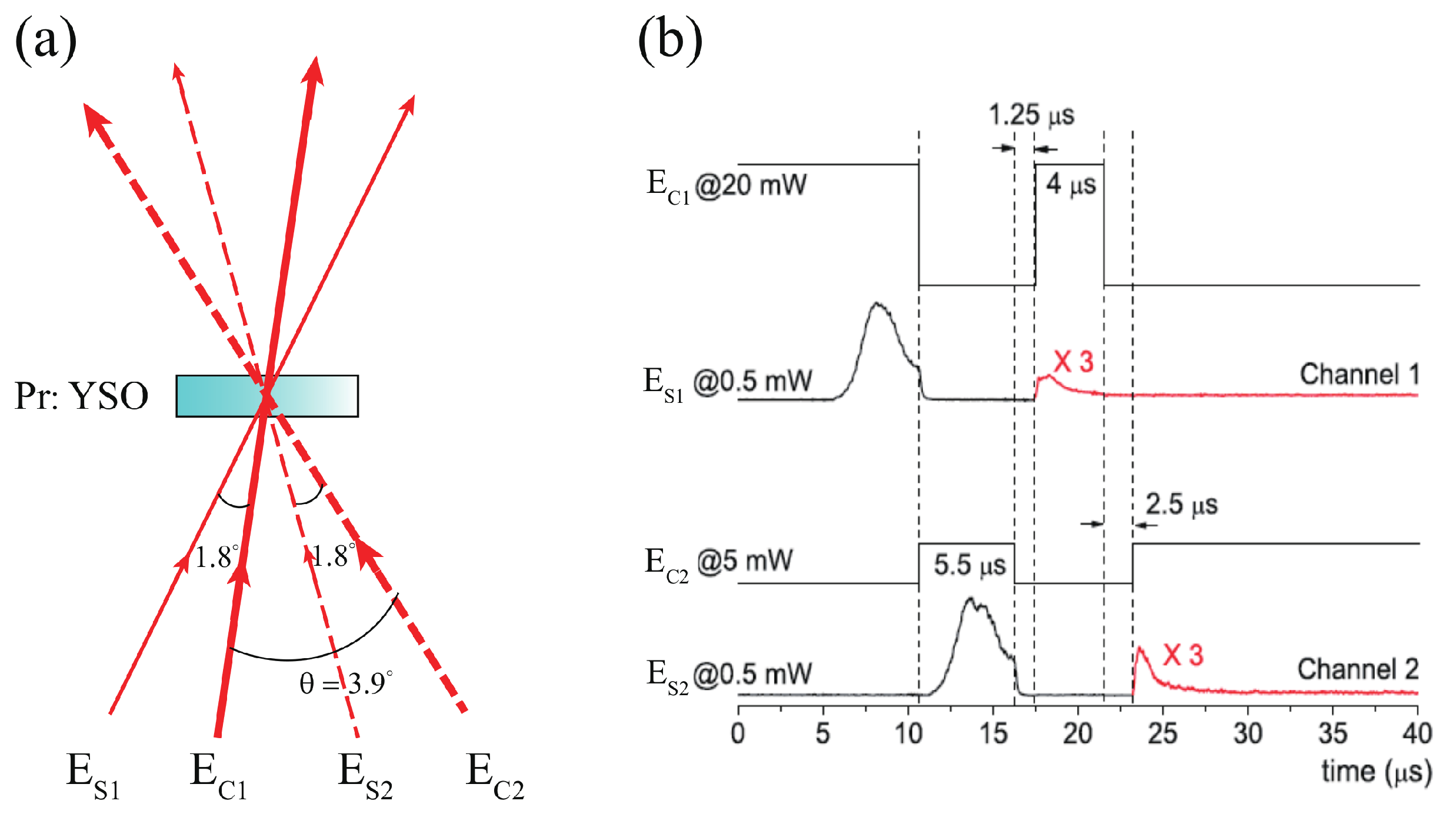
4.1. Nondegenerate Phase-Conjugate Wave

The phase aberration induced by spatial inhomogeneities during the propagation of light is a severe problem in coherent imaging systems [64,65], which causes the image to be blurred or distorted, therefore losing accurate information. Apart from all other correction algorithms, one of the phase aberration correction methods, which is simple in principle, is to use the phase-conjugate wave [66]. The phase aberration can be removed by letting the aberrated phase-conjugate wave pass in the reverse direction through the same phase aberration medium; therefore, the phase-conjugate wave is also called the time-reversal wave. An optical phase-conjugate wave can be generated through various nonlinear optical processes, for instance, three-wave mixing [67,68], four-wave mixing [69,70,71,72], photorefractive wave-mixing [73], backward stimulated scatterring and emission [74,75,76,77] and photon-echo process in a resonant medium [78,79]. In general, the key to generate phase-conjugate waves is to form a holographic grating, through which the reversal wave front with identical transverse distribution is restored.
We note that atomic coherence grating is induced during the light pulse storage based on the EIT effect; therefore, it is possible, in principle, to generate phase-conjugate waves based on the EIT-induced atomic coherence grating. Ham et al. [80] reported the generation of phase-conjugate waves in Pr:YSO crystal based on the EIT effect in a four-wave mixing configuration, in which the EIT effect was proved to significantly enhance the conversion efficiency of the phase-conjugate wave. In addition, in a coherently prepared atomic vapor, Zibrov et al. [81] proposed and realized the transportation and time reversal of light pulses between different spatial and temporal points via atomic coherence.
We demonstrated a nondegenerate phase-conjugate wave in Pr:YSO crystal through the EIT-based light pulse storage and retrieval technique. Figure 5a shows the experimental configuration used to generate the phase-conjugate wave. Here, we first stored a phase-distorted signal pulse, E S , in Pr:YSO crystal based on the EIT effect by adiabatically switching off the coupling beam, E C . Then, we launched a readout beam, E R , propagating in the opposite direction with respect to the coupling beam to re-accelerate the atomic coherence grating, and a new field, E S , which was the phase-conjugate wave of the stored signal pulse with distorted phase distribution, was generated. Note that, in the presence of the readout beam, the atomic coherence grating re-accelerates and moves together with the new field, E S , and under the constraint of the phase-matching condition, the frequency of the readout beam, E R , is required to be different from that of the coupling beam, E C , but the same as that of the signal pulse, E S , while the frequency of the E S field is the same as that of E C but different from that of the signal pulse, E S ; that is, the E S field is a nondegenerate phase-conjugate wave of the signal pulse. The frequency relationship between the interacting light fields was verified by using the frequency beating technique [63]. Figure 5b depicts the recovered beam spot after the E S field repassed through the phase-distorted glass slit reversely, showing the capability of the nondegenerate phase-conjugate wave to remove the phase distortion of the signal pulse. For comparison, Figure 5c shows the speckled beam spot when the readout beam is slightly deviated from the phase-matching condition with an angular detuning of 1.7 mrad. It can be seen that, in this case, the beam spot is messy speckled.

4.2. Manipulation on Optical Vortexes

An optical vortex carrying an optical topological charge (OTC), m, with m being an integer, is of an azimuthal phase structure in the form e i m ϕ , which forms a phase singularity [82,83,84]. Allen et al. [85] pointed out that each photon in such an optical vortex beam with an OTC m carries an orbital angular momentum of m . The transfer of the orbital angular momentum of photons to the micro/nanoparticles during the light–matter interaction can be used to trap and manipulate the micro/nanoparticles. The eigenmodes of the orbital angualr momentum, i.e., the Laguerre–Gaussian modes, are mutually orthogonal and can be used for mode-multiplexing to increase the signal transmission capacity in fiber optical communications, and these eigenmodes also span an infinite dimensional discrete Hilbert space for quantum information processing and quantum computation. Optical vortex beams have many potential applications, such as optical signal processing, optical trapping, optical communications and quantum information processing, and the generation of and manipulation on an optical vortex beam has become one of the hot topics recently [86]. Several methods have been developed to generate and manipulate the optical vortex beam, for example, through linear optical elements, such as q plates, Dove prisms, mode converters by cylindrical lens, and computer-generated holograms with a forklike dislocation, or through nonlinear optical processes, such as four-wave mixing and spontaneous parametric down-conversion [82,83,84,86].
Similar to the conventional holographic gratings, the EIT-based atomic coherence gratings can also record both the amplitude and the phase information of a light field, therefore, it is possible to record and recover special phase structures carried by the light field. Pugatch et al. [41] reported the storage of an optical vortex based on the EIT effect in a vapor of Rb atoms, which proved to be topologically stable to atomic diffusion. More recently, the storage and retrieval of optical vortexes in the single-photon level was also demonstrated in atomic vapor [27,28,87].
We demonstrated the transfer of OTC and mode conversion of optical vortexes through EIT-based light pulse buffer memory in Pr:YSO crystal [43]. The experimental setup was similar to that in Figure 1 except that the two lenses, L 1 and L 2 , were of the same focal length f, and the Pr:YSO crystal was placed on the confocal plane of two lenses. The signal, E S , the coupling, E C , and the readout, E R , were able to carry OTC and were focused into the Pr:YSO crystal by lens L 1 , and then the retrieved output signal pulses, E S , were mapped onto the iCCD to record the intensity profile. An additional plane wave was introduced to interfer with the retrieved output signal pulses to show the phase structure of the retrieved output signal pulses. The optical vortex carried by the signal pulse, E S , could be stored in Pr:YSO crystal based on the EIT effect and then retrieved with the help of a Gaussian coupling beam, E C , and a Gaussian readout beam, E R . Although the EIT-based storage and retrieval of the optical vortexes are temporally separated, the phase-matching condition should be satisfied, and the retrieved output signal pulses, E S , can be expressed as [43]
| E S | e i ϕ S | E S E C * E R | e i ( ϕ S ϕ C + ϕ R ) e i Δ k · r d r 3 ,
where ϕ j ( j = S , C , R , S ) is the transverse profile of the phase of the corresponding beam. Supposing that the OTC carried by each interacting beam is m j ( j = S , C , R , S ) , under the phase-matching conditions and according to Equation (5), the conservation law of OTCs is carried by the interacting beams:
m S = m S m C + m R .
This indicates that the OTCs carried by the signal, E S , the coupling, E C and the readout, E R can be transfered to the retrieved output signal field, E S . Note that the sign of OTC will be flipped when it is transfered from the coupling beam, E C , as shown in Figure 6. More interestingly, by transfering OTCs from several beams simultaneously to the retrieved output signal pulse, E S , one can achieve mode conversion of the optical vortex based on this two-step light pulse storage and retrieval process and therefore construct high-order optical vortexes from low-order optical vortexes. Figure 7 shows a case where m S = 1 , m C = 0 and m R = 1 , respectively. It can be seen that the OTC of the retrieved output signal field, E S , is m S = 2 , in accordance with Equation (6). This mode conversion operation may have potential applications in optical communications and quantum information processing.

4.3. First-Order Subwavelength Interference

Subwavelength interference is capable of breaking through the classical Rayleigh spatial resolution limitation of a light field [88]; therefore, it has many potential applications, such as super-resolved optical lithography and precision measurement [89,90,91,92]. There are various ways to achieve subwavelength interference, for example, by using the higher-order optical coherence of an entangled quantum NOON state [93,94,95] or phase-correlated classical light sources [96,97,98,99,100,101]. For the quantum light sources, interfering fringes with a visibility up to 100% can be reached theoretically, whereas for practical applications, such as quantum lithography, the main challenge is the conflicting requirements on the light field strength—it should be strong enough for efficient multi-photon nonlinearity but weak enough to maintain the quantum features [92]. For classical light sources, the fringe visibility of subwavelength interference is usually relatively low in comparison with that of quantum light sources. In general, efficient n-photon nonlinear optical processes and recording materials are required to achieve a subwavelength spatial resolution with an effective wavelength of λ / n , which is extremely challenging in practice. Therefore, in view of practical applications, high visibility first-order subwavelength interference that corresponds to the one-photon absorption process and is linear in light intensity is extremely in demand [102].
We demonstrated that first-order subwavelength interference with high visibility through a spatial frequency doubling process can be achieved using the light pulse storage and retrieval technique based on the EIT effect in Pr:YSO crystal [103]. As shown in Figure 1, following an EIT-based light pulse storage and retrieval process, the retrieved signal pulse field, E S ( x , y ) , can be written as
E S ( x , y ) E S ( x , y ) E C ( x , y ) E R ( x , y ) ,
under the paraxial approximation. By inserting a double-slit mask, O, with a slit separation distance, d, and a slit width, a (see Figure 8a), on the front focal plane of lens L1, the interference fringes or the spatial frequency spectrum of the double-slit O, E S ( x ) cos ( π d x / λ f 1 ) sinc ( π a x / λ f 1 ) , are stored in Pr:YSO crystal placed on the rear focal plane of lens L1 based on the EIT effect by adiabatically switching off the coupling beam. The same interfering fringes can be retrieved when one launches a plane wave or a Gaussian readout beam under the phase-matching condition. Interestingly, by designing the spatial frequency spectrum of the readout beam, for example, letting the readout beam transmit through a π -phase-shifted n-slit mask M with the same slit separation distance, d, and slit width, a, but with its neighboring slits being out of phase (see Figure 8b) also placed on the front focal plane of lens L1, the retrieved signal pulse field, E S ( x , y ) , can be written as
E S ( x ) sin π d x ( λ / n ) f 1 sinc 2 π a x λ f 1 ,
when n is an even integer, or
E S ( x ) cos π d x ( λ / n ) f 1 sinc 2 π a x λ f 1 ,
if n is an odd integer. Note that the fringe period expressed by Equations (8) and (9) is only one nth of that of the normal interfering fringes of the double-slit O, indicating the appearance of subwavelength interference with an effective wavelength of λ / n .
Figure 8c,d show the measured intensity profiles of the normal interference fringes of the double-slit O and the subwavelength interference fringes with a π -phase-shifted double-slit M modulating the readout beam, respectively. It was confirmed experimentally that the fringe period in Figure 8d is exactly one half of that in Figure 8c. Theoretically, the fringe visibility can reach 100%, as indicated by Equations (8) and (9), while the measured fringe visibility is about 78%. This may be due to the fabrication imperfections of a real π -phase-shifted double-slit mask, M, for instance, deviation of the phase-shift between the neighboring slits from the ideal π -phase-shift, which could result in field profile mismatching between the readout field, E R ( x , y ) , and the signal field, E S ( x , y ) . Vibration of the cryostat is another important factor that reduces the visibility of the subwavelength fringes. A finer fringe structure can be obtained by inserting a π -phase-shifted n-slit mask ( n > 2 ) to modulate the input field profile of the readout beam.

4.4. Direct Optical Convolution Operation

Optical convolution operation is one of the most important techniques in optical imaging and information processing [104]. The convolution theorem states that the Fourier transform of a convolution of two input signals is the product of the individual Fourier transforms of these two input signals. Traditionally, optical convolution can be realized in a 4 f -imaging system, in which, one of the input signal is Fourier transformed by the first lens, L1, and transmits through a filter on the confocal plane of the 4 f -imaging system with its transmission efficient proportional to the Fourier transform of the other input signal. Then, the product of the Fourier transforms of these two input signals is inversely Fourier transformed to get the optical convolution of the two input signals on the imaging plane of the 4 f -imaging system. Note that one has to prepare a filter in advance with its transmission efficient proportional to the Fourier transform of one of the input signals.
We proposed a method to achieve direct optical convolution between two input signals based on the light pulse storage and retrieval technique in EIT media [105]. Figure 9 shows the 4 f -imaging system used to achieve the direct optical convolution of two input signals, in which the EIT media Pr:YSO is placed on the confocal plane ( x , y ) of the 4 f -imaging system, and the signal and readout pulses, modulated by masks M1 and M2, respectively, serve as the two input signals. The Fourier transform of the signal pulse, E S ( x , y ) , is first stored in the Pr:YSO crystal by adiabatically switching off the Gaussian coupling beam, E C , and then the stored atomic coherence gratings are read out by the Fourier transform of the readout beam, E R ( x , y ) , carrying the image mapped by mask M2. The field amplitude of the retrieved output signal pulse, E S ( x , y ) , can be expressed by Equation (7), which is the product of the Fourier transforms of two input signals, E S ( x , y ) and E R ( x , y ) . Here, the coupling field, E C , on the confocal plane can be considered to be constant. The retrieved output signal pulse, E S ( x , y ) , is then inversely Fourier-transformed by lens L2, and the convolution of the two input signals can be obtained on the image plane and recorded by iCCD.
For simplicity but without a loss of generality, we put two double-slit masks on the front focal plane of lens L1 to modulate the input signal and readout pulses, in which both M1 and M2 were of the same slit width, a = 200 μ m, and the same slit separation distance, d = 1000 μ m, but one slit of mask M2 was encoded with a variable phase-shift, ϕ , with respect to the other slit so that when the readout beam transmitted through the mask, M2, there was a phase difference, ϕ , between the transmitting beams through the two slits of M2, as shown in Figure 10. In general, the output convolution of these two input double-slit images was a fringe pattern with three intensity peaks, and it was possible to adjust the relative intensity ratio among the three peaks by varying the phase-shift, ϕ , as shown in Figure 10. In particular, when the phase-shift, ϕ , was set to be π , the central peak disappeared and the fringe pattern had two intensity peaks with a separation distance of 2 d . Such a dynamically controllable optical convolution operation has potential applications in coherent optical information processing and optical imaging processing.

5. Controllable Polarization Rotator

In quantum cryptography, or more exactly, quantum key distribution, information can be encoded onto different freedoms of photons, for instance, polarization [106,107], frequency [108] and orbital angular momentum [27,28,87,109,110], in which polarization is one of the mostly used freedoms of photons due to its robustness and ease of operation. In the BB84 quantum key distribution protocol, the qubit in the quantum channel is encoded on different polarization bases. Therefore, controlling the polarization state of light or photons is very important for both classical optics and quantum communications.
Coherent quantum interactions between light fields and matters, such as the EIT effect, are usually accompanied by light-induced refractive index changes and absorption changes [9,111], which can be employed to actively adjust the polarization state of light under appropriate conditions. For example, through the use of quantum coherence in the Rb atomic vapor, Wielandy et al. [112] showed that an initially isotropic atomic vapor could be modified to behave as a linearly or circularly birefringent material, which could be employed to control the polarization state of light through another controlling beam, while, through the asymmetry of the EIT effect in a multilevel system in an Rb atomic ensemble, Wang et al. [113] demonstrated coherently controllable rotation of light polarization with a large tuning range. In addition, the polarization of light can also be coherently rotated based on the nonlinear magneto-optical effect under EIT conditions in Rb atomic vapor [114]. Note that all these quantum coherent controls on the light polarization were achieved in atomic vapors, which were initially isotropic. However, for solids, like Pr:YSO crystals, the situation is more complicated than atomic vapor because of the inherent birefringence and anisotropic absorptance of the crystals.
We studied the EIT-induced birefringence and achieved a controllable polarization rotator at the EIT point in Pr:YSO crystal [111]. Two parameters, the orientation angle φ and the ellipticity ε , were employed to describe the polarization state of light. Here, the orientation angle, φ , was the crossing angle between the crystalline x-axis and the major principal axis of an elliptically polarized light, and the ellipticity ε satisfied the formula tan ε = ± b / a , where a is half of the major axis length and b is half of the minor axis length, respectively, of the polarization ellipse, as shown in Figure 11a. In general, when a linearly polarized beam transmits through Pr:YSO crystal, the light becomes elliptically polarized due to the inherent birefringence of the crystal. When Pr:YSO crystal is in the EIT state in the simultaneous presence of the coupling and the probe beams, the polarization state of the probe light will change furthermore because of the EIT-induced birefringence. Interestingly, we found, both theoretically and experimentally, that under the exact two-photon resonant condition, the EIT-induced birefringence disappeared. This means it is possible to keep the linear polarization state of the probe light even in the presence of a strong coupling beam under the EIT condition if the inherent birefringence of the Pr:YSO crystal is compensated for in advance. Figure 11b,c show the measured frequency-detuning spectra of ε and φ of the transmitted probe light after the Pr:YSO crystal around the two-photon resonant point. Note that here the inherent birefringence of the Pr:YSO crystal was already compensated for in advance. It can be seen that, under the exact two-photon resonant condition, the ellipticity ε was equal to zero, while the orientation angle φ changed due to the resident anisotropy of absorptance. The orientation angle, φ , can be controlled through other experimental parameters, such as the coupling beam intensity. Figure 11d,e show the EIT-induced ellipticity changes, Δ ε , and the EIT-induced orientation angle changes, Δ φ , respectively, of the transmitted probe light at different coupling intensities at the exact two-photon resonant point. It can be seen that, for a linearly polarized input probe light, the transmitted probe light after the Pr:YSO crystal stays linearly polarized, but the orientation angle, φ , of the transmitted probe light rotates with respect to the input probe light, demonstrating a controllable polarization rotator under the exact two-photon resonant condition. What is more, if a coupling beam with a structured transverse intensity distribution is used, a light field with different polarization states across the transverse section can be obtained, that is, a vector beam, which can be useful in optical tweezers and microfabrication techniques.

6. Conclusions

It has been demonstrated, even in the early 1990s, that material properties, such as absorptance, spectral dispersion and optical nonlinearity can be coherently modified through the EIT effect, resulting in novel phenomena, such as giant optical nonlinearity and extremely strong spectral dispersion. In particular, the optical information carried by the light fields can be mapped onto the spin coherence through the EIT effect by adiabatically switching off the coupling beam, forming an atomic coherence grating. The atomic coherence grating is similar to the traditional holographic grating, but also has its own unique properties that are different from those of the traditional holographic grating due to different recording mechanisms. In this paper, we reviewed several techniques to coherently manipulate the interacting light fields through the EIT-based atomic coherence grating and the EIT-induced optical nonlinearity, such as the generation of a nondegenerate phase-conjugate wave, transfer and mode conversion of optical vortexes, achievement of first-order subwavelength interference, direct optical convolution of two input signals and polarization rotation of light fields in Pr:YSO crystal. It would be more interesting but also more challenging to coherently manipulate the optical fields at the single photon level or quantum state of light in solids based on the EIT effect. These techniques may have potential applications in optical signal processing, imaging processing, optical communications and quantum information processing.

Author Contributions

G.Z. supervised the project; Z.L. and J.L. performed parts of the experiments; Z.L., J.L. and H.F. analyzed the data; G.Z. and J.L. wrote the paper. All authors contributed to the discussions and revisions of the paper.

Funding

This work is financially supported by the National Natural Science Foundation of China (Grant Nos. 91750204, 61475077 and 11774182), the 973 program (2013CB328702), the 111 project (B07013) and the Fundamental Research Funds for the Central Universities.

Conflicts of Interest

The authors declare no conflict of interest.

Abbreviations

The following abbreviations are used in this manuscript:
EITElectromagnetically-induced transparency
iCCDIntensified charge-coupled device
AOMAcousto-optic modulator
FWHMFull width at half maximum
OTCOptical topological charges

References

  1. Harris, S.E.; Field, J.E.; Imamoglu, A. Nonlinear optical processes using electromagnetically induced transparency. Phys. Rev. Lett. 1990, 64, 1107–1110. [Google Scholar] [CrossRef] [PubMed]
  2. Boller, K.; Imamolu, A.; Harris, S.E. Observation of electromagnetically induced transparency. Phys. Rev. Lett. 1991, 66, 2593–2596. [Google Scholar] [CrossRef] [PubMed]
  3. Harris, S.E. Electromagnetically induced transparency. Phys. Today 1997, 50, 36–42. [Google Scholar] [CrossRef]
  4. Autler, S.H.; Townes, C.H. Stark Effect in Rapidly Varying Fields. Phys. Rev. 1955, 100, 703–722. [Google Scholar] [CrossRef]
  5. Peng, B.; Ozdemir, S.K.; Chen, W.; Nori, F.; Yang, L. What is and what is not electromagnetically induced transparency in whispering-gallery microcavities. Nat. Commun. 2014, 5, 5082. [Google Scholar] [CrossRef] [PubMed] [Green Version]
  6. Liu, Q.C.; Li, T.F.; Luo, X.Q.; Zhao, H.; Xiong, W.; Zhang, Y.S.; Chen, Z.; Liu, J.S.; Chen, W.; Nori, F.; et al. Method for identifying electromagnetically induced transparency in a tunable circuit quantum electrodynamics system. Phys. Rev. A 2016, 93, 053838. [Google Scholar] [CrossRef]
  7. Sun, H.C.; Liu, Y.X.; Ian, H.; You, J.Q.; Il’ichev, E.; Nori, F. Electromagnetically induced transparency and Autler-Townes splitting in superconducting flux quantum circuits. Phys. Rev. A 2014, 89, 063822. [Google Scholar] [CrossRef]
  8. Hau, L.V.; Harris, S.E.; Dutton, Z.; Behroozi, C.H. Light speed reduction to 17 metres per second in an ultracold atomic gas. Nature 1999, 397, 594–598. [Google Scholar] [CrossRef]
  9. Fleischhauer, M.; Imamoglu, A.; Marangos, J.P. Electromagnetically induced transparency: Optics in coherent media. Rev. Mod. Phys. 2005, 77, 633–673. [Google Scholar] [CrossRef] [Green Version]
  10. Marangos, J.P. Electromagnetically induced transparency. J. Mod. Opt. 1998, 45, 471–503. [Google Scholar] [CrossRef]
  11. Goldfarb, F.; Lauprêtre, T.; Ruggiero, J.; Bretenaker, F.; Ghosh, J.; Ghosh, R. Electromagnetically-induced transparency, slow light, and negative group velocities in a room temperature vapor of 4He*. Comptes Rendus Phys. 2009, 10, 919–926. [Google Scholar] [CrossRef]
  12. Amari, A.; Walther, A.; Sabooni, M.; Huang, M.; Kroll, S.; Afzelius, M.; Usmani, I.; Lauritzen, B.; Sangouard, N.; de Riedmatten, H.; et al. Towards an efficient atomic frequency comb quantum memory. J. Lumin. 2010, 130, 1579–1585. [Google Scholar] [CrossRef] [Green Version]
  13. Bonarota, M.; Le Gouet, J.L.; Moiseev, S.A.; Chaneliere, T. Atomic frequency comb storage as a slow-light effect. J. Phys. B At. Mol. Opt. Phys. 2012, 45, 124002. [Google Scholar] [CrossRef] [Green Version]
  14. Chaneliere, T.; Ruggiero, J.; Bonarota, M.; Afzelius, M.; Le Gouet, J.L. Efficient light storage in a crystal using an atomic frequency comb. New J. Phys. 2010, 12, 023025. [Google Scholar] [CrossRef] [Green Version]
  15. Zhang, G.; Bo, F.; Dong, R.; Xu, J. Phase-coupling-induced ultraslow light propagation in solids at room temperature. Phys. Rev. Lett. 2004, 93, 133903. [Google Scholar] [CrossRef] [PubMed]
  16. Podivilov, E.; Sturman, B.; Shumelyuk, A.; Odoulov, S. Light Pulse Slowing Down up to 0.025 cm/s by Photorefractive Two-Wave Coupling. Phys. Rev. Lett. 2003, 91, 083902. [Google Scholar] [CrossRef] [PubMed]
  17. Bigelow, M.S.; Lepeshkin, N.N.; Boyd, R.W. Superluminal and slow light propagation in a room-temperature solid. Science 2003, 301, 200–202. [Google Scholar] [CrossRef] [PubMed]
  18. Piredda, G.; Boyd, R.W. Slow light by means of coherent population oscillations: Laser linewidth effects. J. Eur. Opt. Soc.-Rapid Publ. 2007, 2, 07004. [Google Scholar] [CrossRef]
  19. McMillan, J.F.; Yang, X.; Panoiu, N.C.; Osgood, R.M.; Wong, C.W. Enhanced stimulated Raman scattering in slow-light photonic crystal waveguides. Opt. Lett. 2006, 31, 1235–1237. [Google Scholar] [CrossRef] [PubMed]
  20. Okawachi, Y.; Bigelow, M.S.; Sharping, J.E.; Zhu, Z.; Schweinsberg, A.; Gauthier, D.J.; Boyd, R.W.; Gaeta, A.L. Tunable all-optical delays via Brillouin slow light in an optical fiber. Phys. Rev. Lett. 2005, 94, 153902. [Google Scholar] [CrossRef] [PubMed]
  21. Liu, C.; Dutton, Z.; Behroozi, C.H.; Hau, L.V. Observation of coherent optical information storage in an atomic medium using halted light pulses. Nature 2001, 409, 490–493. [Google Scholar] [CrossRef] [PubMed]
  22. Turukhin, A.V.; Sudarshanam, V.S.; Shahriar, M.S.; Musser, J.A.; Ham, B.S.; Hemmer, P.R. Observation of Ultraslow and Stored Light Pulses in a Solid. Phys. Rev. Lett. 2001, 88, 023602. [Google Scholar] [CrossRef] [PubMed]
  23. Vudyasetu, P.K.; Camacho, R.M.; Howell, J.C. Storage and retrieval of multimode transverse images in hot atomic Rubidium vapor. Phys. Rev. Lett. 2008, 100, 123903. [Google Scholar] [CrossRef] [PubMed]
  24. Tu, Y.; Zhang, G.; Zhai, Z.; Xu, J. Angular multiplexing storage of light pulses and addressable optical buffer memory in Pr3+:Y2SiO5 based on electromagnetically induced transparency. Phys. Rev. A 2009, 80, 033816. [Google Scholar] [CrossRef]
  25. Eisaman, M.D.; Andre, A.; Massou, F.; Fleischhauer, M.; Zibrov, A.S.; Lukin, M.D. Electromagnetically induced transparency with tunable single-photon pulses. Nature 2005, 438, 837–841. [Google Scholar] [CrossRef] [PubMed]
  26. Zhang, H.; Jin, X.M.; Yang, J.; Dai, H.N.; Yang, S.J.; Zhao, T.M.; Rui, J.; He, Y.; Jiang, X.; Yang, F.; Pan, G.S.; et al. Preparation and storage of frequency-uncorrelated entangled photons from cavity-enhanced spontaneous parametric downconversion. Nat. Photonics 2011, 5, 628–632. [Google Scholar] [CrossRef]
  27. Ding, D.S.; Zhou, Z.Y.; Shi, B.S.; Guo, G.C. Single-photon-level quantum image memory based on cold atomic ensembles. Nat. Commun. 2013, 4, 2527. [Google Scholar] [CrossRef] [PubMed]
  28. Nicolas, A.; Veissier, L.; Giner, L.; Giacobino, E.; Maxein, D.; Laurat, J. A quantum memory for orbital angular momentum photonic qubits. Nat. Photonics 2014, 8, 234–238. [Google Scholar] [CrossRef] [Green Version]
  29. Hsiao, Y.F.; Tsai, P.J.; Chen, H.S.; Lin, S.X.; Hung, C.C.; Lee, C.H.; Chen, Y.H.; Chen, Y.F.; Yu, I.A.; Chen, Y.C. Highly Efficient Coherent Optical Memory Based on Electromagnetically Induced Transparency. Phys. Rev. Lett. 2018, 120, 183602. [Google Scholar] [CrossRef] [PubMed] [Green Version]
  30. He, L.; Liu, Y.X.; Yi, S.; Sun, C.P.; Nori, F. Control of photon propagation via electromagnetically induced transparency in lossless media. Phys. Rev. A 2007, 75, 063818. [Google Scholar] [CrossRef]
  31. Chang, Y.; Shi, T.; Liu, Y.X.; Sun, C.P.; Nori, F. Multistability of electromagnetically induced transparency in atom-assisted optomechanical cavities. Phys. Rev. A 2011, 83, 063826. [Google Scholar] [CrossRef] [Green Version]
  32. Ian, H.; Liu, Y.x.; Nori, F. Tunable electromagnetically induced transparency and absorption with dressed superconducting qubits. Phys. Rev. A 2010, 81, 063823. [Google Scholar] [CrossRef]
  33. Liu, Y.X.; Xu, X.W.; Miranowicz, A.; Nori, F. From blockade to transparency: Controllable photon transmission through a circuit-QED system. Phys. Rev. A 2014, 89, 043818. [Google Scholar] [CrossRef]
  34. Gu, X.; Huai, S.N.; Nori, F.; Liu, Y.X. Polariton states in circuit QED for electromagnetically induced transparency. Phys. Rev. A 2016, 93, 063827. [Google Scholar] [CrossRef]
  35. Kuzmich, A.; Bowen, W.P.; Boozer, A.D.; Boca, A.; Chou, C.W.; Duan, L.M.; Kimble, H.J. Generation of nonclassical photon pairs for scalable quantum communication with atomic ensembles. Nature 2003, 423, 731–734. [Google Scholar] [CrossRef] [PubMed] [Green Version]
  36. Gorshkov, A.V.; Jiang, L.; Greiner, M.; Zoller, P.; Lukin, M.D. Coherent quantum optical control with subwavelength resolution. Phys. Rev. Lett. 2008, 100, 093005. [Google Scholar] [CrossRef] [PubMed]
  37. Li, H.; Sautenkov, V.A.; Kash, M.M.; Sokolov, A.V.; Welch, G.R.; Rostovtsev, Y.V.; Zubairy, M.S.; Scully, M.O. Optical imaging beyond the diffraction limit via dark states. Phys. Rev. A 2008, 78, 013803. [Google Scholar] [CrossRef] [Green Version]
  38. Verma, O.N.; Zhang, L.; Evers, J.; Dey, T.N. Optical cloning of arbitrary images beyond the diffraction limits. Phys. Rev. A 2013, 88, 013810. [Google Scholar] [CrossRef]
  39. Firstenberg, O.; London, P.; Shuker, M.; Ron, A.; Davidson, N. Elimination, reversal and directional bias of optical diffraction. Nat. Phys. 2009, 5, 665–668. [Google Scholar] [CrossRef] [Green Version]
  40. Firstenberg, O.; Shuker, M.; Davidson, N.; Ron, A. Elimination of the diffraction of arbitrary images imprinted on slow light. Phys. Rev. Lett. 2009, 102, 043601. [Google Scholar] [CrossRef] [PubMed]
  41. Pugatch, R.; Shuker, M.; Firstenberg, O.; Ron, A.; Davidson, N. Topological stability of stored optical vortices. Phys. Rev. Lett. 2007, 98, 203601. [Google Scholar] [CrossRef] [PubMed]
  42. Moretti, D.; Felinto, D.; Tabosa, J.W.R. Collapses and revivals of stored orbital angular momentum of light in a cold-atom ensemble. Phys. Rev. A 2009, 79, 023825. [Google Scholar] [CrossRef]
  43. Zhai, Z.H.; Li, Z.X.; Xu, J.J.; Zhang, G.Q. Transfer and computation of optical topological charges via light pulse buffer memory in an electromagnetically-induced-transparency solid. Phys. Rev. A 2013, 88, 035807. [Google Scholar] [CrossRef]
  44. Li, Y.Q.; Xiao, M. Enhancement of nondegenerate four-wave mixing based on electromagnetically induced transparency in rubidium atoms. Opt. Lett. 1996, 21, 1064–1066. [Google Scholar] [CrossRef] [PubMed]
  45. Schmidt, H.; Imamoglu, A. Giant Kerr nonlinearities obtained by electromagnetically induced transparency. Opt. Lett. 1996, 21, 1936–1938. [Google Scholar] [CrossRef] [PubMed]
  46. Jain, M.; Xia, H.; Yin, G.Y.; Merriam, A.J.; Harris, S.E. Efficient Nonlinear Frequency Conversion with Maximal Atomic Coherence. Phys. Rev. Lett. 1996, 77, 4326–4329. [Google Scholar] [CrossRef] [PubMed]
  47. Ham, B.S.; Shahriar, M.S.; Hemmer, P.R. Enhancement of four-wave mixing and line narrowing by use of quantum coherence in an optically dense double-Lambda solid. Opt. Lett. 1999, 24, 86–88. [Google Scholar] [CrossRef] [PubMed]
  48. Wang, H.; Goorskey, D.; Xiao, M. Enhanced Kerr nonlinearity via atomic coherence in a three-level atomic system. Phys. Rev. Lett. 2001, 87, 073601. [Google Scholar] [CrossRef] [PubMed]
  49. Harris, S.E.; Field, J.E.; Kasapi, A. Dispersive properties of electromagnetically induced transparency. Phys. Rev. A 1992, 46, R29–R32. [Google Scholar] [CrossRef] [PubMed]
  50. Xiao, M.; Li, Y.Q.; Jin, S.Z.; Gea-Banacloche, J. Measurement of Dispersive Properties of Electromagnetically Induced Transparency in Rubidium Atoms. Phys. Rev. Lett. 1995, 74, 666–669. [Google Scholar] [CrossRef] [PubMed]
  51. Richard, R. Moseley, Sara Shepherd, D.J.F.B.D.S.; Dunn, M.H. Electromagnetically-induced focusing. Phys. Rev. A 1996, 53, 408–415. [Google Scholar]
  52. Liu, X.J.; Jing, H.; Ge, M.L. Solitons formed by dark-state polaritons in an electromagnetic induced transparency. Phys. Rev. A 2004, 70, 055802. [Google Scholar] [CrossRef]
  53. Min, X.; Hai, W.; Goorskey, D. Light controlling light with enhanced Kerr nonlinearity. Opt. Photonics News 2002, 13, 44–60. [Google Scholar]
  54. Lukin, M.D.; Imamoglu, A. Controlling photons using electromagnetically induced transparency. Nature 2001, 413, 273–276. [Google Scholar] [CrossRef] [PubMed] [Green Version]
  55. Firstenberg, O.; Shuker, M.; Pugatch, R.; Fredkin, D.R.; Davidson, N.; Ron, A. Theory of thermal motion in electromagnetically induced transparency: Effects of diffusion, Doppler broadening, and Dicke and Ramsey narrowing. Phys. Rev. A 2008, 77, 043830. [Google Scholar] [CrossRef] [Green Version]
  56. Heinze, G.; Hubrich, C.; Halfmann, T. Stopped light and image storage by electromagnetically induced transparency up to the regime of one minute. Phys. Rev. Lett. 2013, 111, 033601. [Google Scholar] [CrossRef] [PubMed]
  57. Zhong, M.; Hedges, M.P.; Ahlefeldt, R.L.; Bartholomew, J.G.; Beavan, S.E.; Wittig, S.M.; Longdell, J.J.; Sellars, M.J. Optically addressable nuclear spins in a solid with a six-hour coherence time. Nature 2015, 517, 177–180. [Google Scholar] [CrossRef] [PubMed]
  58. Equall, R.W.; Cone, R.L.; Macfarlane, R.M. Homogeneous broadening and hyperfine structure of optical transitions in Pr3+:Y2SiO5. Phys. Rev. B 1995, 52, 3963–3969. [Google Scholar] [CrossRef]
  59. Holliday, K.; Croci, M.; Vauthey, E.; Wild, U.P. Spectral hole-burnning and holography in an Y2SiO5:Pr3+ Crystal. Phys. Rev. B 1993, 47, 14741–14752. [Google Scholar] [CrossRef]
  60. Nilsson, M.; Rippe, L.; Kröll, S.; Klieber, R.; Suter, D. Hole-burning techniques for isolation and study of individual hyperfine transitions in inhomogeneously broadened solids demonstrated in Pr3+:Y2SiO5. Phys. Rev. B 2004, 70, 214116. [Google Scholar] [CrossRef]
  61. Ham, B.S.; Hemmer, P.; Shahriar, M. Efficient electromagnetically induced transparency in a rare-earth doped crystal. Opt. Commun. 1997, 144, 227–230. [Google Scholar] [CrossRef]
  62. Fleischhauer, M.; Lukin, M.D. Dark-state polaritons in electromagnetically induced transparency. Phys. Rev. Lett. 2000, 84, 5094–5097. [Google Scholar] [CrossRef] [PubMed]
  63. Zhai, Z.H.; Dou, Y.L.; Xu, J.J.; Zhang, G.Q. Nondegenerate phase-conjugate wave via stored atomic coherence based on electromagnetically induced transparency in solids. Phys. Rev. A 2011, 83, 043825. [Google Scholar] [CrossRef]
  64. Flax, S.; O’Donnell, M. Phase-aberration correction using signals from point reflectors and diffuse scatterers: Basic principles. IEEE Trans. Ultrason. Ferroelectr. Freq. Control 1988, 35, 758–767. [Google Scholar] [CrossRef] [PubMed]
  65. O’donnell, M.; Flax, S. Phase-aberration correction using signals from point reflectors and diffuse scatterers: Measurements. IEEE Trans. Ultrason. Ferroelectr. Freq. Control 1988, 35, 768–774. [Google Scholar] [CrossRef] [PubMed]
  66. He, G.S. Optical phase conjugation: Principles, techniques, and applications. Prog. Quantum Electron. 2002, 26, 131–191. [Google Scholar] [CrossRef]
  67. Yariv, A. Three-dimensional pictorial transmission in optical fibers. Appl. Phys. Lett. 1976, 28, 88–89. [Google Scholar] [CrossRef] [Green Version]
  68. Avizonis, P.V.; Hopf, F.A.; Bomberger, W.D.; Jacobs, S.F.; Tomita, A.; Womack, K.H. Optical phase conjugation in a lithium formate crystal. Appl. Phys. Lett. 1977, 31, 435–437. [Google Scholar] [CrossRef]
  69. Bloom, D.M.; Bjorklund, G.C. Conjugate wave-front generation and image reconstruction by four-wave mixing. Appl. Phys. Lett. 1977, 31, 592–594. [Google Scholar] [CrossRef]
  70. Hellwarth, R.W. Generation of time-reversed wave fronts by nonlinear refraction. J. Opt. Soc. Am. 1977, 67, 1–3. [Google Scholar] [CrossRef]
  71. Heer, C.V.; Griffen, N.C. Generation of a phase-conjugate wave in the forward direction with thin Na-vapor cells. Opt. Lett. 1979, 4, 239–241. [Google Scholar] [CrossRef] [PubMed]
  72. Khyzniak, A.; Kondilenko, V.; Kucherov, Y.; Lesnik, S.; Odoulov, S.; Soskin, M. Phase conjugation by degenerate forward four-wave mixing. J. Opt. Soc. Am. A 1984, 1, 169–175. [Google Scholar] [CrossRef]
  73. Feinberg, J. Self-pumped, continuous-wave phase conjugator using internal reflection. Opt. Lett. 1982, 7, 486–488. [Google Scholar] [CrossRef] [PubMed]
  74. Chiao, R.Y.; Townes, C.H.; Stoicheff, B.P. Stimulated Brillouin scattering and coherent generation of intense hypersonic waves. Phys. Rev. Lett. 1964, 12, 592–595. [Google Scholar] [CrossRef]
  75. He, G.S.; Prasad, P.N. Stimulated Kerr scattering and reorientation work of molecules in liquid CS2. Phys. Rev. A 1990, 41, 2687–2697. [Google Scholar] [CrossRef] [PubMed]
  76. Koptev, V.G.; Lazaruk, A.M.; Petrovich, I.P.; Rubanov, A.S. Wavefront inversion in superradiance. JETP Lett. 1978, 28, 434–436. [Google Scholar]
  77. He, G.S.; Cui, Y.; Yoshida, M.; Prasad, P.N. Phase-conjugate backward stimulated emission from a two-photon-pumped lasing medium. Opt. Lett. 1997, 22, 10–12. [Google Scholar] [CrossRef] [PubMed]
  78. Griffen, N.C.; Heer, C.V. Focusing and phase conjugation of photon echoes in Na vapor. Appl. Phys. Lett. 1978, 33, 865–866. [Google Scholar] [CrossRef]
  79. Shiren, N.S. Generation of time-reversed optical wave fronts by backward-wave photon echoes. Appl. Phys. Lett. 1978, 33, 299–300. [Google Scholar] [CrossRef]
  80. Ham, B.S.; Hemmer, P.R.; Shahriar, M.S. Efficient phase conjugation via two-photon coherence in an optically dense crystal. Phys. Rev. A 1999, 59, R2583–R2586. [Google Scholar] [CrossRef]
  81. Zibrov, A.S.; Matsko, A.B.; Kocharovskaya, O.; Rostovtsev, Y.V.; Welch, G.R.; Scully, M.O. Transporting and Time Reversing Light via Atomic Coherence. Phys. Rev. Lett. 2002, 88, 103601. [Google Scholar] [CrossRef] [PubMed]
  82. Soskin, M.; Vasnetsov, M. Singular optics. Prog. Opt. 2001, 42, 219–276. [Google Scholar]
  83. Dennis, M.R.; O’Holleran, K.; Padgett, M.J. Singular Optics: Optical Vortices and Polarization Singularities. Prog. Opt. 2009, 53, 293–363. [Google Scholar]
  84. Yao, A.M.; Padgett, M.J. Orbital angular momentum: Origins, behavior and applications. Adv. Opt. Photonic 2011, 3, 161–204. [Google Scholar] [CrossRef]
  85. Allen, L.; Beijersbergen, M.W.; Spreeuw, R.J.C.; Woerdman, J.P. Orbital angular momentum of light and the transformation of Laguerre-Gaussian laser modes. Phys. Rev. A 1992, 45, 8185–8189. [Google Scholar] [CrossRef] [PubMed]
  86. Franke-Arnold, S.; Allen, L.; Padgett, M. Advances in optical angular momentum. Laser Photonics Rev. 2008, 2, 299–313. [Google Scholar] [CrossRef]
  87. Shi, B.S.; Ding, D.S.; Zhang, W. Quantum storage of orbital angular momentum entanglement in cold atomic ensembles. J. Phys. B At. Mol. Opt. Phys. 2018, 51, 032004. [Google Scholar] [CrossRef] [Green Version]
  88. Born, M.; Wolf, E. Principles of Optics; Cambridge University Press: Cambridge, UK, 1999. [Google Scholar]
  89. Boto, A.N.; Kok, P.; Abrams, D.S.; Braunstein, S.L.; Williams, C.P.; Dowling, J.P. Quantum Interferometric Optical Lithography: Exploiting Entanglement to Beat the Diffraction Limit. Phys. Rev. Lett. 2000, 85, 2733–2736. [Google Scholar] [CrossRef] [PubMed] [Green Version]
  90. Mitchell, M.W.; Lundeen, J.S.; Steinberg, A.M. Super-resolving phase measurements with a multiphoton entangled state. Nature 2004, 429, 161–164. [Google Scholar] [CrossRef] [PubMed] [Green Version]
  91. Walther, P.; Pan, J.W.; Aspelmeyer, M.; Ursin, R.; Gasparoni, S.; Zeilinger, A. De Broglie wavelength of a non-local four-photon state. Nature 2004, 429, 158–161. [Google Scholar] [CrossRef] [PubMed] [Green Version]
  92. Boyd, R.W.; Dowling, J.P. Quantum lithography: Status of the field. Quantum Inf. Proc. 2012, 11, 891–901. [Google Scholar] [CrossRef]
  93. Jacobson, J.; Björk, G.; Chuang, I.; Yamamoto, Y. Photonic de Broglie Waves. Phys. Rev. Lett. 1995, 74, 4835–4838. [Google Scholar] [CrossRef] [PubMed]
  94. Fonseca, E.J.S.; Monken, C.H.; Pádua, S. Measurement of the de Broglie Wavelength of a Multiphoton Wave Packet. Phys. Rev. Lett. 1999, 82, 2868–2871. [Google Scholar] [CrossRef]
  95. Edamatsu, K.; Shimizu, R.; Itoh, T. Measurement of the Photonic de Broglie Wavelength of Entangled Photon Pairs Generated by Spontaneous Parametric Down-Conversion. Phys. Rev. Lett. 2002, 89, 213601. [Google Scholar] [CrossRef] [PubMed]
  96. Scarcelli, G.; Valencia, A.; Shih, Y. Two-photon interference with thermal light. Europhys. Lett. 2004, 68, 618–624. [Google Scholar] [CrossRef] [Green Version]
  97. Xiong, J.; Cao, D.Z.; Huang, F.; Li, H.G.; Sun, X.J.; Wang, K. Experimental Observation of Classical Subwavelength Interference with a Pseudothermal Light Source. Phys. Rev. Lett. 2005, 94, 173601. [Google Scholar] [CrossRef] [PubMed]
  98. Oppel, S.; Buttner, T.; Kok, P.; von Zanthier, J. Superresolving multiphoton interferences with independent light sources. Phys. Rev. Lett. 2012, 109, 233603. [Google Scholar] [CrossRef] [PubMed]
  99. Hong, P.L.; Zhang, G.Q. Subwavelength interference with an effective entangled source. Phys. Rev. A 2013, 88, 043838. [Google Scholar] [CrossRef]
  100. Hong, P.; Zhang, G. Synchronous position two-photon interference of random-phase grating. J. Opt. Soc. Am. A 2015, 32, 1256–1261. [Google Scholar] [CrossRef] [PubMed]
  101. Hong, P.; Zhang, G. Super-resolved optical lithography with phase controlled source. Phys. Rev. A 2015, 91, 053830. [Google Scholar] [CrossRef]
  102. Ito, T.; Okazaki, S. Pushing the limits of lithography. Nature 2000, 406, 1027–1031. [Google Scholar] [CrossRef] [PubMed]
  103. Li, Z.; Liu, J.; Fan, H.; Liu, J.; Zhang, G. High visibility first-order subwavelength interference based on light pulse storage via electromagnetically induced transparency. Sci. Rep. 2017, 7, 2361. [Google Scholar] [CrossRef] [PubMed]
  104. Brooker, G. Modern Classical Optics; Oxford University: Oxford, UK, 2003. [Google Scholar]
  105. Li, Z.; Liu, J.; Fan, H.; Zhang, G. Study on Convolution Operation of Optical Information via Quantum Storage. Acta Opt. Sin. 2017, 37, 91–96. [Google Scholar]
  106. Boileau, J.C.; Gottesman, D.; Laflamme, R.; Poulin, D.; Spekkens, R.W. Robust polarization-based quantum key distribution over a collective-noise channel. Phys. Rev. Lett. 2004, 92, 017901. [Google Scholar] [CrossRef] [PubMed]
  107. Peng, C.Z.; Zhang, J.; Yang, D.; Gao, W.B.; Ma, H.X.; Yin, H.; Zeng, H.P.; Yang, T.; Wang, X.B.; Pan, J.W. Experimental long-distance decoy-state quantum key distribution based on polarization encoding. Phys. Rev. Lett. 2007, 98, 010505. [Google Scholar] [CrossRef] [PubMed]
  108. Bloch, M.; McLaughlin, S.W.; Merolla, J.M.; Patois, F. Frequency-coded quantum key distribution. Opt. Lett. 2007, 32, 301–303. [Google Scholar] [CrossRef] [PubMed]
  109. Mair, A.; Vaziri, A.; Weihs, G.; Zeilinger, A. Entanglement of the orbital angular momentum states of photons. Nature 2001, 412, 313–316. [Google Scholar] [CrossRef] [PubMed] [Green Version]
  110. Spedalieri, F.M. Quantum key distribution without reference frame alignment: Exploiting photon orbital angular momentum. Opt. Commun. 2006, 260, 340–346. [Google Scholar] [CrossRef] [Green Version]
  111. Li, Z.X.; Liu, J.J.; Yu, P.; Zhang, G.Q. Birefringence and polarization rotator induced by electromagnetically induced transparency in rare earth ion-doped crystals. Appl. Phys. B 2016, 122, 109. [Google Scholar] [CrossRef]
  112. Wielandy, S.; Gaeta, A.L. Coherent Control of the Polarization of an Optical Field. Phys. Rev. Lett. 1998, 81, 3359–3362. [Google Scholar] [CrossRef]
  113. Wang, B.; Li, S.; Ma, J.; Wang, H.; Peng, K.; Xiao, M. Controlling the polarization rotation of an optical field via asymmetry in electromagnetically induced transparency. Phys. Rev. A 2006, 73, 051801(R). [Google Scholar] [CrossRef]
  114. Drampyan, R.; Pustelny, S.; Gawlik, W. Electromagnetically induced transparency versus nonlinear Faraday effect: Coherent control of light-beam polarization. Phys. Rev. A 2009, 80, 033815. [Google Scholar] [CrossRef]
Figure 1. (a) Schematic diagram of the hyperfine multiplets of the transition 3 H 4 1 D 2 of Pr 3 + ions on site 1 in YSO crystals, in which | a , | b and | c are three hyperfine energy levels to form the Λ -type energy level configuration for EIT-related experiments. (b) Schematic diagram of the experimental setup for EIT-related experiments in Pr:YSO crystals. BS: beam spliter, PBS: polarization beamsplitter, AOM: acousto-optic modulator, M1, M2, M3, M4 and M5: plane mirrors, L1: lens with a focal length f 1 = 30 cm, L2: lens with a focal length f 2 to image the output signal pulses onto the intensified charge-coupled device (iCCD). HWP: half-wave plate. The AOMs work in the double-pass configuration to eliminate the movement of the light spots, and the frequency tuning range is 110 ± 25 MHz. The HWP was used to change the polarization state of the three light beams.
Applsci 08 01179 g001
Figure 2. The schematic diagram of the light pulse storage and retrieval based on the EIT effect. (a) shows the storage process of light pulses in the form of atomic coherence grating at the two ground levels, | b and | c , and (b) shows the retrieval process of the light pulse, E S , by launching a readout beam, E R . The solid circles indicate the populations of | b and | c . The schematic temporal traces of the involved optical fields are shown in (c), where the upper lines indicate the on and off states of the coupling light pulse, E C , and the readout light pulse, E R , and the pulses in the bottom row represent the signal light pulse, E S , and the retrieved light pulse, E S , respectively. Δ T is the storage time of the signal pulse in Pr:YSO crystal. The absorption spectrum of Pr:YSO crystal near the two-photon resonant condition is shown in (d). Figure 2d was adapted from reference [24].
Applsci 08 01179 g002
Figure 3. The angular and spectral selectivity of the atomic coherence grating in a 3-mm Pr:YSO crystal. The open circles are the experimental results, and the red solid curves are the theoretical fits using Equation (4), where the reflectivity is defined as the energy ratio of the retrieved signal pulse to the incident signal pulse. (a) shows the angular rocking curve of the atomic coherence grating, while (b) depicts the spectral rocking curve of the atomic coherence grating. The reflectivity was measured by launching the readout beam in the opposite direction with respect to the coupling beam (see the inset in (a)), and its frequency was matched to that of the signal pulse to satisfy the phase matching condition. Δ θ is the angular detuning deviated from the phase matching condition, δ R is the frequency detuning with respect to the central frequency of the signal pulse. Figure adapted from reference [63].
Applsci 08 01179 g003
Figure 4. (a) is the schematic diagram of the angular multiplexing storage of light pulses in Pr:YSO crystal based on the EIT effect. Here, θ is the angular distance between two neighboring channels; E C 1 , E S 1 and E C 2 , E S 2 represent the coupling and the signal pulses for channel 1 and channel 2, respectively. (b) demonstrates the angularly addressable two-channel optical buffer memory based on the angular multiplexing light pulse storage technique in Pr:YSO crystal under the EIT condition. The angular distance between two channels was set to be θ = 3.9 ° , which is much larger than the angular resolution of the atomic coherence gratings recorded in a 3-mm Pr:YSO crystal. Note that the strength of the retrieved signal pulses in both channels has been multiplied by a factor of 3 for clarity. Figure 4b was adapted from reference [24].
Applsci 08 01179 g004
Figure 5. (a) Schematic diagram of the experimental configuration used to generate the nondegenerate phase-conjugate wave based on the light pulse storage and retrieval technique in Pr:YSO crystal. BS: beam splitter, CCD: charge coupled device, G: a phase-distorted glass slit. The signal pulse passed through the phase-distorted glass slit before interacting with the coupling beam in Pr:YSO crystal. (b) The perfect beam spot was recovered after the phase-distorted nondegenerate phase-conjugate wave repassed through the phase-distorted glass slit reversely. (c) The output was a messy speckled beam spot when the readout beam angularly deviated from the phase-matching condition by 1.7 mrad. Figure adapted from reference [63].
Applsci 08 01179 g005
Figure 6. Transfer of OTCs from the coupling beam, E C , to the retrieved output signal pulse, E S . Here, m S = m C = 0 and m R = 1 , and the OTC of the retrieved output signal pulse is m S = 1 . The first row shows the intensity distribution of each beam, while the second row shows the interference fringe of each beam with a plane wave (not shown in Figure 1). The forklike interference fringe indicates the phase singularity of the respective beam. Note that the forklike fringe of the retrieved output signal pulse points in opposite direction with respect to that of the coupling vortex, indicating that the sign of OTC is flipped. Figure partially adapted from reference [43].
Applsci 08 01179 g006
Figure 7. Mode conversion of the optical vortexes achieved through the EIT-based light pulse storage and retrieval process. Here, m S = m R = 1 and m C = 0 , and the OTC of the retrieved output signal pulse is m S = 2 , in good accordance with Equation (6). The first row shows the intensity distributions of the respective interacting beams, and the second row depicts the interference fringes of the corresponding beams with the plane wave. The forklike interference fringes indicate the OTCs carried by each optical vortex beam. Figure partially adapted from reference [43].
Applsci 08 01179 g007
Figure 8. Schematic diagram of a double-slit mask O (a) and a π -phase-shifted n-slit mask M (b) with the same slit separation distance, d, and slit width, a. (c) is the normalized intensity profile of the interfering fringes of a double slit on the rear focal plane of lens L1, and (d) shows the normalized intensity profile of the corresponding subwavelength interference fringes by modulating the readout beam with a π -phase-shifted double-slit M. The slit separation distance and the slit width are d = 1000 μ m and a = 200 μ m, respectively, and the focal length of lens L1 is f 1 = 30 cm. (c,d) reproduced from reference [103]. CC by 4.0.
Applsci 08 01179 g008
Figure 9. The 4 f -imaging system for direct optical convolution operation of two input signals through the light pulse storage and retrieval technique based on the EIT effect in Pr:YSO crystal. M1 and M2 are two masks placed on the front focal plane of lens L1 to modulate the input signal and readout fields. The Pr:YSO crystal is placed on the confocal Fourier plane of the 4 f -imaging system. The iCCD is placed on the rear focal imaging plane of lens L2 to record the convolution results. The focal length of both L1 and L2 is 30 cm.
Applsci 08 01179 g009
Figure 10. A schematic diagram of the direct optical convolution results of two input double-slit images with a variable phase-shift, ϕ , between the transmitting beams through the two slits of M2.
Applsci 08 01179 g010
Figure 11. (a) Schematic definition of the ellipticity, ε , and the orientation angle, φ , of an elliptically polarized light in the crystalline O x y coordinate system. (b) The measured EIT-induced frequency-detuning spectrum of the ellipticity, ε , and (c) the measured EIT-induced frequency-detuning spectrum of the orientation angle, φ , respectively, around the two-photon resonant condition. (d) The dependence of the EIT-induced ellipticity change, Δ ε = ε ε 0 , and (e) the dependence of the EIT-induced orientation angle change, Δ φ = φ φ 0 , respectively, on the coupling intensity at the exact two-photon resonant point. The dashed curves are guided for the eyes. Here, the polarization state of the probe light and the coupling light are initially the same and are set to be ( φ 0 , ε 0 ) = (20, 0). The coupling light is 3.7 mW for (b,c), and the probe light is 150 μ W for (be), respectively. Reprinted with permission from Springer: Applied Physics B [111], Copyright 2016.
Applsci 08 01179 g011

