1. Introduction
High strength, high modulus, low elongation, and lightweight synthetic fibers such as high modulus polyethylene (HMPE) and aramid (such as Kevlar) have become promising materials to produce ropes for engineering applications. Recently, applications of these types of synthetic fiber ropes have emerged in robotics, such as tendon-driven [
1,
2,
3], active endoscope [
4], and artificial muscle [
5]. The mechanical properties of synthetic fiber ropes are greatly affected by the construction geometry of the rope twisting or braiding method [
6,
7]. Braided synthetic fiber ropes are favored because they are torque balanced and provide high stiffness. Braided synthetic fiber ropes are assembled by interlacing yarns or strands over and under each other, half in the clockwise direction and half in the counterclockwise direction.
In recent years, several researchers have studied the mechanical properties of braided composite materials composed of synthetic fibers and epoxy [
8,
9,
10,
11,
12,
13]. Carey et al. [
8] predicted the longitudinal elastic modulus of braided Kevlar 49/epoxy resin tube by examining the micro-structure “unit cell” in the tube, based on classical laminate (plate) theory (CLT/CLPT). The authors also considered the path of undulating strands by assuming a sinusoidal function and performed an experiment to compare with the analytical results from CLT. Ayranci and Carey [
9] estimated the longitudinal elastic modulus of braided tubular composites by considering the unit cell as a curved geometry. They found that the longitudinal elastic modulus decreased when the braided angle of the composite tube increased. In addition, they also considered the unit cell as a plate and compared results from both cases with experimental data. Leung et al. [
10] investigated the effect of changes in the radius of the tube and the angle of the strand during tensile loading on the longitudinal elastic modulus by examining three different unit cells on Kevlar 49/epoxy braided tube. The change in the radius and angle were measured based on 3D digital image correlation (DIC). However, there was a large standard deviation in the radius measurements, possibly due to the shallow focal depth of images and uneven sample surfaces. Melenka and Carey [
11] developed an analytical model for tubular braided composites in which they studied different braided patterns of tubular composites. They applied a volume average stiffness method to predict the elastic modulus of the tubular composites and compared the results with existing models and experiments in the literature. Carey et al. [
12] predicted the longitudinal and shear modulus of 2D tubular braided composites with both rigid epoxy and elastomeric polyurethane resin matrices. They obtained good agreement between the model and experimental data. Recently, Melenka and Carey [
13] developed a software based on a volume average stiffness method to estimate elastic modulus of tubular braided composite.
The elastic modulus of braided tubular composites consisting of Kevlar 49/epoxy has been widely predicted based on classical laminate theory (CLT) and a volume average method which considers only a unit cell in the structure and compares the experimental data of tubular braided composite. Previous research [
8,
9,
10,
11,
12,
13] determined the modulus of tubular braided composites made of Kevlar 49 and matrix using conventional unit (MPa) and based on cross-sectional area. As noted by Leung et al. [
10], inaccuracy of radius measurement could occur, affecting the elasticity modulus of the braided rope. Moreover, no research has used CLT for synthetic fiber rope without a matrix for the estimation of the longitudinal elastic modulus.
The aim of this paper is to discuss the usefulness of CLT to predict longitudinal elastic modulus of braided synthetic fiber rope without a matrix, using experimental data of the strand modulus and braided angle of the strand. When applying load, the density of a rope without a matrix may change significantly when compared to that of a rope with a matrix; therefore, this paper also discusses suitable units when applying CLT. Finally, this study compares the elastic modulus obtained from CLT to experimental data to evaluate the applicability of CLT and suitable units when applying CLT.
2. Materials and Methods
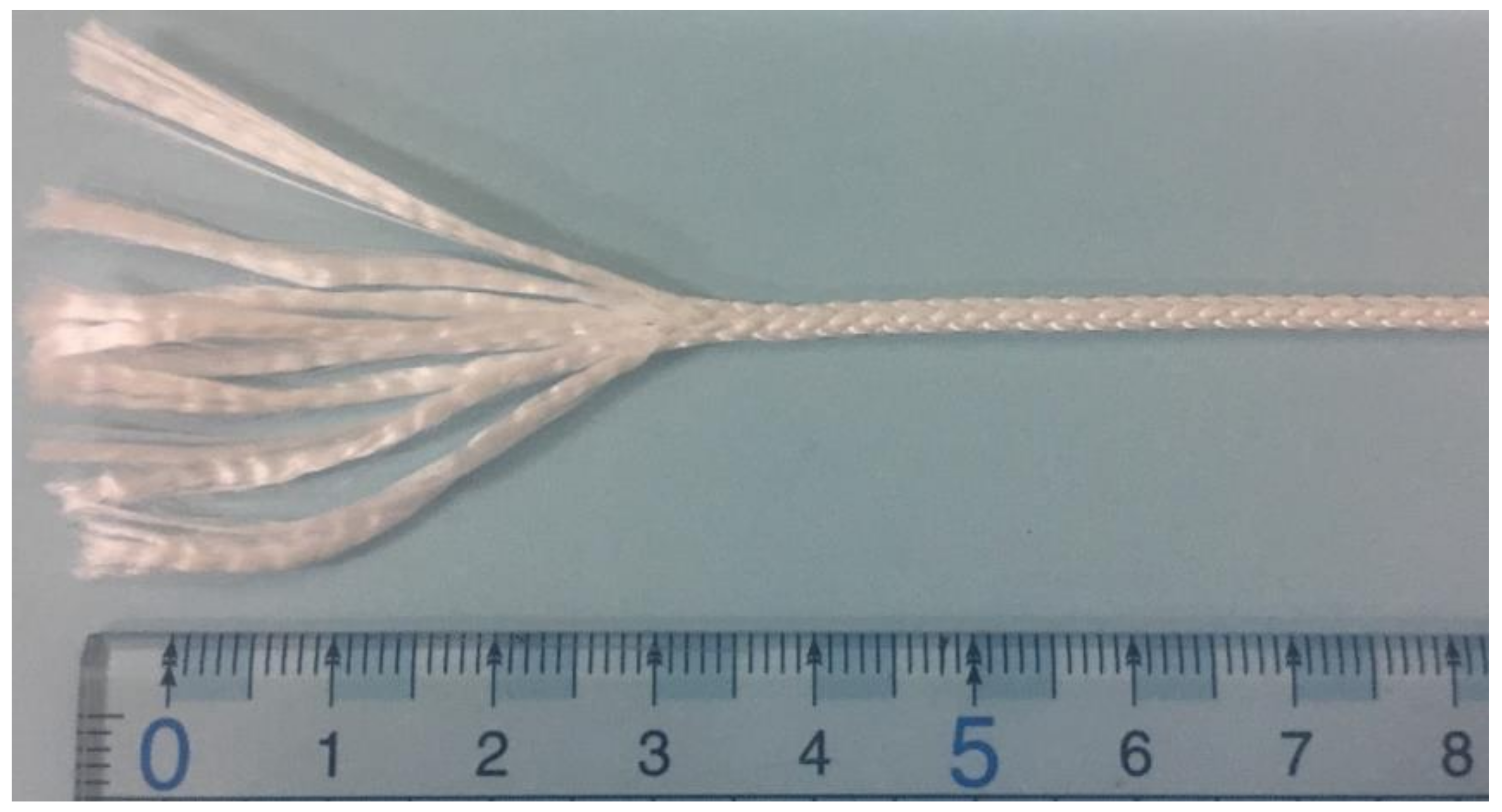
This study examines high modulus polyethylene (HMPE) rope. The HMPE rope was constructed by a braiding method using eight strands. Each strand was made from parallel fibers. Both the ropes and the strands were purchased from Hayami (Hayami Industry Co., Ltd., Shiga prefecture, Japan). The minimum break load (MBL) of the strands and ropes were 430 N and 1900 N, respectively. The MBL for the strands was experimentally determined, and the MBL for the ropes was obtained from the manufacturer. Linear density, expressed in grams per kilometer (tex = 1 g/1 km) is commonly used in textile engineering due to the presence of voids in the rope. In this study, the linear density of the strands was determined by cutting a strand to a length of 108 mm and weighing it (Shimadzu AX200). The linear density of the rope was determined by the same procedure but at a rope length of 43 mm.
Figure 1 shows the braided HMPE rope consisting of eight strands and
Table 1 summarizes the material properties of both the strand and rope.
In this study, we followed the standard of CI 1500 (Cordage Institute International Standard) in our experiment. Cyclic loading tests were conducted for strands and ropes to measure the longitudinal modulus. Experimental conditions are shown in
Table 2. The maximum load of the cyclic test was set to 20% of the MBL as this represents typical loads in practical applications [
6]. As shown in
Figure 2, the rope had a gauge length of 105 mm and was sewn at both ends to clamp it to the tensile testing machine (AG-I Shimadzu co., maximum load of 100 kN). The strain of the rope was measured by the non-contact method using a high-speed camera (Basler acA4600-10uc) with a resolution of 4608 × 3288 pixels. The change in the length between the two marked points (
Figure 2a), initially 43 mm apart, was measured by the camera during the test. The change in the braided angle and the diameter of the rope were also measured during the test. The camera was controlled to take pictures at the same time interval as the load measurements from the tensile testing machine. To improve the reliability of the results, the diameter and braided angle were measured 5 and 10 times, respectively, and each averaged. For the strand experiment, glass fiber reinforced plastic (GFRP) plates were attached at both ends of the strand with epoxy adhesive (3M Scotch-WeldTM DP460) to clamp with the grip of tensile testing machine (
Figure 2b). The strain of the strand was calculated using crosshead displacement of the tensile tester. Three samples of rope and strand were tested in this study and they were conducted at a crosshead speed of 1 mm/min. In this study, we did not change the crosshead speed since the viscoelastic effect was not taken into account because the stiffness varied with small range in 1.9% for strand and 5.0% for rope when the crosshead speed changes from 1 to 200 mm/min.
3. Suitable Unit for Stress and Modulus
The most suitable measurement unit for describing the stress and modulus of strands and ropes when applying CLT is one of the main topics of this study. As previously mentioned, the elastic modulus of ropes with a matrix have been predicted using CLT in several studies [
8,
9,
10,
11,
12,
13]. These studies use the unit of MPa to express stress and modulus.
It is well known that all synthetic fiber ropes are produced from many tiny fibers which are constructed into yarns or strands before they are twisted or braided into rope. As a result, the presence of voids (space between strands) is inevitable for all sizes of ropes. To account for voids when studying the mechanical properties of the rope, i.e., stress or modulus (MPa), the packing factor (
PF), defined as the cross-sectional area of strands over the cross-sectional area of rope, is generally introduced (Equation (1)) [
14,
15]:
where
is number of strands in the rope, and
and
are the cross-section and diameter of the strand and rope, respectively.
The
PF is generally used in analytical models to represent the reduction in stiffness of the rope due to the existence of voids. For example, Ghoreishi et al. [
15] accounted for
PF in their model by multiplying it with the stiffness of a virtual rope without voids for a multilayered fibrous structure. Thus, the stress–strain relationship of the rope can be described by Equation (2):
where
is stress in conventional unit (MPa)
is strain determined by ratio of rope displacement to initial length of the rope
is an estimated elasticity modulus without considering voids in the rope in the unit of (MPa).
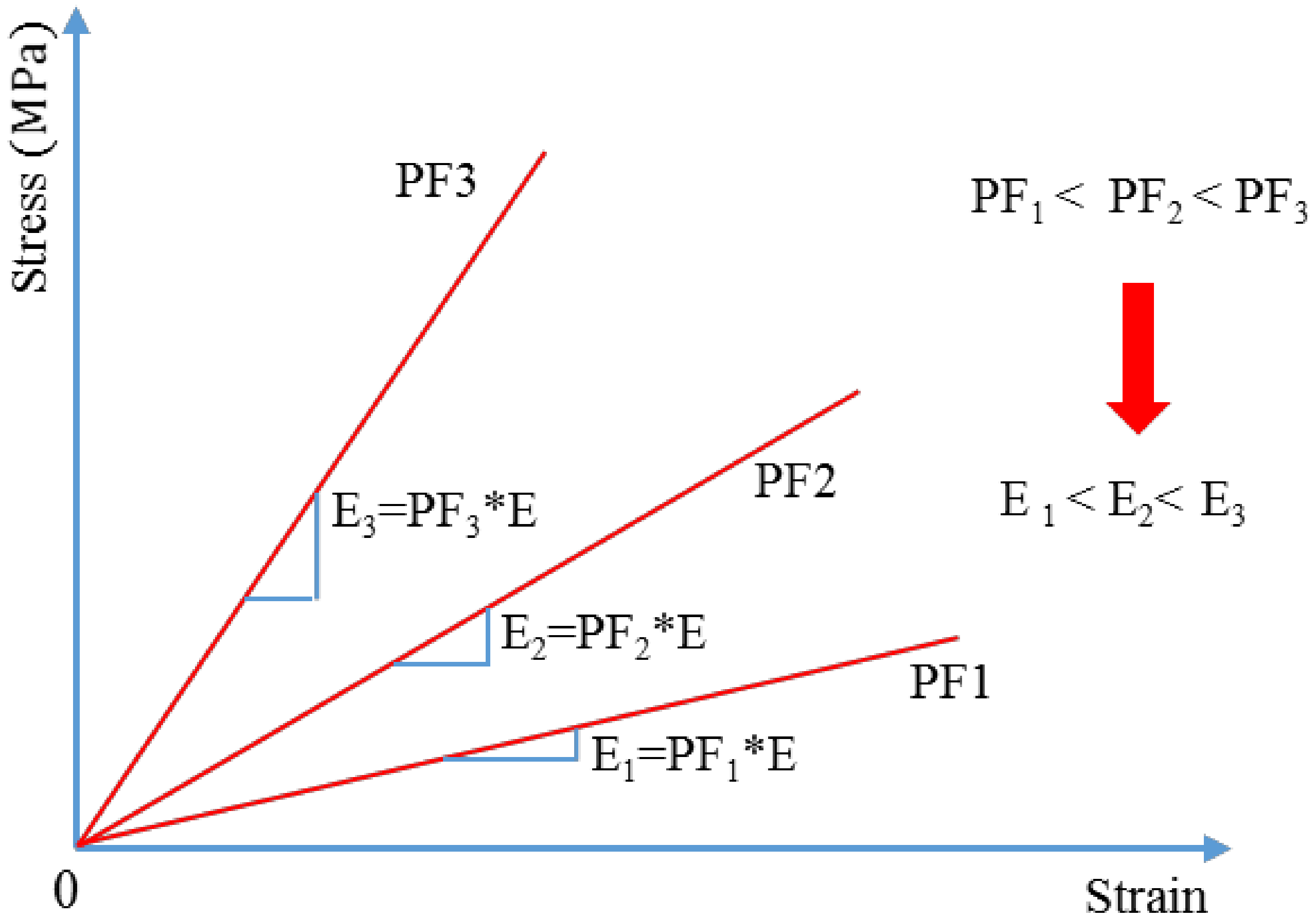
As demonstrated by Equation (2), when the
PF increases, the stress increases.
Figure 3 shows the relationship between the stress and strain of the rope with different PFs (PF
1 < PF
2 < PF
3), assuming
in Equation (1) is constant and
is varied due to changes in voids. Longitudinal modulus is changed by
PF as shown in
Figure 3. On the other hand, when the stress in
Figure 3 is replaced with load, the lines in the figure converge. This demonstrates that stiffness of the rope is independent from
PF and that
PF is introduced only for discussing stress and modulus with unit of MPa.
As the PF of rope without a matrix is easily changed during service, and is difficult to measure, these results show the limitations of using unit of MPa when discussing the modulus. Based on this, in the current study, the cross-sectional area of the rope is replaced by linear density, expressed in tex (1 tex = 1 g/km), when predicting the modulus using CLT. Conventional engineering stress and elastic modulus (expressed in MPa) are thus replaced by specific stress and modulus, respectively, in unit of N/tex. As tex is independent from PF, specific stress and modulus (N/tex) are also independent from PF. Because tex is based on the weight and length of the rope only. In the above discussion, only the change in voids in the rope is considered. PF is also changed by deformation of the strand, although the effect of the deformation is discussed in the next section, based on experimental data.
4. Experimental Results and Discussion
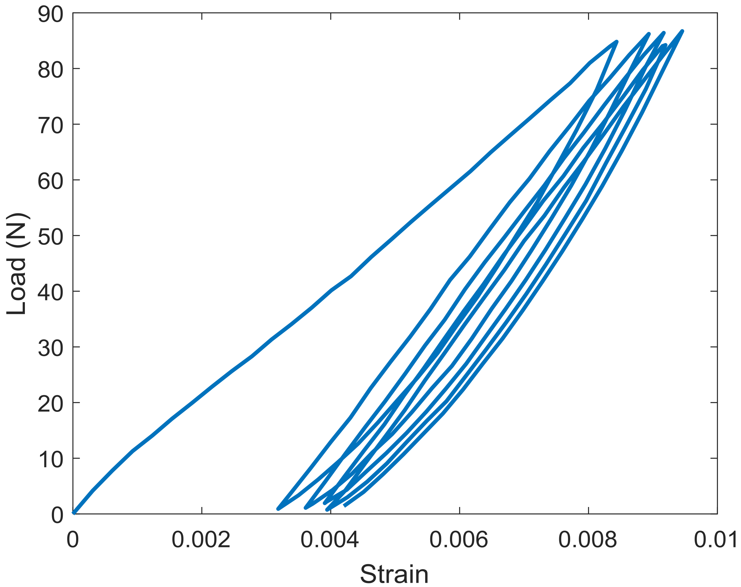
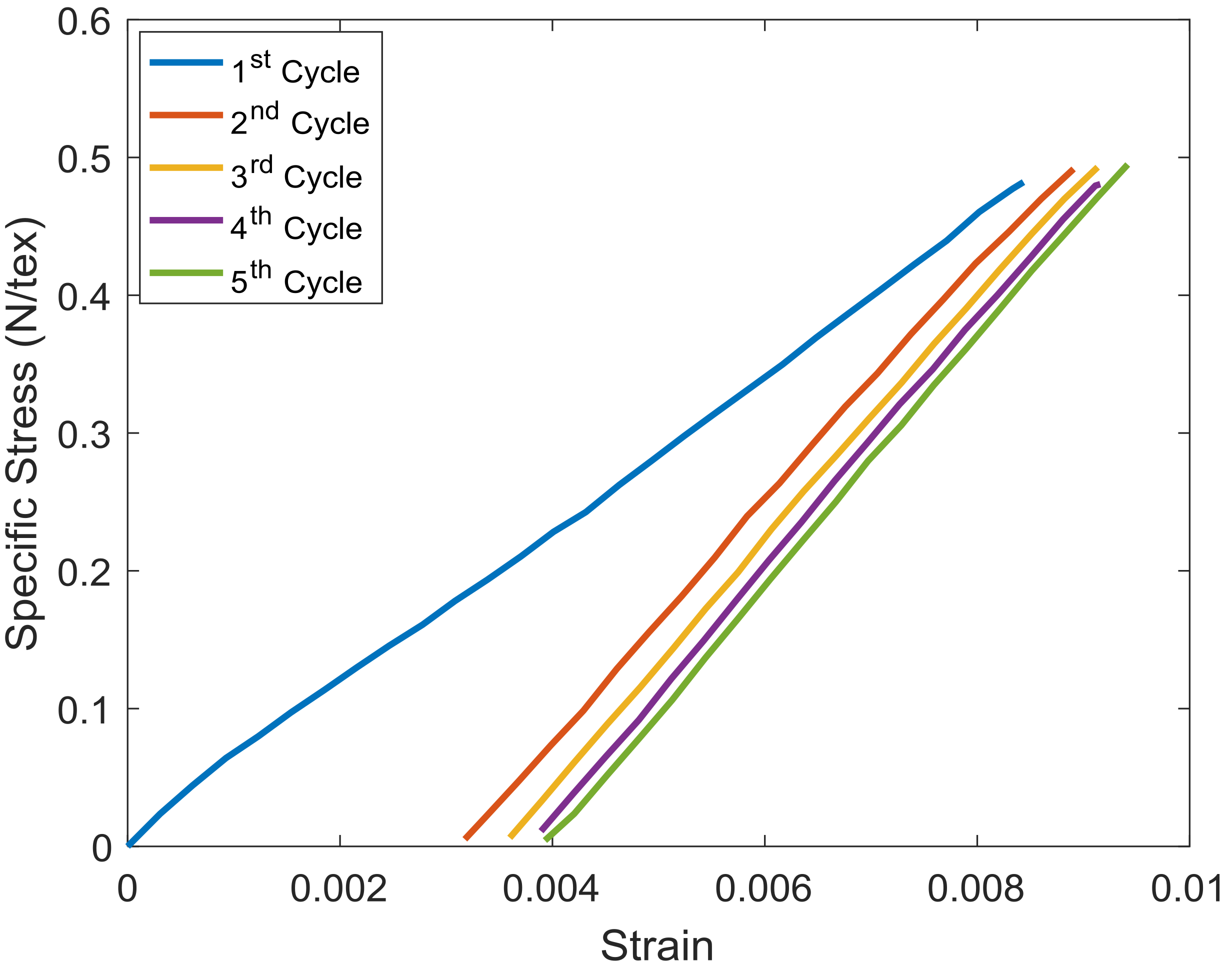
Figure 4 shows the results of five cyclic loadings of the strand. In this work, the unloading is omitted when discussing longitudinal modulus because of the buckling effect. During the cyclic loading test, the length and diameter of both the strand and the rope changed after each loading cycle. The change in the length led to a change in the linear density (tex). Thus, we recalculated a new linear density of both the strand and rope before each cycle by dividing the weight with new length. This increases the accuracy of the data and allows for separating discussion of the effects of strand modulus and strand angle to the rope modulus.
Figure 5 and
Figure 6 show the relationship between specific stress and strain of the strand and rope for the loading part of five cyclic tests. The longitudinal specific modulus (unit of N/tex) of the strand and rope in each cycle were calculated by fitting data. The specific modulus of the strand (cycles 1–5), and the rope (cycles 2–5) were determined using the data across the entire range of strain because the specific stress vs. strain graphs are almost perfectly linear. The specific modulus of the rope at the first cycle could not be determined since a non-linear relationship was observed between specific stress and strain. As mention in the previous section, three samples of rope and strand were conducted in the experiment and the average errors in longitudinal specific modulus from one sample to another are approximately 3% and 5% for strand and rope, respectively. Therefore, the results presented in this section are based on experimental data of the first test. The specific modulus of the strand and rope in each cycle are presented in
Table 3; values in parentheses indicate the specific modulus when the change of linear density with respect to the cycle numbers is not taken into account. The specific modulus of the strand largely changed from the first to the second cycle which may have been caused by the molecular alignment. After the second cycle, the degree to which the specific modulus changed was lessened. A similar trend was observed for the rope after the second loading, as the modulus gradually changed with the number of cyclic loadings.
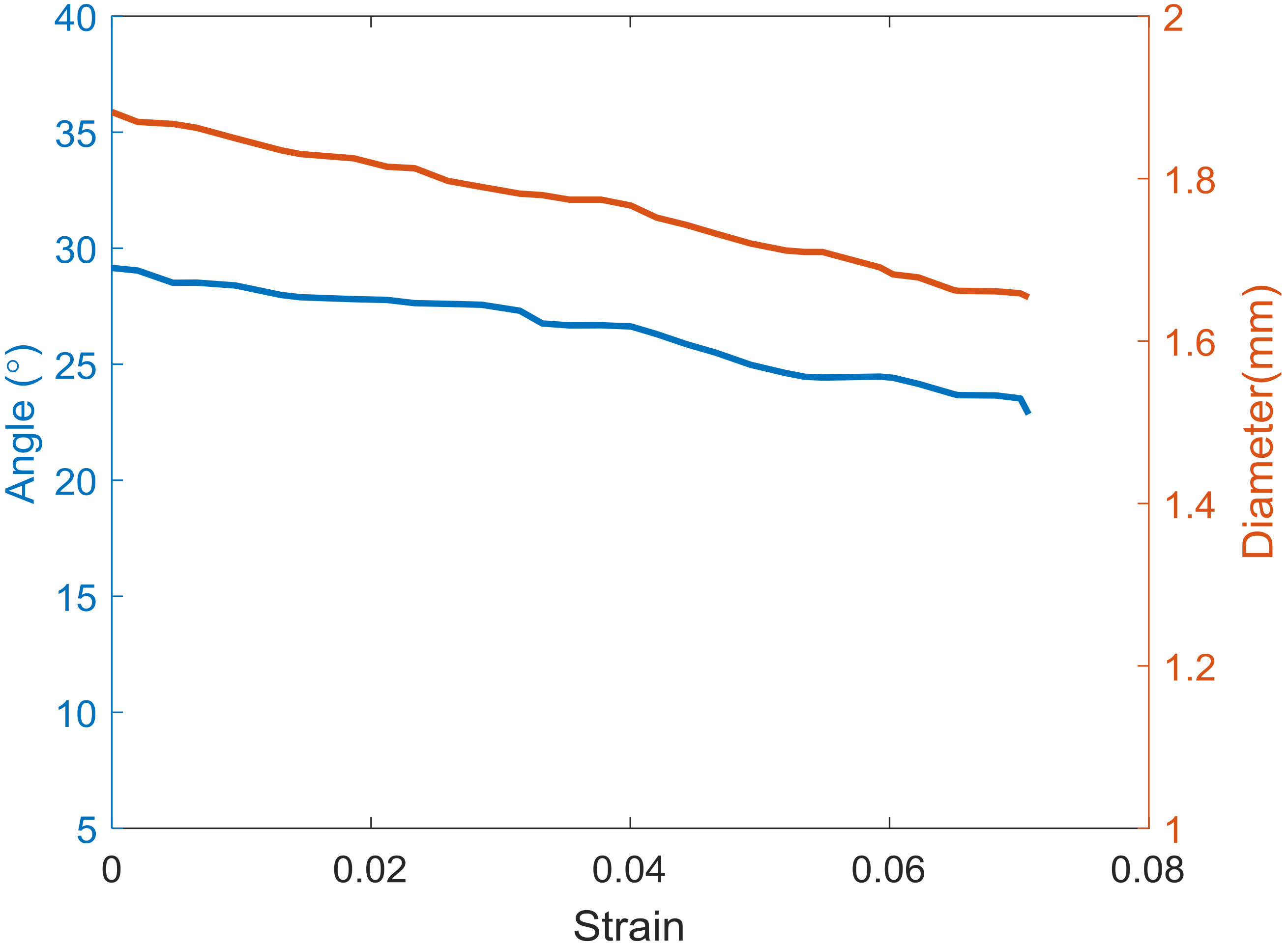
Figure 7 shows the measured braided angle and diameter of the rope at the first cycle. The angle and diameter decreased by approximately 7° and 0.23 mm, respectively, with strain. This result implies that the construction geometry of the rope changes significantly when the rope experiences the first cyclic loading.
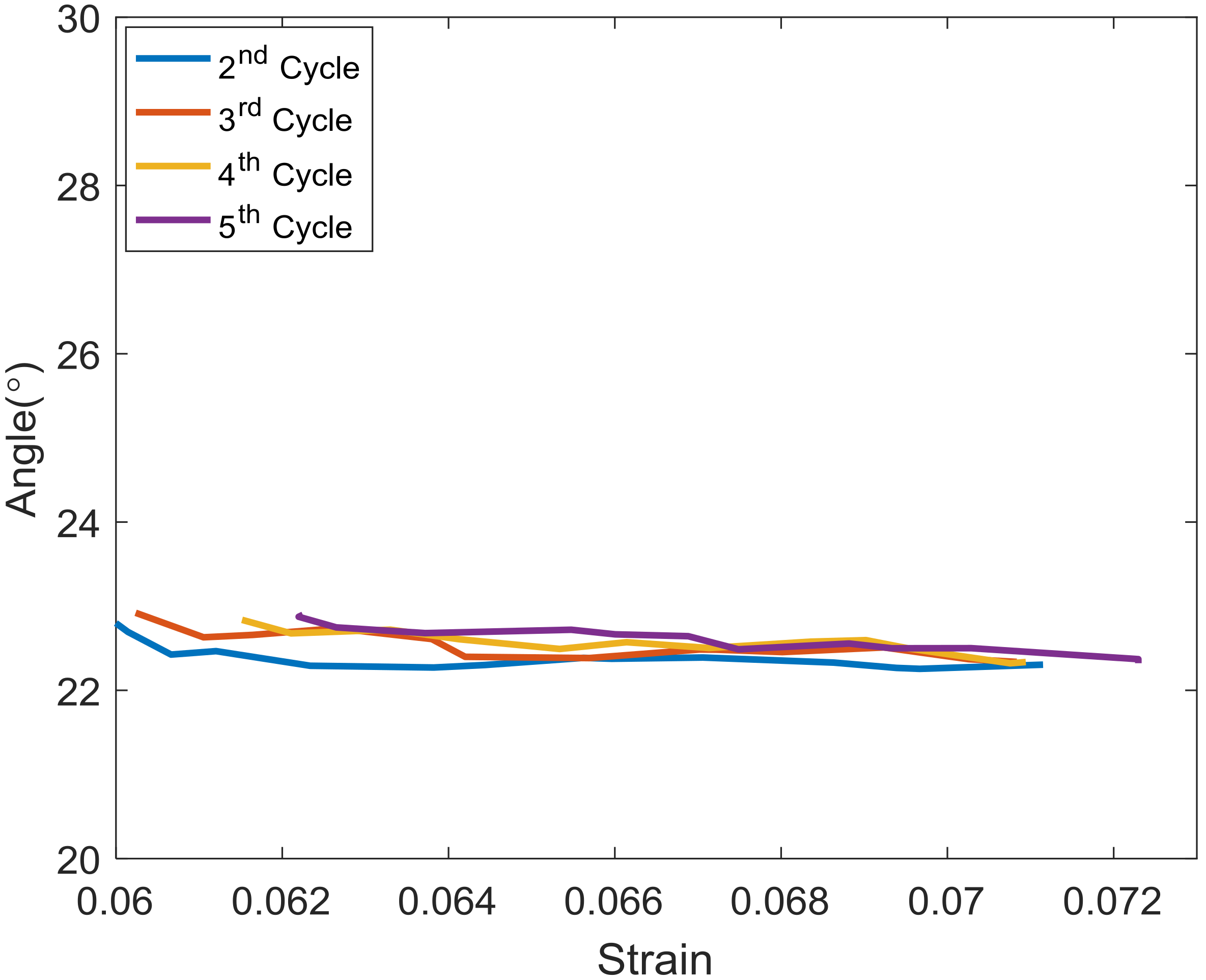
Figure 8 and
Figure 9 depict the change in angle and diameter of the rope, respectively, with strain, from the second to the fifth cycle. During these periods, both the angle and diameter of the rope changed less than during the first cycle and remained at near constant values. This means that the construction geometry of the rope does not change following the first cycle, with the same loading level, which probably resulted from the friction between fibers. These measured values are used to predict the specific modulus of the rope using CLT and to discuss the applicability of CLT when using the unit of N/tex.
Table 4 shows the change in linear density (tex) and cross-sectional area of the rope during the test. The change in tex denotes the change in length of the rope due to deformation (elongation). When the rope is extended (from L
1 to L
2) by deformation, the area of the rope is reduced (from A
1 to A
2). When the change in voids is ignored and there is a constant volume deformation, the ratio of A
1 to A
2 (or MPa
1 to MPa
2) becomes the same as L
1 to L
2 (or tex
1 to tex
2). The change in
PF caused by strand deformation influences the stress and modulus of the rope equally, whether MPa or N/tex unit are used. However, due to the difficulty in measuring the change in cross-sectional area of the rope separated from the void area, and the simplicity of measuring the change in the length of the rope, the unit of N/tex is preferable for examining the stress and modulus of braided ropes without a matrix. The changing ratio of tex and area for the first and second cyclic tests were 0.94 and 0.78, respectively. The value of 0.94 was only affected by deformation, and the value of 0.78 was affected by both the deformation and void change. As mentioned above, the effect of deformation is the same for tex and area, and the value of 0.78 can be calculated as 0.94 × 0.83 = 0.78. The value of 0.83 represents the change in voids. As the value of 0.83 is lower than 0.94, the main cause of changing area for the braided rope at the first loading is the change in void space in the rope. As the effect of void changes can be neglected when the unit of tex is used, this result again shows the appropriateness of using unit of tex for this type of rope.
5. Analytical Model of the Rope
The analytical model in this study is based on the unit cell in the rope, using experimental data of the strand and the braided angle of strand in the rope. For simplicity, the following assumptions were made:
Nonlinearity of material was not taken into account
Undulation effect of the strand was not considered for simplicity and due to complicated structure and small size of the rope. According to Neitzel et al. [
16], the errors of elastic modulus in the plain and twill weave laminates were reduced around 10.6% and 5.3% respectively when the undulation of the yarn was taken into account in the CLT. Therefore, this approximate model is valid when the error of several % is within the allowable range.
Loading was assumed to be purely axial
The effect of Poisson’s ratio was not taken into account
The unit cell was assumed as plane stress and homogeneous anisotropic elastic material.
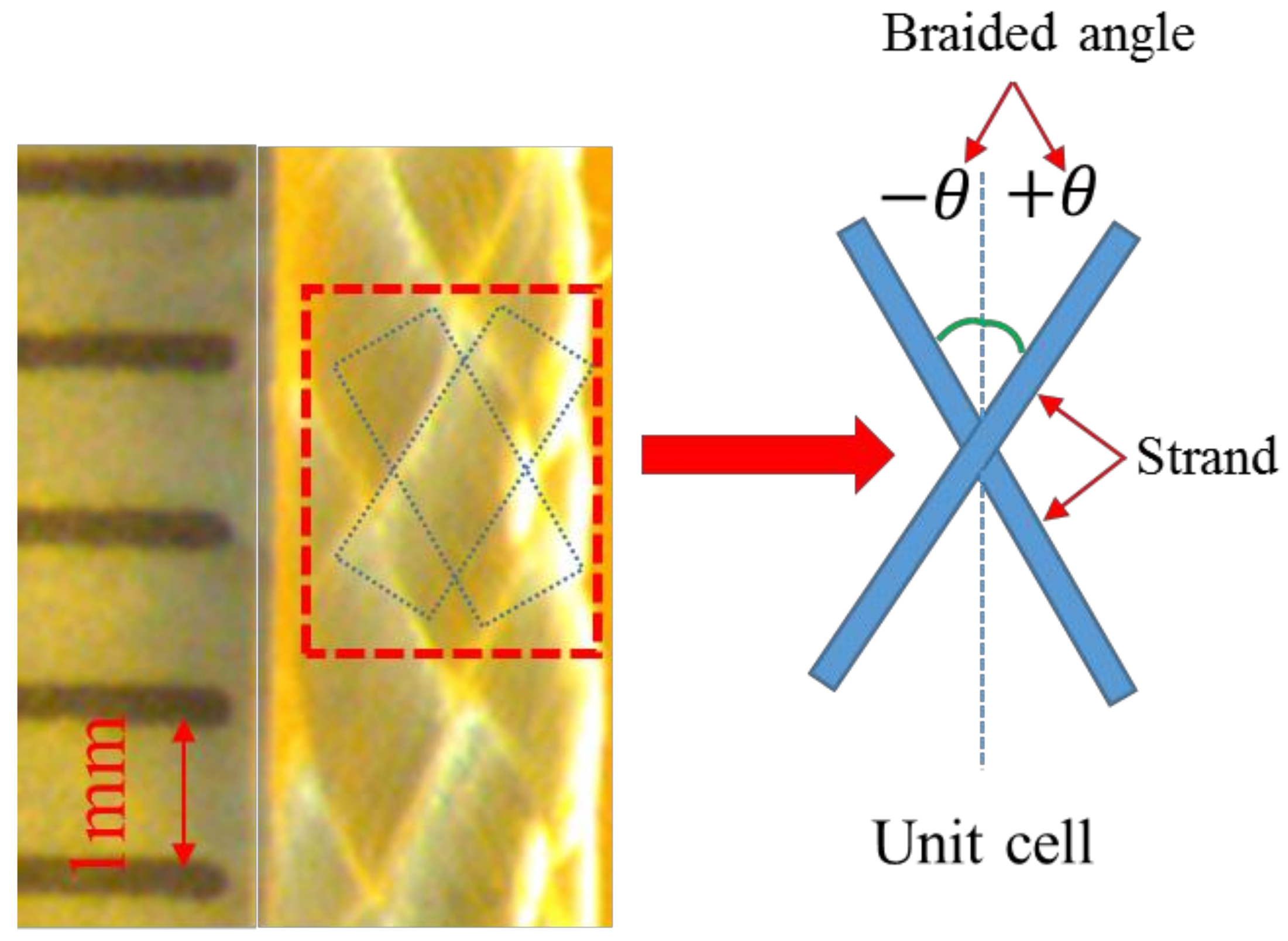
Figure 10 shows the braided HMPE rope in which a unit cell consists of two strands at the angle of
and
with respect to the axis of the rope. By applying CLT, the stress–strain relation is given in Equation (3) [
17]:
where
,
, and
are the stress, stiffness matrix (MPa), and strain matrix in the plane stress, respectively. However, as mentioned earlier, when the cross-sectional area is replaced by linear density, all components of the stress, stiffness matrix are expressed in N/tex. The components of the stiffness matrix in Equation (3) are presented in Equation (4) as follows:
where,
: Longitudinal specific modulus in the axial direction (N/tex);
: Transverse specific modulus in the transverse direction (N/tex);
: Poisson ratio in the longitudinal and transverse directions;
: Shear specific modulus (N/tex).
When the loading is applied purely in the longitudinal direction and the Poisson’s ratio is neglected, the stiffness matrix
in Equation (3) becomes:
The stiffness matrix of the strand in the unit cell which is rotated by angle
and
can be derived from Equation (6):
with
being the braided angle and the transformation matrix, respectively:
Thus, the equivalent of the stiffness matrix in the unit cell can be determined from Equation (8):
As we assumed the unit of modulus as N/tex, packing factor does not need to be considered. Therefore, the specific elastic modulus of the unit cell is the components of the equivalent stiffness matrix in Equation (8). However, this work focuses only on longitudinal specific elastic modulus:
6. Analytical Results and Discussion
The specific modulus of the rope was predicted from the specific modulus of the strand in the axial direction and the braided angle of the strand using CLT. Because five cyclic loadings were conducted, five specific modulus and braided angles were needed to predict those moduli. The braided angles were selected as the beginning of each cyclic test. This means that at the first cycle input angle is the angle before testing, and input angle for second cycle is the angle at the end of the first cycle, and so on. These input parameters were substituted into Equations (5)–(9) and the results obtained are summarized in
Table 5. The predicted longitudinal specific modulus (
) of the unit cell has the smallest value at the first cycle due to the smallest modulus of the strand (
) and the largest braided angle (
). From the second cycle, the moduli remained at nearly constant values, exhibiting a change rate of only 5.21%, as the modulus and angles of the strands constituting the rope were almost stable. The predicted longitudinal specific modulus (
) of the unit cell were compared with that of the rope obtained from the experiment.
Table 6 shows the comparison results for the second to fifth cyclic tests. Moduli obtained from the prediction were larger than moduli of the rope measured via experimentation. This difference mainly has been caused by strand undulation in the rope; this was neglected in this study for simplicity, due to the complexity of the rope structure. However, it is important to note that both the predicted and experimentally-measured specific modulus remained nearly constant after the second loading cycle when the strand modulus and slope were not changing very much (
Table 5). This result shows that the specific modulus and the slope of the strand are dominant to the modulus of the real rope, similar to our simplified model.
With respect to the longitudinal modulus for the first cyclic test, as the relationship between specific stress and strain of the strand at the first cyclic test is linear (
Figure 5), the strand modulus (
) is constant during the test. On the other hand, the relationship between the specific stress and strain of the rope at the first cyclic test (
Figure 6) is nonlinear; this is considered to be influenced by the change in the angle of the strand (
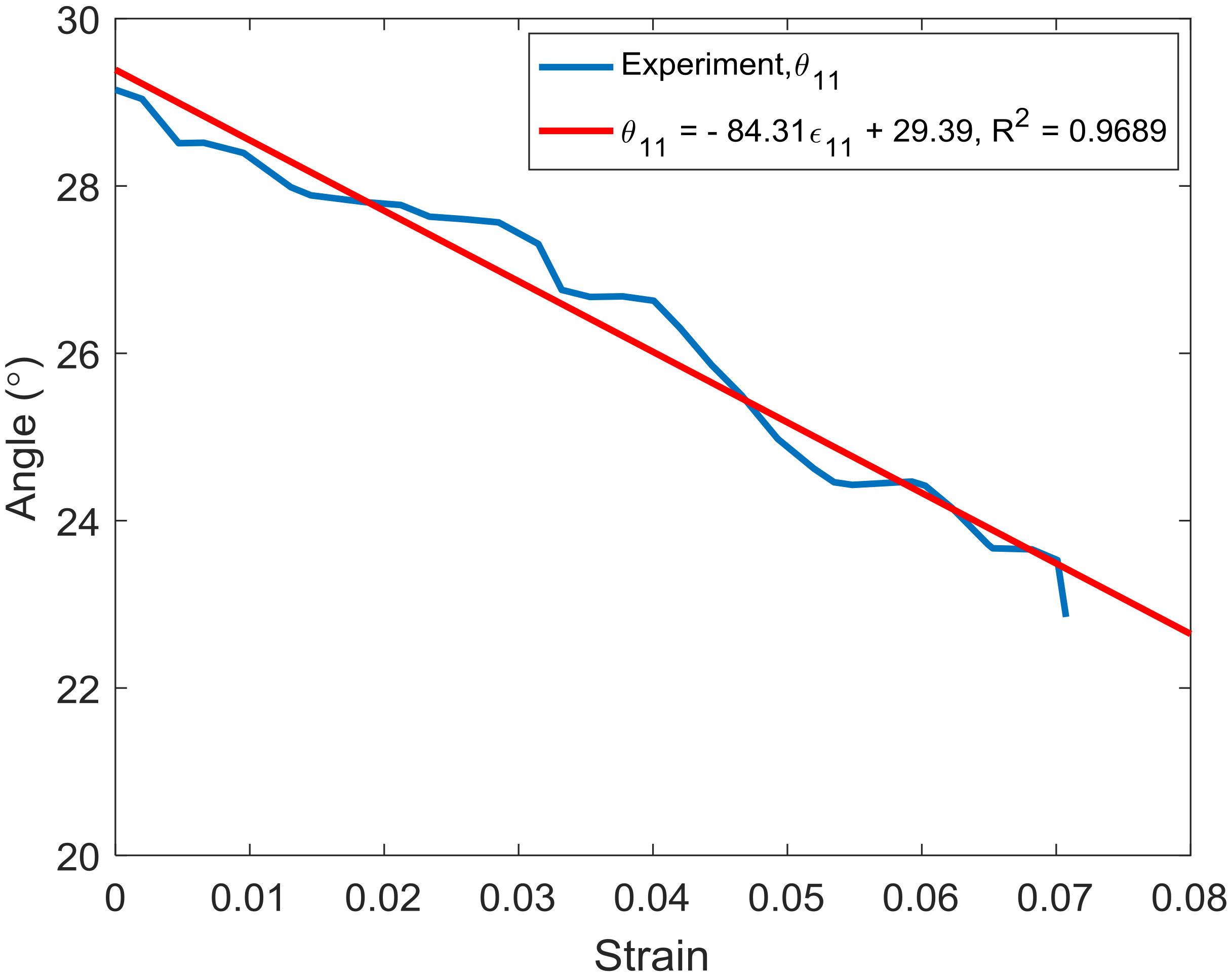
) since the strand modulus is constant. As the angle of the strand changed with strain in a linear manner (
Figure 7), a linear fit of the data was conducted.
The result of the data fitting is shown in
Figure 11. As a result, the braided angle-strain relationship is described using Equation (10):
where
,
,
, and
are the angle, strain, and constant values, respectively. As mentioned above, strand modulus (
) is constant during the first cyclic test. When substituted into Equations (5)–(9), the specific modulus of the rope at every braiding angle in the first cyclic test (
) (
Table 5) can be obtained. The data shows that the specific modulus of the rope at the first cyclic test is linear with the braided angle in this limited range. This linear relationship between the specific modulus and braided angle can be expressed as follows:
where
,
,
represent the longitudinal specific modulus, braided angle, and constant value, respectively.
In this study, we used unit of N/tex for the modulus and stress and did not need to consider
PF, which is a function of strain, in Equation (2). Thus, the relationship between specific stress and strain can be expressed as follows:
where
,
,
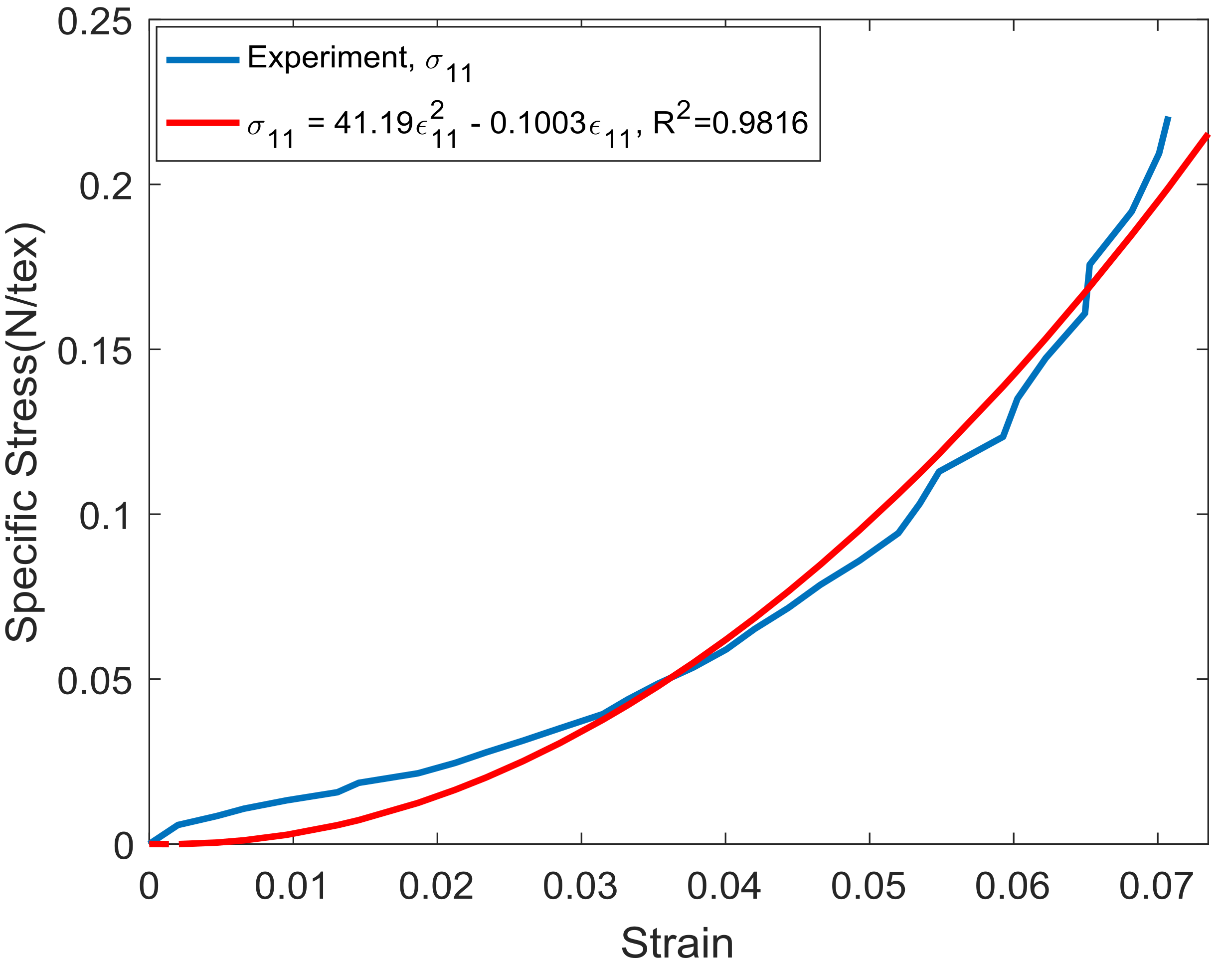
are the specific stress, specific modulus, and strain at the first cyclic loading of the rope, respectively. By substituting the Equations (10) and (11) into Equation (12), the final relationship of specific stress and strain of the rope at the first cycle was obtained, as shown in Equation (13):
where
are the constant values.
Based on Equation (13), the specific stress of the first cycle in the analytical model has a second degree order with respect to strain. By referring to the specific stress vs. strain in
Figure 6 for the first cyclic test, it can be seen that the trend-line of specific stress vs. strain has a second order polynomial function (
Figure 12). Therefore, the trend-line of the specific stress and strain in both the experimental and analytical test were similar during the first cyclic loading. This result proves that our simplified model for predicting the modulus can be used for qualitative discussion. This result also shows the advantage of using the N/tex unit, since when MPa units are used for the stress and modulus, Equation (13) becomes Equation (14). Then the relationship between stress
and strain
becomes complicated since the
PF should change with strain:
By introducing the unit of N/tex to the CLT, the relationship between the stress and strain of the rope can be explored in a more simplified manner. Future studies will be conducted to examine other effects, such as undulation of the strands.


