Artificial Circulatory Model for Analysis of Human and Artificial Vessels
by
 ,
,
Andrzej Polanczyk
1,2,* ,
,
Markus Klinger
2, 
Josif Nanobachvili
2,
Ihor Huk
2 and
Christoph Neumayer
2 1
Faculty of Process and Environmental Engineering, Lodz University of Technology, Wolczanska 213, 90-924 Lodz, Poland
2
Department of Surgery, Division of Vascular Surgery, Medical University of Vienna, Spitalgasse 23, 1090 Wien, Austria
*
Author to whom correspondence should be addressed.
Appl. Sci. 2018, 8(7), 1017; https://doi.org/10.3390/app8071017
Submission received: 13 May 2018
/
Revised: 6 June 2018
/
Accepted: 15 June 2018
/
Published: 22 June 2018
(This article belongs to the Section Applied Biosciences and Bioengineering)
Abstract
:Background: Ex vivo computer controlled circulatory reactors are advantageous for the investigation of circulatory systems. So far, most of the models have dealt with laminar or pulsatile flow. This study aimed to monitor blood vessel and vessel graft compliance continuously under physiological flow in real time. Methods: Human common iliac arteries and silicon tubes served as interposition grafts. Changes in wall diameter and displacement were analyzed. The artificial circulatory system (ACM) presented an “artificial heart” able to simulate various ejection pressures, ejection volumes (EV), and frequencies of pulsation (FP). ACM was validated by comparing medical data reconstructed with the 2D-speckle-tracking-technique (2DSTT). Results: Silicon tubes were more rigid compared to iliac arteries, as changes in diameter were approximately 48% lower (0.56 ± 0.007 mm vs. 0.83 ± 0.016 mm, p < 0.0001, for EV = 70 mL and FP = 60 min−1). Wall displacement was 2.3-fold less pronounced in silicon tubes (1.45 ± 0.032 mm vs. 5.79 ± 0.043 mm for iliac arteries (p < 0.0001)). FP and EV did not further increase differences in wall displacement between both types of grafts. There were no significant changes between results gathered from ACM and 2DSTT. Conclusions: The ACM was successfully validated by 2DSTT with the use of selected grafts. It may become a useful tool to investigate different types of vascular grafts.
1. Introduction
Cardiovascular diseases are the main causes of morbidity and mortality worldwide with the lifetime risk of more than 60% [1]. Therefore, both in vivo and ex vivo research is performed to find new strategies to protect the circulatory system [2]. However, in vivo experiments, performed mainly in animal models, may not directly reflect the changes in the human body, while clinical studies could raise ethical issues. On the contrary, ex vivo experiments have less limitations as they may be performed on tissues or on primary cells [3,4]. In addition, recent biomedical research is directing the delivery of cells with biomaterials for the therapeutic advancement and regeneration of tissues [5,6].
Basically, the systemic circulation can be regarded as a network of blood vessels, namely arteries and veins, connected to a pump (the heart), that transports oxygen and nutrients within the body [7]. The pulsatile character of blood flow in the arterial system causes a strong and recurrent stretch of arteries’ walls that may result in its damage, especially in the case of pre-existing alterations such as atherosclerosis [8]. However, wall stress and wall strength cannot be directly measured in vivo [9]. Moreover, vessels’ wall compliance is of the utmost importance for the clinical outcome, as graft angulation presents a risk factor for shear stress-induced, platelet-mediated thrombosis [10]. Besides, it has recently been shown that longitudinal compliance exceeds circumferential compliance in an ex vivo porcine model [11].
Various models have recently been developed to understand vascular biology, Among those are ex vivo tissue culture systems described to evaluate vascular responses in relation to various biomechanical and biochemical factors [12,13]. So far, few efforts have been taken to exploit the potential of ex vivo vessel bioreactors towards a high-fidelity ex vivo replication of the hemodynamic factors affecting arterial wall behavior in an artificial environment. Ex vivo vessel culture systems for replication of the hemodynamic factors enable investigation of flow and pressure conditions [2,14]. They may also offer the possibility to indicate the effects caused by wall shear stress [15,16], as well as generated by the pure pulsatile pressure [17,18]. However, most of the models published so far deal with the laminar flow of “artificial arteries” [19,20] or graft preservation solutions [21].
The aim of the study was to design and construct a dedicated ex vivo computer controlled circulatory bioengineering reactor to monitor vascular tissue responses in real time and under various physiologic conditions. This artificial circulatory model (ACM) aimed to combine the advantages of various models described so far and allows a unique insight into vascular adaptation to a combination of stimuli. The device was next tested with human common iliac artery and silicon tubes to verify its usefulness in analyzing mechanical parameters of tested interposition grafts.
2. Materials and Methods
2.1. Experimental Setup
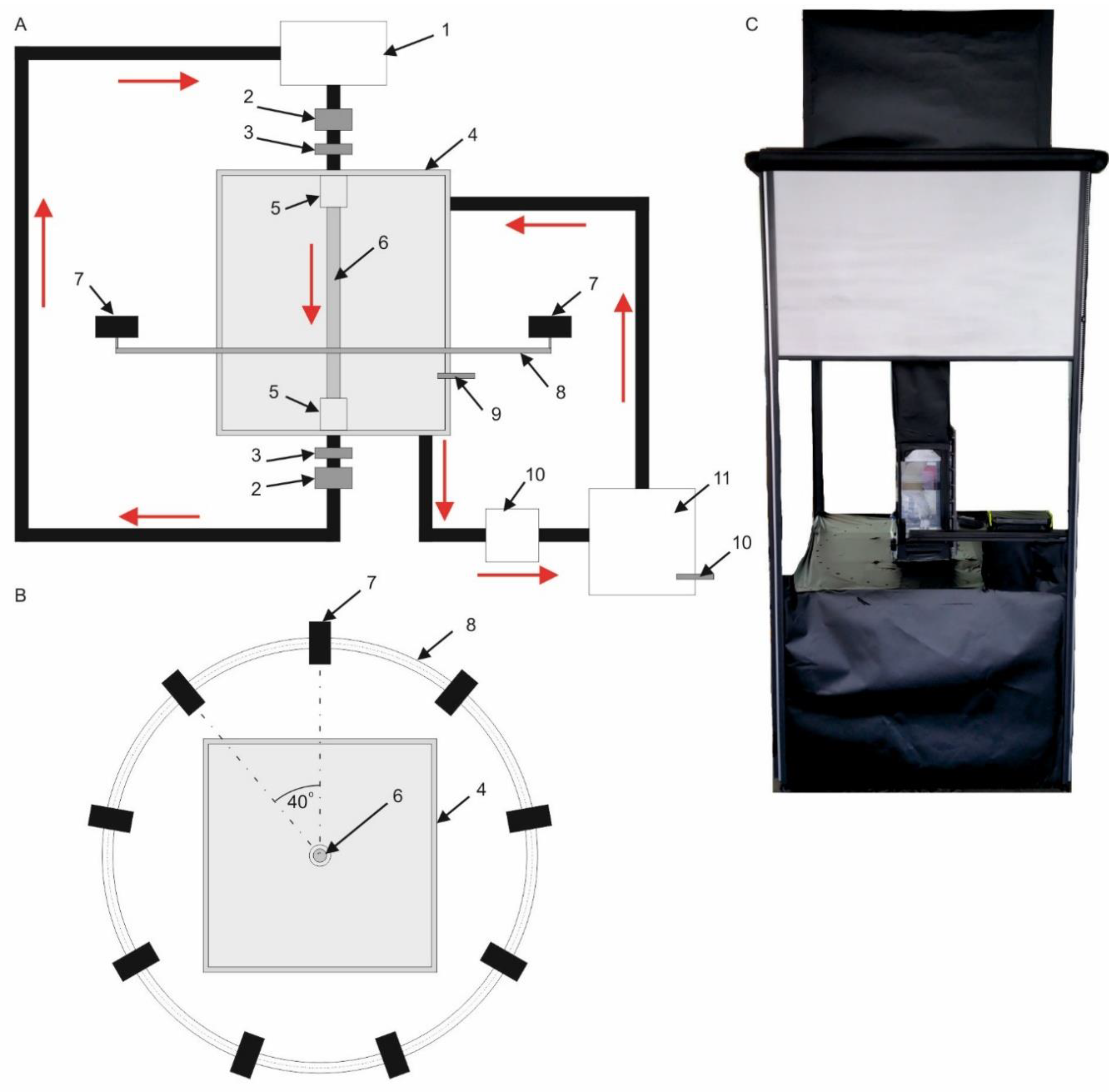
Analysis of vessels’ mechanical behavior required reconstruction of blood hemodynamics in different physiological and pathological conditions. Therefore, an ACM was designed and built for computational projection of vessels’ structures under different flow conditions (Figure 1A).
The main part of the ex vivo perfusion system was a vessel reactor represented by the transparent, rectangular vessel chamber made of plexy (Figure 1A4) that was able to keep the temperature constant. Temperature was monitored with an installed temperature sensor (Figure 1A9) [22]. Analyzed grafts (Figure 1A6) were placed in a non-commercial fluid mimicking blood’s rheological properties, which consisted of 60% distilled water and 40% glycerol (density of 1.2 g cm−3 and viscosity of 4.8 × 10⁻³ Pa·s) [23]. Circulation of non-commercial fluid between the vessel chamber (Figure 1A4) and fluid chamber (Figure 1A11) was provided by a pump (Figure 1A10). To prevent media leakage and allow the graft’s interposition, dedicated vessel stabilizers were applied (Figure 1A5). The pulsating character of the flow was achieved by a moving plager placed in a stainless-steel corpus called an artificial heart (Figure 1A1) that regulated ejection pressure, ejection volume, and frequency of pulsation. These parameters were controlled by an electrical engine connected to the computer. Therefore, each time, a specified amount of medium supplies the analyzed vessel. Moreover, hemodynamic parameters, e.g., flow/velocity, pressure were monitored with the use of ultrasound flow meters (Figure 1A2) and pressure sensors (Figure 1A3). To set realistic inlet conditions at the inlet of analyzed vessels, the artificial heart was designed and programmed. It mimicked the blood hemodynamic as we previously described [24]. Technical specification of applied sensors included: 0.024–60 L/min ± 2% (ultrasound flow meters, made by Bamo), 0–6 bar ± 0.5% (pressure sensor, made by Wika), and 0–40 ± 0.01 °C (temperature sensor, made by Wika). Furthermore, to simulate the internal pressure that exists within the abdominal cavity, the vessel chamber was filled with non-commercial fluid mimicking blood at a constant temperature of 37 °C.
A dedicated supervisory control and data acquisition (SCADA) system was developed with the use of LabView 2011 software (National Instrument, Austin, TX, USA), and applied for the artificial heart, flow meters, temperature and pressure sensors, and for the control of a vision acquisition system (VAS) (Figure 1B). The VAS system included nine cameras (Figure 1B7) placed on an aluminum circular profile (Figure 1B8), parallel to the floor to provide capability of horizontal movement. The size of an image pixel of the real object was 0.00035 m. To increase the accuracy of vision acquisition, cameras were able to move with 0.17 rad. (10 deg.) steps in both sides at the range of 0.70 rad. (40 deg.) A SCADA was combined with a portable working station Dell Precision M6400 with the following parameters: four core Intel CPU (2.4 GHz), 4 GB RAM (1333 MHz), and 500 GB SSD HD.
The flow was reconstructed by means of the following parameters: pulsating character of flow (FP) and different ejection volumes (EV) of non-commercial fluid per one cycle. Initial conditions for the process were as follow: FP: 60, 75, 90, 105, and 120 min−1; and EV: 70, 85, 100, and 115 mL.
Analysis of the vessel’s mechanical behavior was focused on wall spatial deformation ability. Two parameters were considered: change of the diameter Dd (Equation (1)) and wall displacement Wd (Equation (2)).
Dd = Ddynamic(x,y,z) − Dstatic(x,y,z),
Here, Dd–vessel’s diameter dilatation, (mm); Dstatic(x,y,z)–vessel’s diameter recorded under static conditions, (mm); and Ddynamic(x,y,z)–maximal diameter of vessel recorded under dynamic conditions, (mm).
Wd = Wdynamic(xp’,yp’,zp’) − Wstatic(xp,yp,zp),
Here, Wd–vessel’s wall displacement, (mm); Wstatic(xp,yp,zp)–spatial configuration of vessel’s wall in relation to its central axis recorded under static conditions; xp,yp,zp–spatial coordinates of tracked point p positioned on the surface of analyzed vessel, (mm); Wdynamic(xp’,yp’,zp’)–spatial configuration of the vessel’s wall in relation to its central axis recorded under dynamic conditions; and xp’,yp’,zp’–spatial coordinates of tracked point p positioned on the surface of the analyzed vessel, (mm).
Moreover, the ultrasound 2D-Speckle tracking technique (2DSTT) (GE Vivid 7, GE Healthcare, Pittsburgh, PA, USA) was applied for the analysis of the vessel’s diameter change, with the use of a workstation equipped with software for strain analysis (EchoPac PC, GE Medical System, Pittsburgh, PA, USA).
2.2. Analyzed Material
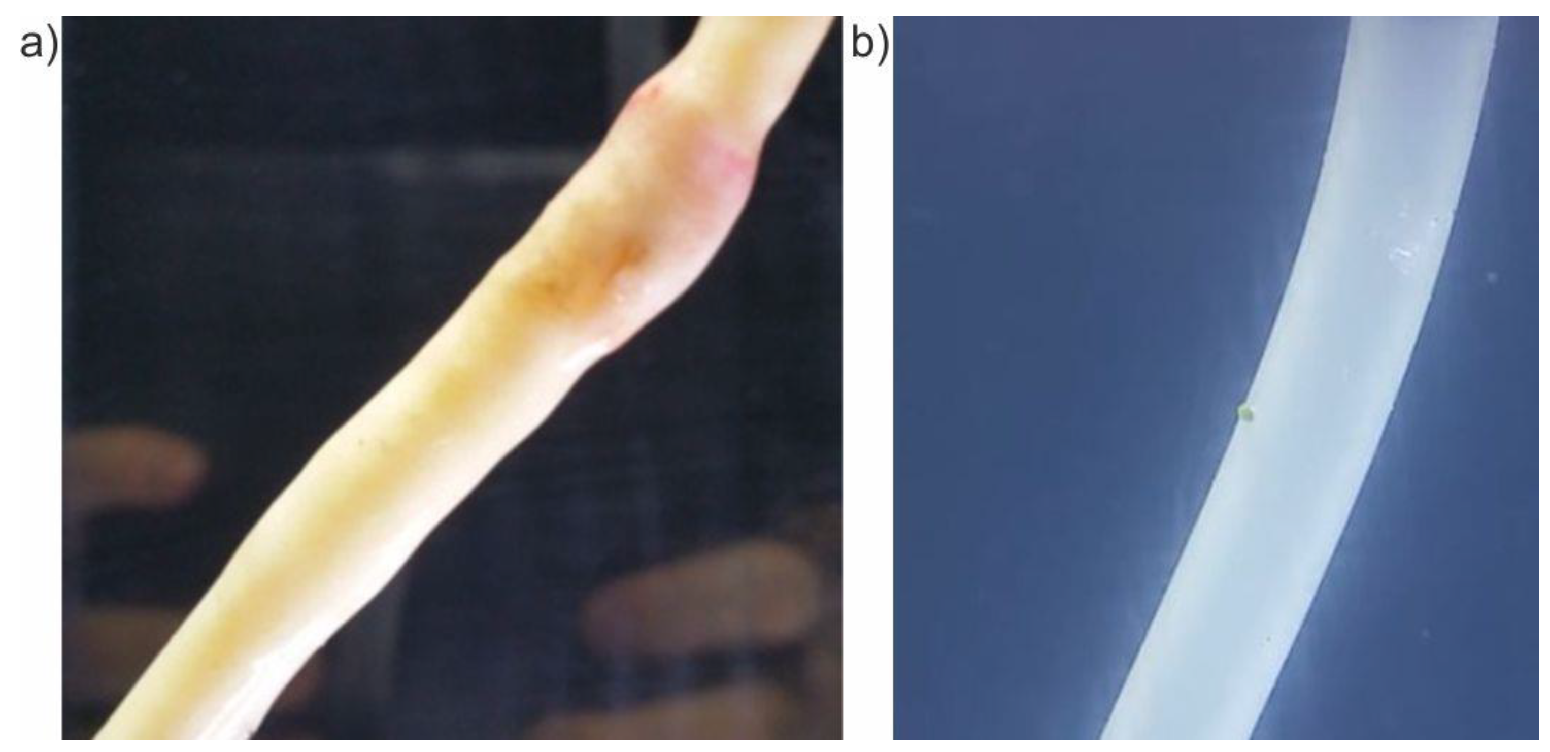
The designed device was tested using human common iliac arteries harvested from five male organ donors (mean 50 ± 10 years) at the Medical University of Vienna between 2016 and 2017. The experiments were performed no longer than 24 h after being harvested from the donor organ. Changes of diameter and wall displacement of iliac arteries were investigated and compared with silicone tubes (100 mm length and 8 mm diameter, made by Tubes International) imitating the artificial vessel, which served in our study as the “negative control” (a reference sample) (Figure 2). Analysis comprised iliac arteries of the same length (100 mm) and diameter (8 mm). The study was approved by the local Institutional Review Board (2069/2012) of the Medical University of Vienna.
First, to verify the ACM and VAS, the flow was reconstructed with the following parameters: pulsating character of flow (FP) and different ejection volumes (EV) of non-commercial fluid per one cycle. Initial conditions for the process were as follows: FP: 60, 75, 90, 105, and 120 min−1; and EV: 70, 85, 100, and 115 mL. With the use of 2DSTT, we analyzed if the vessel’s wall movement registered with VAS mimics wall changes registered with 2DSTT. Next, to standardize the results gathered with ACM, we had to verify if changes in vessel diameter registered by the ACM system reflect changes in the vessel registered during a patient’s examination. Therefore, we used 2DSTT and compared five iliac arteries tested with ACM with data from five healthy patients performed with 2DSTT for the same type of arteries and for the same hemodynamic conditions as used for ACM. To standardize the results, we tested vessels (for ACM and healthy patients) under the following conditions: FP (75 min−1 and 90 min−1) and EV = 70 mL. Finally, medical data was compared with ACM results performed for the same hemodynamic conditions.
2.3. Statistical Analysis
Statistical analysis was performed using Statistica12.0 (Tulsa, OK, USA). Data were presented as mean ± SD. Moreover, the Bland-Altman method was applied to analyze the agreement between 2DSTT and ACM data. Spearman’s correlation rho analysis was used in addition. Comparisons between analyzed groups were made using the U Mann Whitney test after verifying normality and variance. Data were considered as significantly different when p < 0.05, unless otherwise noted.
3. Results
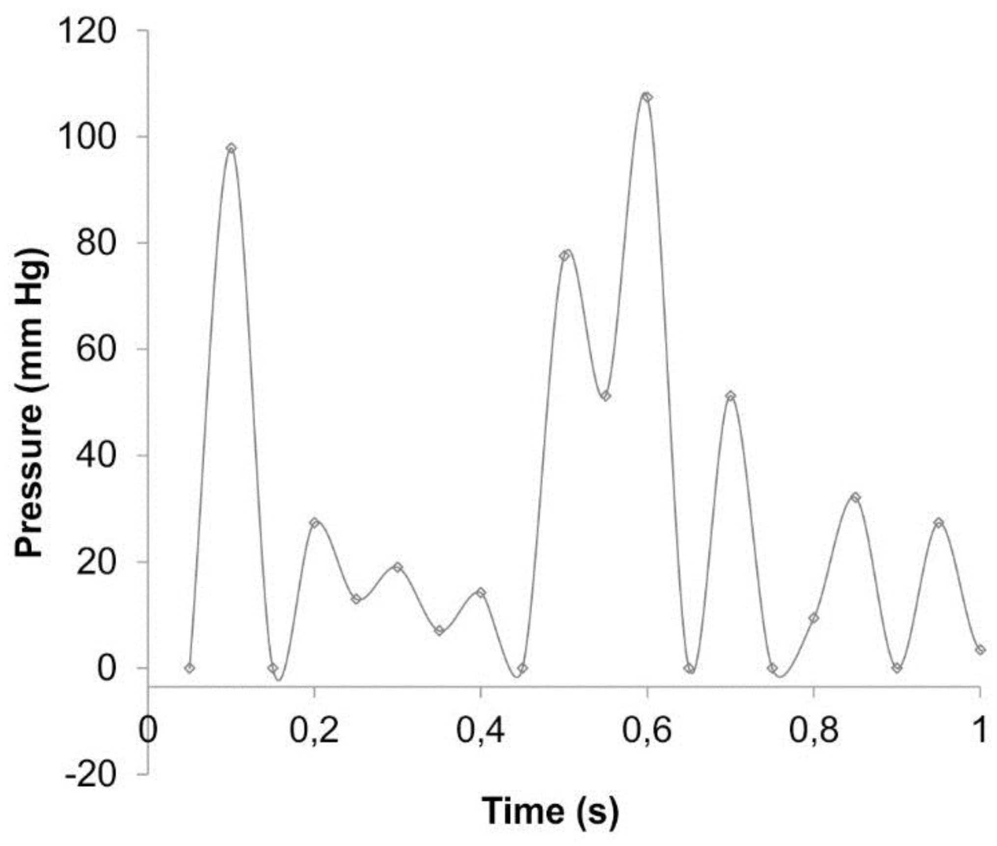
With the use of ACM, we could monitor and investigate the iliac arteries response under various physiological conditions in real time. Figure 3 presents an example of the pressure profile as a function of time including 10 s of cardiac cycle. The mean luminal pressure under the various experimental conditions was equal to 120 mmHg.
First, we analyzed the flexibility of the iliac arteries reflected as changes of spatial configuration and defined as a change of diameter Dd and wall displacement Wd for different EVs and FPs. The flexibility of the tested iliac arteries was compared with the flexibility of silicon tubes that served as negative controls.
3.1. Change of Diameter Dd
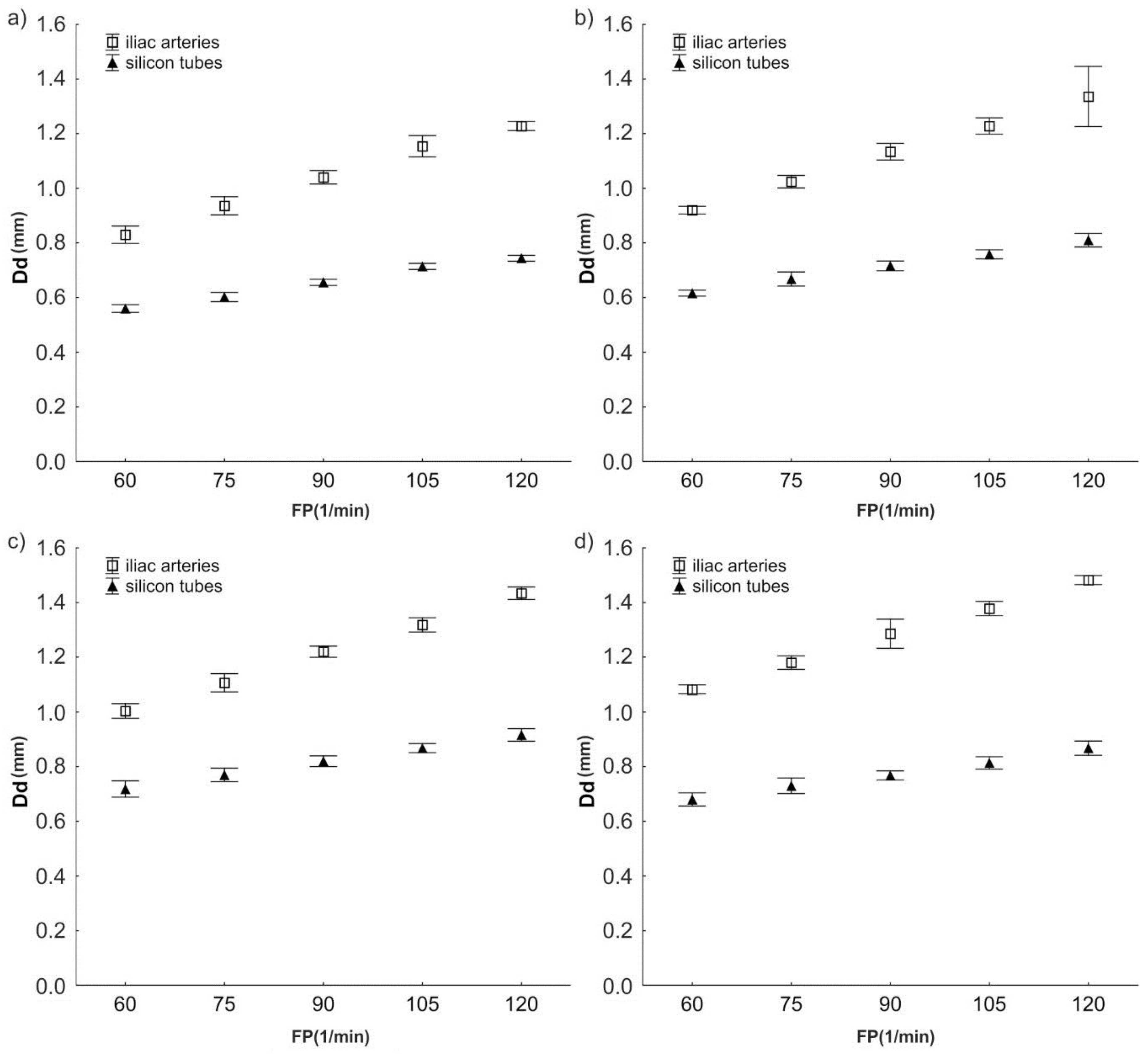
The analysis of diameter changes indicated that when EV was 70 mL and FP was 60 min−1, the mean of Dd for iliac arteries was 0.83 ± 0.016 mm (Figure 4a–d). The mean Dd for silicon tubes was 0.56 ± 0.007 mm, which was approximately 48% lower (compared to the iliac arteries (p < 0.0001)) (Figure 4a–d).
Similarly, when EV was 115 mL and FP was 120 min−1, the mean of Dd for iliac arteries was 1.48 ± 0.008 mm (Figure 4a–d). The mean Dd for the silicon tubes was also about 62% lower than the mean Dd for the arteries (0.92 ± 0.011 mm; p < 0.0001).
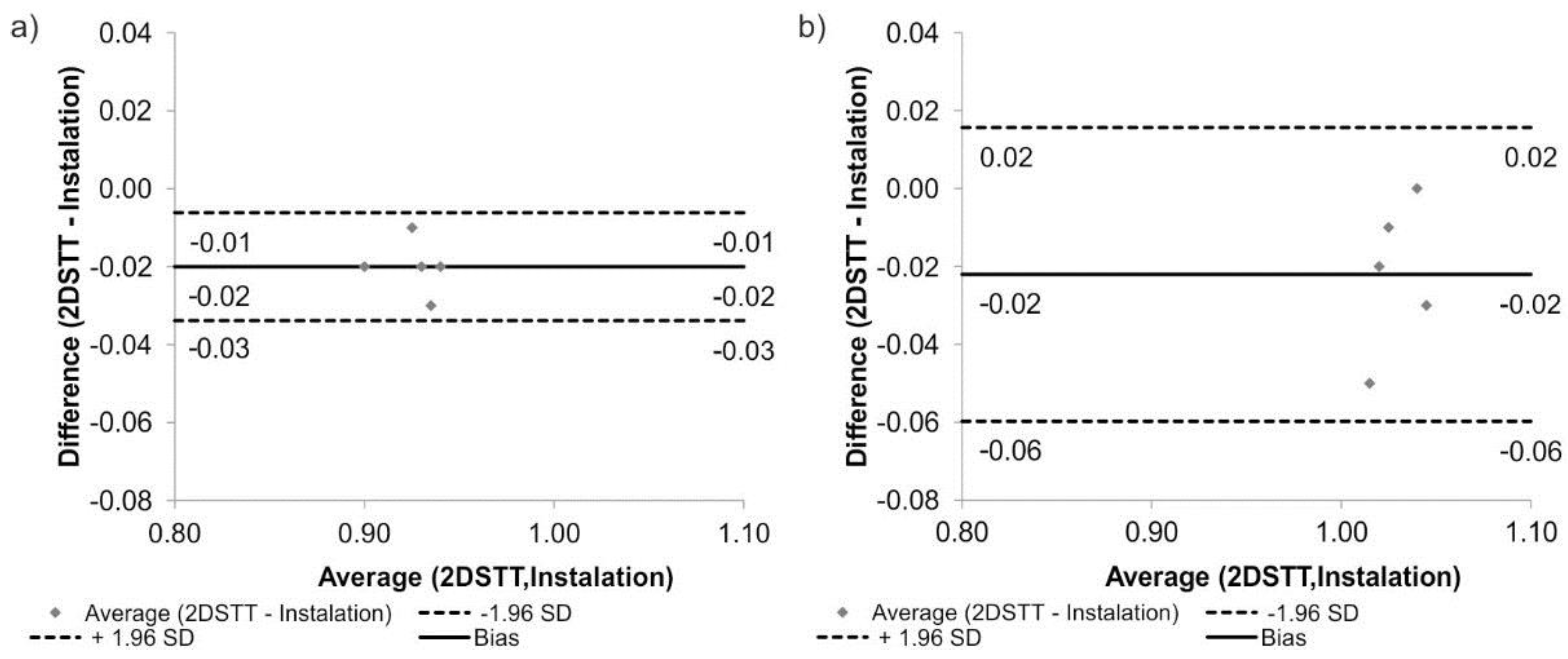
Next, the experimental results regarding vessel flexibility (Dd) were verified with 2DSTT data. There were no significant changes between results gathered from ACM and 2DSTT. The mean Dd for the iliac arteries for FP = 75 min−1 was 0.94 ± 0.017 mm when calculated with ACM and 0.90 ± 0.018 mm when calculated with 2DSTT (p = 0.083). Similarly, the mean Dd for the FP = 90 min−1 was 1.00 ± 0.024 mm for ACM and 1.04 ± 0.012 mm for 2DSTT (p = 0.063). Additionally, according to Bland-Altman analysis of the iliac arteries, for FP = 75 min−1, the difference between ACM and 2DSTT was equal to 0.02 mm for the range equal to 0.04 mm (Figure 5a), while for FP = 90 min−1, it was 0.02 mm for the range equal to 0.08 mm (Figure 5b).
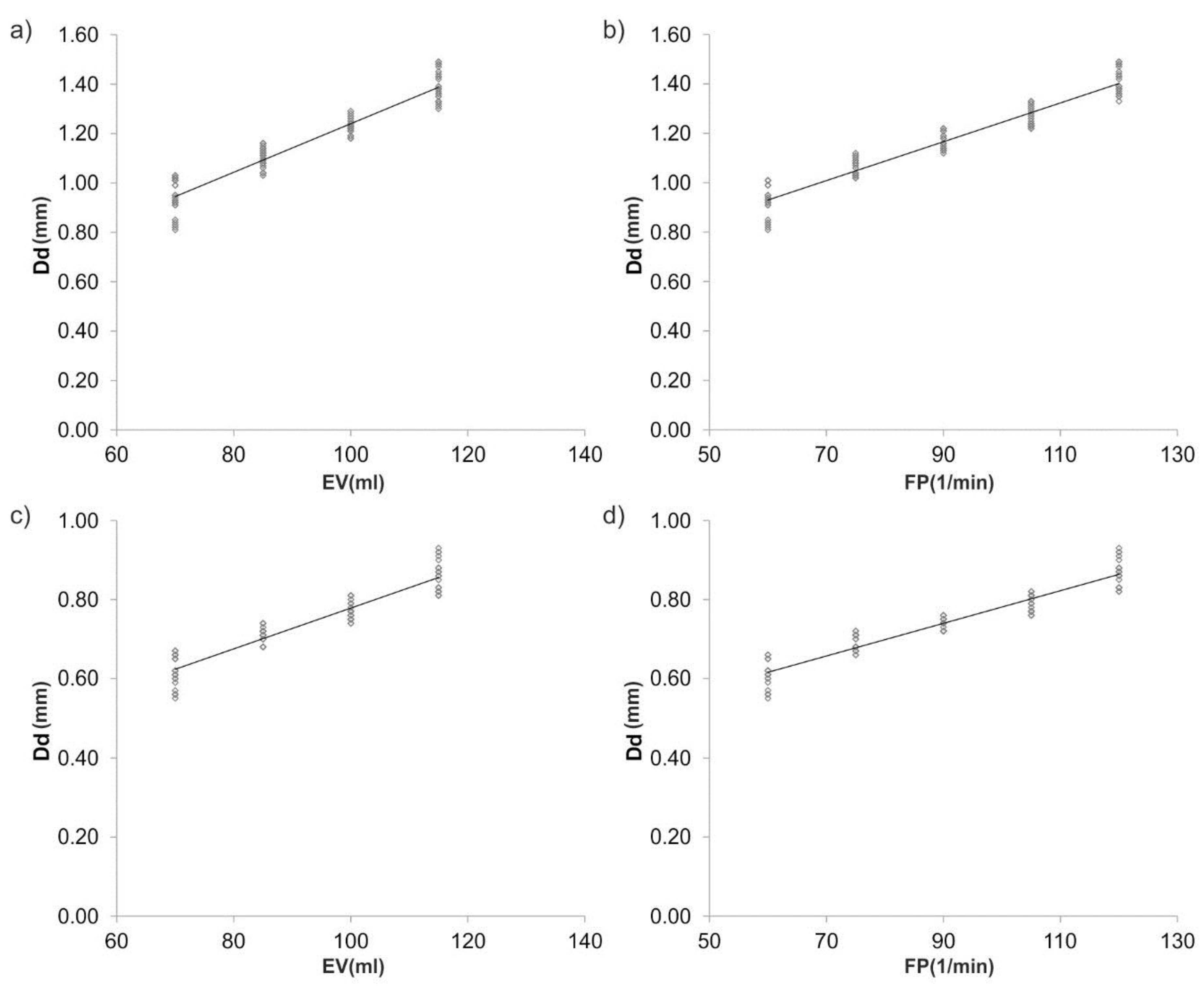
Furthermore, Spearman’s rank correlation coefficients were determined between Dd and hemodynamic parameters (Figure 6a–d). There was a positive correlation between Dd and EV for the iliac arteries (rho = 0.964; p < 0.05) and Dd and FP (rho = 0.923; p < 0.05).
3.2. Wall Displacement Wd
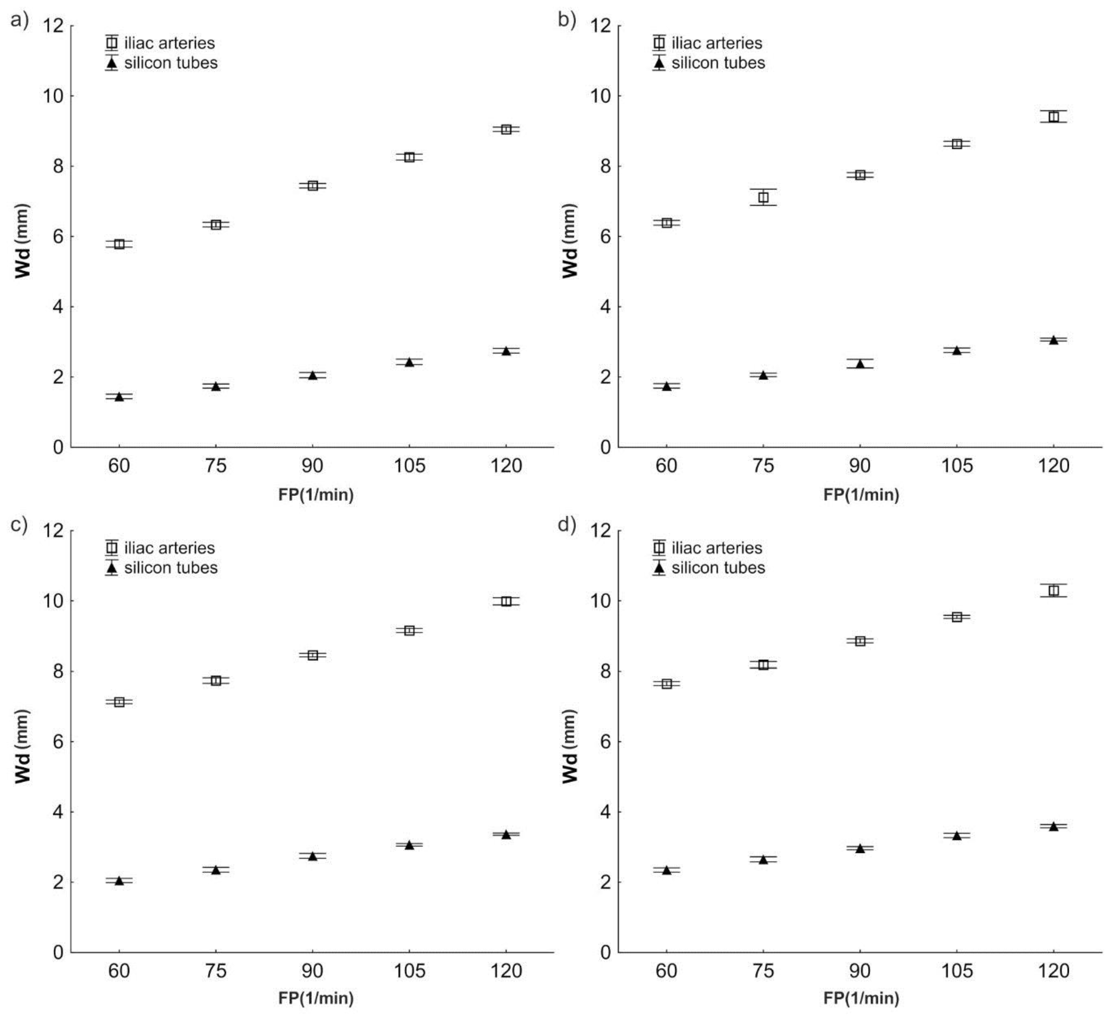
The analysis of wall displacement indicated that for the iliac arteries, an increase of EV from 70 mL to 115 mL and FP from 60 min−1 to 120 min−1 caused an increase in Wd from 5.79 ± 0.043 mm to 10.30 ± 0.089 mm (Figure 7a–d). Similar changes in Wd were observed for the silicon tubes (from 1.45 ± 0.032 mm to 3.60 ± 0.024 mm) (Figure 7a–d). However, the wall of the silicon tubes showed a twice as low change in displacement as iliac arteries. Furthermore, with an increase of FP and EV, no significant increase of differences in Wd values between iliac arteries and silicon tubes was observed (p > 0.05).
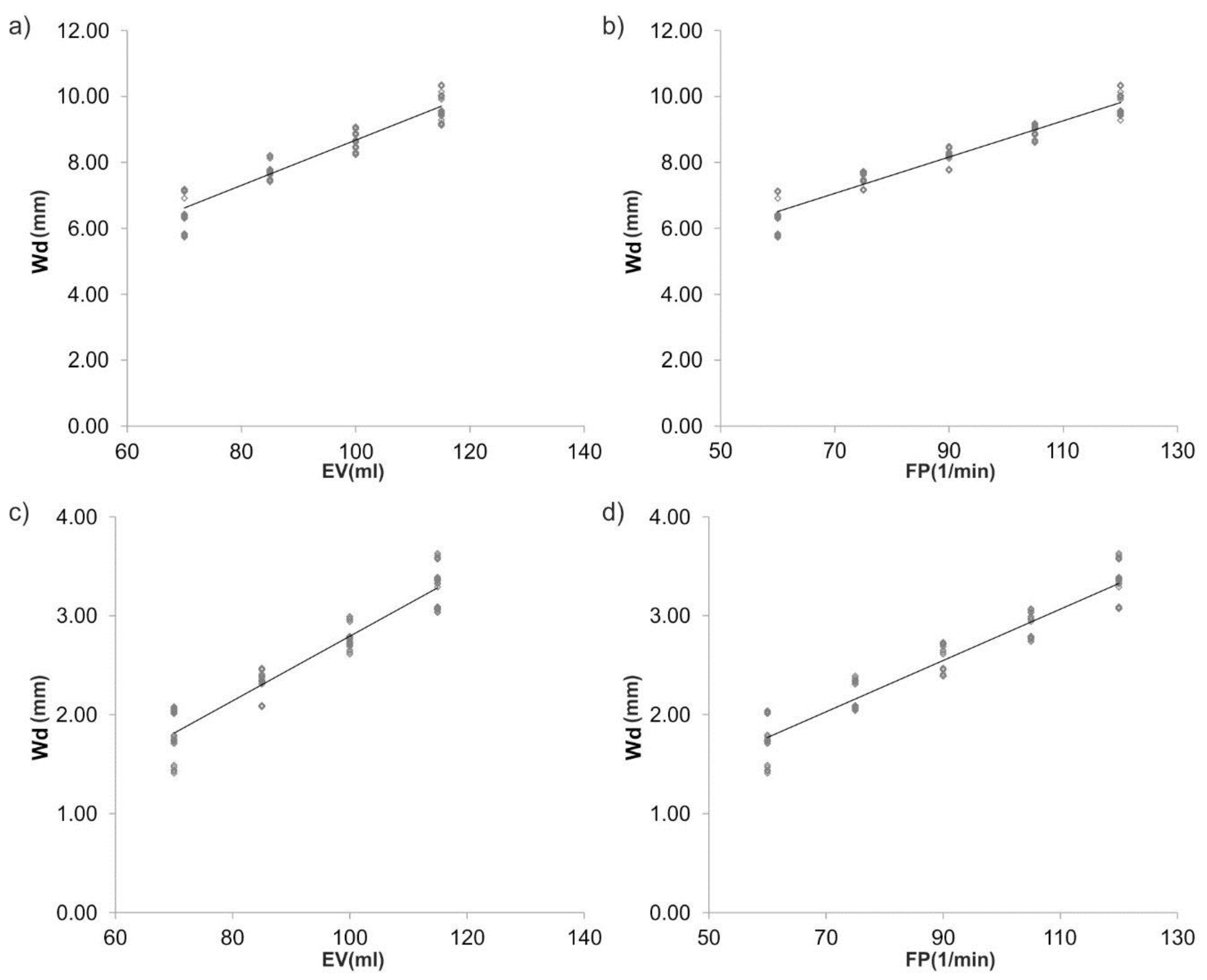
In addition, there was a positive correlation between trends in hemodynamic parameters and Wd; with the largest increase in Wd in the group of EV for the iliac arteries (rho = 0.976; p < 0.05; Spearman’s rank correlation coefficients). A similar trend was observed for the group of FPs where the largest increase was observed for the iliac arteries (rho = 0.968) (Figure 8a–d).
4. Discussion
The present study introduces an ACM, which was designed and built to mimic the human circulatory system. With the use of an artificial heart, it was possible to simultaneously reconstruct different ejection volumes, frequencies of pulsation, and ejection pressures. The system comprised a transparent, rectangular, container for vessel placement (the vessel chamber) that acts as an incubator by maintaining a constant temperature and constant CO2 concentration. Moreover, because in the human body there is a higher pressure within the abdominal cavity, our device was designed to maintain an interior pressure that acts on the vessel. Finally, with the use of our vision system, we monitored changes in the spatial configuration of the analyzed vessels, which have been validated with clinical data.
Our results demonstrated that simulation of physiological conditions of blood hemodynamics in an ex vivo bioengineering reactor requires vascular grafts, as the application of silicon tubes resulted in lower diameter changes and a decrease of wall displacement compared to human common iliac arteries. To the best of our knowledge, our ACM is the first model capable of analyzing these factors, because the existing vascular bioreactors lack the monitoring of mechanical properties of investigated vessels so far. Moreover, to date, there are no data presenting the application of vision systems for 3d projection of a vessel’s wall behavior after placement in bioengineering reactors.
An ex vivo vessel culture system has been built for the replication of hemodynamic factors in the coronary circulation by Piola et al. [12,14]. This system is at least somehow comparable to our ACM. However, effects of altered flow conditions have only been investigated in human saphenous veins after coronary artery bypass grafting [13]. Mundagi et al. also reported on an ex vivo bioreactor that allowed an evaluation of cellular interactions in the carotid artery of pigs under controlled physiologic conditions [2]. Oxygen saturation and temperature have been successfully controlled. The drawback of that study was that they were not able to record flow rates from the carotid arteries due to media leakages. In our study, we applied dedicated vessel stabilizers that prevented media leakage and allowed interposition of vascular grafts of different materials.
Moreover, in our study, different physiological and pathological conditions such as frequencies of pulsation and ejection volumes were taken into account to mimic the in vivo vascular conditions. We observed that both parameters had a similar impact on vessel wall behavior. Higher frequencies of pulsation and ejection volumes resulted in more pronounced dilatation of an interposed vessel’s diameter and wall displacement. These findings were in line with Miyakawa et al., who undertook experiments under venous and arterial hemodynamic conditions for one, two, and four days [16]. Similar observations were made by Kelly et al., who investigated the shear stress of iliac arteries in anaesthetized pigs [4]. Increases of diameter and wall shear stress were accompanied by an increase of flow in arteries.
Dedicated artificial “hearts” were introduced into the literature to reconstruct various physiological conditions. With the use of such a device, it was possible to simulate arbitrary hemodynamics reflecting real blood flow character. Most of the authors reconstructed blood hemodynamic with the use of commercially available pumps that did not allow maintaining various flow conditions. Piola et al. applied an axial flow pump under a steady state regime achieving an unrealistic blood flow character [14]. On the contrary, Mundargi et al. reconstructed the blood flow with the use of a peristaltic pump working at a constant speed, which did not reflect the human situation [2].
To standardize the results, the lengths of the various interpositions were identical in each of the measurements, namely 10 cm. Similar considerations have been taken into account by Mundagi et al., who investigated carotid arteries with lengths varying from 8 to 12 cm [2], whereas Piola et al. mounted 5 cm long segments in the vessel culture system [14]. Contrary to our assumption, Miyakawa et al. introduced saphenous veins with 2 cm each [16]. The type of experiments provoked these differences in lengths. In our study, a mechanical aspect was investigated, while Miyakawa et al. and Piola et al. focused on vessels’ viability.
In the future, the ACM introduced in the present investigation will not only allow researchers to carefully investigate changes in diameter and wall displacement, as well as possible angulation of tested interposition grafts, but may also be of use in a broad range of vascular problems. First of all, it can provide detailed information on new vascular grafts, as well as on those already established in the clinical routine. The model is also useful in studying aneurysm formation, as well as vascular dissection. Moreover, it will allow the testing of various pharmacological active compounds, for example, those with possible arterio-damaging effects; however, it may require extensive costs if the simultaneous assessment of many specimens is desired. On the contrary, arterio-protective drugs may also be evaluated, especially those with antithrombotic or arterial wall stabilizing properties. Finally, graft preservation solutions, as well as the importance of perfusion temperature, may be investigated.
5. Conclusions
The ACM presented in the manuscript may become a useful tool to introduce different types and spatial configurations of vascular interpositions under various hemodynamic conditions.
The analysis of the spatial configuration indicated approximately 48% lower changes of diameter of the silicon tubes in comparison to the common iliac arteries, which served as negative controls. Likewise, wall displacement showed an approximately 2.3-fold decrease compared to the iliac arteries. Moreover, there were no significant differences between the experimental results and medical data gathered for the tested iliac arteries, which can be regarded as validation of our ACM.
Moreover, the ACM was successfully validated by 2DSTT with the use of selected grafts. There were no significant changes between experimental results and medical data (2DSTT) gathered for the tested iliac arteries, which can be regarded as validation of our ACM.
By utilizing our ex vivo perfusion system in which ejection volume and frequency of pulsation can be varied independently, we have shown different mechanical responses of tissue vascular grafts and silicon tubes. These observations may be advantageous to further our understanding of the mechanical behavior of vascular grafts and to explore new approaches towards improving their patency rates in the future.
Author Contributions
A.P.: participated in research design, conducted experiments, performed data analysis, and wrote the manuscript; M.K.: participated in research design and contributed to the writing of the manuscript; J.N.: participated in research design and contributed to the writing of the manuscript; I.H.: participated in data analysis and contributed to the writing of the manuscript; C.N.: participated in research design and data analysis, contributed to the writing of the manuscript.
Acknowledgments
The study was supported by the Polish National Centre for Research and Development (501/10-34-19-605 to AP) and by grant number 181110 from the Medical University of Vienna, Department of Surgery, Division of Vascular Surgery (to IH).
Conflicts of Interest
The authors declare no conflict of interest.
References
- Vasan, R.S.; Benjamin, E.J. The Future of Cardiovascular Epidemiology. Circulation 2016, 133, 2626–2633. [Google Scholar] [CrossRef] [PubMed]
- Mundargi, R.; Venkataraman, D.; Kumar, S.; Mogal, V.; Ortiz, R.; Loo, J.; Venkatraman, S.; Steele, T. Novel Sensor-Enabled Ex Vivo Bioreactor: A New Approach towards Physiological Parameters and Porcine Artery Viability. BioMed Res. Int. 2015, 2015, 958170. [Google Scholar] [CrossRef] [PubMed]
- Sinha, R.; Le Gac, S.; Verdonschot, N.; van den Berg, A.; Koopman, B.; Rouwkema, J. Endothelial cell alignment as a result of anisotropic strain and flow induced shear stress combinations. Sci. Rep. 2016, 6, 29510. [Google Scholar] [CrossRef] [PubMed] [Green Version]
- Kelly, R.F.; Snow, H.M. Characteristics of the response of the iliac artery to wall shear stress in the anaesthetized pig. J. Physiol. 2007, 582 Pt 2, 731–743. [Google Scholar] [CrossRef] [PubMed] [Green Version]
- Dumont, K.; Yperman, J.; Verbeken, E.; Segers, P.; Meuris, B.; Vandenberghe, S.; Flameng, W.; Verdonck, P.R. Design of a new pulsatile bioreactor for tissue engineered aortic heart valve formation. Artif. Organs 2002, 26, 710–714. [Google Scholar] [CrossRef] [PubMed]
- Place, E.S.; Evans, N.D.; Stevens, M.M. Complexity in biomaterials for tissue engineering. Nat. Mater. 2009, 8, 457–470. [Google Scholar] [CrossRef] [PubMed]
- Zhdan, V.M.; Holovanova, I.A.; Filatova, V.L.; Khorosh, M.V. Medical evaluation of efficiency of optimized models for early detection and primary prevention of cardiovascular diseases. Wiad. Lek. 2017, 70 Pt 1, 433–438. [Google Scholar] [PubMed]
- Hicks, C.W.; Obeid, T.; Arhuidese, I.; Qazi, U.; Malas, M.B. Abdominal aortic aneurysm repair in octogenarians is associated with higher mortality compared with nonoctogenarians. J. Vasc. Surg. 2016, 64, 956–965. [Google Scholar] [CrossRef] [PubMed]
- Krishnan, K.; Ge, L.; Haraldsson, H.; Hope, M.D.; Saloner, D.A.; Guccione, J.M.; Tseng, E.E. Ascending thoracic aortic aneurysm wall stress analysis using patient-specific finite element modeling of in vivo magnetic resonance imaging. Interact. Cardiovasc. Thorac. Surg. 2015, 21, 471–480. [Google Scholar] [CrossRef] [PubMed] [Green Version]
- Ascuitto, R.; Ross-Ascuitto, N.; Guillot, M.; Celestin, C. Computational fluid dynamics characterization of pulsatile flow in central and Sano shunts connected to the pulmonary arteries: Importance of graft angulation on shear stress-induced, platelet-mediated thrombosis. Interact. Cardiovasc. Thorac. Surg. 2017, 25, 414–421. [Google Scholar] [CrossRef] [PubMed]
- Kruger, T.; Veseli, K.; Lausberg, H.; Vohringer, L.; Schneider, W.; Schlensak, C. Regional and directional compliance of the healthy aorta: An ex vivo study in a porcine model. Interact. Cardiovasc. Thorac. Surg. 2016, 23, 104–111. [Google Scholar] [CrossRef] [PubMed]
- Piola, M.; Soncini, M.; Prandi, F.; Polvani, G.; Beniamino Fiore, G.; Pesce, M. Tools and procedures for ex vivo vein arterialization, preconditioning and tissue engineering: A step forward to translation to combat the consequences of vascular graft remodeling. Recent Pat. Cardiovasc. Drug Discov. 2012, 7, 186–195. [Google Scholar] [CrossRef] [PubMed]
- Wang, G.L.; Xiao, Y.; Voorhees, A.; Qi, Y.X.; Jiang, Z.L.; Han, H.C. Artery Remodeling Under Axial Twist in Three Days Organ Culture. Ann. Biomed. Eng. 2015, 43, 1738–1747. [Google Scholar] [CrossRef] [PubMed]
- Piola, M.; Ruiter, M.; Vismara, R.; Mastrullo, V.; Agrifoglio, M.; Zanobini, M.; Pesce, M.; Soncini, M.; Fiore, G.B. Full Mimicking of Coronary Hemodynamics for Ex-Vivo Stimulation of Human Saphenous Veins. Ann. Biomed. Eng. 2016, 45, 884–897. [Google Scholar] [CrossRef] [PubMed]
- Gusic, R.J.; Myung, R.; Petko, M.; Gaynor, J.W.; Gooch, K.J. Shear stress and pressure modulate saphenous vein remodeling ex vivo. J. Biomech. 2005, 38, 1760–1769. [Google Scholar] [CrossRef] [PubMed]
- Miyakawa, A.A.; Dallan, L.A.; Lacchini, S.; Borin, T.F.; Krieger, J.E. Human saphenous vein organ culture under controlled hemodynamic conditions. Clinics 2008, 63, 683–688. [Google Scholar] [CrossRef] [PubMed] [Green Version]
- Piola, M.; Prandi, F.; Bono, N.; Soncini, M.; Penza, E.; Agrifoglio, M.; Polvani, G.; Pesce, M.; Fiore, G.B. A compact and automated ex vivo vessel culture system for the pulsatile pressure conditioning of human saphenous veins. J. Tissue Eng. Regen. Med. 2016, 10, E204–E215. [Google Scholar] [CrossRef] [PubMed] [Green Version]
- Prandi, F.; Piola, M.; Soncini, M.; Colussi, C.; D’Alessandra, Y.; Penza, E.; Agrifoglio, M.; Vinci, M.C.; Polvani, G.; Gaetano, C.; et al. Adventitial vessel growth and progenitor cells activation in an ex vivo culture system mimicking human saphenous vein wall strain after coronary artery bypass grafting. PLoS ONE 2015, 10, e0117409. [Google Scholar] [CrossRef] [PubMed] [Green Version]
- Janke, D.; Jankowski, J.; Ruth, M.; Buschmann, I.; Lemke, H.D.; Jacobi, D.; Knaus, P.; Spindler, E.; Zidek, W.; Lehmann, K.; et al. The “artificial artery” as in vitro perfusion model. PLoS ONE 2013, 8, e57227. [Google Scholar] [CrossRef] [PubMed]
- Thomas, A.; Daniel Ou-Yang, H.; Lowe-Krentz, L.; Muzykantov, V.R.; Liu, Y. Biomimetic channel modeling local vascular dynamics of pro-inflammatory endothelial changes. Biomicrofluidics 2016, 10, 014101. [Google Scholar] [CrossRef] [PubMed] [Green Version]
- Winkler, B.; Reineke, D.; Heinisch, P.P.; Schonhoff, F.; Huber, C.; Kadner, A.; Englberger, L.; Carrel, T. Graft preservation solutions in cardiovascular surgery. Interact. Cardiovasc. Thorac. Surg. 2016, 23, 300–309. [Google Scholar] [CrossRef] [PubMed] [Green Version]
- Maurel, B.; Sarraf, C.; Bakir, F.; Chai, F.; Maton, M.; Sobocinski, J.; Hertault, A.; Blanchemain, N.; Haulon, S.; Lermusiaux, P. A New Hemodynamic Ex Vivo Model for Medical Devices Assessment. Ann. Vasc. Surg. 2015, 29, 1648–1655. [Google Scholar] [CrossRef] [PubMed]
- Urbina, J.; Sotelo, J.A.; Springmuller, D.; Montalba, C.; Letelier, K.; Tejos, C.; Irarrazaval, P.; Andia, M.E.; Razavi, R.; Valverde, I.; Uribe, S.A. Realistic aortic phantom to study hemodynamics using MRI and cardiac catheterization in normal and aortic coarctation conditions. J. Magn. Reson. Imaging 2016, 44, 683–697. [Google Scholar] [CrossRef] [PubMed]
- Polanczyk, A.; Podyma, M.; Trebinski, L.; Chrzastek, J.; Zbicinski, I.; Stefanczyk, L. A Novel Attempt to Standardize Results of CFD Simulations Basing on Spatial Configuration of Aortic Stent-Grafts. PLoS ONE 2016, 11, e0153332. [Google Scholar] [CrossRef] [PubMed]
Figure 1.
An artificial circulatory model (ACM) for hemodynamic reconstruction in real and artificial vessels: Part A side view: 1—artificial heart; 2—ultrasound flow meter; 3—pressure sensor; 4—transparent, rectangular, chamber for vessel; 5—vessel stabilizer; 6—analyzed vessel; 7—camera; 8—aluminum circular; 9—temperature sensor; 10—pump; 11—fluid chamber; Part B a vision acquisition system: view from above: 4—transparent, rectangular, chamber for vessel; 6—analyzed vessel; 4; 7—camera; 8—aluminum circular; Part C a real photo of ACM.

Figure 2.
Analyzed vessels: (a) human common iliac artery; (b) silicon tube (a negative control).

Figure 3.
An example of pressure profile as a function of time including 10 s of cardiac cycle.

Figure 4.
Changes of mean diameter Dd (mm) of iliac arteries and silicon tubes for: ejection volume equal to (a) 70 mL; (b) 85 mL; (c) 100 mL; (d) 115 mL. Values are presented as mean ± SD, n = 5. For all analyzes, p < 0.0001.
Figure 4.
Changes of mean diameter Dd (mm) of iliac arteries and silicon tubes for: ejection volume equal to (a) 70 mL; (b) 85 mL; (c) 100 mL; (d) 115 mL. Values are presented as mean ± SD, n = 5. For all analyzes, p < 0.0001.

Figure 5.
Comparison of ACM and 2DSTT for the iliac arteries with the use of Bland-Altman analysis for: (a) FP = 75 min−1 (b) FP = 90 min−1. For all analyzes, p > 0.05.
Figure 5.
Comparison of ACM and 2DSTT for the iliac arteries with the use of Bland-Altman analysis for: (a) FP = 75 min−1 (b) FP = 90 min−1. For all analyzes, p > 0.05.

Figure 6.
Scatterplot graphic representation of Spearman’s correlation factors rho (-) for the analyzed vessels for Dd (mm) as function of FP and EV. Dd as function of EV: (a) iliac arteries (rho = 0.964); (c) silicon tubes (rho = 0.911). Dd as function of FP: (b) iliac arteries (rho = 0.957); (d) silicon tubes (rho = 0.923). Two types of vessels were analyzed, each group consisted of n = 5. For all analyzes, p < 0.05.

Figure 7.
Wall displacement Wd (mm) for all analyzed vessels for ejection volume equal to: (a) 70 mL; (b) 85 mL; (c) 100 mL; (d) 115 mL. Values are presented as mean ± SD, n = 5. For all analyzes, p < 0.0001.
Figure 7.
Wall displacement Wd (mm) for all analyzed vessels for ejection volume equal to: (a) 70 mL; (b) 85 mL; (c) 100 mL; (d) 115 mL. Values are presented as mean ± SD, n = 5. For all analyzes, p < 0.0001.

Figure 8.
Scatterplot graphic representation of Spearman’s correlation factors rho (-) for the analyzed vessels for Wd (mm) as function of FP and EV. Wd as function of EV: (a) iliac arteries (rho = 0.976); (c) silicon tubes (rho = 0.963). Wd as function of FP: (b) iliac arteries (rho = 0.968); (d) silicon tubes (rho = 0.966). Two types of vessels were analyzed, each group consisted of n = 5. For all analyzes, p < 0.05.

© 2018 by the authors. Licensee MDPI, Basel, Switzerland. This article is an open access article distributed under the terms and conditions of the Creative Commons Attribution (CC BY) license (http://creativecommons.org/licenses/by/4.0/).
Share and Cite
MDPI and ACS Style
Polanczyk, A.; Klinger, M.; Nanobachvili, J.; Huk, I.; Neumayer, C. Artificial Circulatory Model for Analysis of Human and Artificial Vessels. Appl. Sci. 2018, 8, 1017. https://doi.org/10.3390/app8071017
AMA Style
Polanczyk A, Klinger M, Nanobachvili J, Huk I, Neumayer C. Artificial Circulatory Model for Analysis of Human and Artificial Vessels. Applied Sciences. 2018; 8(7):1017. https://doi.org/10.3390/app8071017
Chicago/Turabian StylePolanczyk, Andrzej, Markus Klinger, Josif Nanobachvili, Ihor Huk, and Christoph Neumayer. 2018. "Artificial Circulatory Model for Analysis of Human and Artificial Vessels" Applied Sciences 8, no. 7: 1017. https://doi.org/10.3390/app8071017
Note that from the first issue of 2016, this journal uses article numbers instead of page numbers. See further details here.