40 W All-Fiber Er/Yb MOPA System Using Self-Fabricated High-Power Passive Fiber Components


1
Laser and Fiber Electronics Group, Faculty of Electronics, Wroclaw University of Science and Technology, Wybrzeze Wyspianskiego 27, 50-70 Wroclaw, Poland
2
Laser Sensing Laboratory, Wroclaw Research Centre EIT+, Stabłowicka 147, 54-066 Wrocław, Poland
*
Author to whom correspondence should be addressed.
Appl. Sci. 2018, 8(6), 869; https://doi.org/10.3390/app8060869
Submission received: 19 April 2018
/
Revised: 18 May 2018
/
Accepted: 18 May 2018
/
Published: 25 May 2018
(This article belongs to the Special Issue Rare-Earth Doping for Optical Applications)
Abstract
:In this work, we demonstrate a three-stage all-fiber master oscillator power amplifier (MOPA) system emitting over 40 W of continuous-wave (CW) output power at ~1.5 µm. The setup utilizes three self-fabricated high-power passive fiber components: a mode-field adaptor (MFA) and two types of pump and signal power combiners. Their development allowed us to become independent from commercially available components, which are often incompatible with fibers used in the experimental setups, resulting in additional losses. A power combiner with single-mode (SM) signal fibers in a configuration (5 + 1) × 1 was used in the second stage of the MOPA system, which was based on an SM Er–Yb co-doped double-clad (DC) fiber. The fabricated MFA was used to connect the second amplifier stage based on SM fibers with the third amplifier stage based on large-mode-area (LMA) fibers. In the third stage of MOPA system, based on Er–Yb LMA DC fibers, we used the fabricated power combiner based on LMA-type signal fibers in a configuration (6 + 1) × 1. The presented three-stage MOPA system, utilizing self-fabricated high-power passive fiber components, enables amplification of an input signal of 10 mW up to 44 W of the CW power at the wavelengths of 1555 nm and 1563 nm, corresponding to a gain level of approximately 36.4 dB.
1. Introduction
High-power fiber sources, operating in a 1.55 µm spectral range in a master oscillator power amplifier (MOPA) configuration, are very attractive alternatives to solid-state lasers in many applications. They have many advantages, such as operation in eye-safe spectral regions, low-transmission losses in atmosphere and telecommunication fibers, and integration of easily available and cost-effective fiber communication components. Furthermore, they can be found in applications, e.g., free-space communications, light detection and ranging systems (LiDAR), range finding and remote sensing [1,2,3]. Coherent light sources built in MOPA configurations are advantageous in comparison with classical laser configurations. In this type of the configuration, a low-power high-beam-quality signal laser (master oscillator) is used. Its radiation is gradually amplified by a cascade of fiber amplifiers (typically two or three stages). In such a configuration, almost all parameters of MOPA systems are determined by seed laser, while output power or pulse energy depends on amplification stages. Especially in fiber technology, one can use a very low power seed laser and a few high-gain fiber amplification stages to get high and easily controllable output power. Typically, in a three-stage MOPA system, the first stage for low-power amplification (output power below 1 W) is utilizing active single-mode single-clad (SM-SC) fibers. In this case, an input seed signal and pump power are coupled into the core of the active fiber. The second amplifier stage for medium-power amplification (output power of several watts) can be still based on a single-mode double-clad fiber (SM-DC). Here, the amplified signal is launched into the active core, with the pump power coupled into the inner cladding, of which a cross section area is much larger than the core size. This allows using higher levels of pump power with simultaneously lower optical power density per unit area than that in the case of the active SM-SC fiber. This is why in the third amplifier stage for high-power amplification (output power of dozens or more watts), a large-mode-area double-clad (LMA-DC) fiber with a larger inner cladding should be used. Such a fiber is capable to handle both: high-power pump and signal transmission. In order to achieve required performance (beam quality, line width, wavelength tuning range, pulse duration, modulations, etc.) in the case of standard fiber-laser approaches, high-power/high-energy components should be used, which can be difficult to fabricate, especially for the use in pulse applications. It is because of technological limitations of fiber components, such as modulators, couplers and isolators, due to their high-power/high-energy pulse handling capability. Therefore, it is very profitable to modulate the low-power signal laser or use a modulator and any additional components between the signal laser and the first amplifier stage, where power intensities are much lower and have no impact on system efficiency.
Emission in the eye-safe spectral range can be achieved by using active Er-doped SM-DC fibers; however, the output power of setups using this type of active fibers is limited, due to effects, such as clustering of erbium ions, excited state absorption, pair-induced quenching etc. [4,5,6]. To overcome these problems, active LMA-DC fibers can be used, which will result in efficient output power scaling. In Reference [7], Kuhn et al. have shown that using active Er-doped LMA-DC fibers allowed achieving continuous-wave (CW) output power of 67 W at 1570 nm. In the case of purely Er-doped active fibers used in laser- and amplifier-enabled setup, further scaling of their output power can be achieved by resonant pumping [8,9,10]. However, the most common approach is co-doping active Er-doped fibers with ytterbium ions. This well-known nowadays co-doping technique allows achieving significantly higher output power in comparison with purely Er-doped fiber lasers and amplifiers [11]. Present impressive output power is 297 W at a wavelength of 1567 nm in the case of fiber laser (pump power of 1.2 kW at 975 nm, a slope efficiency of approximately 40% at low power and 19% at high power, respectively) [12], and 151 W at a wavelength of 1563 nm in the case of MOPA setup (pump power of 470 mW at 975 nm, a slope efficiency of approximately 35% at low power and 29% at high power, respectively) [13]. Most recent result showed that 110 W at 1556 nm was achieved with pump power of 250 W at 940 nm with a slope efficiency of approximately 46% [14]. In Reference [14], a free-space setup was used to monitor signals and couple seed signals from single-frequency laser with a passive SM fiber at the output with an SM fiber at the amplifier setup. However, because of that free-space solution, only 1.2 W from 2 W power of seed signal was reaching the active fiber.
Although all above setups [7,12,13,14] are using bulk optics components to take the full advantage of MOPA configuration, one should avoid those kinds of components in optical paths, which constitute the entire setup in the so-called all-in-fiber configuration. In this type of configurations, all bulk optics components (e.g., mirrors, lenses) are replaced by passive fiber components, which make setups significantly less complex, robust and immune to external factors, such as vibrations, contamination and long-term thermal drift of optomechanic components; therefore, it does not require regular adjustments. It is also much easier to maintain high beam quality in all-fiber setups, because it is not leaving the waveguide (e.g., fiber core) in the whole MOPA setup [15,16,17,18,19,20,21,22]. It has been shown that optical power of 100 W at a wavelength of 1566.5 nm (pump power of 360 W at 965 nm) with a slope efficiency of approximately 29% was achieved in an all-fiber laser configuration [23]. In the case of the all-fiber MOPA configuration, 56.4 W at 1550 nm (pump power of 150 W at 976 nm) with a slope efficiency of approximately 37.0% was also obtained [24]. A single-stage Yb-free Er-doped amplifier setup was presented in Reference [25] with impressive power of 103 W at 1585 nm (pump power of 275 W at 976 nm) with a slope efficiency of 37%. Table 1 presents the most important parameters of systems mentioned above.
The most important components of all-fiber construction techniques of high-power sources are mode field adaptors (MFAs) and fiber power combiners [20,21,22,26,27,28,29,30,31,32,33,34,35,36,37,38,39,40]. MFAs enable signal transmission between two fibers with different mode-field diameters. In general, it means that such a component connects two amplification stages based on different types of fibers (e.g., SM-DC and LMA-DC). Power combiners are very effective components, which are delivering the pump radiation into the inner clad of the active DC fiber and sending the signal into its SM- or LMA-type core. In the case of a power combiner used in a laser setup, it consists of N multimode fibers at the input and one passive DC fiber at the output, which forms a configuration N × 1. In the case of a power combiner used in an amplifier setup, additional signal feed-through fiber is necessary at the input configuration (N + 1) × 1. Reliable design and fabrication processes of those components are essential for efficiency of fiber lasers and amplifiers, and their reliability and stable operation in different working conditions. Currently available commercial components are often not compatible with geometrical dimensions of fibers used in experimental amplifiers and laser setups. A splice between non-matched fibers can cause leaking of high power radiation, leading to point overheating and even damaging the fiber and the setup. It is often a problem to match commercial components to the fibers used in the experimental setup, which is still under investigation by many research teams [20,21,22,26,27,28,29,30,31,32,33,34,35,36,37,38,39,40]. It is important to achieve a low transmission loss of the pump radiation, but most of all, it is essential to achieve a very low transmission loss of the signal radiation, which is more expensive than pump radiation (according to price per W). It is very difficult to achieve high transmission of the signal in the case of (N + 1) × 1 configuration, especially when high taper ratio (TR) is needed [31,36]. Thus, research teams applied thermally expanded core (TEC) techniques [29], internal MFAs [30], or by using a fiber with a clad with a reduced diameter to decrease the required TR [36].
In this work, we demonstrated a three-stage MOPA system performed in the all-fiber construction, providing more than 40 W of CW output power at the wavelengths of 1555 nm and 1563 nm. In our MOPA setup, we used self-fabricated high-power passive fiber components: a pump and signal power combiner in a configuration (6 + 1) × 1 for high-power operation (using LMA-type signal fibers) described in Reference [31], a pump and signal power combiner in a configuration (5 + 1) × 1 for medium-power operation (using SM-type signal fibers) described in Reference [36] and an MFA for connection of SM-type fiber with LMA-type fiber (e.g., for connection of the medium- and high-power amplifier stage). All the components were fabricated using Large Diameter Splicing System (LDS): three-electrode advanced fiber splicer which enabled tapering of single fibers or fiber bundles, splicing and cleaving fibers with diameters from 80 µm up to 2 mm [34].
2. Experimental Setup
2.1. First and Second MOPA Stage: Pre-Amplifier EDFA and Medium-Power Amplifier EYDFA
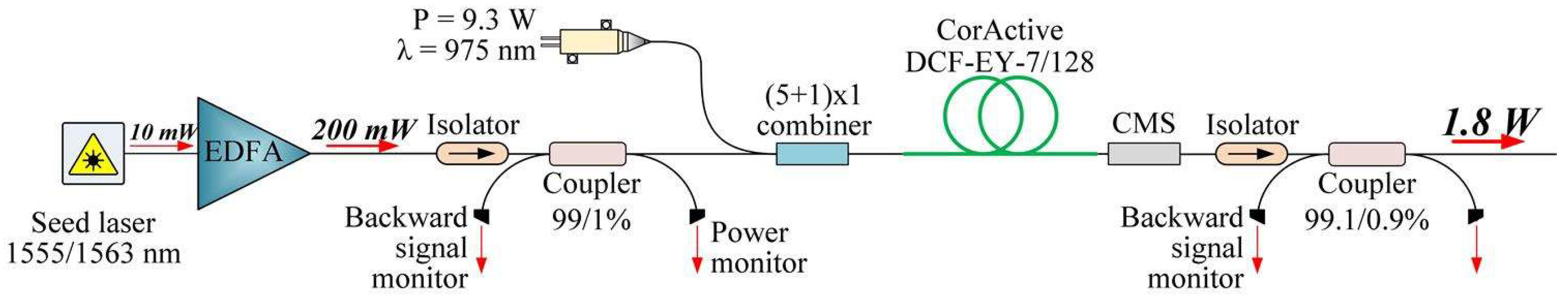
An experimental setup of the two first-MOPA-system stages is shown in Figure 1. A standard telecommunication distributed feedback (DFB) diode laser providing output power of 10 mW at 1555 nm and 1563 nm were used as a signal source. A pre-amplifier EDFA (Erbium Doped Fiber Amplifier) setup was based on an active 110-cm-long SM fiber doped with erbium ions (nLight LIEKKI Er 4/125) pumped in a backward direction (according to signal) by one SM diode laser operating at a working wavelength of 980 nm and output power of 600 mW. This stage amplified the signal up to 200 mW in the case of both the wavelengths (approximately 13 dB gain). The second stage -medium-power amplifier EYDFA (Erbium-Ytterbium Doped Fiber Amplifier) was based on a 5-meter-long Er/Yb co-doped SM-DC fiber (CorActive DCF-EY-7/128). Pumping of the active fiber was implemented in a forward direction, regarding the signal by a multimode laser diode operating at 975 nm with power of 9.3 W (JDSU 6398-L4i). The pump power was launched to the active fiber through a self-fabricated pump and signal power combiner in a configuration (5 + 1) × 1, which was recently presented in Reference [36]. At the input side, this combiner consisted of five pumping ports, i.e., multimode fibers with core/clad diameters of 105/125 µm (Numerical Aperture NA = 0.22) and one SM signal fiber with core/clad diameters of 9/80 µm (NA = 0.13). A passive SM-DC fiber with core/clad diameters of 9/125 µm (NA = 0.12/0.46) was used as the output of the combiner. The fabricated combiner provided a signal transmission efficiency at a level of 94% and a pump transmission efficiency close to 90%. In comparison, the same-class commercial pump and signal combiner (based on SM signal fibers at input and output) offered transmission efficiencies at a level of >90% for pump light and >85% for the signal [41]. The unabsorbed pump power in the active fiber was dissipated in a cladding-mode stripper (CMS). At the output of each stage of the amplifier, an optical isolator was placed and also fiber couplers (99/1% and 99.1/0.9%) were used in order to monitor output power at each stage as well as the backward stimulated Brillouin scattering (SBS) signal.
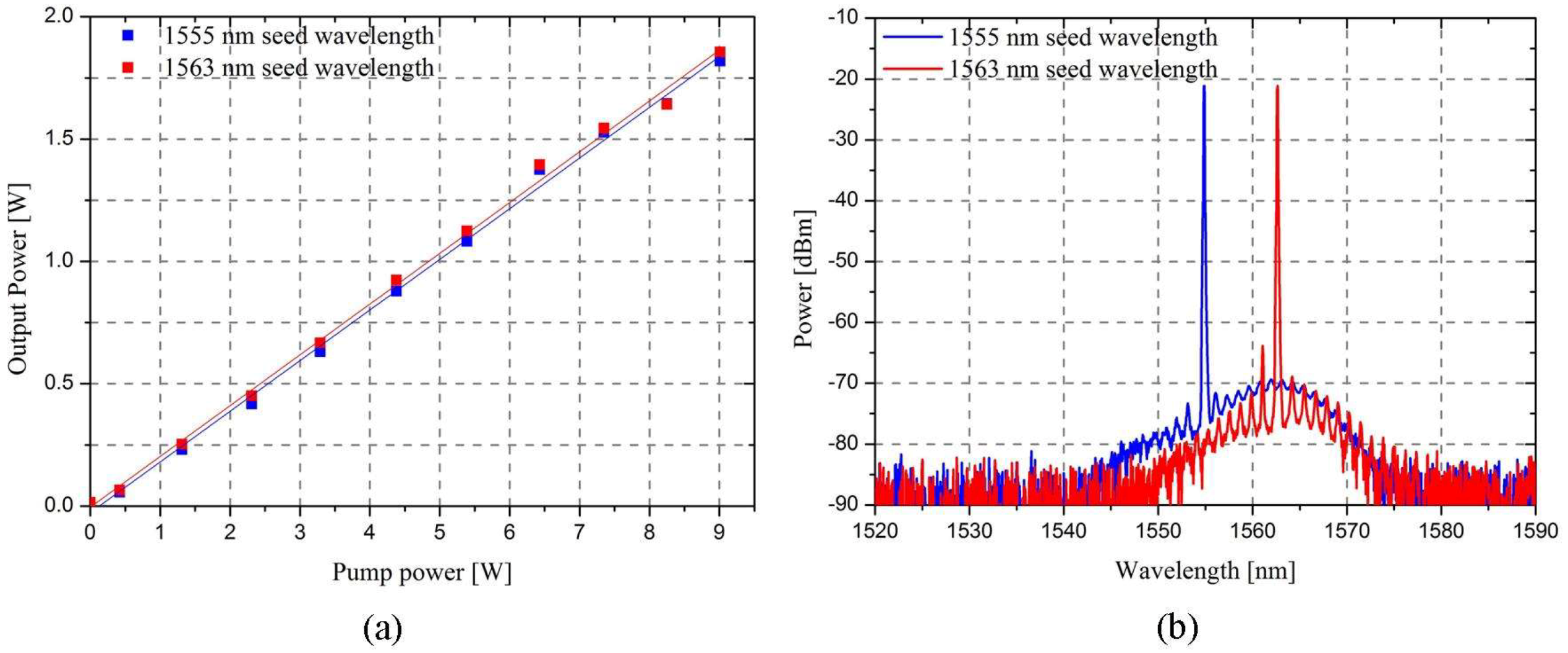
Characteristics of signal output power versus pump power in the second medium-power MOPA stage are presented in Figure 2a. At both the wavelengths of 1555 nm and 1563 nm, the power at a level of 1.8 W was achieved (the gain at a level of 9.5 dB) with the pump power of 9 W giving a slope efficiency of 20%.
Figure 2b shows the optical spectra at the seed wavelengths of 1555 nm and 1563 nm, which were recorded at the output of the second medium-power amplifier MOPA stage. The optical signal to the noise ratio (OSNR) at the maximum pump power of 9 W was at a level of 50 dB and was mainly determined by the seed laser noise. There was no sign of Yb-ASE occurrence at the output because of the relatively low level of the pump power.
2.2. Setup of Third-Stage Amplifier: High-Power EYDFA
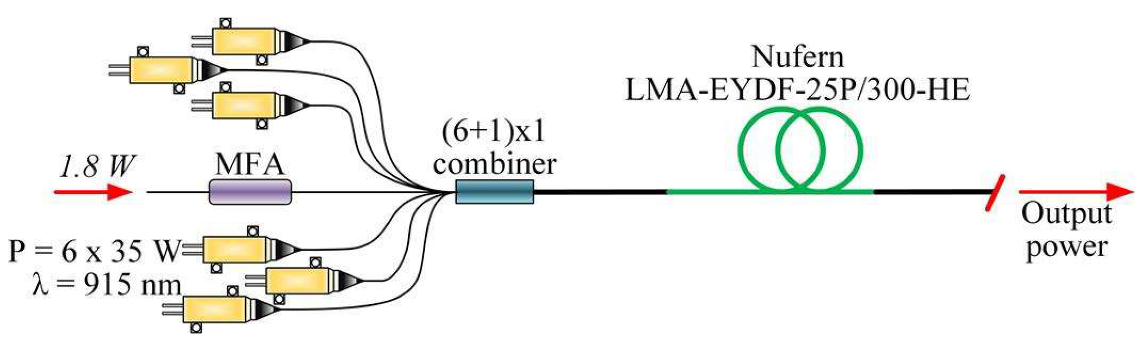
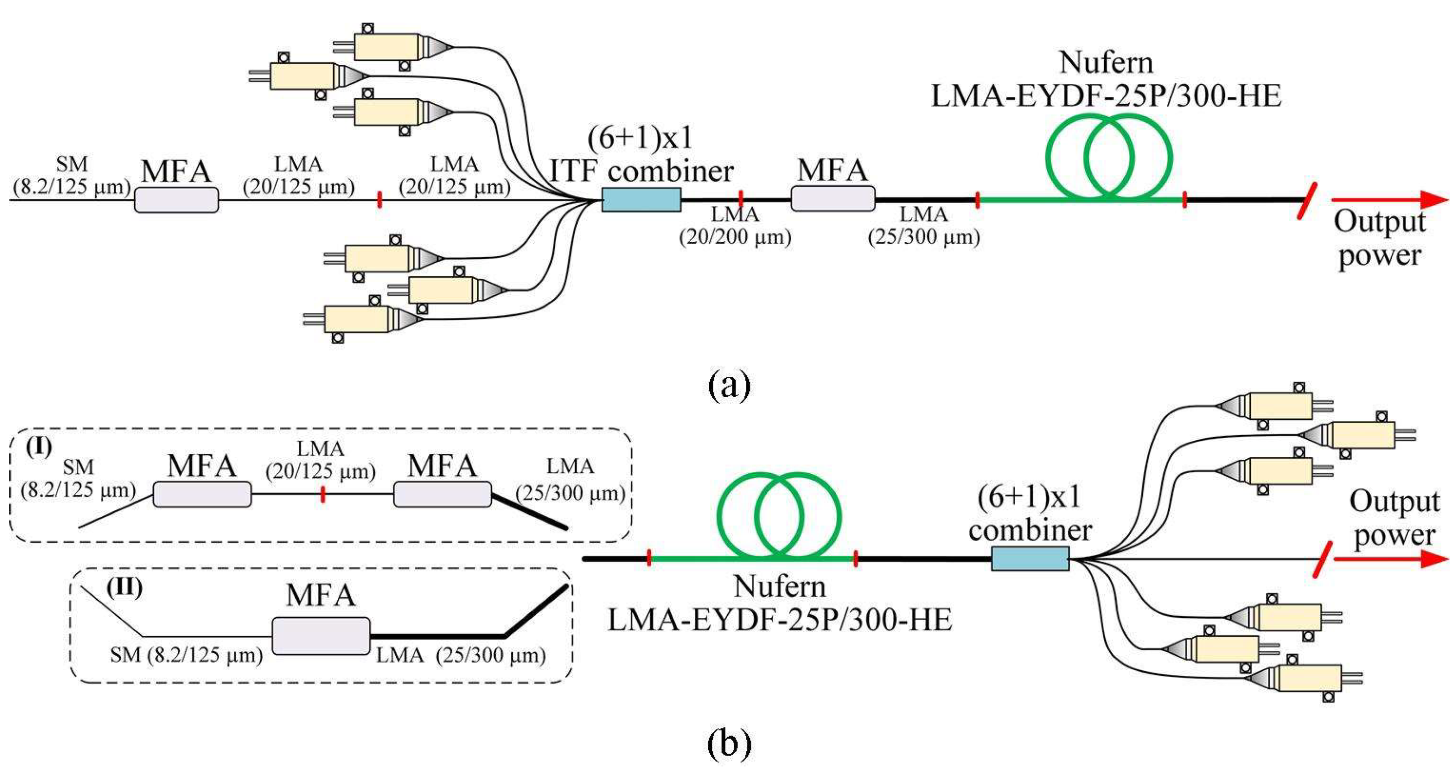
A setup of the third-stage MOPA, which was a high-power amplifier, is presented in Figure 3. It was based on a four-meter-long active Er/Yb co-doped LMA-type DC fiber with core/clad diameters of 25/300 µm (Nufern LMA-EYDF-25P/300-HE). The pump power from six multimode diode lasers (LIMO35-F100-DL915) with total available power of 210 W was launched into the active fiber in a forward direction using a self-fabricated pump and signal power combiner in a configuration (6 + 1) × 1, presented in our work [31]. This power combiner had six pump input ports—multimode fibers with core/clad diameters of 105/125 µm (NA = 0.22) and one signal LMA-type fiber with core/clad diameters of 20/130 µm. At the output of the combiner, an LMA-type DC passive fiber with core/clad diameters of 25/300 µm (NA = 0.09/0.46) was used, which was compatible with the active fiber used in the third MOPA stage. Our combiner provided a signal transmission efficiency at a level of 78% and a pump transmission efficiency at a very high level of approximately 98%. The output fiber from the second stage (SM, with core/clad diameters of 9/125 µm) was not compatible with the input signal fiber (with core/clad diameters of 20/125 µm) of the combiner, and the input fiber of the third MOPA stage. In order to overcome this issue, we used a self-fabricated MFA, which had a conventional SM fiber (SMF-28e) as an input port and an LMA-type fiber with diameters of 20/130 µm as an output port, which was the same as an input signal fiber in our power combiner. This component was characterized by a signal transmission efficiency at a level of 90%, so it is comparable with commercially available MFAs [42].
At the moment when we were working on this setup, we could use the (6 + 1) × 1 pump and signal power combiner (MMC06112571, ITF Technologies company) with 20/125 µm (core/clad diameters) input signal fiber and 20/200 µm (core/clad diameters) output DC fiber as a commercial alternative. This combiner was characterized with a pump transmission efficiency at a level of ˃93% and signal at a level of >89%. In this case, an MFA at the input was still needed not only to connect the SM fiber with 20/125 µm (core/clad diameters) fiber, but also to connect an output port from the combiner (with core/clad diameters of 20/200 µm) with our active fiber (with core/clad diameters of 25/300 µm), as shown in Figure 4a. Such a construction was used in our previous work [43]. This configuration of the MFA was not available in commercial offers; thus, we fabricated it by tapering the LMA fiber with core/clad diameters of 25/300 µm and splicing it with the output port of the ITF Technologies combiner (with core/clad diameters of 20/200 µm). The developed MFA was characterized with pump and signal transmission efficiencies at a level of approximately 92%.
If we used an ITF (6 + 1) × 1 combiner with transmission loss at a level of approximately 0.5 dB and a self-fabricated MFA with a transmission loss of 0.35 dB (connecting 20/125 µm combiner output DC fiber with 25/300 µm active fiber) in the third amplifier construction, the total signal transmission loss through those two components would be at a level of 0.85 dB. However, although both of them were propagating pump power, the combiner pump transmission losses of the combiner and the self-fabricated MFA was approximately 0.32 dB and approximately 0.35 dB, respectively, giving the pump power transmission loss of 0.67 dB in total. Using our self-fabricated (6 + 1) × 1 power combiner guaranteed a very low pump transmission loss at a level of only 0.09 dB, which was much lower than that in the case of commercial combiners. The signal transmission loss was at a level of 1.08 dB. Even though the signal loss is larger than that in the case of an ITF combiner, we had to also take into account the number of splices:
- 1st additional splice as a combiner with MFA,
- 2nd additional splice inside the MFA combined with an active fiber.
Because those are LMA-type fibers, they are extremely sensitive to angular misalignments. For example, a 0.5° angular misalignment on a fiber with mode field diameter MFD = 6 µm resulted with a small transmission loss of 0.06 dB, while in the case of MFD = 20 µm, the loss increased to almost 0.7 dB [35]. Thus, it is profitable to limit the number of splices in order to avoid any additional losses. In addition, such a loss on a splice means leaking of a power, and since we are dealing with high powers, those leaks could lead to point overheating and finally damage the fibers and the setup. Taking all above into account, we chose one component with a higher signal-power transmission loss of only 0.23 dB, but with a lower pump-power transmission loss of 0.58 dB, under which circumstance, the number of splice was reduced from 2 to 1. We chose the forward-direction pumping scheme because of two reasons. First reason is that if we chose the backward-direction pumping scheme, additional MFAs would be needed to connect output fiber (20/125 µm) with both the input MFA and an active fiber (25/300 µm) (Figure 4b(I)). On the other hand, two MFAs could be replaced with one MFA connecting an SM fiber (8.2/125 µm) with an LMA fiber (25/300 µm) (Figure 4b(II)). However, large difference between mode field diameter could cause large losses. The second reason of choosing the forward-pumping scheme was the safe operation of the system. The backward-pumping scheme was quite dangerous, because in the case of a small change of the pump diode temperature, its operating wavelength could shift, leading to a decrease of the absorption in the active fiber. The unabsorbed pump power could reach the signal source, or in the case of the bidirectional pumping scheme, it could reach the pump diodes used for the forward pumping, resulting in damaging of the whole setup.
The real level of the pump power which was reaching the active fiber was smaller than that provided by a pumping laser. Significant laser power was guided in cladding modes of the output fiber of the pumping laser. To secure safe operation conditions, a cladding-mode striper was placed on each splice connecting the laser pigtail (100/140 µm) and the standard MM fiber (105/125 µm) of the power combiner. A measured waste of the pump power was approximately 30% of the total pumping power, decreasing it to a level of 147 W. If we also took into account the small pump power attenuation by the fabricated combiner, the pump power reaching the active fiber was at a level of approximately 144 W. The output of the third stage was terminated with a short piece of passive LMA fiber, which was cut at an angle of 4° (larger than a critical angle corresponding to the NA of the used LMA fiber) in order to avoid back-reflections from the fiber end and ensure the safe operation of the system.
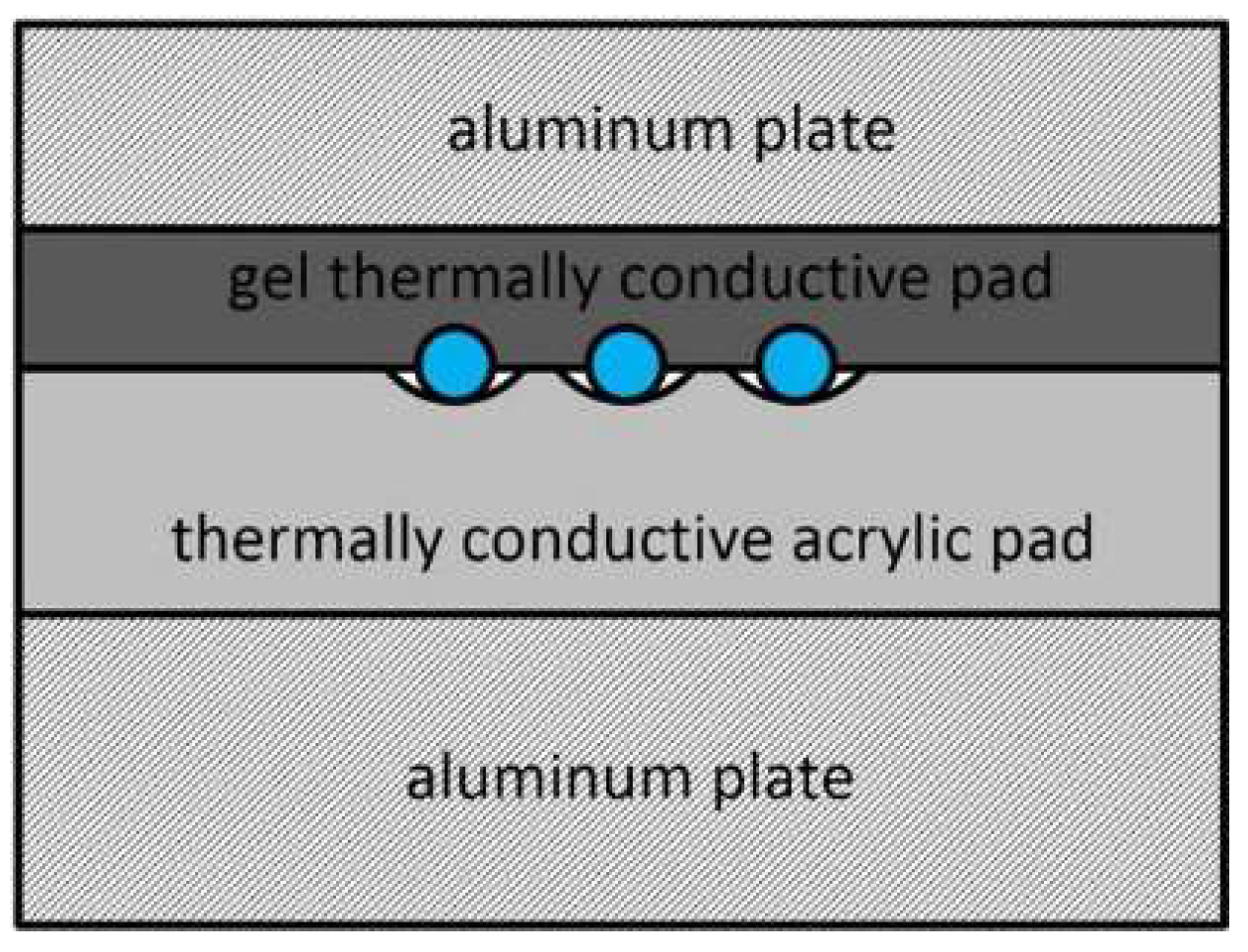
Since the setup was designed for pure CW operation, a special care must be taken with respect to thermal issues in the system. Most of the dissipated optical power was converted into heat in the active fiber. With respect to a relatively small volume of the active fiber, the proper and effective cooling method should be used in the third high-power stage of our MOPA system. With only air-based cooling, the pumping end of active fiber reached high temperature very rapidly, resulting in damage to the cladding and thereby the whole system. Especially the pumping end of an active fiber should be cooled efficiently, since almost half of the pumping power was dissipated in its first meter, because of its high pump absorption. At first, the active fiber was spliced to exactly match passive DC fiber buffer from both the sides. Then the active fiber was placed in a thermal conductive medium. We decided to use commercially-available thermally-conductive pads dedicated to electronics components, which were sandwiched between two aluminum plates in a way shown in Figure 5.
The active fiber and passive buffers were placed circularly on an acrylic thermal pad and covered by an aluminum plate covered by a gel thermal pad. In this way, a perfect thermal contact was obtained, and no excessive mechanical stress was induced into the active fiber.
3. Experimental Results
A graph showing measured output power of the three-stage MOPA setup for operation on both the wavelengths (1555 and 1563 nm) versus pump power of the third high-power amplifier stage is shown in Figure 6. The maximum achieved output power was approximately 44 W at the pump power of 144 W at the wavelength of 915 nm. The achieved slope efficiency was at a level of approximately 33% in the case of the MOPA operating at the wavelengths of 1555 nm and 1563 nm. As can be seen, there was no decrease in the slope efficiency even at highest pumping power, which led us to assume that the output power was currently limited only by the available pump power. In both the cases, the input signal of 1.8 W from the second stage was amplified with a gain of approximately 13.9 dB. Taking into account that we used 10 mW seed laser, we characterized the presented MOPA system with a total gain at a level of approximately 36.4 dB.
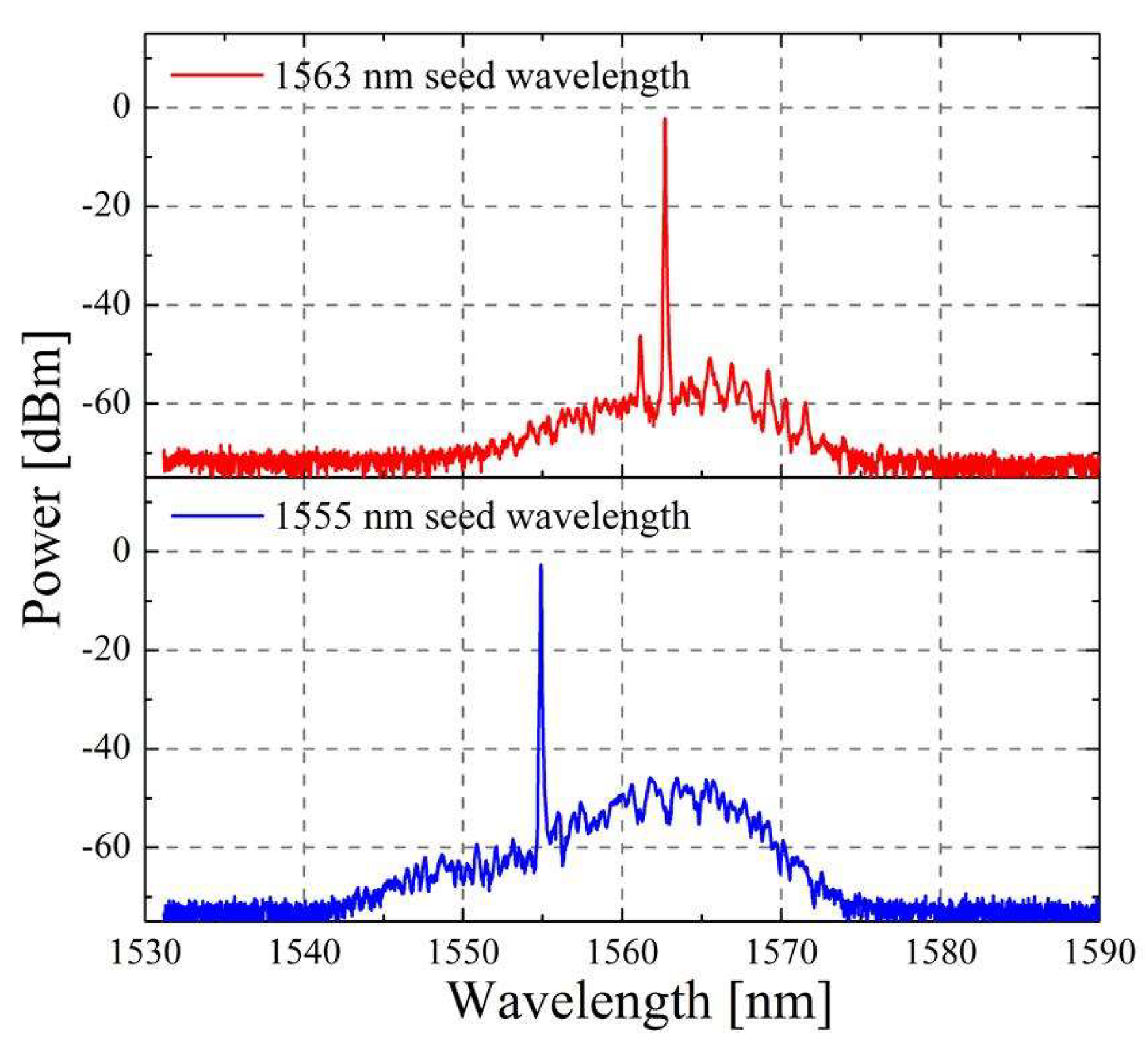
Figure 7 shows the recorded spectra of the amplified signal at the output of the three-stage MOPA setup. It was characterized by a very low amplified spontaneous emission (ASE) level of the output signal at the wavelengths of 1555 nm and 1563 nm. The registered OSNR was at a level over 40 dB in both the cases. In addition, during the measurement, we were controlling Yb-ASE emission in the spectral region of 1 µm, and it was at a low level below 0.6 W, and we did not observe any spontaneous lasing.
4. Conclusions
In conclusion, we have demonstrated an all-fiber high-power CW-operating MOPA system, in which we have used self-fabricated passive fiber components: pump and signal power combiners in the configuration (5 + 1) × 1 using SM signal fibers and in the configuration (6 + 1) × 1 using LMA-type signal fiber, and also an MFA for connection of the SM fiber (8.2/125 µm) with the LMA-type fiber (20/130 µm). The presented MOPA system consisted of three stages: pre-amplifier (EDFA based on erbium-doped active SM fibers), medium-power amplifier (EYDFA based Er/Yb co-doped active SM-DC fiber) and high-power amplifier (EYDFA based on Er/Yb co-doped active LMA-type DC fiber). The maximum achieved CW power was approximately 44 W at the wavelengths of 1555 nm and 1563 nm in the presence of the pumping at the power of 144 W and the wavelength of 915 nm. The presented MOPA setup confirmed functionality of our self-fabricated high-power passive fiber components and their capability for stable operation in high-power radiation regimes. Further research on the high-power passive components will lead to improvement of their transmission parameters, leading to improved efficiency of MOPA systems.
Author Contributions
P.K. and D.S. designed the experimental MOPA system; D.S. designed and fabricated high-power passive fiber components; P.K. and D.S. performed the MOPA system demonstration and characterization; P.K., D.S. and K.M.A. analyzed the data; P.K. and D.S. wrote the manuscript.
Acknowledgments
D.S. and K.M.A acknowledge support from the National Science Centre (NCN), Poland under the project “Pump and signal power combiner with improved signal transmission efficiency” (decision No. UMO-2015/19/N/ST7/01511); P.K., D.S. and K.M.A. acknowledge support from the Wroclaw Research Centre EIT+ under the project ‘‘The Application of Nanotechnology in Advanced Materials”—NanoMat (POIG.01.01.02-02-002/08-00) financed by the European Regional Development Fund (Innovative Economy Operational Programme, 1.1.2); P.K. and K.M.A. acknowledge support from the statutory funds of WrUST (grant No. 0401/0137/16); D.S. acknowledge partial support from the action COST MP1401 “Advanced Fibre Laser and Coherent Source as tools for Society, Manufacturing and Lifescience” (2014–2018).
Conflicts of Interest
The authors declare no conflicts of interest.
References
- Philippov, V.; Codemard, C.; Jeong, Y.; Alegria, C.; Sahu, J.K.; Nilsson, J.; Pearson, G.N. High-energy in-fiber pulse amplification for coherent lidar applications. Opt. Lett. 2004, 29, 2590–2592. [Google Scholar] [CrossRef] [PubMed]
- Codemard, C.; Farrell, C.; Dupriez, P.; Philippov, V.; Sahu, J.K.; Nilsson, J. Millijoule, high-peak power, narrow-linewidth, subhundred nanosecond pulsed fibre Master-Oscillator Power- Amplifier ar 1.55 μm. C. R. Phys. 2006, 7, 170–176. [Google Scholar] [CrossRef]
- Dolfi-Bouteyre, A.; Canat, G.; Valla, M.; Augere, B.; Besson, C.; Goular, D.; Lombard, L.; Cariou, J.P.; Durecu, A.; Fleury, D.; et al. Pulsed 1.5-μm LIDAR for axial aircraft wake vortex detection based on highbrightness large-core fiber amplifier. IEEE J. Sel. Top. Quantum Electron. 2009, 15, 441–450. [Google Scholar] [CrossRef]
- Wagener, J.L.; DiGiovanni, D.J.; Wysocki, P.F.; Digonnet, M.J.F.; Shaw, H.J. Effects of concentration and clusters in erbium-doped fiber lasers. Opt. Lett. 1993, 18, 2014–2016. [Google Scholar] [CrossRef] [PubMed]
- Guzman-Chavez, D.; Barmenkov, Y.O.; Kir’yanov, A.V. Spectral dependence of the excited-state absorption of erbium in silica fiber within the 1.48–1.59 m range. Appl. Phys. Lett. 2008, 92, 191111. [Google Scholar] [CrossRef]
- Delevaque, E.; Georges, T.; Monerie, M.; Lamouler, P.; Bayon, J.-F. Modeling of pair-induced quenching in erbium-doped silicate fibers. IEEE Photon. Technol. Lett. 1993, 5, 73–75. [Google Scholar] [CrossRef]
- Kuhn, V.; Kracht, D.; Neumann, J.; Weßels, P. 67 W of output power from an Yb-free Er-doped fiber amplifier cladding pumped at 976 nm. IEEE Photon. Technol. Lett. 2011, 23, 432–434. [Google Scholar] [CrossRef]
- Zhang, J.; Fromzel, V.; Dubinskii, M. Resonantly cladding-pumped Yb-free Er-doped LMA fiber laser with record high power and efficiency. Opt. Express 2011, 19, 5574–5578. [Google Scholar] [CrossRef] [PubMed]
- Dubinskii, M.; Zhang, J.; Ter-Mikirtychev, V. Highly scalable, resonantly cladding-pumped, Er-doped fiber laser with record efficiency. Opt. Lett. 2009, 34, 1507–1509. [Google Scholar] [CrossRef] [PubMed]
- Lim, E.L.; Alam, S.U.; Richardson, D.J. High-energy, in-band pumped erbium doped fiber amplifiers. Opt. Express 2012, 20, 18803–18818. [Google Scholar] [CrossRef] [PubMed]
- Yahel, E.; Hardy, A. Efficiency optimization of high-power, Er3+-Yb3+-codoped fiber amplifiers for wavelength-division-multiplexing applications. J. Opt. Soc. Am. B 2003, 20, 1189–1197. [Google Scholar] [CrossRef]
- Jeong, Y.; Yoo, S.; Codemard, C.A.; Nilsson, J.; Sahu, J.K.; Payne, D.N.; Horley, R.; Turner, P.W.; Hickey, L.; Harker, A.; et al. Erbium:ytterbium codoped large-core fiber laser with 297-W continuous-wave output power. IEEE J. Sel. Top. Quantum 2007, 13, 573–579. [Google Scholar] [CrossRef]
- Jeong, Y.; Sahu, J.K.; Soh, D.B.S.; Codemard, C.A.; Nilsson, J. High-power tunable single-frequency single-mode erbium:ytterbium codoped large-core fiber master-oscillator power amplifier source. Opt. Lett. 2005, 30, 2997–2999. [Google Scholar] [CrossRef] [PubMed]
- De Varona, O.; Fittkau, W.; Booker, P.; Theeg, T.; Steinke, M.; Kracht, D.; Neumann, J.; Wessels, P. Single-frequency fiber amplifier at 1.5 µm with 100 W in the linearly-polarized TEM00 mode for next-generation gravitational wave detectors. Opt. Express 2017, 25, 24880–24892. [Google Scholar] [CrossRef] [PubMed]
- Gonthier, F.; Martineau, L.; Azami, N.; Faucher, M.; Seguin, F.; Stryckman, D.; Villeneuve, A. High-power all-fibre components: The missing link for high-power fibre lasers. Proc. SPIE 2004, 5335. [Google Scholar] [CrossRef]
- Richardson, D.J.; Nilsson, J.; Clarkson, W.A. High power fiber lasers: Current status and future perspectives [Invited]. J. Opt. Soc. Am. B 2010, 27, B63–B92. [Google Scholar] [CrossRef]
- Shi, W.; Fang, Q.; Zhu, X.; Norwood, R.A.; Peyghambarian, N. Fibre lasers and their applications [Invited]. Appl. Opt. 2014, 53, 6554–6568. [Google Scholar] [CrossRef] [PubMed]
- Gapontsev, V.P.; Samartsev, L.E. High-power fiber laser. OSA Proc. Adv. Solid State Lasers 1990, 6. [Google Scholar] [CrossRef]
- Gapontsev, V.P.; Samartsev, I. Coupling Arrangement between a Multi-Mode Light Source and an Optical Fiber through an Intermediate Optical Fiber Length. U.S. Patent 5,999,673, 7 December 1999. Available online: https://patentimages.storage.googleapis.com/b3/5d/29/390f769901abd7/US5999673.pdf (accessed on 25 May 2018).
- DiGiovanni, D.J.; Stentz, A.J. Tapered Fiber Bundles for Coupling Light Into and Out of Cladding-Pumped Fiber Devices. U.S. Patent 5,864,644, 26 January 1999. Available online: https://patentimages.storage.googleapis.com/a9/94/bb/7cd3fbe58cd27c/US5864644.pdf (accessed on 25 May 2018).
- Jauregui, C.; Bohme, S.; Wenetiadis, G.; Limpert, J.; Tünnermann, A. Side-pump combiner for all-fiber monolithic fiber lasers and amplifiers. J. Opt. Soc. Am. B 2010, 27, 1011–1015. [Google Scholar] [CrossRef]
- Braglia, A.; Califano, A.; Liu, Y.; Perrone, G. Architectures and components for high power CW fiber lasers. Int. J. Mod. Phys. B 2014, 28, 1442001. [Google Scholar] [CrossRef]
- Yusim, A.; Barsalou, J.; Gapontsev, D.; Platonov, N.S.; Shkurikhin, O.; Gapontsev, V.P.; Barannikov, Y.A.; Shcherbina, F.V. 100 watt single-mode CW linearly polarized all-fiber format 1.56 μm laser with suppression of parasitic lasing effects. Proc. SPIE 2005, 5709. [Google Scholar] [CrossRef]
- Bai, X.; Sheng, Q.; Zhang, H.; Fu, S.; Shi, W.; Yao, J. High-Power All-Fiber Single-Frequency Erbium–Ytterbium Co-Doped Fiber Master Oscillator Power Amplifier. IEEE Photon. J. 2015, 7, 1–6. [Google Scholar] [CrossRef]
- Kotov, L.V.; Likhachev, M.E.; Bubnov, M.M.; Medvedkov, O.I.; Yashkov, M.V.; Guryanov, A.N.; Février, S.; Lhermite, J.; Cormier, E. Yb-free Er-doped all-fiber amplifier cladding-pumped at 976 nm with output power in excess of 100 W. Proc. SPIE 2014, 8961. [Google Scholar] [CrossRef]
- Noordegraaf, D.; Maack, M.D.; Skovgaard, P.M.W.; Johansen, J.; Becker, F.; Belke, S.; Blomqvist, M.; Laegsgaard, J. All-fiber 7x1 signal combiner for incoherent laser beam combining. Proc. SPIE Int. Soc. Opt. Eng. 2011, 7914. [Google Scholar] [CrossRef] [Green Version]
- Kosterin, A.; Temyanko, V.; Fallahi, M.; Mansuripur, M. Tapered fiber bundles for high power applications. In Proceedings of the Technical Digest, Optical Fiber Communication Conference, Anaheim, CA, USA, 6–11 March 2005. [Google Scholar]
- Braglia, A.; Olivero, M.; Neri, A.; Perrone, G. Fabrication of pump combiners for high power fibre lasers. Proc. SPIE 2011, 7914. [Google Scholar] [CrossRef]
- Zhao, K.; Chang, X.; Chen, Z.; Wang, Z.; Jiang, H. Fabrication of high-efficiency pump and signal combiner based on a thermally expanded core technique. Opt. Laser Technol. 2015, 75, 1–5. [Google Scholar] [CrossRef]
- Koška, P.; Baravets, Y.; Peterka, P.; Bohata, J.; Pisarik, M. Mode_field adapter for tapered_fibre_bundle signal and pump combiners. Appl. Opt. 2015, 54, 751–756. [Google Scholar] [CrossRef] [PubMed]
- Sliwinska, D.; Kaczmarek, P.; Abramski, K.M. Tapered fiber bundle couplers for high-power fiber amplifiers. Proc. SPIE 2014, 9441. [Google Scholar] [CrossRef]
- Stachowiak, D.; Kaczmarek, P.; Abramski, K.M. High-power pump combiners for Tm-doped fibre lasers. Opto-Electron. Rev. 2015, 23, 259–264. [Google Scholar] [CrossRef]
- Sévigny, B.; Poirier, P.; Faucher, M. Pump combiner loss as a function of input numerical aperture power distribution. Proc. SPIE 2009, 7195. [Google Scholar] [CrossRef]
- Wiley, R.; Clark, B. High-power, fused assemblies enabled by advances in fiber processing technologies. Proc. SPIE 2011, 7914. [Google Scholar] [CrossRef]
- Wang, B.; Mies, E. Review of fabrication techniques for fused fibre components for fibre lasers. Proc. SPIE 2009, 7195. [Google Scholar] [CrossRef]
- Stachowiak, D.; Kaczmarek, P.; Abramski, K.M. (5 + 1) × 1 pump and signal power combiner with 9/80 µm feed-through signal fiber. Opt. Laser Technol. 2017, 93, 33–40. [Google Scholar] [CrossRef]
- Bansal, L.; Rosalesgarcia, A.; Supradeepa, V.R.; Taunay, T.; Headley, C. Efficient pump combiner’s for fiber lasers and amplifiers. Proc. SPIE 2016, 9728. [Google Scholar] [CrossRef]
- Liao, L.; Liu, P.; Wang, X.Y.B.; Dai, N.L.; Li, J.Y.; He, B.; Zhou, J. The crucial fiber components and gain fiber for high power ytterbium-doped fiber laser. Proc. SPIE 2015, 9621. [Google Scholar] [CrossRef]
- Zheng, J.; Zhao, W.; Zhao, B.; Li, Z.; Chang, C.; Li, G.; Gao, Q.; Ju, P.; Gao, W.; She, S.; et al. High pumping-power fiber combiner for double-cladding fiber lasers and amplifiers. Opt. Eng. 2018, 57, 036105. [Google Scholar] [CrossRef]
- Zou, S.; Chen, H.; Yu, H.; Sun, J.; Zhao, P.; Lin, X. High-efficiency (6 + 1) × 1 pump–signal combiner based on low-deformation and high-precision alignment fabrication. Appl. Phys. B 2017, 123. [Google Scholar] [CrossRef]
- Gooch & Housego, 6 + 1 × 1 MM Power Combiner with Signal Feedthrough. Available online: https://goochandhousego.com/wp-content/uploads/2018/02/GH-DS-FO-TFB-61x1-Power-Combiner.pdf (accessed on 19 April 2018).
- Lightcomm Technology. Available online: http://www.lightcomm.com/product/view/typeid/130/id/72.html (accessed on 19 April 2018).
- Sobon, G.; Kaczmarek, P.R.; Sliwinska, D.; Sotor, J.; Abramski, K.M. High-Power Fiber-Based Femtosecond CPA System at 1560 nm. IEEE J. Sel. Top. Quantum Electron. 2014, 20, 492–496. [Google Scholar] [CrossRef]
Figure 1.
Experimental setup of two first-MOPA-system stages—preamplifier EDFA (Erbium Doped Fiber Amplifier), and amplifier EYDFA (Erbium-Ytterbium Doped Fiber Amplifier).
Figure 1.
Experimental setup of two first-MOPA-system stages—preamplifier EDFA (Erbium Doped Fiber Amplifier), and amplifier EYDFA (Erbium-Ytterbium Doped Fiber Amplifier).

Figure 2.
Characteristics of signal output power versus pump power (a) and optical spectra at the seed wavelength of 1555 nm and 1563 nm (b) recorded at the output of the second medium-power amplifier MOPA stage.
Figure 2.
Characteristics of signal output power versus pump power (a) and optical spectra at the seed wavelength of 1555 nm and 1563 nm (b) recorded at the output of the second medium-power amplifier MOPA stage.

Figure 3.
Experimental setup of the third MOPA stage—high-power amplifier EYDFA.

Figure 4.
Alterative solution of the third MOPA stage construction: with commercial pump and signal power combiner (a) and with a backward-pumping scheme (b).
Figure 4.
Alterative solution of the third MOPA stage construction: with commercial pump and signal power combiner (a) and with a backward-pumping scheme (b).

Figure 5.
Cooling scheme of the active fiber of the third MOPA system stage.

Figure 6.
Characteristics of signal output power versus pump power in the case of the MOPA operating at 1555 nm and 1563 nm.
Figure 6.
Characteristics of signal output power versus pump power in the case of the MOPA operating at 1555 nm and 1563 nm.
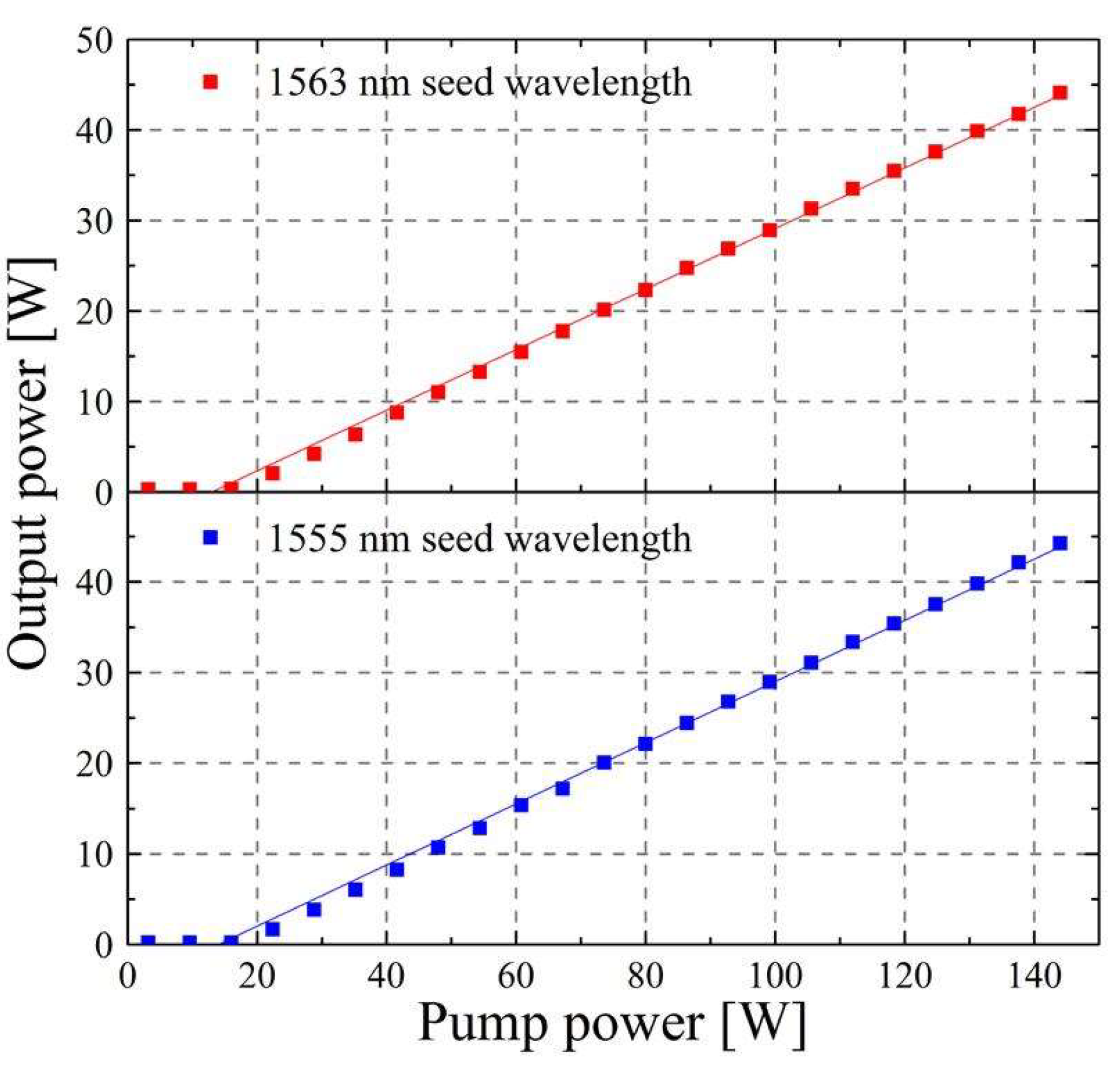
Figure 7.
Optical spectra of the output signal at the wavelengths of 1555 nm and 1563 nm.


Table 1.
Most important parameters of mentioned MOPA (master oscillator power amplifier)/laser systems.
Table 1.
Most important parameters of mentioned MOPA (master oscillator power amplifier)/laser systems.
| Ref. | Gain Medium | Output Power | Pump Power | Slope Efficiency | System Type |
|---|---|---|---|---|---|
| Construction with bulk optics | |||||
| [7] | LMA Er3+ | 67 W @ 1570 nm | 225 W @ 976 nm | 30% | MOPA |
| [12] | DC LMA Er3+/Yb3+ | 297 W @ 1567 nm | 1.2 kW @ 975 nm | 40% → 19% | Laser |
| [13] | DC LMA Er3+/Yb3+ | 151 W @ 1563 nm | 470 W @ 975 nm | 35% → 29% | MOPA |
| All-fiber amplifier construction + free-space seed signal coupling | |||||
| [14] | DC LMA Er3+/Yb3+ | 110 W @ 1556 nm | 250 W @ 940 nm | 46% | MOPA |
| All-fiber construction | |||||
| [23] | PM DC LMA Er3+/Yb3+ | 100 W @ 1566.5 nm | 360 W @ 965 nm | 29% | MOPA |
| [24] | PM DC LMA Er3+/Yb3+ | 56.4 W @ 1550 nm | 150 W @ 976 nm | 37% | MOPA |
| [25] | DC LMA Er3+ | 103 W @ 1585 nm | 275 W @ 976 nm | 37% | MOPA |
© 2018 by the authors. Licensee MDPI, Basel, Switzerland. This article is an open access article distributed under the terms and conditions of the Creative Commons Attribution (CC BY) license (http://creativecommons.org/licenses/by/4.0/).
Share and Cite
MDPI and ACS Style
Kaczmarek, P.; Stachowiak, D.; Abramski, K.M. 40 W All-Fiber Er/Yb MOPA System Using Self-Fabricated High-Power Passive Fiber Components. Appl. Sci. 2018, 8, 869. https://doi.org/10.3390/app8060869
AMA Style
Kaczmarek P, Stachowiak D, Abramski KM. 40 W All-Fiber Er/Yb MOPA System Using Self-Fabricated High-Power Passive Fiber Components. Applied Sciences. 2018; 8(6):869. https://doi.org/10.3390/app8060869
Chicago/Turabian StyleKaczmarek, Pawel, Dorota Stachowiak, and Krzysztof M. Abramski. 2018. "40 W All-Fiber Er/Yb MOPA System Using Self-Fabricated High-Power Passive Fiber Components" Applied Sciences 8, no. 6: 869. https://doi.org/10.3390/app8060869
Note that from the first issue of 2016, this journal uses article numbers instead of page numbers. See further details here.