Design of Demonstration-Driven Assembling Manipulator


Abstract
:
1. Introduction
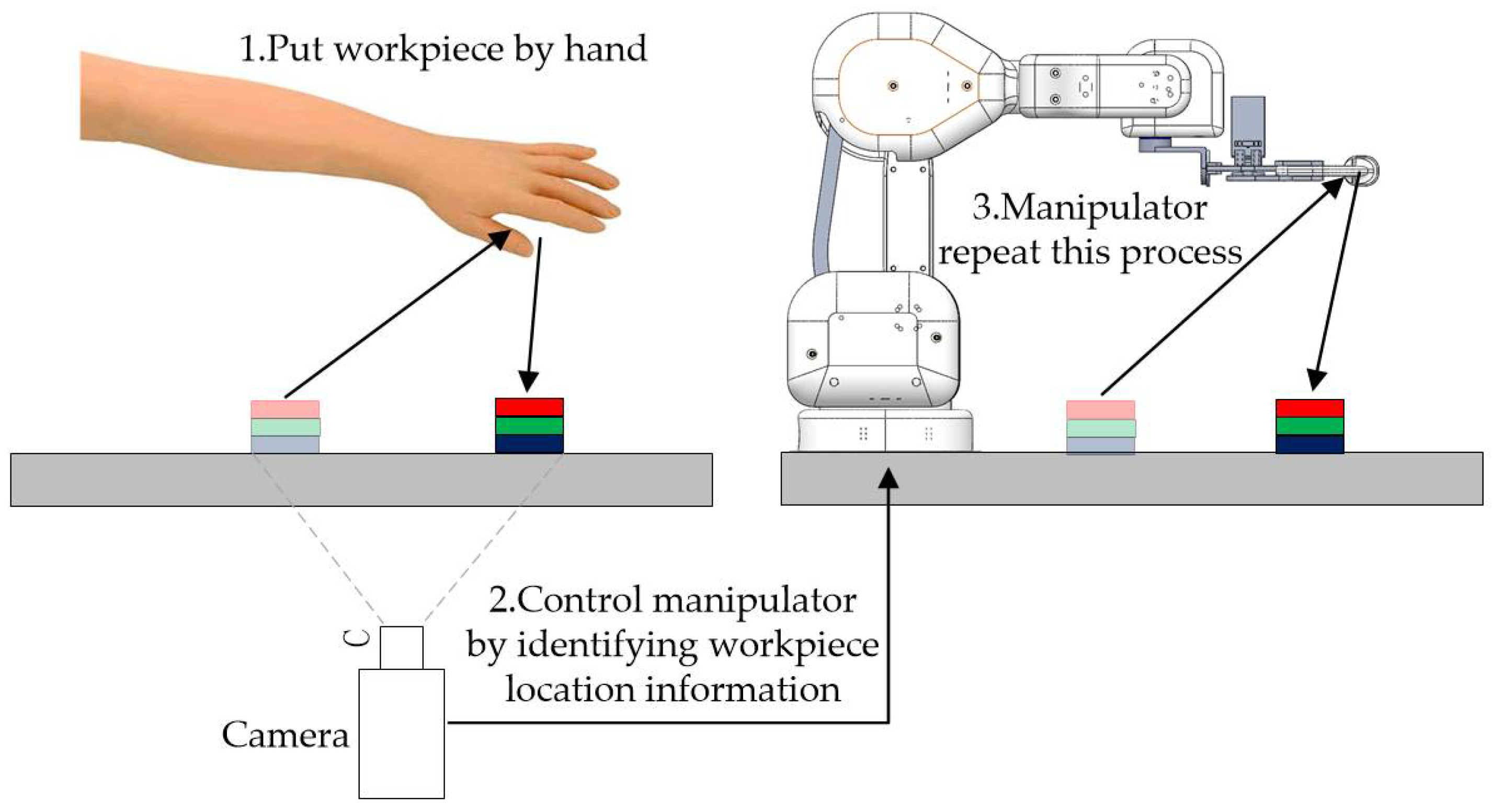
2. Methods
3. Implementation
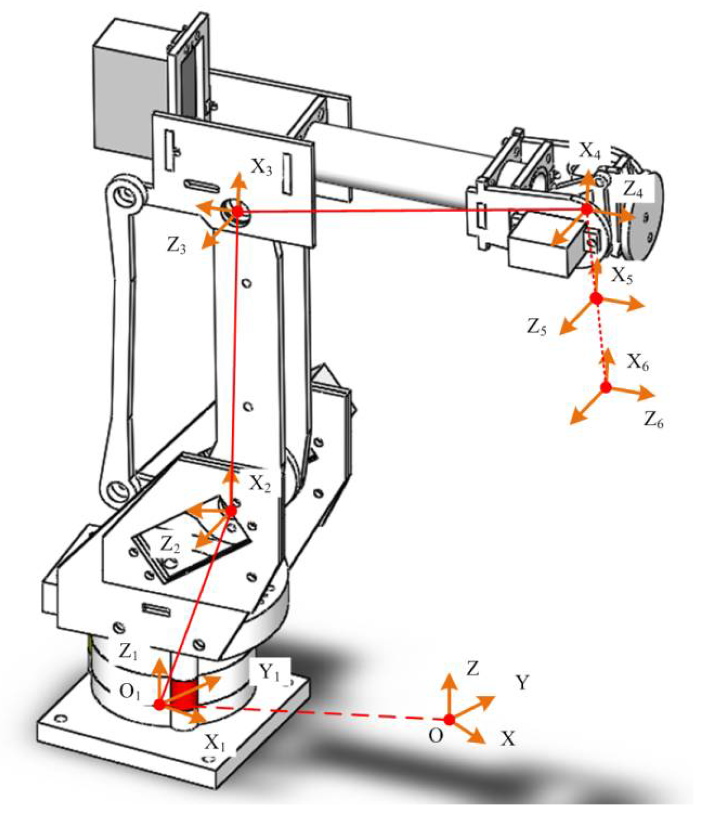
3.1. Kinematics Modeling of Manipulator
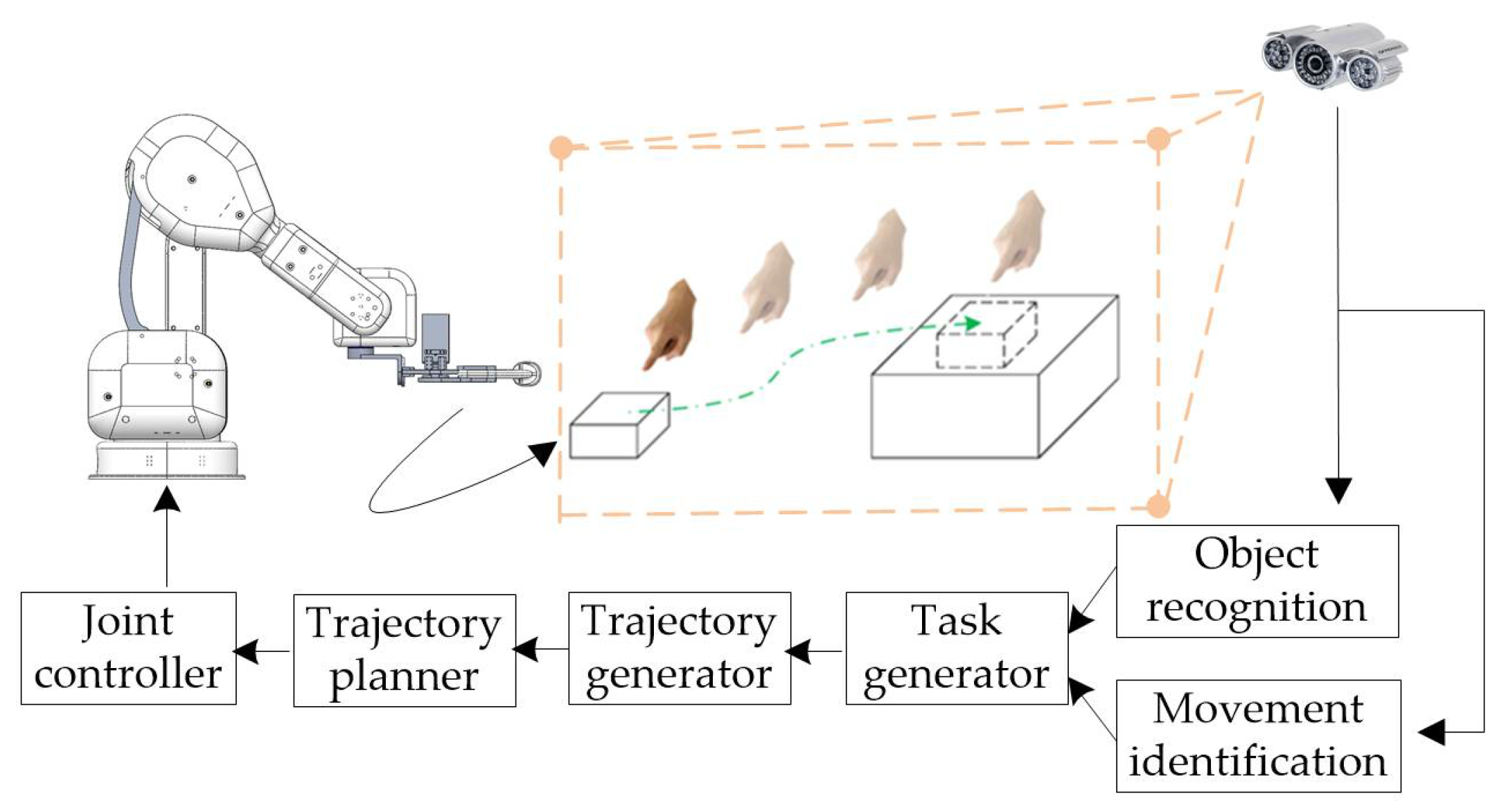
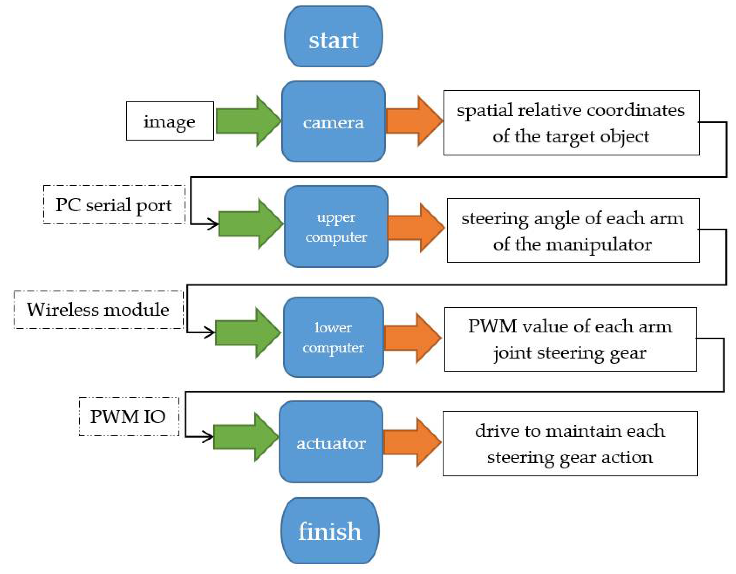
3.2. Automatic Control of the Manipulator
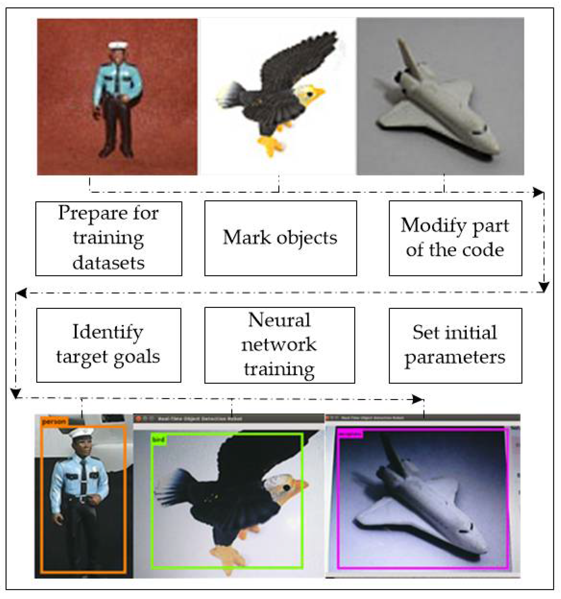
3.3. Object Recognition with YOLO
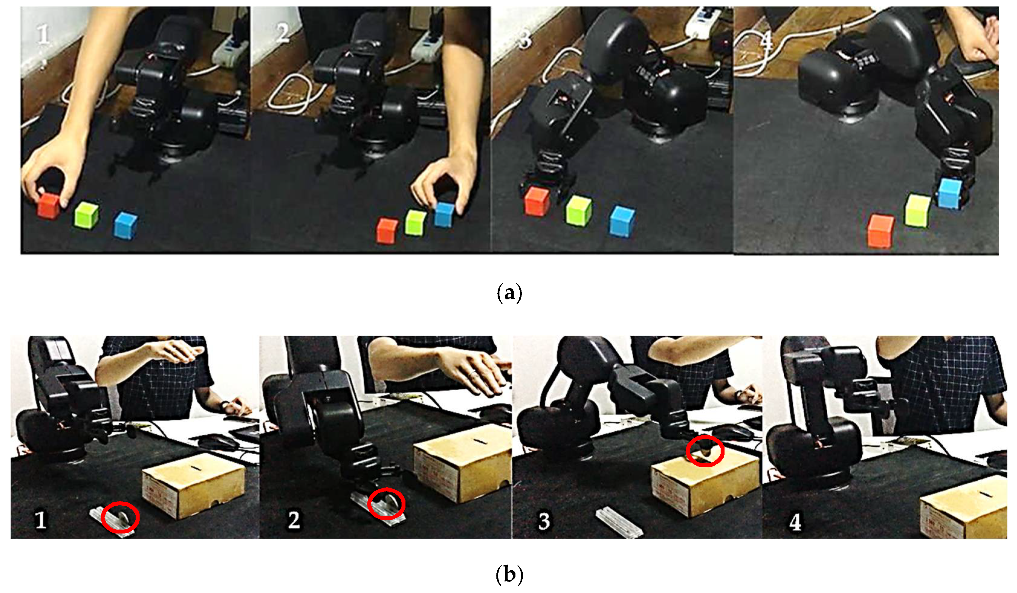
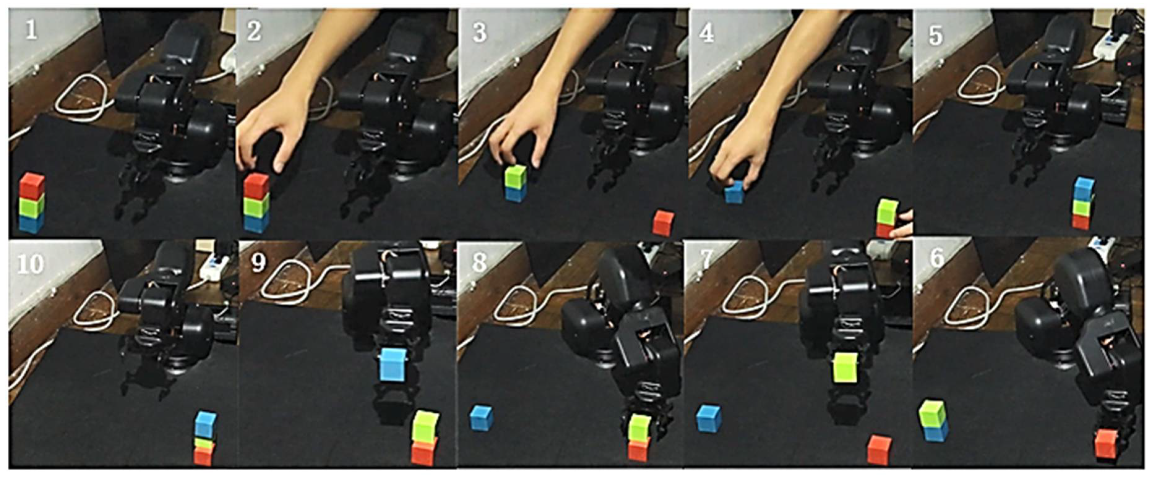
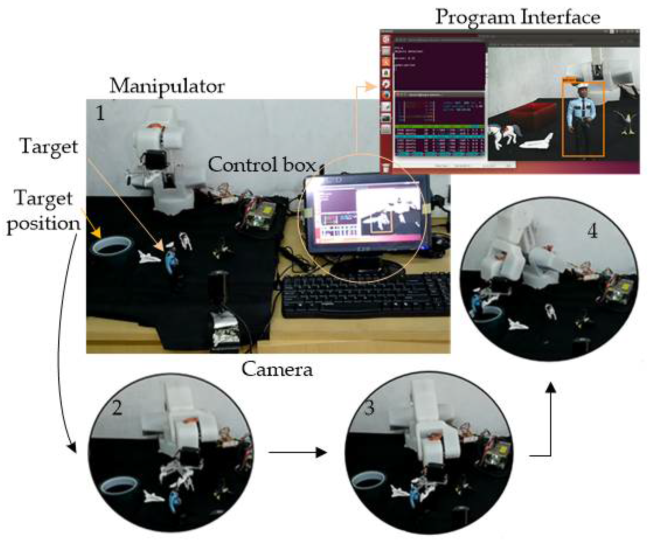
4. Experimental
5. Discussion and Conclusions
Author Contributions
Acknowledgments
Conflicts of Interest
References
- Brogårdh, T. Present and future robot control development—An industrial perspective. Annu. Rev. Control 2007, 31, 69–79. [Google Scholar] [CrossRef]
- Luo, Y.; Wei, W.; Wang, X. Research for Hole-Peg Assembly Based on Machine Vision and Flexible Mechanism. In Proceedings of the 2010 International Conference on Mechanic Automation and Control Engineering, Wuhan, China, 26–28 June 2010; pp. 5326–5330. [Google Scholar]
- Song, H.C.; Kim, Y.L.; Song, J.B. Automated Guidance of Peg-in-Hole Assembly Tasks for Complex-Shaped Parts. In Proceedings of the 2014 IEEE/RSJ International Conference on Intelligent Robots and Systems, Chicago, IL, USA, 14–18 September 2014; pp. 4517–4522. [Google Scholar]
- Qiao, H.; Wang, M.; Su, J.; Jia, S.; Li, R. The Concept of “Attractive Region in Environment” and its Application in High-Precision Tasks With Low-Precision Systems. IEEE/ASME Trans. Mechatron. 2015, 19, 2311–2327. [Google Scholar] [CrossRef]
- Michalos, G.; Makris, S.; Papakostas, N.; Mourtzis, D.; Chryssolouris, G. Automotive assembly technologies review: Challenges and outlook for a flexible and adaptive approach. CIRP J. Manuf. Sci. Technol. 2010, 2, 81–91. [Google Scholar] [CrossRef]
- Liu, C.; Qiao, H.; Su, J.; Zhang, P. Vision-Based 3-D Grasping of 3-D Objects With a Simple 2-D Gripper. IEEE Trans. Syst. Man Cybern. Syst. 2014, 44, 605–620. [Google Scholar] [CrossRef]
- Ren, S.; Yang, X.; Xu, J.; Wang, G.; Xie, Y.; Chen, K. Determination of the base position and working area for mobile manipulators. Assem. Autom. 2015, 36, 80–88. [Google Scholar] [CrossRef]
- Yamataka, M.; Kuga, T.; Takayama, T.; Furukawa, M.; Ishida, J. Robot Assembly System for LCD TV Using Cooperative Force Control. In Proceedings of the 2008 34th Annual Conference of IEEE Industrial Electronics, Orlando, FL, USA, 2008; pp. 3443–3448. [Google Scholar]
- Allen, P.K.; Timcenko, A.; Yoshimi, B.; Michelman, P. Automated tracking and grasping of a moving object with a robotic hand-eye system. IEEE Trans. Robot. Autom. 1993, 9, 152–165. [Google Scholar] [CrossRef]
- Fontanelli, D.; Moro, F.; Rizano, T.; Palopoli, L. Vision-Based Robust Path Reconstruction for Robot Control. IEEE Trans. Instrum. Meas. 2014, 63, 826–837. [Google Scholar] [CrossRef]
- Laptev, I. Improving Object Detection with Boosted Histograms. Image Vis. Comput. 2009, 27, 535–544. [Google Scholar] [CrossRef]
- Aivaliotis, P.; Zampetis, A.; Michalos, G.; Makris, S. A Machine Learning Approach for Visual Recognition of Complex Parts in Robotic Manipulation. In Proceedings of the 27th International Conference on Flexible Automation and Intelligent Manufacturing (FAIM 2017), Modena, Italy, 27–30 June 2017; Volume 11, pp. 423–430. [Google Scholar]
- Zhang, C.; Xue, Z.; Zhu, X.; Wang, H.; Huang, Q.; Tiane, Q. Boosted random contextual semantic space based representation for visual recognition. Inf. Sci. 2016, 369, 160–170. [Google Scholar] [CrossRef]
- Tsarouchi, P.; Matthaiakis, S.A.; Michalos, G.; Makris, S.; Chryssolouris, G. A method for detection of randomly placed objects for robotic handling. Int. CIRP J. Manuf. Sci. Technol. 2016, 14, 20–27. [Google Scholar] [CrossRef]
- Balabantaray, B.K.; Biswal, B.B. Part Identification in Robotic Assembly Using Vision System. In Proceedings of the Sixth International Conference on Machine Vision (ICMV 2013), London, UK, 16–17 April 2013. [Google Scholar] [CrossRef]
- Sahu, O.P.; Balabantaray, B.K.; Patle, B.; Biswal, B.B. Part Recognition Using Vision and Ultrasonic Sensor for Robotic Assembly System. In Proceedings of the 2015 IEEE Student Conference on Research and Development (SCOReD), Kuala Lumpur, Malaysia, 13–14 December 2015; pp. 145–149. [Google Scholar]
- Natsagdorj, S.; Chiang, J.Y.; Su, C.-H.; Lin, C.; Chen, C. Vision-based Assembly and Inspection System for Golf Club Heads. Robot. Comput. Integr. Manuf. 2015, 32, 83–92. [Google Scholar] [CrossRef]
- Qin, Z.; Wang, P.; Sun, J.; Lu, J.; Qiao, H. Precise Robotic Assembly for Large-Scale Objects Based on Automatic Guidance and Alignment. IEEE Trans. Instrum. Meas. 2016, 65, 1398–1411. [Google Scholar] [CrossRef]
- Al-masni, M.A.; Al-antari, M.A.; Park, J.M.; Gi, G.; Kim, T.Y.; Rivera, P.; Valarezo, E.; Choi, M.T.; Han, S.M.; Kim, T.S. Simultaneous detection and classification of breast masses in digital mammograms via a deep learning YOLO-based CAD system. Comput. Methods Programs Biomed. 2018, 157, 85–94. [Google Scholar] [CrossRef] [PubMed]
- Redmon, J.; Divvala, S.; Girshick, R.; Farhadi, A. You Only Look Once: Unified, Real-Time Object Detection. In Proceedings of the 2016 IEEE Conference on Computer Vision and Pattern Recognition (CVPR), Las Vegas, NV, USA, 27–30 June 2016; pp. 779–788. [Google Scholar]
- Singh, A.; Singla, A.; Soni, S. Extension of D-H parameter method to hybrid manipulators used in robot-assisted surgery. Proc. Inst. Mech. Eng. H 2015, 229, 703–712. [Google Scholar] [CrossRef] [PubMed]
- He, B.; Han, L.; Wang, Y.; Huang, S.; Liu, L. Kinematics analysis and numerical simulation of a manipulator based on virtual prototyping. Int. J. Adv. Manuf. Technol. 2014, 71, 943–963. [Google Scholar] [CrossRef]
- Zhong, S.; Liu, Y.; Chen, Q. Visual orientation inhomogeneity based scale-invariant feature transform. Expert Syst. Appl. 2015, 42, 5658–5667. [Google Scholar] [CrossRef]
- Al-khafaji, S.L.; Zhou, J.; Zia, A.; Liew, A.W.C. Spectral-Spatial Scale Invariant Feature Transform for Hyperspectral Images. IEEE Trans. Image Process. 2018, 27, 837–850. [Google Scholar] [CrossRef] [PubMed]


| Parameter | Numerical Value |
|---|---|
| Type | X20-8.4-50 |
| Torque | 38 Kg·cm |
| Speed | 0.2 s/60° |
| Load | 130 g |
| Frequency | 333 Hz |
| Voltage | DC 6.0 V |
| Joint | βi | No. | αi (°) | Ai (mm) | di (mm) | θi (°) |
|---|---|---|---|---|---|---|
| 1 | Adduction/Abduction −90 < β1 < 90 | 2(1–2) | 90 | 28.57 | 101.59 | 90 + β1 |
| 2 | Flexion/Extension −90 < β2 < 90 | 3(2–3) | 0 | 120.05 | 0 | β2 |
| 3 | Flexion/Extension −90 < β3 < 90 | 4(3–4) | 90 | 20 | 122.35 | β3 |
| 4 | Flexion/Extension −90 < β4 < 90 | 5(4–5) | −90 | 0 | 0 | β4 |
| 5 | Flexion/Extension −90 < β5 < 90 | 6(5–6) | 90 | 0 | 0 | β5 |
| 6 | Flexion/Extension −90 < β6 < 90 | 7(6–e) | 0 | 0 | 20.29 | β6 |
| Symbol | Math Expression | Meaning |
|---|---|---|
| E | Loss of center coordinates of the bounding boxes | |
| F | Prediction loss of length and width of the bounding boxes | |
| G | Confidence prediction loss of the bounding boxes with object | |
| H | Confidence prediction loss of bounding boxes without object | |
| I | Conditional class prediction |
© 2018 by the authors. Licensee MDPI, Basel, Switzerland. This article is an open access article distributed under the terms and conditions of the Creative Commons Attribution (CC BY) license (http://creativecommons.org/licenses/by/4.0/).
Share and Cite
Wei, Q.; Yang, C.; Fan, W.; Zhao, Y. Design of Demonstration-Driven Assembling Manipulator. Appl. Sci. 2018, 8, 797. https://doi.org/10.3390/app8050797
Wei Q, Yang C, Fan W, Zhao Y. Design of Demonstration-Driven Assembling Manipulator. Applied Sciences. 2018; 8(5):797. https://doi.org/10.3390/app8050797
Chicago/Turabian StyleWei, Qianxiao, Canjun Yang, Wu Fan, and Yibing Zhao. 2018. "Design of Demonstration-Driven Assembling Manipulator" Applied Sciences 8, no. 5: 797. https://doi.org/10.3390/app8050797
APA StyleWei, Q., Yang, C., Fan, W., & Zhao, Y. (2018). Design of Demonstration-Driven Assembling Manipulator. Applied Sciences, 8(5), 797. https://doi.org/10.3390/app8050797