Application of Mastic Asphalt Waterproofing Layer in High-Speed Railway Track in Cold Regions


1
School of Transportation, Southeast University, Nanjing 211189, China
2
China Railway Corporation, Beijing 100844, China
3
Railway Engineering Research Institute, China Academy of Rails Science, Beijing 100081, China
*
Author to whom correspondence should be addressed.
Appl. Sci. 2018, 8(5), 667; https://doi.org/10.3390/app8050667
Submission received: 13 March 2018
/
Revised: 13 April 2018
/
Accepted: 23 April 2018
/
Published: 26 April 2018
(This article belongs to the Section Materials Science and Engineering)
Abstract
:Freeze-thaw damage is a typical distress incurred in road and railway engineering in cold regions. Concrete waterproofing layer is commonly used in high-speed railway tracks to prevent the penetration of surface water, however, it cracks easily under thermal stress, especially in cold regions. Recently solutions have been proposed to increase the waterproofing layer’s cracking resistance by using asphalt layers. Nonetheless, the use of emulsified asphalt as well as dense-graded asphalt mixture were not effective enough. To improve the effectiveness, in this study, mastic asphalt was designed for application as the waterproofing layer on the subgrade surface of high-speed railway tracks in cold regions. The overall performance of mastic asphalt was preliminarily evaluated by laboratory tests, then a 200-m test section was constructed for field validation in northeastern China as part of a new high-speed railway line, and water content sensors were placed inside the subgrade to monitor the performance of the mastic asphalt waterproofing layer (MAWL). The subsequent field investigation and monitoring data during the two years operation showed that MAWL dramatically outperformed the conventional concrete waterproofing layer in terms of waterproof performance. Plenty of serious cracks were found in the conventional concrete waterproofing layer, but only a limited number of local cracks were observed in MAWL. As a result, MAWL keeps the water content of subgrade at a stable level. In addition, MAWL showed relatively high stability during the two years investigation period, and no obvious deterioration was observed in the test section.
1. Introduction
Freeze-thaw damage of subgrade is a typical cause of deterioration of road and railway structures in cold regions. The accumulation of freeze-thaw cycles reduces subgrade strength and causes uneven deformation, thus increasing train-induced dynamic force and vertical displacement of the structure [1,2]. With the fast development of high-speed railway in China and the extension of high-speed railway networks to cold regions, avoiding freeze-thaw damage of high-speed railway subgrade is of crucial importance to ensure track stability and reduce maintenance costs.
Subgrade water content is one of the key factors affecting freeze-thaw damage [3]. Penetration of surface water increases the water content of subgrade and worsens its freeze-thaw damage [4]. The waterproofing layer paved on the subgrade surface of slab track systems is typically used for the purpose of improving the drainage of surface water and avoiding water penetration into subgrade [5]. The concrete waterproofing layer is commonly used in existing high-speed railway lines in China, however, field investigation shows that it cracks easily in winter, especially in cold regions [6]. Consequently, the cracks result in a poor waterproofing performance of the concrete waterproofing layer and provide paths for surface water to penetrate.
The better flexibility and permeability of asphalt materials offers the possibility to improve the waterproof performance of railway track systems [7]. Asphalt mixtures are widely used in pavement engineering as well as waterproofing projects. Meanwhile, it has also been successfully applied in railway structures. Worldwide experience has shown that the use of asphalt materials can offer a good alternative in modern railway construction [8,9]. At present, the application of asphalt layers in railway track systems can be classified into three categories, namely asphalt sub-ballast layer in the ballast railway track, asphalt supporting layer in the ballastless railway track, and the asphalt waterproofing layer in the slab track. The asphalt sub-ballast layer positioned between the ballast and the subgrade is the most popular structure form among them, which has been practically used in many countries [10]. An asphalt layer of 12–15 cm is used in both normal-speed and high-speed ballast track in Italy, France, Spain, and the United States [11,12,13,14,15,16,17,18]. While, in Japan, a 5 cm asphalt layer is employed to enhance the carrying capacity of ballast track. It is reported that the asphalt sub-ballast layer can provide a waterproofing layer effectively reduce train-induced pressure in the subgrade, thus increase subgrade stability [19]. Asphalt ballastless track is mainly applied in Germany and Japan [20]. Germany developed asphalt ballastless tracks by placing sleepers directly on the asphalt roadbed; during the past decades, a series of asphalt ballastless track systems, including ATD (Asphalttragschicht mit Direke Auflagerung—asphalt rail span with direct support), SATO (Studiengesellschaft Asphalt Oberbau—study group for asphalt superstructure), and Getrac systems, have been developed and applied in practical railway lines [21,22]. Asphalt layers have also been used as upper roadbeds in slab tracks to mitigate train-induced vibration, as well as to improve the waterproofing performance in Japan [19].
In the recent years, with the fast development of high-speed railways in China, the asphalt waterproofing layer has been developed as a novel drainage solution of slab track [23,24]. In 2005, a dense-graded asphalt mixture was used in the Beijing high-speed railway test track as the waterproofing layer, but plenty of cracks were found after several years of operation, and insufficient compaction and poor cracking resistance were reported to be the main reasons. Then the emulsified asphalt slurry seal was tested in Beijing–Tianjin express railway in 2008, but this test failed as well due to serious raveling and stripping of the seal [6]. Qiu et al. developed impermeable asphalt concrete for application on the subgrade surface of the slab track, and it was tested in the Wuguang high-speed railway. Yang et al. designed Railway Asphalt Concrete (RCA) and its good dynamic performance was proved through full-scale dynamic models in the laboratory. Nevertheless, both of the asphalt concrete types were designed for slab tracks in warm regions but not in cold regions [25].
Based on the experiences mentioned above, the use of asphalt layer in railway tracks helps to reduce train-induced vibration, improve waterproof performance, and increase stability of the subgrade, however, due to poor workability and insufficient cracking resistance, the asphalt mixture used in sub-ballast layer cannot meet the requirements of the waterproofing layer in the slab track. Mastic asphalt is a type of asphalt mixture extensively used as waterproofing on flat roofs. As the mastic asphalt is reasonably fluid at the processing temperature, it can be applied to form a dense and continuous layer covering flat, sloped or curved surfaces without compacting. In addition, due to great deformation capacity, mastic asphalt mixture shows strong cracking resistance at low temperatures. Therefore, mastic asphalt mixture could potentially be applied as a waterproofing layer on the subgrade of railway track.
In this paper, mastic asphalt mixture was designed and applied in the waterproofing layer, which is paved on the shoulder and the middle area between track slabs. Firstly, the mastic asphalt mixture was designed and evaluated in the laboratory, then a 200-m test section was constructed as part of a real high-speed railway line in northeastern China, and finally, field investigation results and monitoring data over the two years of operation were analyzed and compared with conventional concrete waterproofing layers.
2. Material Design and Evaluation
2.1. Materials
In this study, polymer-modified asphalt and crushed basalt were used to design mastic asphalt. The TAFPACK-Super (TPS) additive produced by Taixu Transportation Technology Co., Ltd. (Xi’an, Shaanxi, China), which can effectively improve cracking resistance and overall durability of asphalt mixture, was used in this study, and the content of TPS was 2% by mass. Performance of the polymer-modified asphalt used in this study is shown in Table 1, and the requirements from China Technical Specifications for Construction of Highway Asphalt Pavement [26] are listed as well. All the indexes were tested according to China Standard Test Methods of Bitumen and Bituminous Mixtures for Highway Engineering [27], and the requirements were set for asphalt pavement in cold regions. Basalt aggregate helps to enhance stripping resistance at the same time. Gradation also plays a key role in mixture performance improvement. Based on existing studies, the nominal maximum size of 10 mm was selected, so as to achieve good waterproofing performance. The selected gradation for mastic asphalt is shown in Figure 1. The stone-oil ratio was fixed at 8.5%.
2.2. Laboratory Tests
In the high-speed railway track system, the waterproofing layer performs the role of preventing surface water from penetrating into the subgrade. During its service life, the asphalt waterproofing layer is subjected to not only temperature load, but also random pedestrian load and other possible loads. Therefore, mastic asphalt mixture used for the waterproofing layer is required to have adequate cracking resistance and high-temperature stability, as well as impermeability. At the same time, workability is another critical factor affecting mastic asphalt performance—good workability ensures high construction quality of the waterproofing layer.
2.2.1. Specimen Preparation
Oven-heated aggregate, asphalt, and filler were first mixed in a Marshall mixing pot, then the mixture was transferred to a small mastic asphalt cooker and mixed for about two hours at a constant temperature, ranging from 200–240 °C. The fresh asphalt mastic mixture taken from the cooker was directly used for a Lueer fluidity test. The prepared asphalt mastic mixture was also poured into steel molds to cast 300 mm × 300 mm × 50 mm dimension slabs, and asphalt-concrete composite slabs of 300 mm × 300 mm × 100 mm dimension, of which the 50 mm-thick concrete slab was cast in advance and tack coat was also prepared. After being cooled to room temperature, for different testing purposes, the completed thin asphalt mastic slabs and thick composite slabs were cut into 250 mm × 35 mm × 30 mm beams and 50 mm × 50 mm × 64 mm blocks. At the same time, part of the 300 mm × 300 mm × 50 mm asphalt mastic beams were retained to perform a rutting test. Figure 2 shows the casting of asphalt mastic slabs and completed specimens.
2.2.2. Lueer Fluidity
The Lueer fluidity test was adopted to evaluate workability of mastic asphalt [28]. The test device for the Lueer test is shown in Figure 3. To perform the test, first the prepared mastic asphalt was poured into the barrel, then a 995 g hammer was released to penetrate into mastic asphalt at specific temperatures, and the time taken for the hammer to drop 5 cm into the mastic asphalt was measured. This time was finally recorded as the fluidity of mastic asphalt at testing temperature. In this study, the fluidity was tested at 210 °C.
2.2.3. Permeation Test
Waterproofing is the most important function of the asphalt waterproofing layer, therefore, the permeability of asphalt mixture is very critical in the selection of material. Air void of asphalt mixture is closely correlated with its waterproof performance. Generally, the asphalt mixture turns to be impermeable when its air void is less than 3%. The permeation test is the typical test method for assessing the permeability of asphalt mixture, where the tested permeability coefficient can directly characterize permeability of asphalt mixture. In this study, permeation test was carried out on the slab specimen of mastic asphalt, and air void was also measured using Marshall specimens.
2.2.4. Low Temperature Bending Test
Thermal cracking under low temperature is the main problem leading to the poor waterproof performance of conventional concrete waterproofing layers. Cracking of mastic asphalt is also critical to its overall waterproofing performance and durability. The three-point bending beam test was conducted to evaluate mastic asphalt cracking resistance at low temperature, with a test temperature of −10 °C. As shown in Figure 2a, beam samples with the dimension of 250 mm × 35 mm × 30 mm were prepared and tested with the universal testing machine (UTM) produced by IPC Global (Melbourne, VIC, Australia). The test was displacement-controlled with a speed of 50 mm/min. During the test, the maximum load and the corresponding mid-span deflection were recorded, accordingly; the maximum tensile strain on the bottom of the beam could be calculated.
2.2.5. Rutting Test
Asphalt mixture is a type of typical temperature-sensitive material, the stiffness of mastic asphalt decreases as temperature increases in summer. Dynamic stability (DS) in the rutting test is usually adopted as a basic index of deformation resistance of asphalt mixture at a certain temperature. High DS of asphalt mixture indicates good performance of resistance to permanent deformation at high temperatures. Considering the climate conditions in cold regions, the rutting test in this study was performed on mastic asphalt samples under the temperature condition of 40 °C. The samples prepared for the rutting test are shown in Figure 2b. Other procedures and conditions were performed according to Standard Test Methods of Bituminous Mixtures for Highway Engineering [27]. The contact stress was 0.7 MPa, and the speed of the wheel passing over the center of the sample was 42 cycles per minute. The deformation–time curve was recorded automatically during the test, and the DS value could be calculated accordingly.
2.2.6. Interface Bond Strength Test
In order to ensure sufficient bonding strength between the concrete base plate and mastic asphalt, the slant shear test were conducted on composite samples shown in Figure 2c. The block samples and test device are shown in Figure 2c and d respectively. In the slant shear test, the block samples were sheared along the surface with a slant angle of 45 °, which enables the application of both normal and shear stresses and keeps their ratio constant during testing [29]. The slant shear test was performed at 25 °C, the representative working temperature of asphalt mastic waterproofing layer, the maximum load was recorded at the end of the test and shear strength could be calculated accordingly.
2.3. Test Results and Discussion
The results of all laboratory tests are listed in Table 2. It should be noted that the listed requirements are proposed on the basis of previous work and asphalt pavement specification. The requirements specified for asphalt pavement in cold regions in China Technical Specifications for Construction of Highway Asphalt Pavement [26] were referenced. The Lueer fluidity of designed mastic asphalt at 210 °C is 10.5 s. In light of previous works [30,31] and practical experience, this fluidity value allows the fresh mastic asphalt filter into interface during construction and prevents overflow at the same time.
Air voids of asphalt mixtures are closely related to its waterproof performance. Studies showed that the asphalt mixture becomes impermeable when its air void is less than 3% [32]. The tested air void of the designed mastic asphalt is 1.8%, which is sufficient to ensure good impermeability of the mastic asphalt. The permeability coefficient is another index that is commonly used to directly characterize the impermeability of asphalt concrete, the permeability coefficient value obtained from repeated permeation test, namely 3 mL/min, also indicates the excellent impermeability of the designed mastic asphalt mixture.
Failure strain in the three-point bending test and dynamic stability in the rutting test are typical indexes used to characterize cracking resistance and high-temperature stability of asphalt mixtures, respectively. As shown in Table 2, the tested values of mastic asphalt fully meet the requirements for pavement asphalt mixture. However, given that the waterproofing layer is only paved on the shoulder and the middle area between track slabs, and mastic asphalt waterproofing layer (MAWL) is not used as a supporting layer under track slab, the working environment for MAWL is much more favorable than asphalt mixture in road pavement. Therefore, the designed mastic asphalt can completely satisfy the requirement of the waterproofing layer of slab track in terms of cracking resistance and high-temperature stability.
Results of the shear test reveal the bond strength between asphalt waterproofing layer and concrete base plate. Debonding of the interface is one of the main distresses reducing serviceability and durability of slab track systems [33]. The interface bonding between the asphalt waterproofing layer and the concrete base plate is required to be strong enough to secure the structural integrity and durability of the slab track. At present, there are no requirements specified for interface bonding between the asphalt layer and the concrete layer in the slab track structure, so the requirements for asphalt layer-concrete layer interface in pavement structure are referenced in this study to evaluate the interface bonding strength. The work of Benchler [21] showed that, due to better dispersion of stress, the train-induced structural stress under the slab track is much lower than that in pavement structure caused by vehicle load. The test results showed that the tested shear strength between asphalt waterproofing layer and concrete (2.01 MPa) is comparable to the bond strength between structure layers in asphalt pavement [34,35]. Therefore, the bonding strength was considered to be sufficient to resist possible shear stress caused by train load.
3. Construction of Test Section
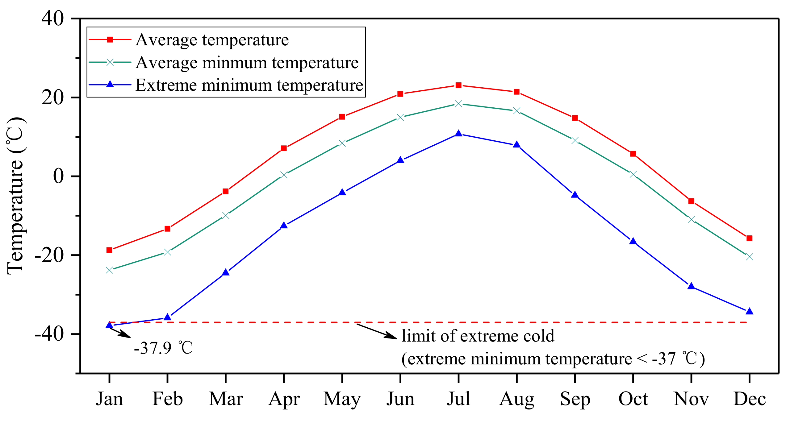
In October 2014, a 200-m test section of slab track with an asphalt waterproofing layer was constructed in northeastern China. Figure 4 shows the layout of MAWL on subgrade surface of high-speed railway track. The test section was implemented as part of the Harbin–Qiqihar passenger-dedicated line under the support of China Academy of Railway Sciences (CARS) and China Railway Corporation. The Harbin–Qiqihar passenger-dedicated railway line is the second high-speed railway line located in an extremely cold region in China; the first is the Harbin–Dalian high-speed railway line, which was completed in 2012. In the standard of China, namely the Technical Specifications for Construction of Highway Asphalt Pavement, the climate regions of asphalt pavement are divided according to the annual extreme minimum temperature. The region with the extreme minimum temperature lower than −37 °C is defined as extremely cold region, and the region with the extreme minimum temperature between −37 °C and −21 °C is defined as the cold region. Figure 5 shows the annual weather averages of the test site based on 30 years of statistics, where the extreme minimum temperature drops to −37.9 °C in January, which already enters the range of extremely cold (<−37 °C). The design speed of the test section is 250 km/h, and it was finished at the end of 2014 and has been in operation since August of 2015. The construction of the test section aims to validate the feasibility of the asphalt waterproofing layer under practical train load and environment conditions.
3.1. Material Preparation and Paving
The mastic asphalt applied in the test section was produced on the basis of laboratory design. Mastic asphalt was firstly mixed in a mixing plant at the temperature of 180–200 °C, then the initially mixed mastic asphalt was transferred to the mastic asphalt cooker for secondary mixing and transportation to the construction site. The temperature of the mastic asphalt cooker was controlled within the range of 200–240 °C, and the asphalt mastic was mixed at low speed in the cooker for at least 40 min. At the same time, to avoid aging of the asphalt, the mixing time was limited to no more than 4 h.
Due to small construction volume as well as a limited working face, the MAWL in the test section was paved utilizing small construction machinery. The prepared fresh mastic asphalt was first taken from the cooker to a large transfer hopper, then it was lifted to the worksite and mastic asphalt was released to the working face. Finally, the mixture was leveled to get a uniform thickness and smooth surface, as shown in Figure 6.
For quality control in the site, fluidity was adopted as the controlling index, and the Lueer test was performed on every truck of prepared mastic asphalt. Meanwhile, the field permeation test was performed after construction, and air voids were also measured on the cores drilled from completed MAWL. The results of field tests are shown in Table 3. The fluidity values varied slightly with different trucks, but they were always well controlled within the allowable range. Both of the air voids and permeability coefficient were smaller than that of laboratory tests, indicating good construction quality of the test section.
3.2. Joints Treatment
Because the MAWL is discontinuous along the cross section of slab track system, good bonding of construction joints between the asphalt layer and concrete track slab is critical for stability and durability of the whole waterproofing system. The train-induced vibration may cause frequent shearing motion between the asphalt layer and track slab. To further prevent the failure of the interface during its service life, a series of measures, including cross slope controlling and asphalt binder grouting, were implemented during the construction process. Cross slope of the asphalt waterproofing layer was strictly controlled at 4%, so as to assure good surface drainage and prevent possible moisture-induced damage. A V-shaped groove was cut in the area of joints after paving of the asphalt waterproofing layer, then the groove was cleaned and carefully grouted with hot asphalt binder. Figure 7 shows the grooving process and grouted joint.
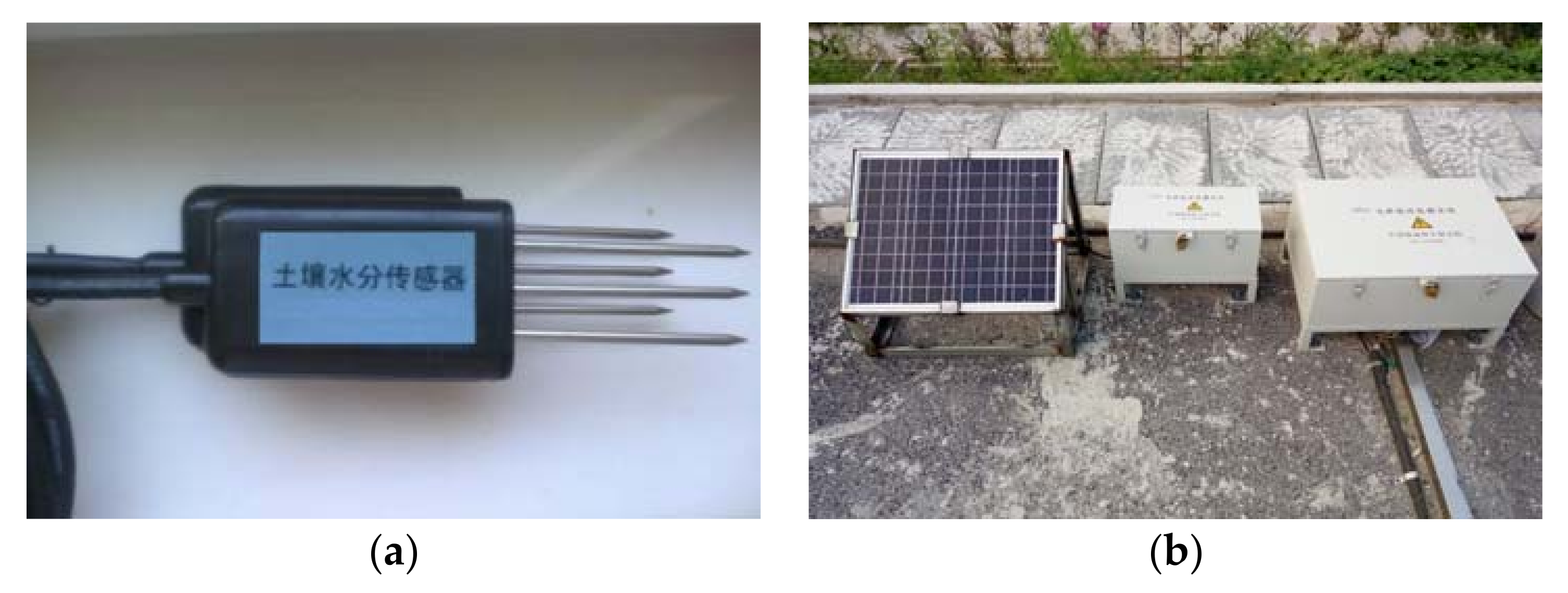
3.3. Water Content Monitoring System
During the construction process, a large number of water content sensors were placed inside the subgrade at a depth of 0.25 m (from the top surface of subgrade) to monitor the variation of water content after completion. The water content sensor used in this study was a frequency domain reflectometry (FDR) moisture sensor, by which the dielectric constant of the surrounding soil can be obtained through measuring the operating frequency of an oscillating circuit, whereby the volumetric water content can be measured indirectly. Figure 8a shows the photo of the FDR water content sensor used in this study. A data collecting system designed by CARS, as shown in Figure 8b, was adopted to collect monitoring data, and a solar panel was installed to power the system as well as the sensors. Two monitoring cross sections were set within the MAWL test section, and one monitoring cross section was set in an adjacent normal section (with concrete waterproofing layer) as well. As shown in Figure 9, for each monitoring cross section, water content sensors were separately buried beneath line center and the inner edge of slab track. The data collecting system records water content automatically, then the recorded data can be instantly delivered to the server in the laboratory.
4. Field Validation
4.1. Investigation of Surface Condition
Two field investigations were carried out since the completion of the test section, in November of 2015 and August of 2017, respectively. Field investigations aimed to evaluate the serviceability of MAWL. Thermal cracking and construction joint failure due to weak bonding are the main distresses resulting in poor waterproofing performance of the waterproofing layer, therefore, cracking and construction joint failure of the test section were mainly investigated in comparison with the conventional concrete waterproofing layer. Due to security reasons, the field investigations were carried out at midnight, during which no trains were scheduled on the high-speed railway line. All the visible cracks of MAWL within the 200 m test section were measured and recorded, including its width and length. The number of construction joint failure spots was also recorded. At the same time, a field investigation was also conducted on an adjacent 200-m normal section.
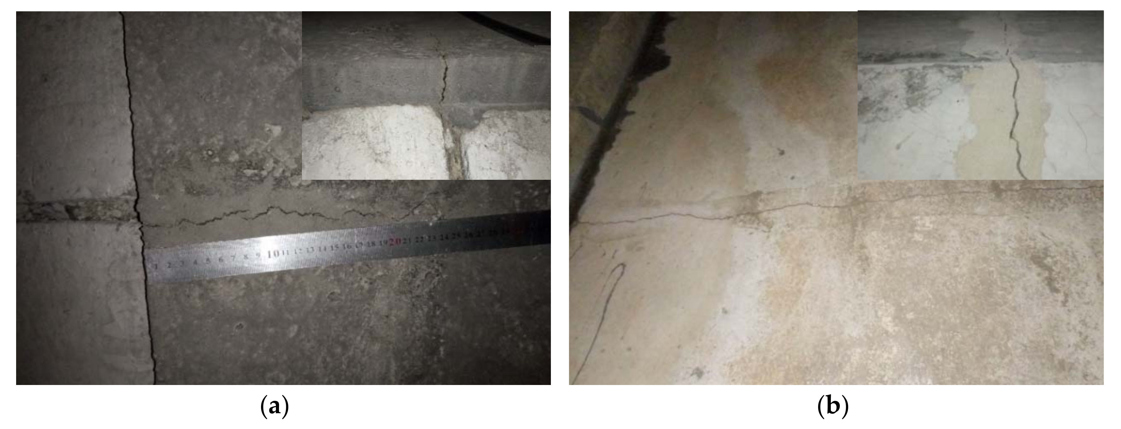
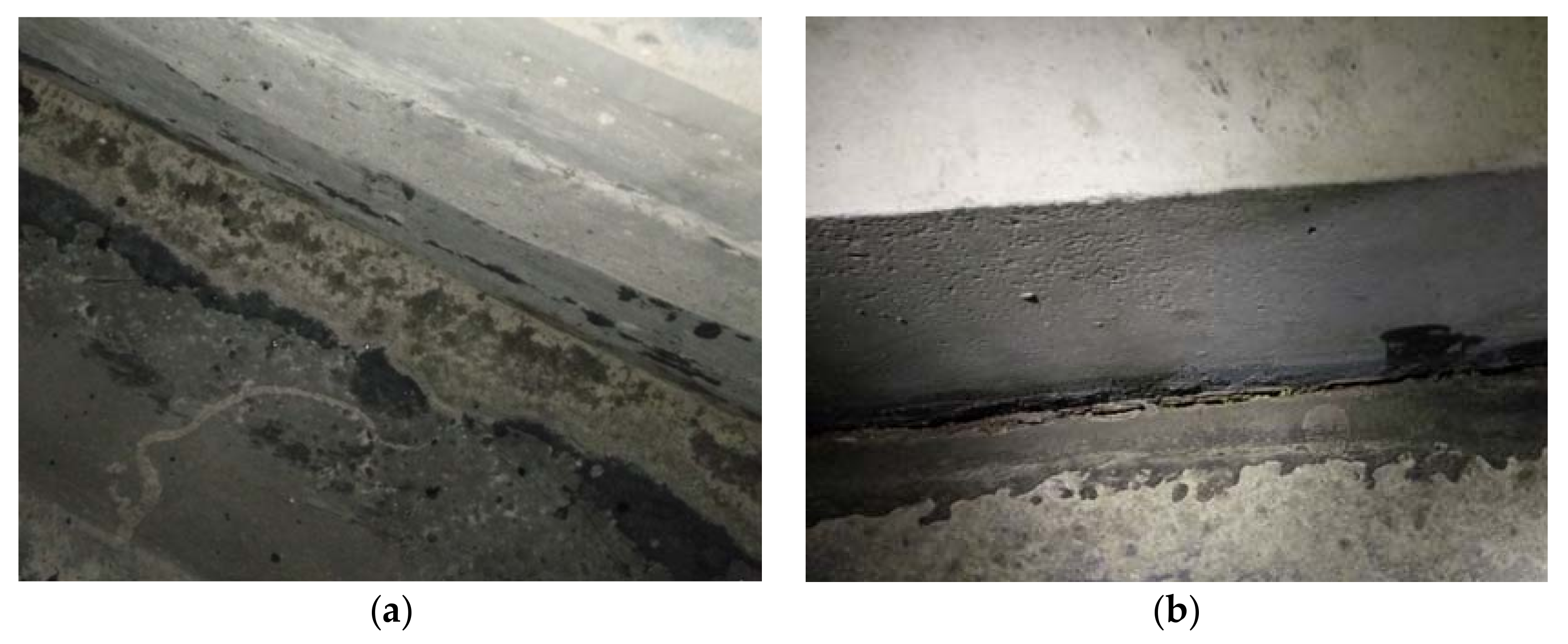
The investigation results show that lateral thermal cracking is the major distresses of both mastic asphalt and concrete waterproofing layers. In the meantime, cracks are more frequently observed on the shoulder than the middle area between track slabs. The majority of the cracks in mastic asphalt layer are short cracks developed from the outside edge of the shoulder, and they usually occur at the position above the construction joints of the concrete side slope (Figure 10). The expansion of construction joints, which is caused by the contraction of the concrete side slope, results in cracking of the waterproofing layer, while the cracks in the concrete waterproofing layer are mostly long cracks that cut through the whole cross section.
The features of cracks measured in two field investigations are shown in Figure 11. Details, including length, width, and number of cracks within the mastic asphalt waterproofing layer, are listed. Cracks in the 200 m of normal concrete waterproofing layer are shown in the figure as well. In the field investigation of November 2015, the majority of cracks in the test section were shorter than 60 cm, and their width varied from 0.5 mm to 2.0 mm, while, for the normal section, the total number of recorded cracks within 200 m was much higher than that of the test section, and half of the cracks cut through the whole cross section of waterproofing layer (250 cm long). The results of the field investigation in August 2017 indicate that the distribution of cracks in the test section is roughly the same as that of 2015, some of the cracks even turn out to be narrower and shorter, benefitting from the self-healing property of asphalt mixture. However, the number of cracks in the 200-m normal section increased sharply from November 2015 to August 2017, and all the cracks recorded in August 2017 cut through the cross section of waterproofing layer. Moreover, after two years of operation, most part of the construction joint between MAWL and concrete base maintained in good condition (Figure 12a), only several local cracks resulted by debonding were found, as shown in Figure 12b.
4.2. Subgrade Water Content Monitoring Results
The variation of subgrade water content during two years after construction was recorded through buried water content sensors. All the sensors were buried in the depth of 0.25 m from the top of the subgrade, and the layout of water sensors is shown in Figure 9. As the surface water relies on precipitation, the precipitation data acquired from the local weather station are shown in Figure 13 for reference. Figure 13 shows the subgrade water content variations in the line center, left and right side of slab track of three different cross sections, namely cross Section 1, Section 2 and Section 3.
As the test section is located in a seasonally frozen area, the water content of subgrade is influenced by two factors, namely the freezing of water and penetration of surface water. The subgrade water content remains at a low level during winter, due to partially frozen subgrade water, and it increases to a relatively high level after thawing in spring, then the value is mainly affected by penetration of surface water. There is an obvious difference between subgrade water content variation of the test section and the normal section. From the field monitoring data, the subgrade water content in both cross sections of test section is much more stable than the subgrade water content of the cross section in the normal section, indicating better waterproofing performance of MAWL. Meanwhile, the data from line center are always more stable than the data from slab side, which is consistent with the results of field investigation, that is, there are fewer cracks in the middle area than in the shoulder.
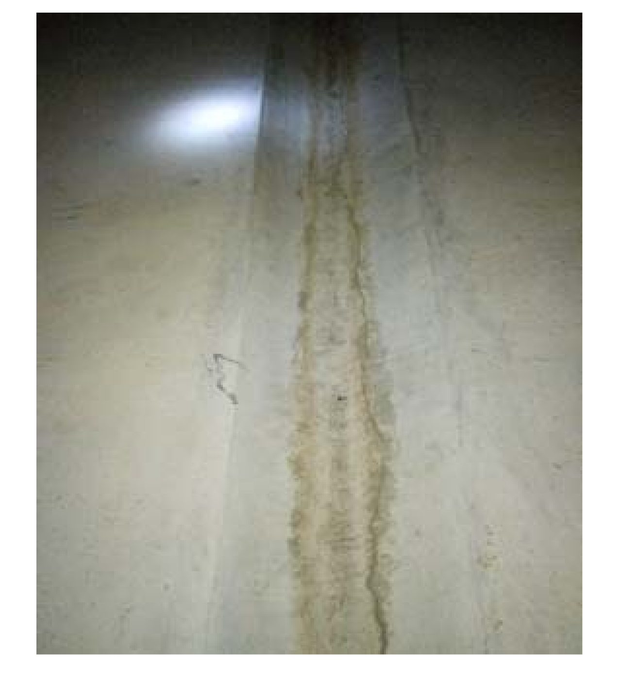
The waterproof performance of the concrete waterproofing layer obviously deteriorates over time. The increase and extension of cracks reduce its capability of preventing surface water penetration, thus it becomes easier for the surface water to penetrate into subgrade after raining, and it also takes longer time for the seepage water to get out of subgrade via evaporation. As shown in Figure 14, for concrete waterproofing layer in normal section, the amplitude of fluctuation of subgrade water content in 2016 became larger than that of 2015, indicating that subgrade water content became more sensitive to precipitation in the past two years. It is necessary to point out that the measured water content of right side of cross Section 3 is obviously higher than the other two lines, which is caused by the special position of the sensor. As shown in Figure 15, a water groove was built right over the water content sensor in the right side of cross Section 3, and, unfortunately, a cutting-through crack was found on the bottom of the grove. Therefore, the surface water will be collected into the water grove in rainy days, which facilitates the water penetration through the crack, resulting higher subgrade water content than the other two cross sections.
The overall behavior of MAWL in the test section was much better than concrete waterproofing layer in the normal section. The subgrade water content in most monitoring points of the test section always remained at a stable level during the two years of the monitoring period. The mastic asphalt waterproofing layer showed good waterproofing performance in both winter and summer days. However, cases of deterioration were also found in the test section. On the right side of cross Section 1, as shown in Figure 14c, the subgrade water content increased slightly after heavy rains in 2015, while the fluctuation became larger in 2016. To find the causes, a closer examination was done around this area during the field investigation in August 2017, and construction joint failure was determined to be the main reason. Overall, on one hand, the investigation results suggest good performance of MAWL in the slab track system; on the other hand, this would suppose that further observation of the test section is needed to evaluate the stability of MAWL. The continued filed investigation is also required to evaluate the long-term deterioration caused by climatic factors [36,37].
5. Conclusions
In this paper, mastic asphalt was designed and practically validated for application as a waterproofing layer on the subgrade surface of high-speed railway tracks in cold regions. The overall performance of mastic asphalt mixture was first evaluated by laboratory tests, then a test section of MAWL was constructed as part of real high-speed railway line, and water content sensors were placed inside the subgrade of test section to monitor the performance of MAWL. Based on the field investigation results and monitoring data during the two years of operation, the following conclusions can be drawn:
- Application of mastic asphalt significantly improves the waterproof performance of waterproofing layer beside the slab track system, and therefore helps to reduce freeze-thaw damage;
- MAWL outperforms conventional concrete waterproofing layer due to better cracking resistance, the observed cracks in MAWL are mostly short cracks caused by the expansion of construction joints in the concrete side slope;
- MAWL showed relatively high stability during the two years of investigation period, no obvious deterioration was observed in the test section;
- Construction joint failure is the key problem of existing discontinuous MAWL in slab track system, and further study is still needed to improve existing practices.
Author Contributions
S.L. performed the laboratory tests, analyzed the data and wrote the draft paper. J.Y. revised the manuscript and provided many valuable suggestions. X.C. directed this research work and improved the manuscript. G.Y. and D.C. assisted the implementation of test section and collection of field data.
Acknowledgments
This project has received funding from National Natural Science Fund of China (project number 51778136, 51778140), the Fundamental Research Funds for the Central Universities, and Jiangsu Innovation Program for College Graduates (project number KYLX16_0267).
Conflicts of Interest
The authors declare no conflict of interest.
References
- Li, Q.; Ling, X.; Zhang, F.; Wang, J. The effect of subgrade inhomogeneity induced by freeze-thaw on the dynamic response of track-subgrade system. Sci. Cold Arid Reg. 2013, 5, 554–561. [Google Scholar]
- Yu, X.B.; Liu, Y.; Gonzalez, J.; Yu, B. A new TDR sensor for accurate freeze-thaw measurement. Int. J. Pavement Eng. 2012, 13, 523–534. [Google Scholar] [CrossRef]
- Wang, H.Y.; Silvast, M.; Markine, V.; Wiljanen, B. Analysis of the dynamic wheel loads in railway transition zones considering the moisture condition of the ballast and subballast. Appl. Sci. 2017, 7, 1208. [Google Scholar] [CrossRef]
- Niu, F.; Li, A.; Luo, J.; Lin, Z.; Yin, G.; Liu, M.; Zheng, H.; Liu, H. Soil moisture, ground temperatures, and deformation of a high-speed railway embankment in northeast China. Cold Reg. Sci. Technol. 2017, 133, 7–14. [Google Scholar] [CrossRef]
- Wang, Z.; Yang, J.; Chen, X. Mastic asphalt concrete waterproof layer on high-speed railway subgrade in cold regions. In Proceedings of the Transportation Research Board 94th Annual Meeting, Washington, DC, USA, 11–15 January 2015; Transportation Research Board: Washington, DC, USA, 2015. [Google Scholar]
- Liu, S.; Yang, J.; Chen, X.; Wang, M.; Zhou, W. Design of asphalt waterproofing layer for high-speed railway subgrade: A case study in Heilongjiang province, China. In Proceedings of the Transportation Research Board 96th Annual Meeting, Washington, DC, USA, 8–12 January 2017; Transportation Research Board: Washington, DC, USA, 2017. [Google Scholar]
- Lee, S.H.; Lee, J.W.; Park, D.W.; Vo, H.V. Evaluation of asphalt concrete mixtures for railway track. Constr. Build. Mater. 2014, 73, 13–18. [Google Scholar] [CrossRef]
- Rose, J.G.; Teixeira, P.F.; Ridgway, N.E. Utilization of Asphalt/Bituminous Layers and Coatings in Railway Trackbeds—A Compendium of International Applications; Amer Soc Mechanical Engineers: New York, NY, USA, 2010; pp. 239–255. [Google Scholar]
- Sol-Sanchez, M.; Pirozzolo, L.; Moreno-Navarro, F.; Rubio-Gamez, M.C. A study into the mechanical performance of different configurations for the railway track section: A laboratory approach. Eng. Struct. 2016, 119, 13–23. [Google Scholar] [CrossRef]
- Sol-Sánchez, M.; D’Angelo, G. Review of the design and maintenance technologies used to decelerate the deterioration of ballasted railway tracks. Constr. Build. Mater. 2017, 157, 402–415. [Google Scholar] [CrossRef]
- Teixeira, P.F.; Pita, A.L.; Ferreira, P.A. New possibilities to reduce track costs on high-speed lines using a bituminous sub-ballast layer. Int. J. Pavement Eng. 2010, 11, 301–307. [Google Scholar] [CrossRef]
- Ferreira, T.M.; Teixeira, P.F.; Cardoso, R. Impact of bituminous subballast on railroad track deformation considering atmospheric actions. J. Geotech. Geoenviron. Eng. 2011, 137, 288–292. [Google Scholar] [CrossRef]
- Rose, J.G.; Souleyrette, R. Hot-Mix Asphalt (Bituminous) Railway Trackbeds: In-Track Tests, Evaluations, and Performances-a Global Perspective: Part Ii-United States Asphalt Trackbed Applications and Practices; Crc Press-Taylor & Francis Group: Boca Raton, FL, USA, 2014; pp. 683–690. [Google Scholar]
- Rose, J.G.; Souleyrette, R. Hot-Mix Asphalt (Bituminous) Railway Trackbeds: In-Track Tests, Evaluations, and Performances-a Global Perspective: Part Iii-Us Asphalt Trackbed Materials Evaluations and Tests; CRC Press-Taylor & Francis Group: Boca Raton, FL, USA, 2014; pp. 691–700. [Google Scholar]
- Chupin, O.; Martin, A.; Piau, J.M.; Hicher, P.Y. Calculation of the dynamic response of a viscoelastic railway structure based on a quasi-stationary approach. Int. J. Solids Struct. 2014, 51, 2297–2307. [Google Scholar] [CrossRef]
- Cardona, D.R.; Di Benedetto, H.; Sauzeat, C.; Calon, N.; Saussine, G. Use of a bituminous mixture layer in high-speed line trackbeds. Constr. Build. Mater. 2016, 125, 398–407. [Google Scholar] [CrossRef]
- Ferreira, P.A.; López-Pita, A. Numerical modelling of high speed train/track system for the reduction of vibration levels and maintenance needs of railway tracks. Constr. Build. Mater. 2015, 79, 14–21. [Google Scholar] [CrossRef]
- Ferreira, T.M.; Teixeira, P.F. Rail track performance with different subballast solutions: Traffic and environmental effects on subgrade service life. J. Transp. Eng. 2012, 138, 1541–1550. [Google Scholar] [CrossRef]
- Momoya, Y.; Sekine, E. Performance-based design method for railway asphalt roadbed. Doboku Gakkai Ronbunshuu E 2007, 63, 608–619. [Google Scholar] [CrossRef]
- Lee, S.H.; Choi, Y.T.; Lee, H.M.; Park, D.W. Performance evaluation of directly fastened asphalt track using a full-scale test. Constr. Build. Mater. 2016, 113, 404–414. [Google Scholar] [CrossRef]
- Lechner, B. Developments in road pavement construction and railway track technology for a sustainable surface transportation infrastructure. In Proceedings of the 8th International Conference of Chinese Logistics and Transportation Professionals, Chengdu, China, 8–10 October 2008; American Society of Civil Engineers: Reston, VA, USA, 2008; pp. 2656–2665. [Google Scholar]
- Lee, S.H.; Vo, H.V.; Park, D.W.; Na, I.H. Comparisons of structural behavior between level and cant area of asphalt concrete track. Constr. Build. Mater. 2017, 153, 578–587. [Google Scholar] [CrossRef]
- Li, Q.S.; Ding, H.B.; Rahman, A.; He, D.P. Evaluation of basic oxygen furnace (BOF) material into slag-based asphalt concrete to be used in railway substructure. Constr. Build. Mater. 2016, 115, 593–601. [Google Scholar] [CrossRef]
- Yang, E.; Wang, K.C.P.; Qiu, Y.; Luo, Q. Asphalt concrete for high-speed railway infrastructure and performance comparisons. J. Mater. Civ. Eng. 2016, 28, 04015202. [Google Scholar] [CrossRef]
- Yang, E.H.; Wang, K.C.P.; Luo, Q.; Qiu, Y.J. Asphalt concrete layer to support track slab of high-speed railway. Transp. Res. Record 2015, 2505, 6–14. [Google Scholar] [CrossRef]
- Research Institute of Highway Ministry of Transport. Technical Specifications for Construction of Highway Asphalt Pavements; China Communications Press: Beijing, China, 2004; JTG F40-2004. [Google Scholar]
- Research Institute of Highway Ministry of Transport. Standard Test Methods of Bitumen and Bituminous Mixtures for Highway Engineering; China Communications Press: Beijing, China, 2011; JTG E20-2011. [Google Scholar]
- Qian, J.S.; Wang, Q.Z.; Wu, W.J.; Zhang, H. Fatigue performance of gussasphalt concrete made from modified ahAH-70# asphalt. Mater. Des. 2013, 52, 686–692. [Google Scholar]
- Rahman, A.; Ai, C.F.; Xin, C.F.; Gao, X.W.; Lu, Y. State-of-the-art review of interface bond testing devices for pavement layers: Toward the standardization procedure. J. Adhes. Sci. Technol. 2017, 31, 109–126. [Google Scholar] [CrossRef]
- Kim, T.W.; Baek, J.; Lee, H.J.; Choi, J.Y. Fatigue performance evaluation of SBS modified mastic asphalt mixtures. Constr. Build. Mater. 2013, 48, 908–916. [Google Scholar] [CrossRef]
- Wang, H.; Li, G. Study of factors influencing gussasphalt mixture performance. Constr. Build. Mater. 2015, 101, 193–200. [Google Scholar] [CrossRef]
- Lee, S.H.; Park, D.W.; Vo, H.V.; Dessouky, S. Asphalt mixture for the first asphalt concrete directly fastened track in Korea. Adv. Mater. Sci. Eng. 2015, 2015, 701940. [Google Scholar] [CrossRef]
- Zhu, S.Y.; Cai, C.B. Interface damage and its effect on vibrations of slab track under temperature and vehicle dynamic loads. Int. J. Non-Linear Mech. 2014, 58, 222–232. [Google Scholar] [CrossRef]
- Zhao, H.D.; Cao, J.F.; Zheng, Y. Investigation of the interface bonding between concrete slab and asphalt overlay. Road Mater. Pavement Design 2017, 18, 109–118. [Google Scholar] [CrossRef]
- Song, W.; Shu, X.; Huang, B.; Woods, M. Influence of interface characteristics on the shear performance between open-graded friction course and underlying layer. J. Mater. Civ. Eng. 2017, 29, 04017077. [Google Scholar] [CrossRef]
- Sol-Sanchez, M.; Moreno-Navarro, F.; Garcia-Trave, G.; Rubio-Gamez, M.C. Laboratory study of the long-term climatic deterioration of asphalt mixtures. Constr. Build. Mater. 2015, 88, 32–40. [Google Scholar] [CrossRef]
- Sol-Sanchez, M.; Pirozzolo, L.; Moreno-Navarro, F.; Rubio-Gamez, M.C. Advanced characterisation of bituminous sub-ballast for its application in railway tracks: The influence of temperature. Constr. Build. Mater. 2015, 101, 338–346. [Google Scholar] [CrossRef]
Figure 1.
Gradation of mastic asphalt.
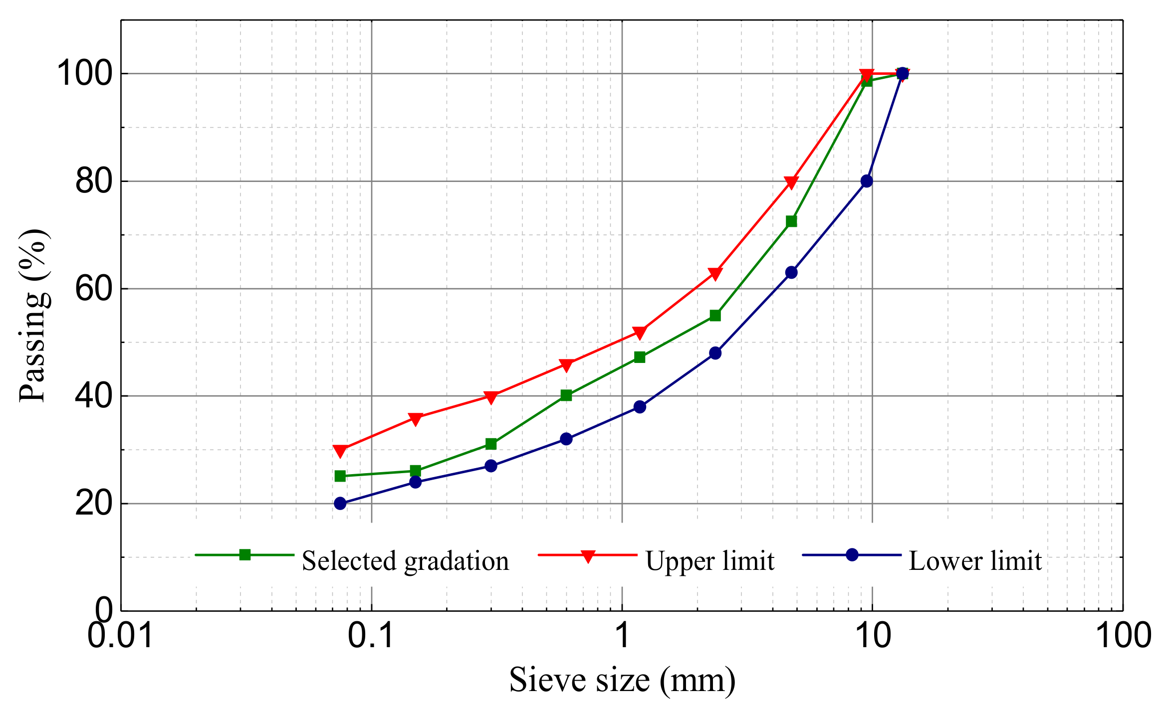
Figure 2.
Samples prepared for laboratory tests: (a) beams for bending test; (b) slabs for permeation and rutting test; (c) composite cube samples for the shear test; and (d) slant shear test device.
Figure 2.
Samples prepared for laboratory tests: (a) beams for bending test; (b) slabs for permeation and rutting test; (c) composite cube samples for the shear test; and (d) slant shear test device.
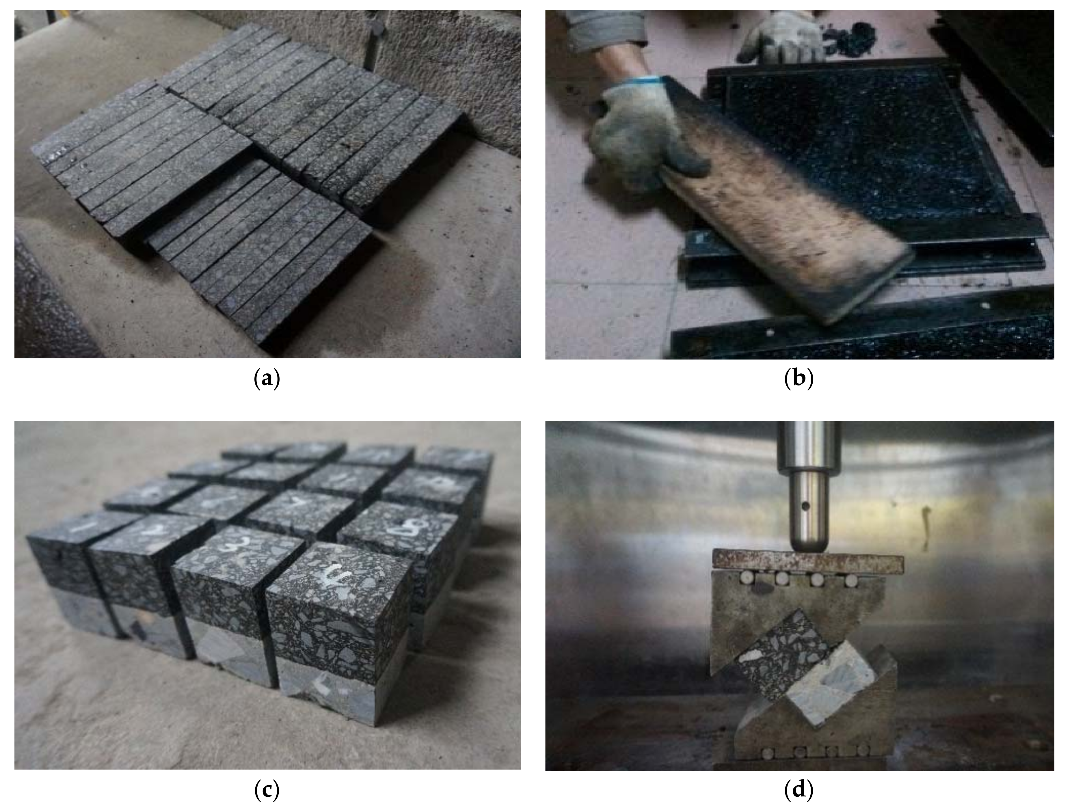
Figure 3.
Apparatus for Lueer test.
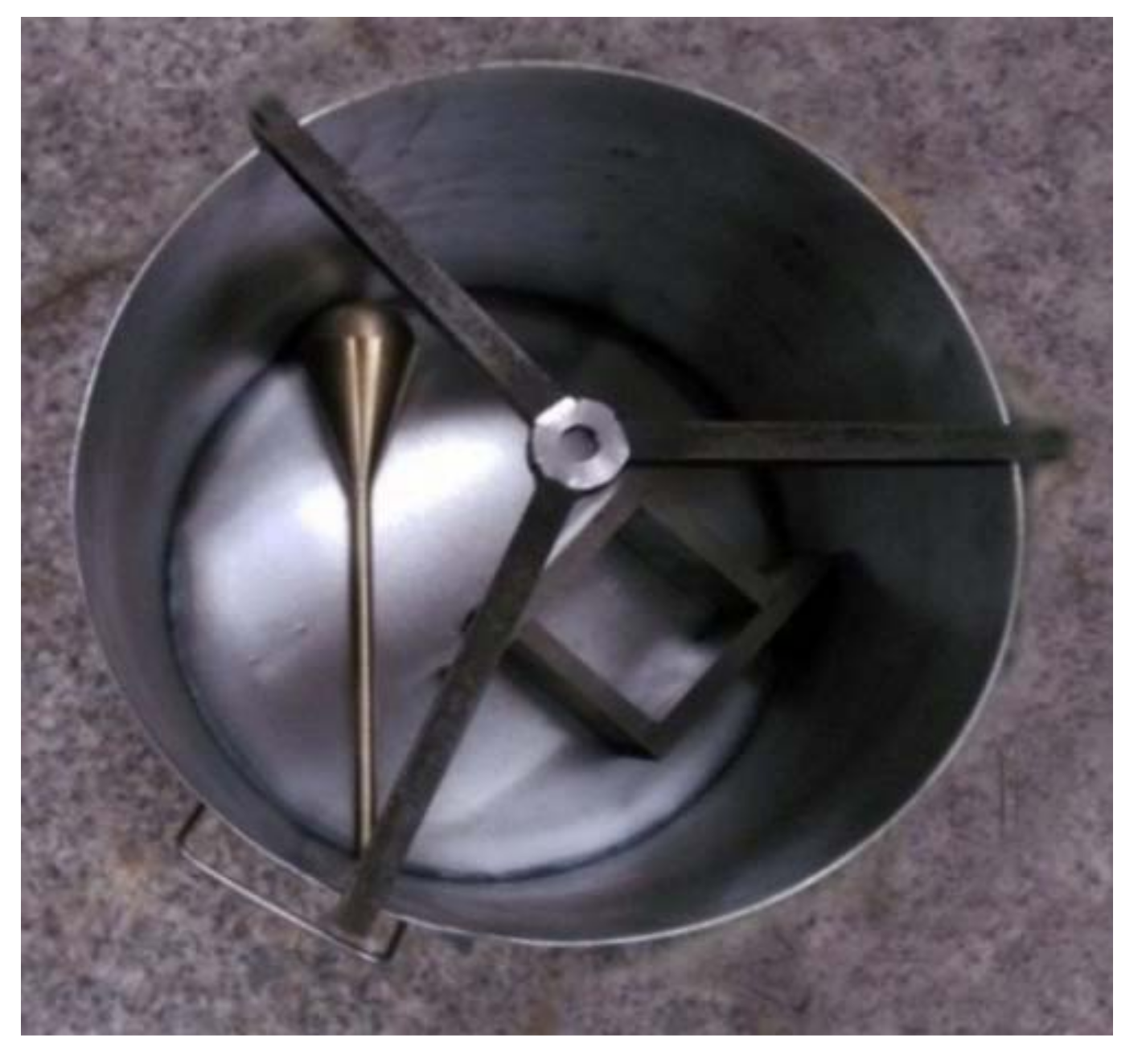
Figure 4.
The layout of mastic asphalt waterproofing layer (MAWL) on subgrade surface of high-speed railway track.
Figure 4.
The layout of mastic asphalt waterproofing layer (MAWL) on subgrade surface of high-speed railway track.
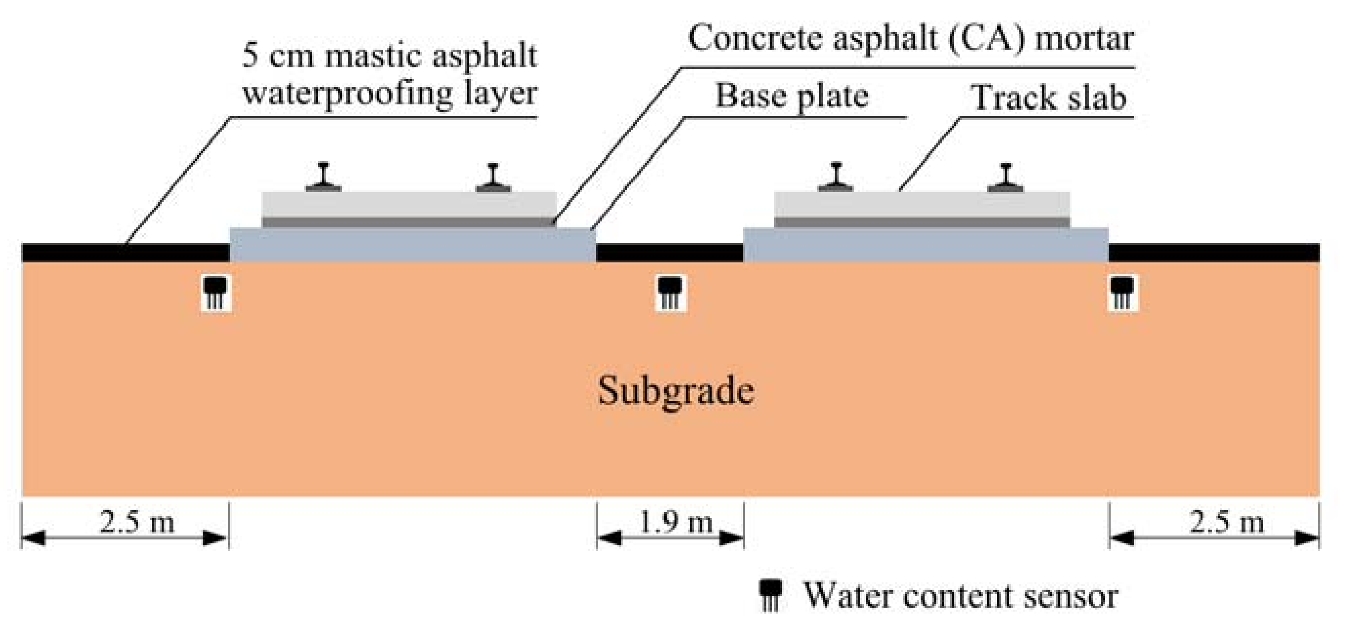
Figure 5.
Annual weather averages of the test site.

Figure 6.
Construction process (a) and competed surface (b) of mastic asphalt waterproofing layer (MAWL).
Figure 6.
Construction process (a) and competed surface (b) of mastic asphalt waterproofing layer (MAWL).
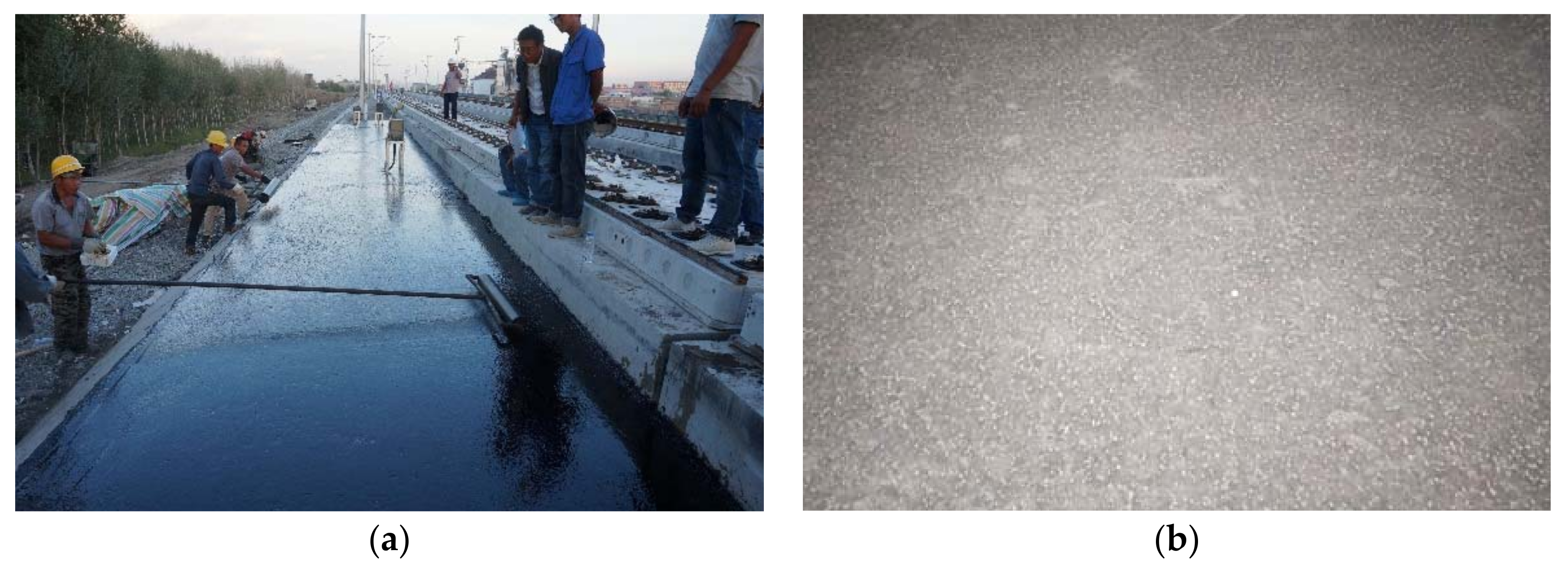
Figure 7.
Joint treatment process: (a) V-shaped groove; and (b) and grouted joint.
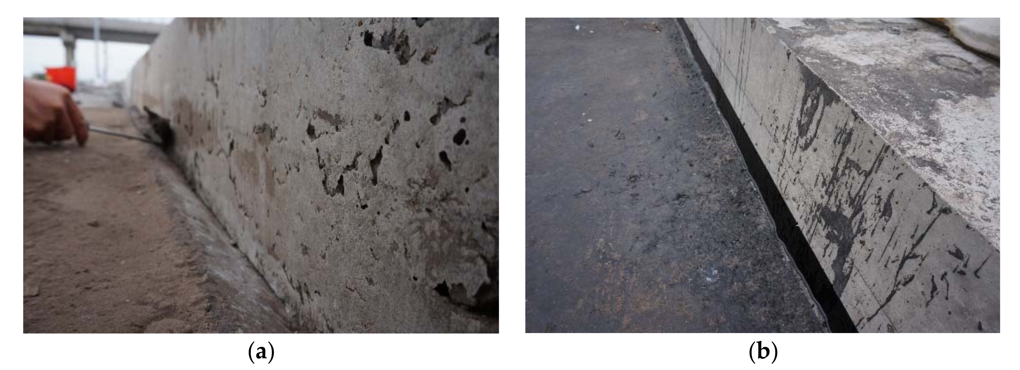
Figure 8.
(a) Frequency domain reflectometry (FDR) water content sensors; and (b) data collecting system.
Figure 8.
(a) Frequency domain reflectometry (FDR) water content sensors; and (b) data collecting system.

Figure 9.
The layout of water content sensor in test section and normal section (cross Section 1, Section 2, Section 3).
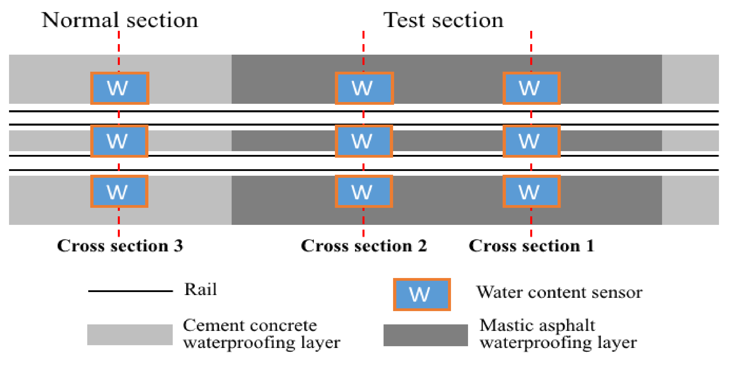
Figure 10.
Typical cracking of (a) mastic asphalt waterproofing layer; and (b) concrete waterproofing layer.
Figure 10.
Typical cracking of (a) mastic asphalt waterproofing layer; and (b) concrete waterproofing layer.

Figure 11.
Features of cracks measured in two times of field investigations: (a) November 2016; and (b) August 2017.
Figure 11.
Features of cracks measured in two times of field investigations: (a) November 2016; and (b) August 2017.

Figure 12.
Status of construction joint after two years of operation: (a) construction joint in good condition; and (b) local debonding of construction joint.
Figure 12.
Status of construction joint after two years of operation: (a) construction joint in good condition; and (b) local debonding of construction joint.

Figure 13.
Precipitation data obtained from the weather station near the test section.
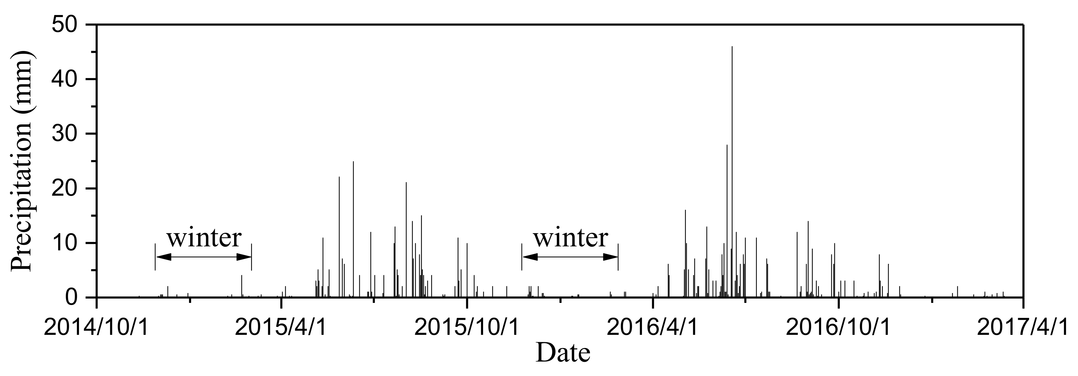
Figure 14.
Monitoring data of subgrade water content: (a) the line center; (b) left side of the line; and (c) right side of the line.
Figure 14.
Monitoring data of subgrade water content: (a) the line center; (b) left side of the line; and (c) right side of the line.
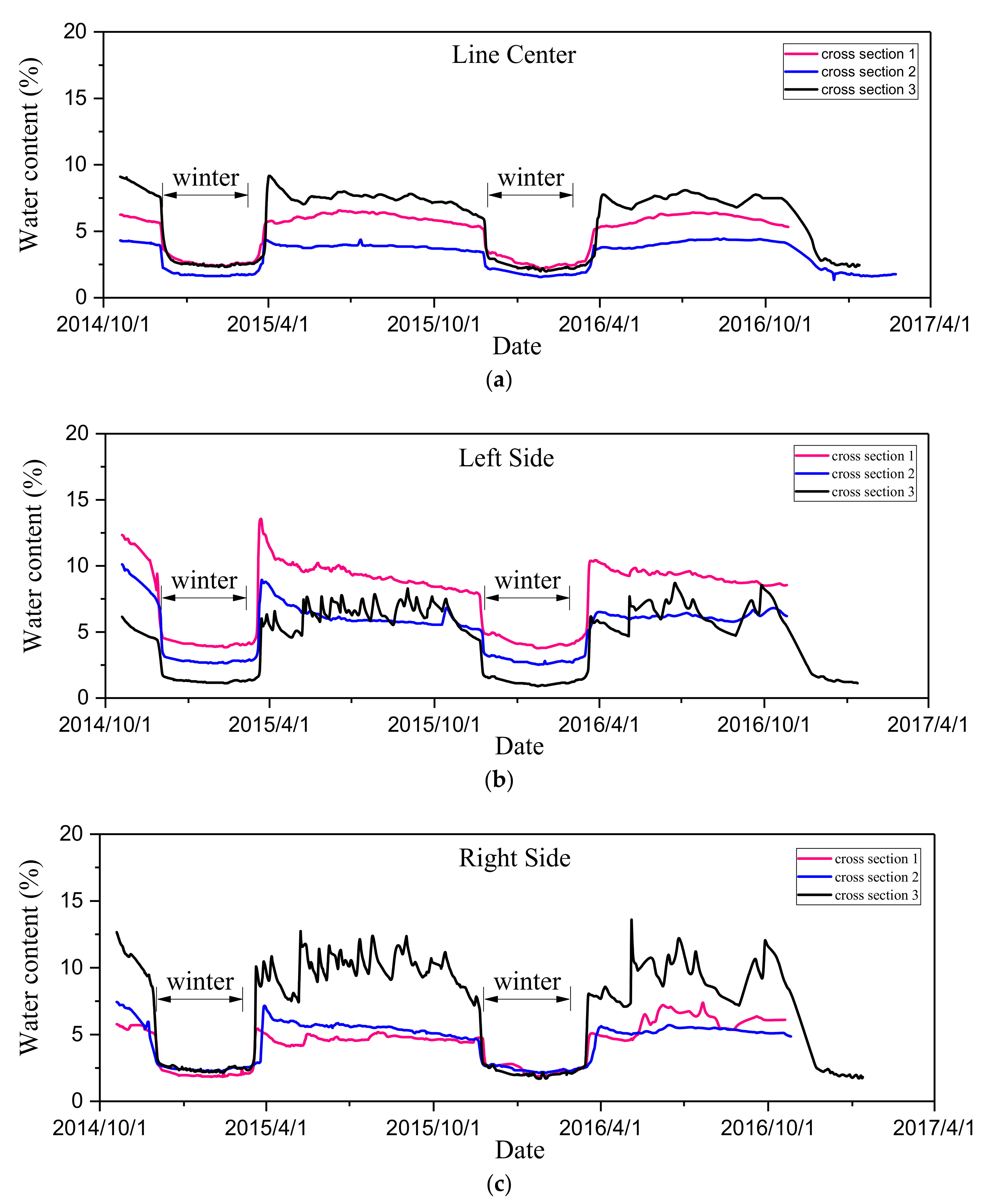
Figure 15.
Crack on the bottom of the water groove.


Table 1.
Tested indexes of asphalt.
| Indexes | Test Results | Requirements |
|---|---|---|
| Penetration (25 °C, 5 s, 100 g), 0.1 mm | 104 | >80 |
| Penetration index (PI) | 0.60 | ≥−0.8 |
| Ductility at 5 °C, cm | 72.8 | ≥40 |
| Softening point (R & B), °C | 83 | ≥50 |
| Dynamic viscosity at 135 °C, Pa·s | 1.771 | ≤3 |
Table 2.
Results of laboratory tests.
| Test Methods | Index (Unit) | Tested Value | Requirements |
|---|---|---|---|
| Lueer test | Fluidity (s) | 10.5 | 5–40 |
| Air voids | Air void (%) | 1.8 | - |
| Permeation test | Permeability coefficient (ml/min) | 3 | - |
| Three-point bending beam test | Failure strain (−10 °C, με) | 5641 | >3000 |
| Rutting test | Dynamic stability (times/mm) | 2548 | >2000 |
| Slant shear test | Shear strength (25 °C, MPa) | 2.01 | - |
Table 3.
Results of field tests.
| Test Methods | Index (Unit) | Tested Value | Requirements | |
|---|---|---|---|---|
| Field | Laboratory | |||
| Lueer test | Fluidity (s) | <20 | 10.5 | 5–40 |
| Air voids of cores | Air void (%) | <1.13 | 1.8 | - |
| Field permeation test | Permeability coefficient (mL/min) | <1 | 3 | - |
© 2018 by the authors. Licensee MDPI, Basel, Switzerland. This article is an open access article distributed under the terms and conditions of the Creative Commons Attribution (CC BY) license (http://creativecommons.org/licenses/by/4.0/).
Share and Cite
MDPI and ACS Style
Liu, S.; Yang, J.; Chen, X.; Yang, G.; Cai, D. Application of Mastic Asphalt Waterproofing Layer in High-Speed Railway Track in Cold Regions. Appl. Sci. 2018, 8, 667. https://doi.org/10.3390/app8050667
AMA Style
Liu S, Yang J, Chen X, Yang G, Cai D. Application of Mastic Asphalt Waterproofing Layer in High-Speed Railway Track in Cold Regions. Applied Sciences. 2018; 8(5):667. https://doi.org/10.3390/app8050667
Chicago/Turabian StyleLiu, Song, Jun Yang, Xianhua Chen, Guotao Yang, and Degou Cai. 2018. "Application of Mastic Asphalt Waterproofing Layer in High-Speed Railway Track in Cold Regions" Applied Sciences 8, no. 5: 667. https://doi.org/10.3390/app8050667
Note that from the first issue of 2016, this journal uses article numbers instead of page numbers. See further details here.