Review

Overview of Lithium-Ion Battery Modeling Methods for State-of-Charge Estimation in Electrical Vehicles

1
School of Automation, Northwestern Polytechnical University, Xi’an 710072, China
2
Department of Energy, Aalborg University, 9220 Aalborg, Denmark
3
Lithium Balance A/S, 2765 Smørum, Denmark
*
Author to whom correspondence should be addressed.
Appl. Sci. 2018, 8(5), 659; https://doi.org/10.3390/app8050659
Submission received: 8 March 2018 / Revised: 13 April 2018 / Accepted: 20 April 2018 / Published: 25 April 2018
(This article belongs to the Special Issue Battery Management and State Estimation)

Abstract

:
As a critical indictor in the Battery Management System (BMS), State of Charge (SOC) is closely related to the reliable and safe operation of lithium-ion (Li-ion) batteries. Model-based methods are an effective solution for accurate and robust SOC estimation, the performance of which heavily relies on the battery model. This paper mainly focuses on battery modeling methods, which have the potential to be used in a model-based SOC estimation structure. Battery modeling methods are classified into four categories on the basis of their theoretical foundations, and their expressions and features are detailed. Furthermore, the four battery modeling methods are compared in terms of their pros and cons. Future research directions are also presented. In addition, after optimizing the parameters of the battery models by a Genetic Algorithm (GA), four typical battery models including a combined model, two RC Equivalent Circuit Model (ECM), a Single Particle Model (SPM), and a Support Vector Machine (SVM) battery model are compared in terms of their accuracy and execution time.

1. Introduction

As fossil fuel reserves continue to decrease, new means of transportation that are independent of traditional fuels have to be found to meet the requirements of our daily life. Consequently, electrical vehicles (EV) have been regarded as a potential solution. In order to increase the acceptance of EV in the market, the performance of the energy storage system has attracted much attention from both industry and academia. As the only power supply in pure EV, the capability of the battery pack is of great importance. Lithium-ion (Li-ion) batteries have higher energy density, longer cycle life, and no memory effect compared with other battery types [1,2]. Additionally, the price of the li-ion battery continues to decline, which makes it a popular choice for EV applications [3]. In order to ensure the safety and reliable operation of the battery pack, SOC has to be estimated [4,5].
Although numerous SOC estimation methods have been exhibited and classified in [6,7,8,9,10], accurate, efficient, and reliable SOC estimation solutions are still needed in real-time applications. As discussed in our previous work [10], SOC estimation methods are mainly divided into five categories: the Coulomb counting method; the Open Circuit Voltage (OCV) method; the impedance spectroscopy-based method; the model-based method, and the artificial neural network-based method. The Coulomb counting method calculates SOC through the integration of current, and has high computational efficiency. The accuracy of Coulomb counting method is sensitive to initial SOC and the accumulation of the current measurement error. OCV method depends on the relationship between SOC and OCV. The long battery relaxation time for measuring the OCV makes it impractical for most online SOC estimations. Impedance spectroscopy is hard to measure accurately, while artificial neural networks are closely related to the training samples. Generally, model-based SOC estimators are supposed to have a superior performance. However, their performance relies on an accurate battery model. In the model-based estimation structure, much attention has been paid to different estimation algorithms, while a complete review of the battery modeling methods is seldom seen in the literature. Therefore, this paper reviews important battery modeling methods from the SOC estimation point of view.
The modeling technologies for Li-ion batteries are discussed in [11], where data-driven battery models are not discussed. Battery modeling methods for EV are discussed in [12], but the paper does not give the detailed features of each method or the connections between each method. Different from previous works [11,12], this paper divides the battery modeling method into four categories: empirical model, Equivalent Circuit Model (ECM), electrochemical model, and data-driven model. According to the structure of the model-based estimation, the advantages and disadvantages of each modeling method are presented. In addition, the future trends for next-generation modeling technology are also presented. Moreover, four typical modeling methods in SOC estimation area including the combined model [13], two Resistance-Capacitance (RC) ECM [10], Single Particle Model (SPM) [14] and Support Vector Machine (SVM) battery model [15] are compared through an experiment on a LiFePO4 battery in terms of accuracy and computational efforts.
The rest of this paper is organized as follows. After introducing the principle of model-based SOC estimation, the features of the four modeling methods are detailed in Section 2. Section 3 gives the advantages and disadvantages of each modeling method and previews future trends in battery modeling methods. Four typical modeling methods are compared in terms of modeling accuracy and execution time in Section 4. Conclusions are drawn in Section 5.

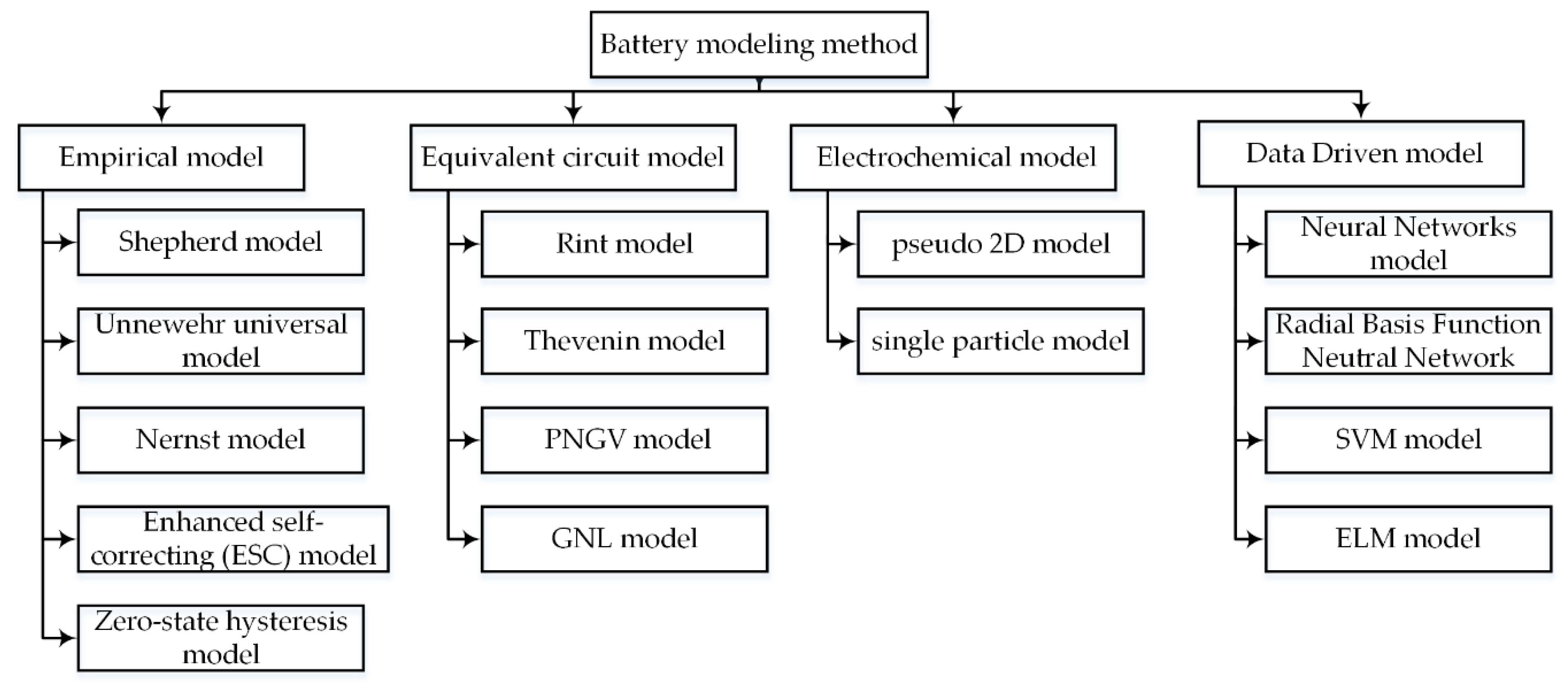
2. Battery Modeling Methods

In this section, the effect of the battery model on the accuracy of the model-based estimation is analyzed. Then, the features of each modeling method are detailed.

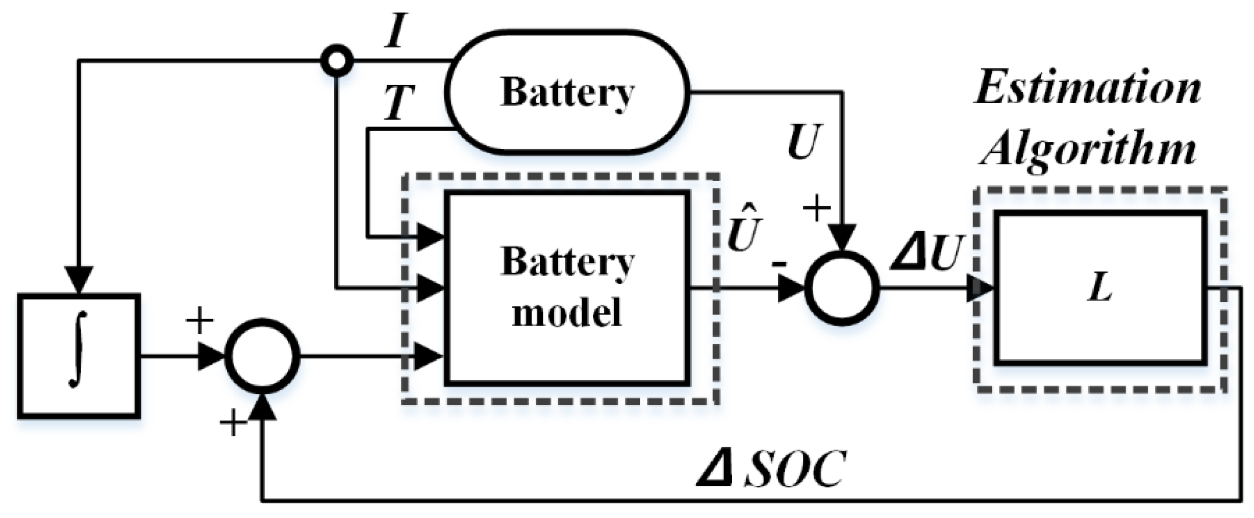
2.1. Battery Model and Model-Based SOC Estimation

The driving conditions of EVs are significantly different in different countries and regions [16], which means that the estimation methods should be able to accurately estimate SOC under diverse driving conditions [17]. Therefore, advanced SOC estimation methods with good robustness are needed for EVs. Model-based methods have frequently been used for the SOC estimation area due to their good accuracy and robustness. The structure of the model-based SOC estimation method is illustrated in Figure 1.
We see from Figure 1 that the model-based estimation consists of two major parts: a battery model and an estimation algorithm [14,15,18,19,20,21]. In the model-based estimation structure, a battery model is established to predict the terminal voltage, and the current, SOC, and temperature are the usual inputs. In order to clearly explain the process of model-based estimation, it is assumed that the battery model is exactly equivalent to the real battery and the measurement from sensors does not contain any noise. Therefore, if the real SOC is the input of the battery model, the predicted voltage of the battery model is expected to be the same as the measured terminal voltage. However, errors in SOC always exist in real applications. The deviation between the output of the battery model and the terminal voltage can be used to correct the SOC in each sampling time. Afterwards, the corrected SOC acts as the input of the battery model for the calculation of the terminal voltage in the next cycle. As discussed in [22], the SOC estimation error contains dynamic transient error and steady state error. The dynamic transient error can be small when using a large gain L in the estimation algorithm, while the errors related to the modeling accuracy are independent of L [22]. This means that the gain L cannot correct battery modeling errors. Therefore, an accurate battery model surely improves the accuracy of SOC estimation. The model-based SOC estimation methods are insensitive to the initial SOC due to the fact that it has a closed loop structure [10].
After pointing out the main function of the battery model in the model-based estimation structure, different kind of battery modeling methods are detailed in this section. According to their modeling principles, modeling methods are mainly divided into four categories: empirical models, ECMs, electrochemical models, and data-driven models.

2.2. Empirical Model

In empirical models, the battery terminal voltage is represented as a mathematical function of the SOC and the current [23]. Considered a simplified electrochemical model, an empirical model represents the essential nonlinear characteristics of a battery with reduced order polynomial or mathematical expressions.
In Table 1, y k is the terminal voltage, E 0 is OCV when the battery is fully charged, R i is the internal resistance, K1 is the polarization resistance, ik is the instantaneous current, and zk represents the battery SOC. The Shepherd model [24], the Unnewehr universal model [25,26], and the Nernst model [27] in Table 1 are the classical empirical models in the literature. The accuracy of the three models in predicting the terminal voltage is compared in [23]. The Nernst model obtains the best accuracy, and the Shepherd model performs especially well in a continuously discharging current. Generally, the three models in Table 1 can be combined for better accuracy in the following form [13]:
y k = E 0 R i k K 1 z k K 2 z k + K 3 ln ( z k ) + K 4 ln ( 1 z k ) .
There are other ways to improve the modeling accuracy of the basic empirical models. The accuracy of the empirical model can be improved by adding more parameters [28]. Since the Shepherd model suffers from algebraic loop and simulation instability in real-time applications, a modified Shepherd model is proposed for describing the dynamic behavior of the battery [29]. Replacing the voltage of the internal resistance with the polarization voltage term, it is validated under a constant current profile. In order to improve the dynamic performance of the modified Shepherd model, the OCV-SOC relationship is taken into consideration in [30] and a term related to the polarization voltage is added. The error band of the modified Shepherd model is within ± 5 % in the dynamic current profile. To further solve the singularity in the Shepherd model, another extension proposed in [31,32] obtains relative error below 0.5% in FTP72 cycles and the execution time is between 2.35 μs and 4.35 μs. The Nernst model can also be improved by adding two additional constants, τ 1 and τ 2 , to have a stronger ability to describe the dynamic terminal voltage [27]. Classical empirical models have flaws during the relaxation time [33] because the hysteresis effect [34] of the battery voltage is not considered. Therefore, the term s·M is added to the Nernst equation to represent the hysteresis effect, where M is the correction term to be identified [35]. Moreover, an enhanced self-correcting model considering the voltage hysteresis is proposed in [36], which includes the gradual hysteresis voltage as a function of SOC and the instantaneous hysteresis voltage changes with the sign of the current. Detailed expressions of the abovementioned empirical models are illustrated in Table 2. Considering more effects inside the battery, the accuracy of the empirical model is improved but the computational burden is also increased.

2.3. Equivalent Circuit Model

ECM consists of a voltage source related to SOC, an internal resistor, and Resistance-Capacitance (RC) networks, which is able to describe the electrical relationship between the inputs (current, SOC, and temperature) and the terminal voltage [37]. Compared to empirical models, ECMs are much easier for the understanding of the electrical characteristic of the battery. Moreover, due to the plentiful circuit components and their combinations, ECM gives researchers sufficient freedom to design a suitable structure for their applications. Generally, in ECM, the resistor indicates the self-discharge and the high-valued capacitor or the voltage source stands for the battery OCV. The RC pairs with different time constants stand for the diffusion process in electrolyte and porous electrodes and the charge transfer and double-layer effect in the electrode. The Rint model, Thevenin model, Partnership for a New Generation of Vehicles (PNGV) model, and General Non-Linear (GNL) model are the four common ECMs in the literature, and are illustrated in Table 3.
As seen from Table 3, the structures of the different ECMs have some connections. By adding an additional RC network to the Rint model, the Thevenin model is achieved and can better capture the dynamic terminal voltage of battery. Considering the effects of OCV variation, the PNGV model is obtained after adding a capacitor Ccap to the Thevenin model [39,40]. Ccap describes the OCV variation by the accumulation of the discharging current [43]. Adding more RC networks helps with describing the terminal voltage in more detail; the PNGV model usually has better accuracy than the Rint and Thevenin models. Compared with the Thevenin model, one more RC network is included in the GNL model by taking into account the concentration polarization effect. In terms of SOC estimation area, ECMs with one RC or two RC pairs are especially popular for modeling the battery. Twelve battery models including the empirical models and ECMs with different RCs are compared in terms of modeling accuracy, which proves that one RC ECM is more suitable for the LiNMC battery and one RC ECM with one-state hysteresis is the best choice for the LiFePO4 battery [44]. Ten lumped parameter models for Li-ion battery are compared in terms of modeling accuracy and the effects of the model on the SOC and State-of-Power (SOP) estimation are also discussed in [45]. The experimental results on the New European Drive Cycle (NEDC) show that two RC ECM is an optimal choice for the energy storage system and one RC ECM with hysteresis voltage is preferred for battery with strong hysteresis effect in the terminal voltage. Therefore, adding more RC networks generally improves the modeling accuracy, but having more than two RC networks also increases the computational burden.
ECMs can be modified in several ways to improve their ability to describe the terminal voltage. In order to describe the inherent electrochemical property of the battery, a physically based ECM is proposed through analyzing the Warburg element from the Electrochemical Impedance Spectroscopy (EIS) measurement [46]. The difficulty of online EIS measurement in real-time applications may decrease the accuracy of the physically based ECM. For a better interpretation of electrochemical and thermal behaviors, a multiphysical battery model with 11 parameters is proposed in [47]. The modeling accuracy is less than 2% for the electrical part and the mean error is 2.45% for the thermal part in the experimental test. For real applications, there should be a good tradeoff between the complexity and accuracy before applying ECM to a specific application.

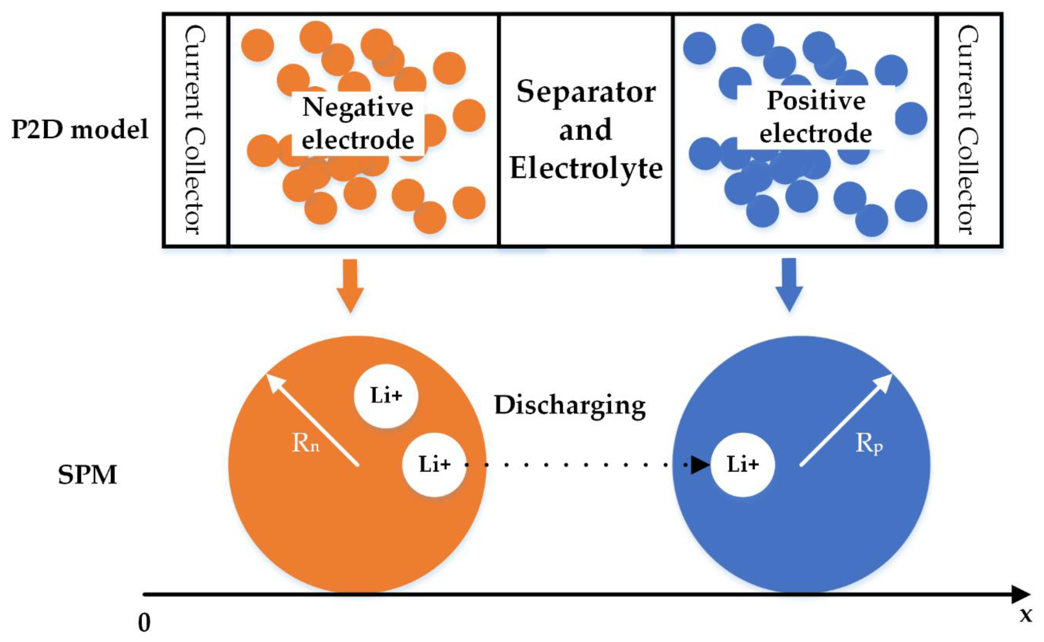
2.4. Electrochemical Model

According to the electrochemical kinetics and the charge transfer process, electrochemical models are established for the purpose of describing the inner reactions inside the battery. Electrochemical models are the foundation of a series of physical laws, such as Faraday’s first law, Ohm’s law, Fick’s law of diffusion, and the Butler–Volmer equation. The electrochemical model is expressed in a nonlinear Partial Differential Equations (PDEs) form. Therefore, in order to have a direct analytical solution, the prerequisite of using the electrochemical model is changing the PDEs into Ordinary Differential Equations (ODEs). Numerical methods such as integral approximation, Pade approximation, the Ritz method, the finite element method, and the finite difference method are often selected to discretize the nonlinear PDEs in the electrochemical models [47,48].
In Faraday’s law of electrolysis, the pore-wall flux Ji is related to the divergence of current flow in the electrolyte phase. The pore-wall flux is calculated as follows:
J n ( t ) = I ( t ) F S n ,   J p ( t ) = I ( t ) F S p ,
where n, p denote the negative and positive electrodes, respectively.
Ohm’s law indicates the distribution of potential between the electrolyte and the active material. Fick’s law of diffusion reveals the relationship of the concentration and the diffusion flux, which is capable of describing the diffusions in both the electrolyte and the electrode. The Butler–Volmer equation points out the impact of the electrode potential on the electrode current.
Two kinds of electrochemical models utilized in the literature are the pseudo-2D model and the Single Particle Model (SPM), as shown in Figure 2. The pseudo-2D model [49,50,51] is based on the concentrated solution theory and the porous electrode theory. The structure of the porous electrode increases the area of the specific surface, which adequately facilitates the electrochemical reactions. The active material is able to sufficiently contact the electrolyte with the benefit of the porous structure. Pseudo-2D models regard the active material in the electrode as spherical particles with equal size and volume.
SPM [52,53,54] is a simplification of a pseudo-2D model that regards the electrode as a single particle. If the liquid phase concentration and electrode potential are assumed to be constant, the reactions in the electrode are identical for different particles. Thus, the electrochemical reactions of different particles in the electrode can be considered as a single spherical particle. Compared with the pseudo-2D model, the description of the migration of the Li ions inside a solid particle is much easier for SPM.
A pseudo-2D model is more suitable for analyzing the mechanism of the Li-ion battery, while SPM is possible for battery SOC estimation [54,56,57]. In [54], SPM is reorganized in a state-space form with only eight unknown parameters, and SOC is estimated by an Iterated Extended Kalman Filter (IEFK). Nonlinear geometric observer is designed to estimate SOC on the basis of SPM, which obtains a less than 4.5% SOC estimation error [56].
Parameters in the electrochemical models generally have their own physical explanations. However, it is normally quite difficult to obtain the real parameters in electrochemical models. Therefore, heuristic methods such as Particle Swarm Optimization (PSO) and Genetic Algorithm (GA) are used for the parameter identification of the electrochemical model [14,58,59]. Despite the requirement of knowledge of the electrochemical process, the computational burden should also be considered if an electrochemical model is used in BMS. The full-order electrochemical model consists of 17 PDEs, but the number of the parameters is still as many as 30~100 after discretizing [60]. Consequently, efforts are needed to reduce the order of the electrochemical model. The full order model is reduced by considering three aspects: a polynomial approach for the ion concentration in the electrode, a state space model for the concentration in the electrolyte and linearized potential, and electrochemical kinetics [61]. After assuming that the electrolyte concentration is constant, the electrochemical model is simplified through an approximate solution of the diffusion equation in the active material [62]. The diffusion process is represented by a high pass filter and a pure integrator in [63]. The electrical analogy of the charge migration and diffusion equations are utilized for accelerating the simulation time of the electrochemical model. However, even if the electrochemical model is simplified, the calculation process is still complex and the accuracy is hardly guaranteed under diverse operating conditions.

2.5. Data-Driven Model

Due to the fast development of data mining methods in the machine learning area, the relationship among the variables in the battery can be directly established without any previous knowledge. The battery models based on this kind of modeling method are closely related to the history data of the measurement. The applications of the machine learning methods make the modeling process much easier, as illustrated in Figure 3. After collecting enough training samples from the applications, a data-driven model is established through the training process of the machine learning algorithm. As shown in Figure 3, the data-driven model directly reflects the relationship between the input (the current I, SOC, temperature T) and the terminal voltage U.
A Radial Basis Function Neutral Network (RBFNN) is a multilayer neural network containing a plurality of nodes in each layer and can capitalize on Gaussian function as activation function in the hidden layer. Since RBFNN generally has a better performance than a traditional Neutral Network (NN), it is used to model the nonlinear relationship of battery [64]. Support Vector Machine (SVM) has a more strictly mathematical proof and converges to an optimal solution faster than NN. Replacing experiential risk minimization to structural risk minimization makes the SVM more suitable for solving a small-sample-size problem. The output of the two-level structure SVM is terminal voltage, while current and SOC are the input vector and RBF is the kernel function [15]. Extreme Learning Machine (ELM) has better accuracy and needs less training time than other NNs if the same number of hidden neurons is selected. Therefore, ELM is used to model the battery by adopting a two-level ELM and the sigmoid function is chosen as the activation function [65]. Data-driven models are able to predict the terminal voltage if a suitable dataset is provided. However, the accuracy of the data-driven method is related to the training dataset, which also limits its extensive usage.

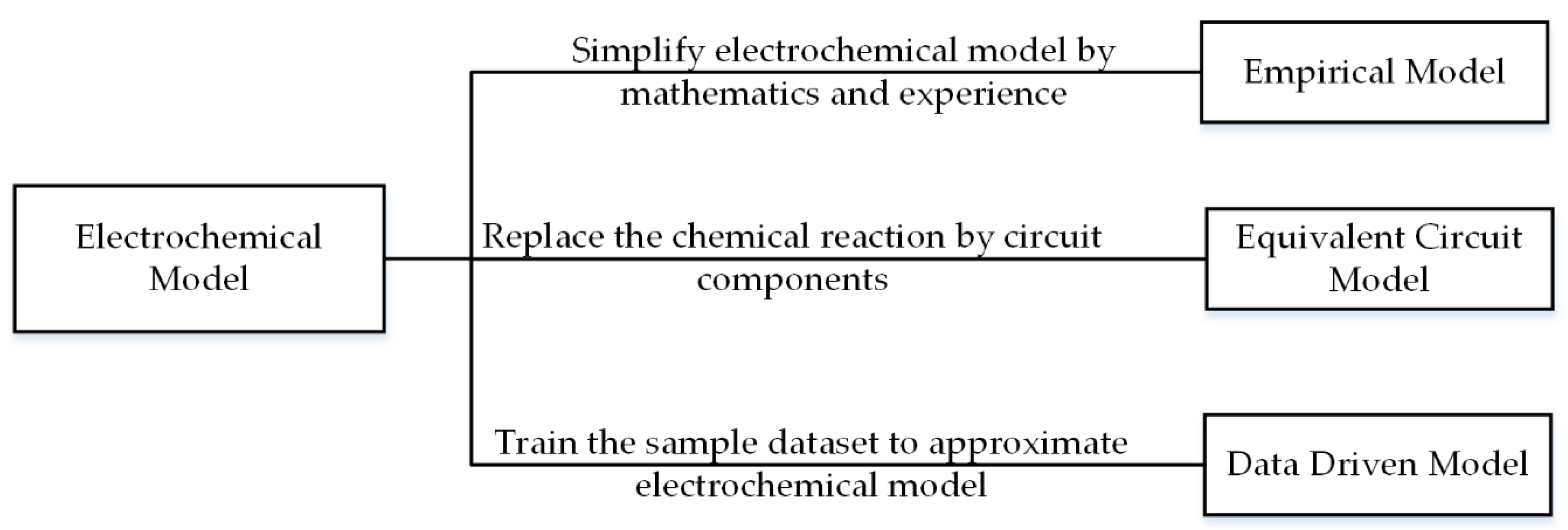
3. Discussion on the Battery Modeling Methods

The connections between the four modeling methods are discussed and the pros and cons of each method are listed in this section. Furthermore, the future trends in battery modeling methods are discussed.

3.1. Comparison of the Battery Modeling Methods

The modeling methods discussed in this paper are summarized in Figure 4. According to the description in the previous section, the pros and cons of the modeling methods are listed in Table 4.
Different battery modeling methods have some essential connections, as shown in Figure 5. Describing the specific reactions inside a battery in detail, the electrochemical model is the basis for the other models. The empirical model is known as a simplified electrochemical model. Circuit components in ECM are an alternative to chemical reactions in the electrochemical model. With the simple structure of ECM, the physical variables in ECM are easily explained and understood. Moreover, denoting the identical physical characteristics in a battery, some terms in the empirical model are equivalent to those in ECM [30]. The data-driven method directly describes the characteristics of the electrochemical model through data analysis.

3.2. Future Trends of Battery Modeling Methods

As previously described, the accuracy of the battery model is critical for the model-based SOC estimation methods. Hybrid models utilizing the advantages of each modeling technology are proposed for the purpose of improving the modeling accuracy. In [66], the Thevenin model represents the voltage corresponding to the current profile, while the nonlinear part of the model is represented by the Shepherd model. Likewise, the Nernst model can also replace the nonlinear OCV-SOC relationship of ECM for improving the modeling accuracy [67]. Since the kinetic battery model is capable of capturing the nonlinear capacity effects (such as the recovery effect and rate capacity effect), a hybrid battery model including ECM and a kinetic battery model is proposed for modeling batteries [68]. The electrochemical model can also be combined with the ECM by using the electrical analogy of the mass transport equations in electrodes and electrolytes [69]. In order to predict the variation of the parameters and the polarization voltage drop under the changing current, Butler–Volmer equation is simplified and added to the Thevenin model in [70].
ECM has been extensively applied to SOC estimation area but the relationship between the numbers of RC pairs and the accuracy of the ECM still needs further explanation. Several publications have tried to explain the relationship between the numbers of the RC networks and the accuracy of ECM [44,45,71,72]. However, the essential reason why some models are good for the specific battery is not fully known.
Once the structures of the battery model are determined, how to find the optimal parameters for each model is becoming important for the accuracy of the model. However, the importance of the parameters is not the same for the SOC estimation results. The updating frequency of each parameter does not need to be the same, since the parameters vary with different time scales. For example, the capacity decreases slowly with the lifespan of the battery, while the RC parameters change in the discharging process [22,73]. More work is still needed to find the key parameters in the battery models for SOC estimation and decide on a reasonable updating frequency for each parameter. Moreover, although temperature affects the performance of the Li-ion battery [74,75], the battery models for most SOC estimation methods have not taken temperature into consideration.

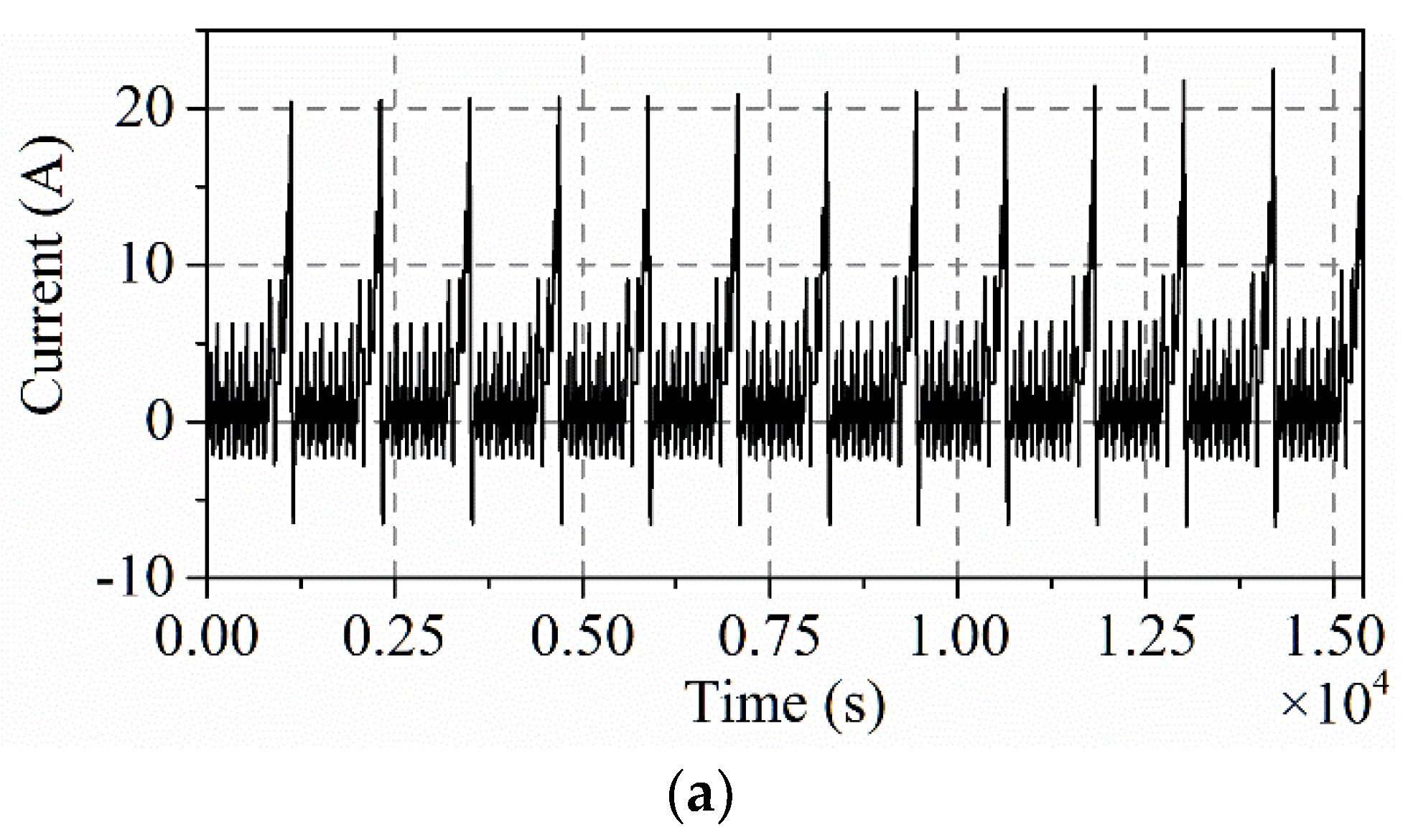
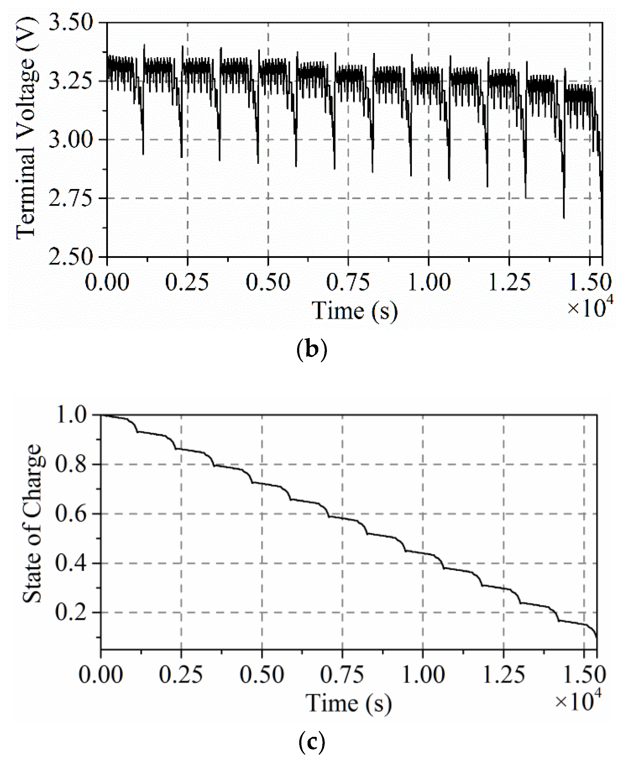
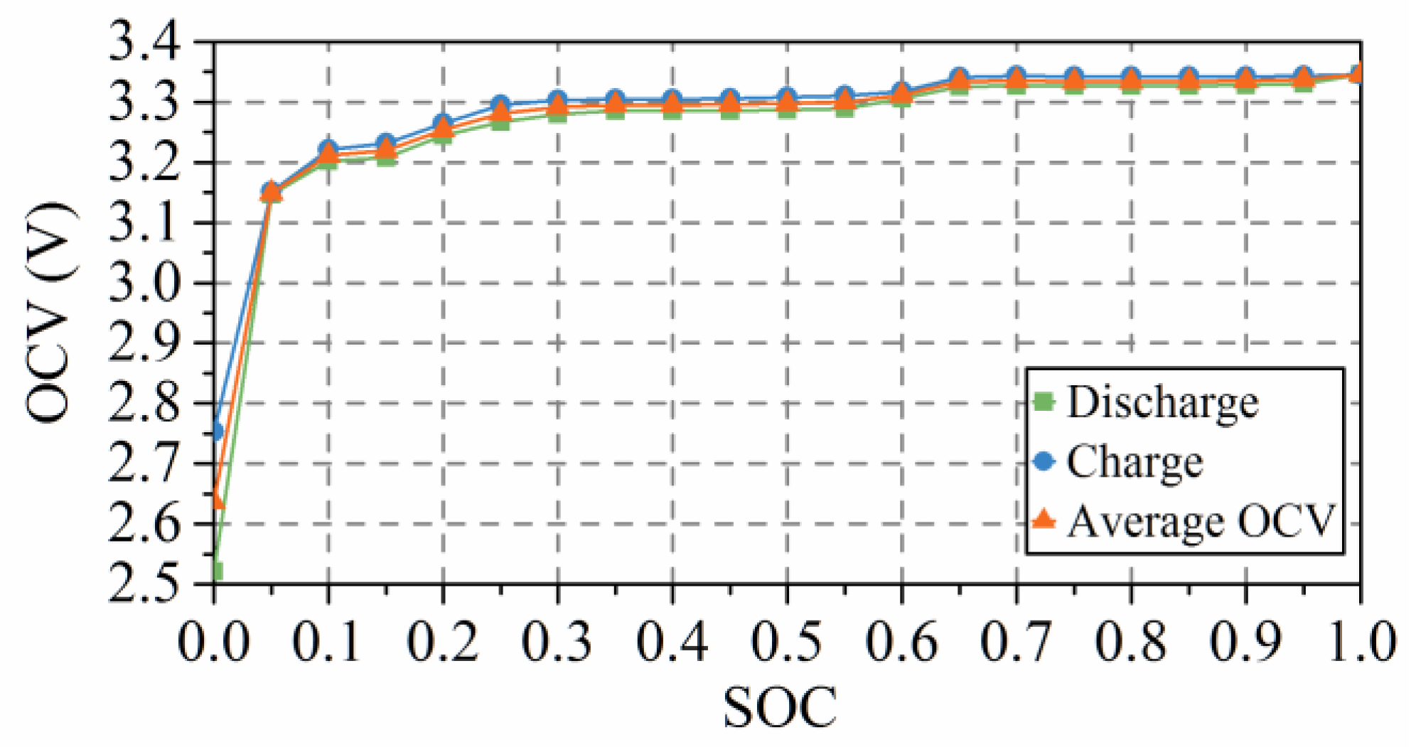
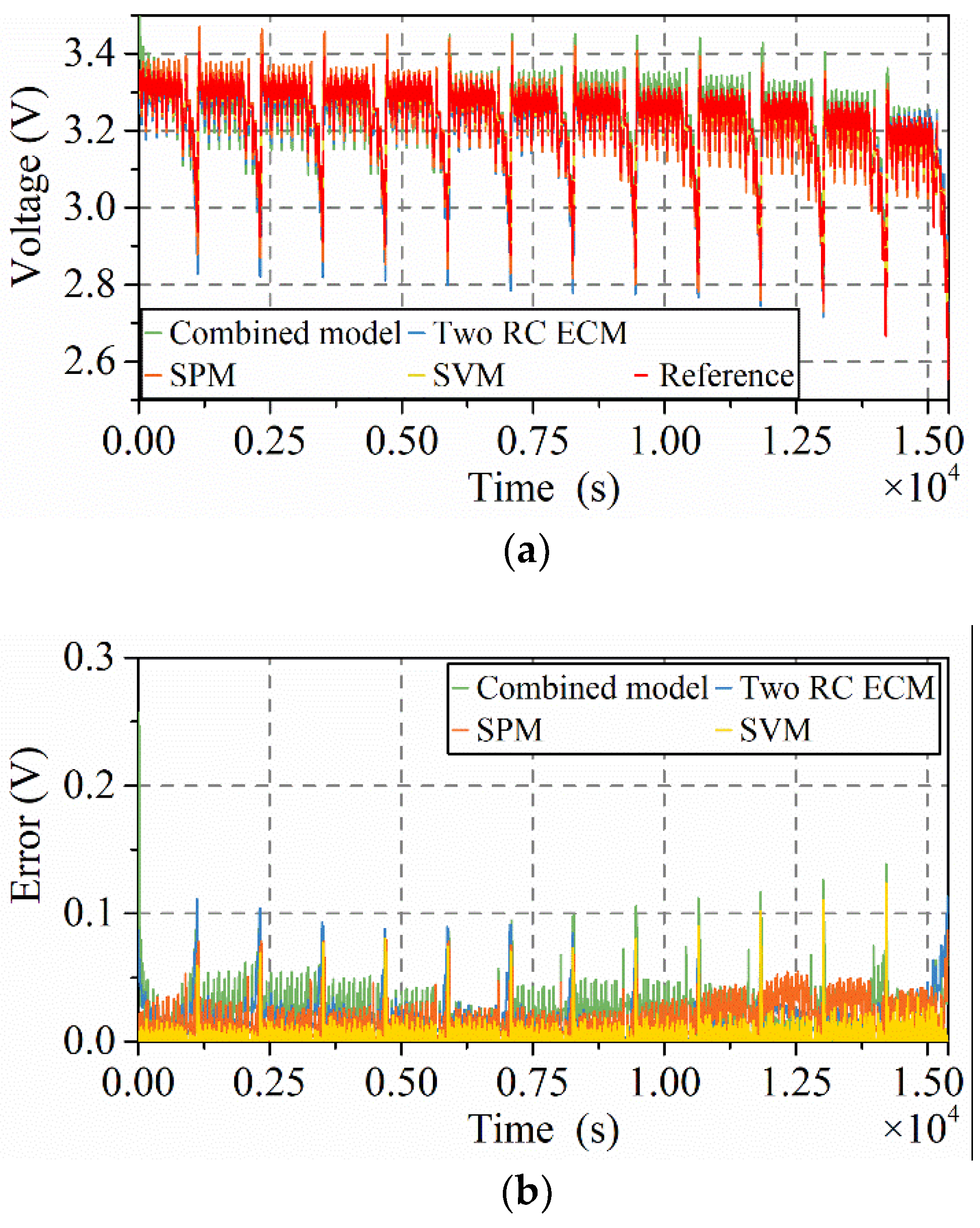
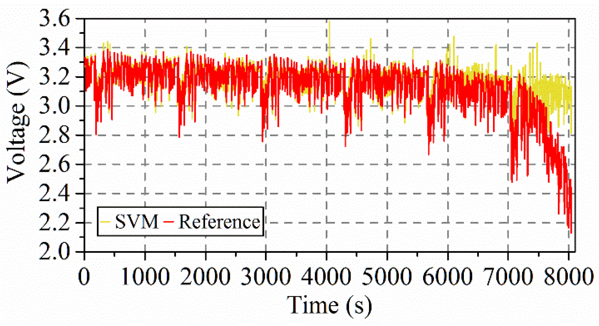
4. The Performance of the Four Typical Battery Models

In order to show the performance of the four typical modeling methods in more detail, the combined model [13], two RC ECM [10], SPM [14], and SVM battery models [15] are compared in terms of accuracy of voltage response and execution time in this section. For the details of each model, please refer to [10,13,14,15]. For fairness of comparison, GA [76] is used to optimize the parameters in the combined model, two RC ECM, and SPM. Our paper uses the MATLAB command ga to implement the parameters optimization by GA [77]. A LiFePO4 battery is discharged by NEDC profile in the MACCOR 4000 series test bench [10]. The nominal capacity of the battery is 10 Ah, and the nominal voltage is 3.2 V. The temperature in the test chamber is set to 25 °C and the sampling time is 1 s for data acquisition. The step time for the simulation of the models is also set to 1 s in this paper. In order to verify the four modeling methods, the LiFePO4 battery is discharging under multi-NEDC driving cycles. All the measurements from MACCOR are shown in Figure 6.
OCV is measured with 5% SOC interval after two hours’ battery relaxation time. Therefore, the two RC ECM can be built on the basis of the measurement in Figure 7.
With the constraint that the diminishing of OCV with the decrease of SOC, a high-order polynomial function represents the OCV-SOC relationship, as follows:
O C V = 330.2741 S O C 8 + 1507.8350 S O C 7 2869.7023 S O C 6 + 2949.8632 S O C 5 1773.9467 S O C 4 + 632.0383 S O C 3 128.9882 S O C 2 + 13.8940 S O C + 2.6371 .
Equation (3) further acts as the voltage source in the two RC ECM. The modeling results of the four modeling methods are shown in Figure 8 and Figure 9.
We can see that all the methods are able to predict the battery terminal voltage in Figure 8a. SVM and SPM achieve better results than the other two methods, as shown in Figure 9a, but the results of the two RC ECM and the combined model are also acceptable. The absolute error of the four methods (Figure 8b) proves that SVM obtains the best result of the four models, and the Mean Absolute Error (MAE) of SVM is 0.0034 V. The good accuracy of SVM is because the same data is used in SVM for training and testing. For further testing the SVM battery model, an Urban Dynamometer Driving Schedule (UDDS) [78] is applied to the SVM, trained by the measurement from NEDC. The results for the SVM battery model shown in Figure 10 are much worse than those in Figure 8. The MAE of the results in Figure 10 is 0.0632 V. Therefore, the accuracy is doubtful if another driving cycle different from the training samples is applied to the SVM battery model. The details of the absolute error in Figure 9b clearly show the performance of the four models in terms of accuracy of voltage prediction, while SPM shows comparable results to SVM. MAE and the execution time of the four models are listed in Table 5.
The MAE of SVM is much smaller than the others three models. Although GA is applied to optimize the parameters, it is still difficult to obtain true values for each parameter for SPM. Hence, the differences in MAE are not obvious for the SPM, the two RC ECM, and the combined model, since SPM contains as many as 28 parameters. The execution time in this paper is measured in MATLAB 2017b on a 64-bit computer with 2.30 GHz CPU, and the mean execution time of the battery model at each step is calculated in Table 5. It can be seen from Table 5 that the execution time of SVM is 0.0018 s, which is much longer than in the other models. An optimal model for the SOC estimation in real-time applications should include a good trade-off between accuracy and execution time. Therefore, considering the flaws of SPM and SVM, the combined model and ECM are still the first choice if their accuracy is acceptable for the specific application.

5. Conclusions

Considering the requirement in terms of robustness and accuracy for SOC estimation, model-based estimation has become popular for EV applications recently. By analyzing the structure of the model-based SOC estimation, it is found that the performance of SOC estimation is closely related to the accuracy of the battery model. This paper provides an extended review of the battery modeling methods. According to their features and theoretical foundations, the latest battery models are classified into four categories: empirical models, ECMs, electrochemical models, and data-driven models. On the basis of the electrochemical reactions inside the battery, the electrochemical models are the foundation of the other models. Empirical models are developed by using mathematical expressions to simplify the electrochemical model. The circuit components in ECM can be regarded as an alternative to the reactions in the electrochemical model. Moreover, the data-driven models can be seen as describing the performance of the electrochemical model through the data analysis of the training samples.
The features and connections of the modeling methods and their future trends have been discussed. Empirical models and ECMs are easier to be understood and have a higher computational efficiency. The accuracy of the data-driven model closely relies on the training dataset. Electrochemical models give deep insight into the mechanism of the battery. In order to develop high-fidelity battery models, hybrid modeling methods and the relationship between ECM and the number of RC networks still require further research. In addition, more attention should be paid to how to update the parameters in the battery model. Temperature plays a key role in battery characteristics, but most of the proposed model-based SOC estimators have still not taken temperature into consideration.
Four typical models are compared in terms of accuracy and execution time with the measurement data from a LiFePO4 battery. After optimizing the parameters in each model by GA, the four models obtain acceptable results. The most accurate SVM model obtains 0.0034 V in MAE and the execution time of the combined model is only 6.3649   ×   10 7 s (MATLAB 2017b, 64 bit, 2.30 GHz CPU). SVM and SPM obtain better results in terms of accuracy, but the execution time of SVM and SPM is also longer than for the other two models. However, considering the flaws of SVM and SPM, the combined model and ECM are recommended for a LiFePO4 battery if their accuracy is acceptable for a specific application. It should be noted that the conclusions obtained from the experimental results in this paper are only limited to the LiFePO4 battery, which has a flat OCV-SOC curve.

Author Contributions

Jinhao Meng and Guangzhao Luo wrote the paper; Maciej Swierczynski and Daniel-Ioan Stroe designed the experiments; Mattia Ricco and Remus Teodorescu helped with improving this paper.

Acknowledgments

This work was supported in part by the Key Program for International S&T Cooperation and Exchange Projects of Shaanxi Province (2017KW-ZD-05) and the Fundamental Research Funds for the Central Universities (3102017JC06004) and (3102017OQD029). Jinhao Meng would like to thank the China Scholarship Council for supporting his study in the Department of Energy Technology, Aalborg University.

Conflicts of Interest

The authors declare no conflict of interest.

References

  1. Scrosati, B.; Garche, J. Lithium batteries: Status, prospects and future. J. Power Sources 2010, 195, 2419–2430. [Google Scholar] [CrossRef]
  2. Capasso, C.; Veneri, O. Experimental analysis on the performance of lithium based batteries for road full electric and hybrid vehicles. Appl. Energy 2014, 136, 921–930. [Google Scholar] [CrossRef]
  3. Bilgin, B.; Magne, P.; Malysz, P.; Yang, Y.; Pantelic, V.; Preindl, M.; Korobkine, A.; Jiang, W.; Lawford, M.; Emadi, A. Making the Case for Electrified Transportation. IEEE Trans. Transp. Electrif. 2015, 1, 4–17. [Google Scholar] [CrossRef]
  4. Rahimi-Eichi, H.; Ojha, U.; Baronti, F.; Chow, M. Battery Management System: An Overview of Its Application in the Smart Grid and Electric Vehicles. IEEE Ind. Electron. Mag. 2013, 7, 4–16. [Google Scholar] [CrossRef]
  5. Castano, S.; Gauchia, L.; Voncila, E.; Sanz, J. Dynamical modeling procedure of a Li-ion battery pack suitable for real-time applications. Energy Convers. Manag. 2015, 92, 396–405. [Google Scholar] [CrossRef]
  6. Waag, W.; Fleischer, C.; Sauer, D.U. Critical review of the methods for monitoring of lithium-ion batteries in electric and hybrid vehicles. J. Power Sources 2014, 258, 321–339. [Google Scholar] [CrossRef]
  7. Kalawoun, J.; Biletska, K.; Suard, F.; Montaru, M. From a novel classification of the battery state of charge estimators toward a conception of an ideal one. J. Power Sources 2015, 279, 694–706. [Google Scholar] [CrossRef]
  8. Zhang, J.; Lee, J. A review on prognostics and health monitoring of Li-ion battery. J. Power Sources 2011, 196, 6007–6014. [Google Scholar] [CrossRef]
  9. Cuma, M.U.; Koroglu, T. A comprehensive review on estimation strategies used in hybrid and battery electric vehicles. Renew. Sustain. Energy Rev. 2015, 42, 517–531. [Google Scholar] [CrossRef]
  10. Meng, J.; Ricco, M.; Luo, G.; Swierczynski, M.; Stroe, D.I.; Stroe, A.-I.; Teodorescu, R. An Overview and Comparison of Online Implementable SOC Estimation Methods for Lithium-ion Battery. IEEE Trans. Ind. Appl. 2017. [Google Scholar] [CrossRef]
  11. Fotouhi, A.; Auger, D.J.; Propp, K.; Longo, S.; Wild, M. A review on electric vehicle battery modelling: From Lithium-ion toward Lithium-Sulphur. Renew. Sustain. Energy Rev. 2016, 56, 1008–1021. [Google Scholar] [CrossRef]
  12. Zhang, C.; Li, K.; McLoone, S.; Yang, Z. Battery modelling methods for electric vehicles—A review. In Proceedings of the 2014 European Control Conference, Strasbourg, France, 24–27 June 2014; pp. 2673–2678. [Google Scholar]
  13. Tang, X.; Wang, Y.; Chen, Z. A method for state-of-charge estimation of LiFePO4 batteries based on a dual-circuit state observer. J. Power Sources 2015, 296, 23–29. [Google Scholar] [CrossRef]
  14. Zhou, D.; Zhang, K.; Ravey, A.; Gao, F.; Miraoui, A. Online Estimation of Lithium Polymer Batteries State-of-Charge Using Particle Filter-Based Data Fusion With Multimodels Approach. IEEE Trans. Ind. Appl. 2016, 52, 2582–2595. [Google Scholar] [CrossRef]
  15. Meng, J.; Luo, G.; Gao, F. Lithium Polymer Battery State-of-Charge Estimation Based on Adaptive Unscented Kalman Filter and Support Vector Machine. IEEE Trans. Power Electron. 2016, 31, 2226–2238. [Google Scholar] [CrossRef]
  16. Jafari, M.; Gauchia, A.; Zhang, K.; Gauchia, L. Simulation and Analysis of the Effect of Real-World Driving Styles in an EV Battery Performance and Aging. IEEE Trans. Transp. Electrif. 2015, 1, 391–401. [Google Scholar] [CrossRef]
  17. Masrur, M.A.; Sutanto, D.; Tannahill, V.R.; Muttaqi, K.M. Future vision for reduction of range anxiety by using an improved state of charge estimation algorithm for electric vehicle batteries implemented with low-cost microcontrollers. IET Electr. Syst. Transp. 2015, 5, 24–32. [Google Scholar] [CrossRef]
  18. Dai, H.; Wei, X.; Sun, Z.; Wang, J.; Gu, W. Online cell SOC estimation of Li-ion battery packs using a dual time-scale Kalman filtering for EV applications. Appl. Energy 2012, 95, 227–237. [Google Scholar] [CrossRef]
  19. Partovibakhsh, M.; Liu, G. An adaptive unscented kalman filtering approach for online estimation of model parameters and state-of-charge of lithium-ion batteries for autonomous mobile robots. IEEE Trans. Control Syst. Technol. 2015, 23, 357–363. [Google Scholar] [CrossRef]
  20. Tian, Y.; Xia, B.; Sun, W.; Xu, Z.; Zheng, W. A modified model based state of charge estimation of power lithium-ion batteries using unscented Kalman filter. J. Power Sources 2014, 270, 619–626. [Google Scholar] [CrossRef]
  21. Xu, L.; Wang, J.; Chen, Q. Kalman filtering state of charge estimation for battery management system based on a stochastic fuzzy neural network battery model. Energy Convers. Manag. 2012, 53, 33–39. [Google Scholar] [CrossRef]
  22. Zhang, C.; Wang, L.Y.; Li, X.; Chen, W.; Yin, G.G.; Jiang, J. Robust and Adaptive Estimation of State of Charge for Lithium-Ion Batteries. IEEE Trans. Ind. Electron. 2015, 62, 4948–4957. [Google Scholar] [CrossRef]
  23. Hussein, A.A.H.; Batarseh, I. An overview of generic battery models. In Proceedings of the IEEE Power and Energy Society General Meeting, San Diego, CA, USA, 24–29 July 2011. [Google Scholar]
  24. Moore, S.; Eshani, M. An Empirically Based Electrosource Horizon Lead-Acid Battery Model. Int. Congr. Expos. 1996. [Google Scholar] [CrossRef]
  25. Manwell, J.; McGowan, J. Extension of the kinetic battery model for wind/hybrid power systems. Proc. EWEC 1994, 50, 284–289. [Google Scholar]
  26. Unnewehr, L.E.; Nasar, S.A. Electric Vehicle Technology; Wiley: Hoboken, NJ, USA, 1982; ISBN 047108378X. [Google Scholar]
  27. Fang, H.; Zhao, X.; Wang, Y.; Sahinoglu, Z.; Wada, T.; Hara, S.; De Callafon, R.A. State-of-Charge Estimation for Batteries: A Multi-model Approach. In Proceedings of the American Control Conference (ACC), Portland, OR, USA, 4–6 June 2014; pp. 2779–2785. [Google Scholar]
  28. Li, S.; Ke, B. Study of battery modeling using mathematical and circuit oriented approaches. In Proceedings of the IEEE Power and Energy Society General Meeting, San Diego, CA, USA, 24–29 July 2011. [Google Scholar]
  29. Tremblay, O.; Dessaint, L.-A.; Dekkiche, A.-I. A Generic Battery Model for the Dynamic Simulation of Hybrid Electric Vehicles. IEEE Veh. Power Propuls. Conf. 2007, 284–289. [Google Scholar] [CrossRef]
  30. Tremblay, O.; Dessaint, L.A. Experimental validation of a battery dynamic model for EV applications. World Electr. Veh. J. 2009, 3, 289–298. [Google Scholar]
  31. Seitl, C.; Kathan, J.; Lauss, G.; Lehfuss, F. Selection and implementation of a generic battery model for PHIL applications. IECON Proc. 2013, 5412–5417. [Google Scholar] [CrossRef]
  32. Seitl, C.; Kathan, J.; Lauss, G.; Lehfuss, F. Power hardware-in-The-loop implementation and verification of a real time capable battery model. IEEE Int. Symp. Ind. Electron. 2014, 2285–2290. [Google Scholar] [CrossRef]
  33. Plett, G.L. Extended Kalman filtering for battery management systems of LiPB-based HEV battery packs—Part 3. State and parameter estimation. J. Power Sources 2004, 134, 277–292. [Google Scholar] [CrossRef]
  34. Srinivasan, V.; Weidner, J.W.; Newman, J. Hysteresis during Cycling of Nickel Hydroxide Active Material. J. Electrochem. Soc. 2001, 148, A969. [Google Scholar] [CrossRef]
  35. Hu, X.; Sun, F.; Zou, Y.; Peng, H. Online estimation of an electric vehicle Lithium-Ion battery using recursive least squares with forgetting. Proc. Am. Control Conf. 2011, 935–940. [Google Scholar] [CrossRef]
  36. Plett, G. Battery Management Systems, Volume I:Battery Modeling; Artech House: Norwood, MA, USA, 2015; ISBN 163081024X. [Google Scholar]
  37. Hageman, S.C. Simple pspice models let you simulate common battery types. Electron. Des. News 1993, 38, 117–129. [Google Scholar]
  38. He, H.; Xiong, R.; Fan, J. Evaluation of Lithium-Ion Battery Equivalent Circuit Models for State of Charge Estimation by an Experimental Approach. Energies 2011, 4, 582–598. [Google Scholar] [CrossRef]
  39. Wu, B.; Chen, B. Study the performance of battery models for hybrid electric vehicles. In Proceedings of the 2014 IEEE/ASME 10th International Conference on Mechatronic and Embedded Systems and Applications (MESA), Senigallia, Italy, 10–12 September 2014; pp. 1–6. [Google Scholar]
  40. Rael, S.; Urbain, M.; Renaudineau, H. A mathematical lithium-ion battery model implemented in an electrical engineering simulation software. In Proceedings of the 2014 IEEE 23rd International Symposium on Industrial Electronics (ISIE), Istanbul, Turkey, 1–4 June 2014; pp. 1760–1765. [Google Scholar]
  41. Jin, F.; Yongling, H.; Guofu, W. Comparison study of equivalent circuit model of Li-ion battery for electrical vehicles. Res. J. Appl. Sci. Eng. Technol. 2013, 6, 3756–3759. [Google Scholar] [CrossRef]
  42. Fang, J.; Qiu, L.; Li, X. Comparative study of Thevenin model and GNL simplified model based on kalman filter in SOC estimation. Int. J. Adv. Res. Comput. Eng. Technol. 2017, 6, 1660–1663. [Google Scholar]
  43. Liu, C.; Liu, W.; Wang, L.; Hu, G.; Ma, L.; Ren, B. A new method of modeling and state of charge estimation of the battery. J. Power Sources 2016, 320, 1–12. [Google Scholar] [CrossRef]
  44. Hu, X.; Li, S.; Peng, H. A comparative study of equivalent circuit models for Li-ion batteries. J. Power Sources 2012, 198, 359–367. [Google Scholar] [CrossRef]
  45. Nejad, S.; Gladwin, D.T.; Stone, D.A. A systematic review of lumped-parameter equivalent circuit models for real-time estimation of lithium-ion battery states. J. Power Sources 2016, 316, 183–196. [Google Scholar] [CrossRef]
  46. Greenleaf, M.; Li, H.; Zheng, J.P. Modeling of LixFePO4 Cathode Li-Ion Batteries Using Linear Electrical Circuit Model. IEEE Trans. Sustain. Energy 2013, 4, 1065–1070. [Google Scholar] [CrossRef]
  47. Watrin, N.; Roche, R.; Ostermann, H.; Blunier, B.; Miraoui, A. Multiphysical lithium-based battery model for use in state-of-charge determination. IEEE Trans. Veh. Technol. 2012, 61, 3420–3429. [Google Scholar] [CrossRef]
  48. Forman, J.C.; Bashash, S.; Stein, J.L.; Fathy, H.K. Reduction of an Electrochemistry-Based Li-Ion Battery Model via Quasi-Linearization and Padé Approximation. J. Electrochem. Soc. 2011, 158, A93. [Google Scholar] [CrossRef]
  49. Fuller, T.F.; Doyle, M.; Newman, J. Relaxation Phenomena in Lithium-Ion-Insertion Cells. J. Electrochem. Soc. 1994, 141, 982. [Google Scholar] [CrossRef]
  50. Fuller, T.F.; Doyle, M.; Newman, J. Simulation and Optimization of the Dual Lithium Ion Insertion Cell. J. Electrochem. Soc. 1994, 141, 1. [Google Scholar] [CrossRef]
  51. Doyle, M.; Fuller, T.F.; Newman, J. Modeling of Galvanostatic Charge and Discharge of the Lithium/Polymer/Insertion Cell. J. Electrochem. Soc. 1993, 140, 1526. [Google Scholar] [CrossRef]
  52. Haran, B.S.; Popov, B.N.; White, R.E. Determination of the hydrogen diffusion coefficient in metal hydrides by impedance spectroscopy. J. Power Sources 1998, 75, 56–63. [Google Scholar] [CrossRef]
  53. Santhanagopalan, S.; Guo, Q.; Ramadass, P.; White, R.E. Review of models for predicting the cycling performance of lithium ion batteries. J. Power Sources 2006, 156, 620–628. [Google Scholar] [CrossRef]
  54. Fang, H.; Wang, Y.; Sahinoglu, Z.; Wada, T.; Hara, S. Adaptive estimation of state of charge for lithium-ion batteries. In Proceedings of the 2013 American Control Conference, Washington, DC, USA, 17–19 June 2013; pp. 3485–3491. [Google Scholar]
  55. Li, J.; Lotfi, N.; Landers, R.G.; Park, J. A Single Particle Model for Lithium-Ion Batteries with Electrolyte and Stress-Enhanced Diffusion Physics. J. Electrochem. Soc. 2017, 164, A874–A883. [Google Scholar] [CrossRef]
  56. Wang, Y.; Fang, H.; Sahinoglu, Z.; Wada, T.; Hara, S. Adaptive Estimation of the State of Charge for Lithium-Ion Batteries: Nonlinear Geometric Observer Approach. IEEE Trans. Control Syst. Technol. 2015, 23, 948–962. [Google Scholar] [CrossRef]
  57. Dey, S.; Ayalew, B.; Pisu, P. Nonlinear Robust Observers for State-of-Charge Estimation of Lithium-Ion Cells Based on a Reduced Electrochemical Model. IEEE Trans. Control Syst. Technol. 2015, 23, 1935–1942. [Google Scholar] [CrossRef]
  58. Yang, X.; Chen, L.; Xu, X.; Wang, W.; Xu, Q.; Lin, Y.; Zhou, Z. Parameter Identification of Electrochemical Model for Vehicular Lithium-Ion Battery Based on Particle Swarm Optimization. Energies 2017, 10, 1811. [Google Scholar] [CrossRef]
  59. Shen, W.-J.; Li, H.-X. Parameter identification for the electrochemical model of Li-ion battery. In Proceedings of the 2016 International Conference on System Science and Engineering (ICSSE), Puli, Taiwan, 7–9 July 2016; pp. 1–4. [Google Scholar]
  60. Zou, C.; Manzie, C.; Nesic, D. A Framework for Simplification of PDE-Based Lithium-Ion Battery Models. IEEE Trans. Control Syst. Technol. 2016, 24, 1594–1609. [Google Scholar] [CrossRef]
  61. Li, X.; Xiao, M.; Choe, S.-Y. Reduced order model (ROM) of a pouch type lithium polymer battery based on electrochemical thermal principles for real time applications. Electrochim. Acta 2013, 97, 66–78. [Google Scholar] [CrossRef]
  62. Klein, R.; Chaturvedi, N.A.; Christensen, J.; Ahmed, J.; Findeisen, R.; Kojic, A. Electrochemical Model Based Observer Design for a Lithium-Ion Battery. IEEE Trans. Control Syst. Technol. 2013, 21, 289–301. [Google Scholar] [CrossRef]
  63. Milocco, R.H.; Thomas, J.E.; Castro, B.E. Generic dynamic model of rechargeable batteries. J. Power Sources 2014, 246, 609–620. [Google Scholar] [CrossRef]
  64. Charkhgard, M.; Farrokhi, M. State-of-Charge Estimation for Lithium-Ion Batteries Using Neural Networks and EKF. IEEE Trans. Ind. Electron. 2010, 57, 4178–4187. [Google Scholar] [CrossRef]
  65. Du, J.; Liu, Z.; Wang, Y. State of charge estimation for Li-ion battery based on model from extreme learning machine. Control Eng. Pract. 2014, 26, 11–19. [Google Scholar] [CrossRef]
  66. Bae, K.C.; Choi, S.C.; Kim, J.H.; Won, C.Y.; Jung, Y.C. LiFePO4 dynamic battery modeling for battery simulator. In Proceedings of the IEEE International Conference on Industrial Technology, Busan, Korea, 26 February–1 March 2014; pp. 354–358. [Google Scholar]
  67. Xiong, R.; He, H.; Guo, H.; Ding, Y. Modeling for lithium-ion battery used in electric vehicles. Procedia Eng. 2011, 15, 2869–2874. [Google Scholar] [CrossRef]
  68. Kim, T.; Qiao, W. A hybrid battery model capable of capturing dynamic circuit characteristics and nonlinear capacity effects. IEEE Trans. Energy Convers. 2011, 26, 1172–1180. [Google Scholar] [CrossRef]
  69. Raël, S.; Hinaje, M. Using electrical analogy to describe mass and charge transport in lithium-ion batteries. J. Power Sources 2013, 222, 112–122. [Google Scholar] [CrossRef]
  70. Liu, S.; Jiang, J.; Shi, W.; Ma, Z.; Wang, L.Y.; Guo, H. Butler-Volmer-Equation-Based Electrical Model for High-Power Lithium Titanate Batteries Used in Electric Vehicles. IEEE Trans. Ind. Electron. 2015, 62, 7557–7568. [Google Scholar] [CrossRef]
  71. Einhorn, M.; Conte, F.V.; Kral, C.; Fleig, J. Comparison, selection, and parameterization of electrical battery models for automotive applications. IEEE Trans. Power Electron. 2013, 28, 1429–1437. [Google Scholar] [CrossRef]
  72. He, H.; Xiong, R.; Guo, H.; Li, S. Comparison study on the battery models used for the energy management of batteries in electric vehicles. Energy Convers. Manag. 2012, 64, 113–121. [Google Scholar] [CrossRef]
  73. Zhao, S.; Howey, D.A. Global Sensitivity Analysis of Battery Equivalent Circuit Model Parameters. In Proceedings of the 2016 IEEE Vehicle Power and Propulsion Conference (VPPC), Hangzhou, China, 17–20 October 2016; pp. 1–4. [Google Scholar]
  74. Jaguemont, J.; Boulon, L.; Dubé, Y. A comprehensive review of lithium-ion batteries used in hybrid and electric vehicles at cold temperatures. Appl. Energy 2016, 164, 99–114. [Google Scholar] [CrossRef]
  75. Zhang, C.; Li, K.; Deng, J.; Song, S. Improved Realtime State-of-Charge Estimation of LiFePO4 Battery Based on a Novel Thermoelectric Model. IEEE Trans. Ind. Electron. 2017, 64, 654–663. [Google Scholar] [CrossRef]
  76. Conn, A.R.; Gould, N.I.M.; Toint, P. A Globally Convergent Augmented Lagrangian Algorithm for Optimization with General Constraints and Simple Bounds. SIAM J. Numer. Anal. 1991, 28, 545–572. [Google Scholar] [CrossRef]
  77. Find Minimum of Function Using Genetic Algorithm—MATLAB ga—MathWorks Nordic. Available online: https://se.mathworks.com/help/releases/R2017b/gads/ga.html (accessed on 4 April 2018).
  78. EPA Urban Dynamometer Driving Schedule (UDDS). Available online: https://www.epa.gov/emission-standards-reference-guide/epa-urban-dynamometer-driving-schedule-udds (accessed on 4 October 2017).
Figure 1. Framework of the model-based State of Charge (SOC) estimation methods.
Applsci 08 00659 g001
Figure 2. Structure of the pseudo-2D (P2D) model and SPM. Reproduced from [55]. Copyright 2017, Electrochemical Society.
Applsci 08 00659 g002
Figure 3. The process of establishing the data-driven model.
Applsci 08 00659 g003
Figure 4. The classifications of battery modeling methods.
Applsci 08 00659 g004
Figure 5. The connections of different modeling methods.
Applsci 08 00659 g005
Figure 6. Measurement during multi-NEDC driving cycles. (a) Current; (b) voltage; (c) SOC.
Applsci 08 00659 g006aApplsci 08 00659 g006b
Figure 7. OCV measurement.
Applsci 08 00659 g007
Figure 8. Voltage prediction achieved by using the four models. (a) Voltage; (b) absolute error.
Applsci 08 00659 g008
Figure 9. Zoom of the voltage prediction achieved by using the four models (from 7221s to 8054 s): (a) Voltage; (b) absolute error.
Applsci 08 00659 g009
Figure 10. The performance of the SVM battery model in UDDS.
Applsci 08 00659 g010
Table 1. Typical empirical models.
Model TypeModel Equations
Shepherd model [24] y k = E 0 R i k K 1 z k
Unnewehr universal model [25,26] y k = E 0 R i k K 1 z k
Nernst model [27] y k = E 0 R i k K 2 ln ( z k ) + K 3 ln ( 1 z k )
Table 2. Modified empirical models.
ReferenceModel Expression
[29] y k = E 0 K Q Q i k T + A e B i k T
Q is the battery capacity, A is the exponential zone amplitude, B is the time constant inverse of the exponential zone, K is the polarization voltage.
[30]Discharge: y k = E 0 R i k K Q Q i k T ( i k T + i * ) + A e B i k T
Charge: y k = E 0 R i k K Q i k T 0.1 Q i * K Q Q i t i k T + A e B i k T
i* is the filtered current through the polarization resistance.
[31,32] y k = E 0 R i k R p o l i k * K Q ( 1 z k + z 0 1 ) + A e B ( 1 z k )
τ d i * d t + i * = i
R p o l = { K z k discharge K λ z k other   conditions
Rpol is the polarization resistance.
[27] y k = E 0 R i k K 2 ln ( τ 1 + z k ) + K 3 ln ( τ 2 + 1 z k )
τ 1 and τ 2 are the two additional constants.
[35] y k = E 0 R i k K 2 ln ( z k ) + K 3 ln ( 1 z k ) + s k M
s k = { 1 i k > ε 1 i k < ε s k 1 | i k | ε
ε is a small positive number, M is the correction term.
[33,36] y k = O C V ( z k ) + M 0 s k + M h k R i k
h k = e ( | η i k 1 γ T Q | ) h k 1 ( 1 e ( | η i k 1 γ T Q | ) ) M s i g n ( i k 1 )
s k = { s i g n ( i k ) i k > 0 s k 1 o t h e r w i s e
M and M0 are the parameters estimated from the test data.
Table 3. The expressions of the four common ECMs.
ModelExpression
Rint model [38]
Applsci 08 00659 i001
U t = U o c I R 0
Ut is the terminal voltage, Uoc indicates the OCV. I is the discharging current and Ro is the Ohm resistance.
Thevenin model [39,40]
Applsci 08 00659 i002
U t = U o c U 1 I R 0
R1 is the polarization resistance and C1 is the polarization capacitance, U1 is the voltage of the RC network.
PNGV model [41]
Applsci 08 00659 i003
U t = U o c U c a p U 1 I R 0
Ccap is the bulk capacitance.
GNL model [42]
Applsci 08 00659 i004
U t = U o c U c a p U 1 U 2 I R 0
R2, C2 are the concentration polarization resistance and capacitance.
Table 4. Pros and cons of the modeling methods.
Modeling MethodsEmpirical ModelEquivalent Circuit ModelElectrochemical ModelData-Driven Model
Modeling expression U t = f ( U o c , S O C , I ) U t = f ( U o c ( S O C ) , I , R , C ) U t = n f P D E s U t = f ( I , S O C , T )
ProsSimple expression, computational efficiencyEasily understood, widely used in SOC estimationHigh accuracy of voltage calculationHigh accuracy of voltage calculation, do not need prior knowledge of the battery
ConsLimited capability of describing the terminal voltageComplex parameter identification processRequire prior knowledge of the battery, time consumingLaborious training dataset collection process
Table 5. Comparison of the four models in MAE and execution time.
Model TypeMAE (V)Execution Time (s)
Combined model0.0212 6.3649   ×   10 7
Two RC ECM0.0184 9.6155   ×   10 7
SPM0.0159 2.2105   ×   10 5
SVM0.00340.0018

