Article

Multi-Objective and Multi-Rate Control of the Grinding and Classification Circuit with Electromagnetic Mill

Institute of Automatic Control, Silesian University of Technology, 44-100 Gliwice, Poland
*
Author to whom correspondence should be addressed.
Appl. Sci. 2018, 8(4), 506; https://doi.org/10.3390/app8040506
Submission received: 16 January 2018 / Revised: 22 February 2018 / Accepted: 22 March 2018 / Published: 27 March 2018

Abstract

:

Featured Application

Results reported in the paper were applied in semi-industrial grinding and classification circuits equipped with D100 and D200 electromagnetic mills and dedicated PLC and SCADA system. Modular and scalable control system as well as universal features of the electromagnetic mill allow for wide range industrial applications of the system including mineral processing, food, pharmaceutical industries and others.

Abstract

The paper presents an innovative construction and installation of dry grinding in electromagnetic mill that provides a significant reduction of energy consumption when compared to traditional mills. The installation constitutes complex multi-objective plant. To gain control over all the objectives, hierarchical structure of control system was developed where different time-horizons involve multi-rate scheme of steering. The paper presents solutions for the direct regulation, supervisory control, and optimization level. The electromagnetic mill installation constitutes a unique setup that causes open loop instability and implies the application of novel control schemes at all of the levels. The paper presents these solutions and illustrates them with the results of experiments carried out on the electromagnetic mill installations.

1. Introduction

Shredding of the raw material is a part of many technological processes, mostly concerning mineral materials, but chemical, food, and pharmaceutical industries are typical examples as well [1]. Usually grinding process is run by a mill where fed material is crushed with grinding media being put into motion. Construction of the mill, its size, and output depend on particular demands following from the application. In the most classical drum mills, grinding media of ball, cylpebs, or rod type, rotate in a cylindrical chamber. Conventional grinding is carried out by material removal by the grinding media [2]. Disadvantage of classical mills is a high energy consumption that leads to low efficiency due to the high loss of energy supplied to put the grinding media and the mill shell into motion [3,4]. Another problem concerns the control of the grain shape.
The installation of dry grinding in the electromagnetic mill offers ability to control grain size, flow of the grinding media, exact classification and recycle of oversized grains. Parameterization of the installation allows for influencing grain shape, moisture, temperature, area, and energy surface properties. An interesting comparison of sorption ability of mechanically and thermally activated sodium bicarbonate is presented in [5]. Three types of mills: fluid bed opposed jet mill, fine impact mill, and electromagnetic mill were compared. The electromagnetic mill, as the alternative to standard mills is presented in [6] where high-energy milling was used to obtain tetragonal form of PbO. Generally, the electromagnetic mill is used to achieve grinding efficiency increased even by 50%. Heat recovery system is used for drying and heating the material that increases milling capacity. All of the mentioned characteristics of the electromagnetic mill have not been developed yet enough deeply, and, in turn, not reported. Lack of the researches and huge potential of the electromagnetic mills is a serious motivation to undertake the challenges.
The paper presents the electromagnetic mill installation that is a unique solution. In the literature only, one other solution was presented in [7], namely an electromagnetic mill having inductor with hidden poles. The solution presented in this paper uses apparent poles and the physical structure of the mill is different. The most important novelty is vertically opposed pneumatic transport of grinding material which causes instability of the setup in an open loop. Thus, to meet the multi objective requirements, a set of control schemes has been developed in every level of control: direct regulation, supervisory control, and optimization so the system performs stably and robustly. Important challenge was involved by the states of the setup, which cannot be measured directly. The paper presents developed indirect measurement methods and data processing that is applied in the system.
All of the advantages of the electromagnetic mill can be achieved by a specially designed control system. It is shown in the paper that the installation is a complex multi-objective plant. To put all the objectives in an order, multi-rate control is proposed. Structure of the control system is then layered according to the time horizon of validity of control laws that are related to a certain set of objectives. Control theory calls such a structure hierarchical control. Hierarchically structured control system constitutes the only arrangement to manage multi-objective technological plant.
Section 2 of the paper is devoted to the description of grinding and classification circuit, which uses the electromagnetic mill. Three subsections focus on the main elements of the installation: the electromagnetic mill, pneumatic transporting system, and classifiers. Examples of the electromagnetic mill installations of different working chamber size are presented to explain the idea of vertically opposed pneumatic transport of grinding material, to express the multi-objective nature of the installation and to reflect necessity of multi-rate control approach.
Measurement system is presented in Section 3 with special attention devoted to indirect measurements that serve as an inherent property of the electromagnetic mill installation. There are indicated all quantities (signals) that are used by the control system, together with their assignment to the proper class: states, manipulated variables, and disturbances. Such the assignment creates structure of the system as the plant to be controlled. Special attention is payed to fulfilment level of the working chamber which is important unmeasurable plant state. Indirect measurement using acoustic signal registration and analysis is proposed to solve the problem. It is also described in Section 3 a novel indirect measurement of material flow using a vibration signal. An indirect (vision) method has been developed to measure the granulation of the product. In Section 3, indirect method of grinding media fulfillment in the working chamber is also presented. The method uses measurement of active power delivered to the electromagnetic mill by the inverter.
Section 4 presents control system with all the layers of hierarchical structure i.e., management, optimization, supervisory and direct control. Each element is illustrated with experiments being carried out on the electromagnetic mill installation. The working chamber fulfilment is described as an example of the most challenging control problem in the direct layer. Another direct control task is the regulation of the electromagnetic mill frequency. Supervisory level is illustrated with a specially designed control algorithm that balances the pneumatic transporting system. It is also shown in Section 4 the relation between management and optimization layers and the supervisory layer functionality. The multi-objective and multi-rate nature of the entire control system is well illustrated by this section. Special attention is devoted here to optimization layer. A novel algorithm which minimizes active power of the inverter subject to different constraints is presented.
The paper summarizes conclusion in Section 5, where further works are pointed out.

2. Grinding and Classification Circuit

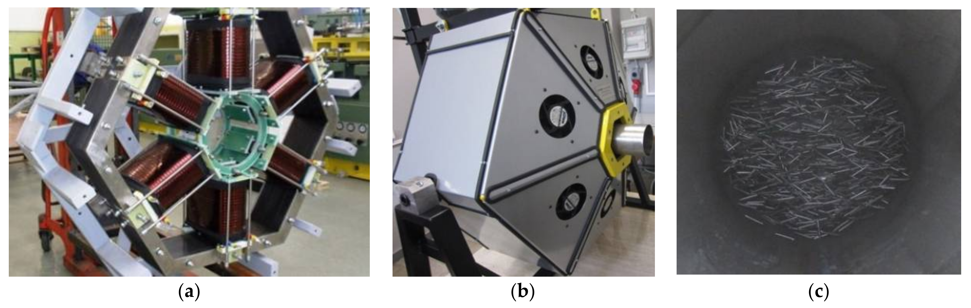
2.1. Electromagnetic Mill

Electromagnetic mill [8] puts grinding media into motion by electromagnetic field influence. Grinding media are the ferromagnetic particles in the form of small cylinders (about 10 mm of length and 1 mm of diameter). Six electromagnets (Figure 1a) surround a tube (Figure 1b) and create a working chamber where grinding media move chaotically (Figure 1c), due to impacts in rotating electromagnetic field. It can be seen in Figure 1b, that the unit can be set at an angle that allows for load flowing down. Adjustment of the angle is the simplest way to control grinding material flow [9]. Electromagnetic mill is a novel construction and it is applied in laboratories for research rather than in an industry. Potential advantages of the mill are huge if the circuit is properly constructed and parameterized with respect to material transport, product classification, and recycled. Such a system has been developed [10], intensively examined [11,12,13,14,15,16,17], and finally patented [18] by the consortium of Polish universities and companies: Silesian University of Technology, Gliwice (leader), AGH University of Science and Technology, Kraków (technology of milling), ELTRAF Company, Lubliniec (electromagnetic mill producer), and AMEplus Company, Gliwice (automation equipment). Appendix A gathers more details about the previous works in relation to the manuscript.
Figure 2a presents electromagnetic milling system with working chamber 100 mm of diameter that is installed in Silesian University of Technology (Laboratory of Institute of Automatic Control). Other installation was scaled up to 200 mm of the working chamber diameter (Figure 2b) and assembled in ELTRAF Company, where the system with 320 mm of the working chamber was developed as well (yoke of the electromagnets is presented in Figure 2c).
It can be seen in Figure 2a,b that the yokes of electromagnets are positioned horizontally, which means that the grinded material is transported vertically. Figure 3 presents the general scheme of the system. The counter-flow pneumatic transport of the processed material is applied. The blower generates under-pressure in the installation and causes air stream flow from the intake up to the outlet. Air flaps adjust respective streams.
The feed is loaded from the top by the screw feeder, trough so called preliminary classifier, while the transporting air stream is supplied from the bottom of the working chamber (main air stream). After being grinded, the grains are swept up to the preliminary classifier where the larger ones are taken back down into the working chamber. In this way inner recycle is formed. Lighter grains are swept up to the main classifier.
After fine classification provided by the main classifier, oversized grains go back to the working chamber (green dashed line in Figure 3), which forms an external recycle. The main classifier is additionally fed by the air stream (additional air stream) to adjust the separation process. Due to under-pressure in the entire circuit, a rotary valve is used in the recycle path to separate different pressures. The recycle stream is directed to the electromagnetic mill from the bottom side using third air stream (recycle air), which is adjusted by a separate flap.
Grains of desired size are transported from the main classifier into the cyclone that separates the material (final product stream) from the transporting air. Again, the rotary valve needs to be applied before the product is collected.
The presented grinding system is equipped with subsystems, which enhances its performance. Tube (working chamber) as well as the electromagnets of the electromagnetic mill warms up during operation and need cooling. System of cooling fans is then applied (see Figure 1b, fans are mounted in the cover). It may be noticed in Figure 1a that the output of the cooling fans is collected. Heat of the cooling air is used by the subsystem of heat recovery in order to warm the main air stream. The blower takes the fresh air from the outside and mixes it with warm air form the cooling system. Proper temperature and humidity of the main air stream would be needed to improve the milling process. Thus, another subsystem is applied: additional water may be injected into the main air stream (system of water fog injection) to increase the moisture content of the material in the chamber. Both, temperature and humidity of the transporting air changes influence the parameters of the milling process and affect the granularity of the final product.
Quality of grinding needs evaluation during operation, thus probing subsystem is used. Figure 4a presents a unit that automatically takes the probe of the product below the rotary valve. It can be seen in Figure 4a, diagonally mounted pneumatically supplied probe unit, which takes a sample from the product tube (right top corner in Figure 4a), according to schedule. Another subsystem allows for the automatic addition of the grinding media (Figure 4b). Specially designed feeder is activated when the mass of grinding media drops too much.

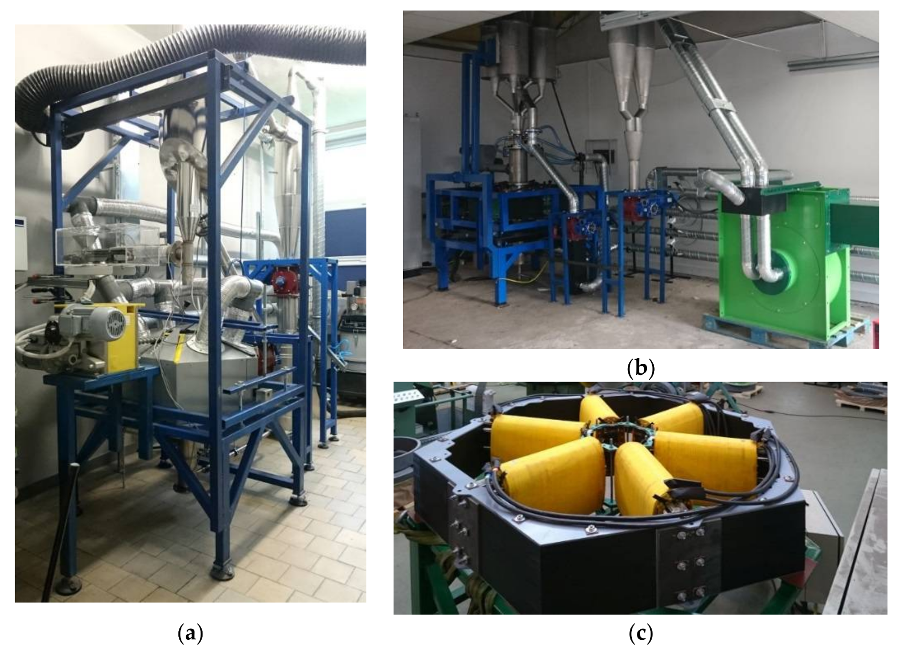
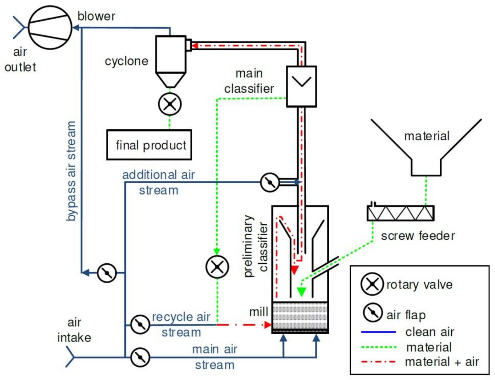
2.2. Pneumatic Transport System

Four transport air streams are use in the system. Respective air flows rate are controlled by the flaps and regulate the material flow in the installation. The main air stream is fed through the bottom of the electromagnetic mill and keeps the milled material at the desired amount in the working chamber. The recycle air stream forces the recycle material back to the working chamber of the mill. The additional air stream changes the linear velocity of the material entering the main classifier and allows for the separation process to be controlled. The bypass air stream allows additional control of the flow rate of the medium throughout the circuit. The most important property of the pneumatic transport system is its non-autonomy. It is not only impossible to adjust air flows in all four channels independently—these channels influence each other significantly.
The problem is much more complex if one analyses performance of units that create entire circle. The main air stream is responsible for the load of the working chamber and keeps the system stable: being too large deteriorates grinding process or even stops it by sweeping the entire load up; being to small deteriorates grinding as well, or even causes backfilling of the mill, which is the emergency state and causes the system emergency shutdown. The recycle air stream acts as a disturbance of the main air stream. Due to lack of the tank in the recycle path all the recycle flow produced by the main classifier needs to be turned back into the working chamber. The objectives of the main and recycle air streams are different. Even more distant objective concerns the additional air stream plugged to the main classifier. The main classifier is of the inertial type and determines selection between fine and coarse grain size. The input speed of the grains decides about average particle size.
Multi-objective role of the pneumatic transport system also concerns the number of parameters that influence the quality of the grinding. These parameters can be defined differently for various materials. Generally, they concern the acceleration of physical and chemical processes, facilitation of the transport and storage of the product, achieving the required properties of the chemical reaction or biological process product, etc. To achieve these requirements, not only grain size are taken into account, but also shape of the grain, its absorptivity, abrasion, the ability to create microstructures, and other physical properties. Analysing these requirements and building proper models make possible determining parameters of the pneumatic transport system as flow, temperature, or humidity [14,15]. These objectives define basic tasks of the management layer of the control system.

2.3. Classification and Recycles

Quality of grinding depends mostly on the classification. Too large grains need to be recycled and grinded again. This task is done in the electromagnetic mill circuit twice: in preliminary and main classifier. Ratio of the air stream that passes the working chamber to the feed inflow should be properly adjusted to let only larger grains fall down into the working chamber while smaller (and lighter) grains are swept upwards to the main classifier (there is no need to grind them). The main air stream keeps the load of the working chamber nearly constant and balances inflow of the larger grains with the outflow of grinded grains that are swept upwards in a similar way as lighter grains of the feed. This time, however, lighter (grinded) grains are not transported through the central pipe of the preliminary classifier, which is partially blocked by inflow of the fresh material, but rather through the outside as it is shown in Figure 3 by red dash-dotted line. Special construction of the preliminary classifier [19] allows for yet another classification: the path of grinded grains slows down their speed, which again allows for the larger grains fall down together with inflow of the fresh material. In this way, the internal recycle of the larger grains is formed. Only grains of smaller size are swept upwards to the main classifier. However, the first and preliminary classification and inner recycle provides only a partial barrier for the grains of the larger size. Thus, precise classification is applied.
The main classifier performs precise classification. The classifier is of the inertial type, which means that the cut-off grain size depends on the input speed of the grains (in the air stream). In order to adjust cut-off grain size, additional air stream into the main classifier is applied. A quality of classification using the inertial classifier follows from the shape of cumulated mass of input. Figure 5 presents an example of the cumulated mass curve of copper ore grinded by electromagnetic mill with working chamber of 200 mm diameter [20].
It is clear from Figure 5 that the longer the grinding time, the curve is more flat, which means that there is greater gap between lower and larger grain sizes. For example, the case of Ff = 0.077 Mg/h (orange line) shows that about 50% of grains are less than 0.1 mm of average size, while 40% of grains are greater than 1 mm. Only 10% of grains are between 0.1 and 1 mm. In the case of Ff = 0.154 Mg/h (grey line), 31 % of grains are less than 0.1 mm of average size and 45% of grains are greater than 1 mm. There are 24% of grains between 0.1 and 1 mm. The first case is much simpler to be tackled by the classifier. If the task is to separate grains less, then the 0.1 mm the air stream should be adjusted with a large margin (it is not relevant where the cut-off size is placed between 0.1 and 1 mm). On the other hand, the second case illustrates sensitivity of the classification process on air stream value. It should be noticed that the sensitivity depends on the cut-off size due to the cumulated mass curve is more corrugated between 0.1 and 1 mm of grain size in the second case. This property of the main classifier needs to be taken into account as the objective of the control system.
The recycle flow created by the main classifier is fed back to the working chamber. Average time of grinding is then extended and the quality of grinding is improved. The material is not stored in the recycle path. Thus, in a steady state inflow of the fresh material to be grinded needs to be equal to the product out-flow from the main classifier. This is one of the most important objectives of the control system.

3. Measured Parameters and Signal

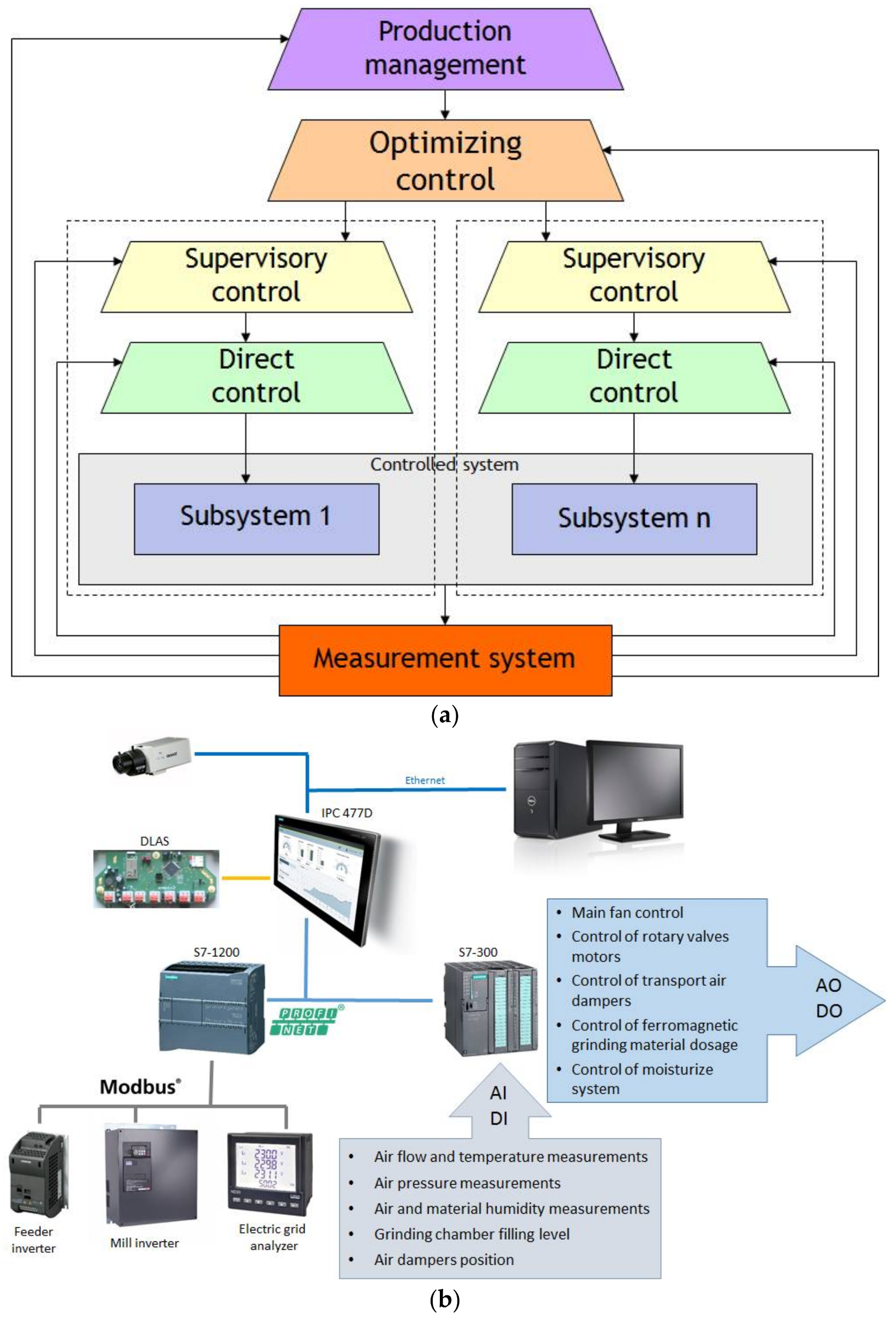
3.1. Structure of the Plant

The electromagnetic mill installation comprises a plant to be controlled with many control goals defined for each subsystem. The most important are parameters of the product concerning grain size, shape, physical, and chemical properties. To meet these requirements, every subsystem of the installation needs to perform properly in the nominal conditions, which means that after start-up procedures, a separate group of tasks arise and need to be performed by the control system.
Control of the ground material flow should be singled out. Vertical arrangement of the mill causes the control system of air streams fed to the mill system is designed to keep the ground material in the working chamber. A single pulling fan is a major source of the air flow, which is split into four coupled paths. Control system uses flaps to regulate the air flow. Pneumatic transport subsystem is then multi-input and multi-output plant, which realizes different objectives: the main air stream keeps ground material in the working chamber, recycle stream transports recycling material back to the working chamber, additional air stream parameterizes cut-off grain size of the main classifier. Any changes of one air stream causes changes in another two. If the objective in all of the paths would be the same then the control system could be designed similarly for all paths. Multi-objective case compels special design.
The pneumatic transport system is a dynamical plant what follows from significant volume of the coupled pipes and units. Therefore, pressure plays the crucial role in the control system design and serves as disturbance that needs compensation.
The final but not least structural element of the plant is energy management. There are two main energy consumers: the pulling fun and the electromagnetic mill. The first is not adjusted and can be dropped if control issues are concerned. The electromagnetic mill is supplied with three-phase current by an inverter generating set frequency. The electromagnets create a circulating field and grinding media exchange movement energy into crushing of the grains and produce heat. Part of this heat is taken away by the grinded material and transporting air stream. Another part is dissipated or recovered by cooling fans. Three aspects are met here: proper frequency of the rotating field, heat recovery, and mass of grinding media in the working chamber. The entire energy management system should take into account different objectives: to keep required output and quality spending as little energy as possible (optimization task); use additional subsystems to save or recover energy (design task); and, keep proper ratio of grinding media mass in the working chamber to set flow of the material (control system goal).
The structure of the plan can be illustrated by a set of signals that influences plant states. Figure 6 presents general structure of the circuit as a controlled system.
All three transporting air flows: main (Fg), recycle (Fr), and additional (Fd) are enforced by the blower (compare Figure 3). All of the streams are set by their own flaps. Changes of the position of one flap influence the flow ratio of all streams in the circuit and the output air stream parameters (flow—Fo, temperature—TIo, and pressure—PIo). It also influences the solids flow (Wp), fulfilment level (LI), and product temperature (TI). Finally, the most important influence concerns the product quality (QI). The circuit reacts similarly on the fresh feed flow changes (Fn), rotating electromagnetic field frequency changes (ω), and volume of the mass flow of the grinding media inserted into the working chamber (Fm). For the control system design purposes, all of the measurable signals were divided into three groups: control signals, disturbances, and system outputs (states). Besides those already described, the signals that are denoted in the structure are: Ew—ratio of volumetric flow of collected air from the cooling fans to taken air volumetric flow, Fh—volumetric flow of water mist to feed, control voltage, Hg—humidity of the taken air streams, Hd—humidity of air collected from the cooling fans, Hn—fresh feed humidity, Tg, Tr, Td—main, recycle, and additional air streams temperature, respectively, Pg, Pr, Pd—main, recycle, and additional air streams pressure, respectively, Ef—active power of the inverter.
Authors distinguish two types of inputs presented in Figure 6: control signals (left-side inputs) and disturbances (top-side inputs). A role of a certain input signal follows from the control system structure. Different objectives which need to be met by the control system impose the introduction of multi-rate control scheme. Multi-rate control arises in time domain and follows from different control horizon that is related to the certain control objective. Thus, hierarchical structure of the control system is formed (Section 4).
Some signals are not presented in Figure 6. These quantities are not used directly when the control system operates. However, they were measured and analysed at different stages of research to determine static and dynamical models that have been used in control, optimization, or fault detection algorithms design. An example is the distribution of magnetic field strength in the working chamber as a function of basic and output frequency set on the inverter (see Section 4.4). Model of the distribution serves as a constraint of energy optimization.

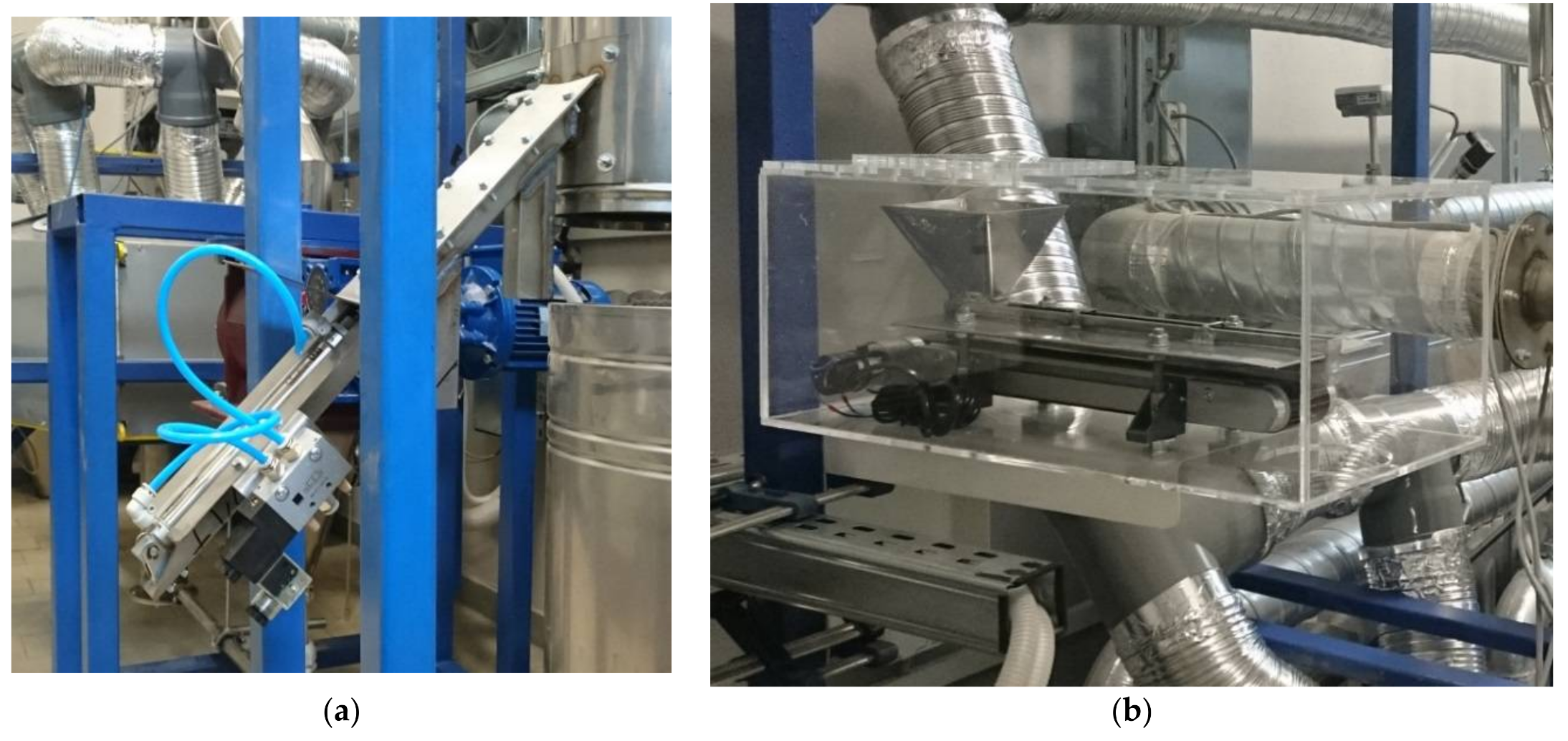
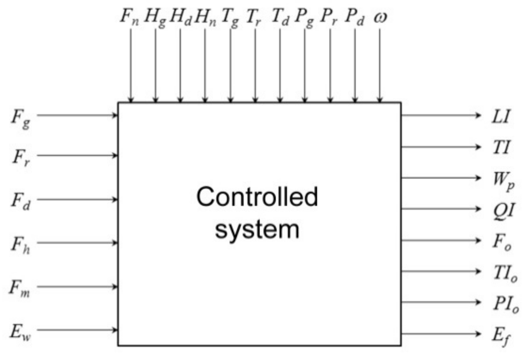
3.2. Direct and Indirect Measurements

Part of the signals described in the previous section can be measured directly. All of the temperatures and pressures are measured directly, as well as air flow, weight of the material and grinding media, frequency, and active power of the inverter. Measurement of the rest signals is either impossible or too expensive to be applied. In such a case indirect way is used.
From the control point of view the most important is fulfilment level of the working chamber (LI). This signal determines average grinding time and feeds fulfilment controller which stabilize the entire circuit. Extremely harsh and destructive environment in the working chamber does not allow for direct measurement. Several ideas of indirect measurement were tested as e.g., active power measurement with grinding media compensation or air pressure. The final solution bases on acoustic signal measurement [10]. A measurement microphone (Bayerdynamic, Heilbronn, Germany) is installed at the bottom of the preliminary classifier i.e., on the top of working chamber. Measured signal is preliminary tuned during empty mill runoff using information about the mill frequency and mass of the grinding media in the working chamber [21]. Figure 7 presents exemplary data of the acoustic measurement. Figure 7 presents changes of the signal amplitude (upper part) and frequency (bottom part) in the time period of 39 s. The mill operated in a steady frequency. Starting form 15 s, the working chamber was gradually filled with the material. One can notice in Figure 7 the decrease of the signal amplitude (upper part), as well as changes in the signal spectrogram in the frequency range of 6.2–6.6 kHz (marked on Figure 7 bottom part by dashed lines). The power of the measured signal in the given frequency range is presented on spectrogram in Figure 7 by colours: magenta-red-yellow reflecting low-moderate-high power values, respectively. Specific values are not important at this point, while normalization is introduced at later stages of signal processing. Amplitude characteristic is sensitive to disturbances, but the spectrogram characterizes significant robustness, thus the indirect measurement of the working chamber fulfilment bases on the spectrogram.
The working chamber can be understood as a tank with inflow and outflow. In order to keep constant level of the tank, inflow and outflow need to be equal. As air flow can be easily measured in a direct way, flow of the solid particles is very difficult to be measured. Although market offers robust sensors but they need long enough path to form measured stream uniformly (this is the case of air stream measurement in the electromagnetic mill system). Recycle path of the material form the main classifier to put back into the working chamber servers as an example of where such conditions are not provided. In this case, the vibration signal is measured as indirect flow measurement [11]. This method is contactless; the sensors (accelerometers) are small, not expensive, easy to use, and non-invasive to existing installation. Accelerometers (PCB, Depew, NY, USA) were mounted on the transporting pipes. Figure 8 presents an example of waveforms acquired for fine and coarse grains transported with two flows (fast and slow).
After extraction, noise reduction, and smoothing, it becomes possible to recognize flow and granulation of the load. Figure 9a presents example of power spectral densities (PSD) that were obtained for exemplary flow and different grain size, which was measured in one (Z) three axis of the accelerometer. These characteristics can be recalculated into specially defined energy index [12], which recognizes flow. Figure 9b presents energy index for different grain sizes. Several trails have been tested for two flows: fast (red lines) and slow (blue lines). Averaged result (solid line) is located between two dotted lines which represent lowest and highest result of the tests. Similarly to the measurement of working chamber fulfilment, indirect measurement of the solid particles in air transporting system bases on the energy index.
Despite that the vibration method can indirectly measure granulation (see Figure 9a), its resolution and disturbances sensitivity much reduces its applicability. Interesting trial was undertaken in [14] where presence of water in the material was used to evaluate its granulation. The grinding process in the electromagnetic mill is carried out on dry material. Significant improvement the product quality and efficiency of the milling process can be achieved by appropriate control of the moisture content of the grinded material. A model describing the changes of moisture content of bulk material in the installation of the electromagnetic mill has been developed. This model allows for the evaluation relation of the drying process in the path of material classification and its separation from the transport air, which significantly depends on granulation.
The most promising method of indirect granulation measurement is described in [16], where a novel method for grain size determination using real-time digital images processing is proposed. The method uses a probe (sampling) unit mounted on the product path (see Figure 4a). Vision camera (FLIR, Wilsonville, OR, USA) with lightning mounted at two specially determined angles is used to pick up the image. Detection of the grains bases on an adaptive segmentation algorithm, improved with distance transform to enhance grains detection. Figure 10 presents five stages of image processing. Each localized grain in the final image is parameterized with 11 factors: centre of mass X, centre of mass Y, perimeter, max ferret diameter, waddle disk diameter, area, orientation, Elongation factor, compactness factor, Heywood factor, and type factor. The set of parameters that were established for a certain probe can be used in a few scenarios. Firstly, as a tracking algorithm of assumed one granularity i.e., particle size. In this case, the algorithm acquires images with constant frequency and as result of processing each time, it produces a percent of particles in the sample with assumed granularity. Secondly, as a typical distribution of the particle sizes classes for one taken sample. The most important part in this case are the changes in time between next succeeding distributions. Thirdly, the method recognizes problem of milling media reduction, which may be observed in the Heywood factor value and area.
These two parameters are not the only which point out the necessity of grinding media supplement (the grinding media are constantly wear out during operation). If the image processing concludes the necessity of the grinding media supplement, then it would be necessary to confirm such a conclusion because there is no possibility to reduce the mass of the grinding media in the working chamber during operation. On the other hand, there is no way to measure the mass of the grinding media directly. Dependence of active power consumed by electromagnets on mass of the grinding media inside the working chamber makes indirect measurement possible [13,20]. Figure 11 presents respective results.

4. Structure of the Control System

4.1. General Multilayered Structure

The above presentation shows that from the control point of view the electromagnetic mill installation is a complex multi-input and multi-output plant, which should meet different objectives. These objectives need control system intervention in diversified moments of time that depends on different dynamics of the system elements. Thus multi-rate control schemes should be applied. Multi-rate control follows from different control horizon that is related to the certain control objective and creates a hierarchical structure of the control system, as shown in Figure 12a. Multi-rate control is realized using suitable hardware and communication nets, which is presented in Figure 12b [8]. For each of the subsystem presented in Figure 12a, specific objectives are formulated.
Production and management system is responsible for determination of the installation output according to specific parameters of the feed. It also determines the parameters of the product quality as product granulation, its humidity and temperature, and other physical and chemical properties, if necessary. Other parameters, which are determined in management layer, are: average time of grinding, type, and mass of grinding media in the working chamber (including possible range), cut-off grain size for main classifier, and limit values (including hysteresis) of the plant states for safety and fault detection subsystems. Both of these subsystems are the part of management layer because they are responsible for emergency stops of the system. To carry out this task, the respective measurements of the plant states need to be passed to the management layer, which is presented in Figure 12a. The example of task realized by fault detection system is presented in Section 4.2.
All of the objectives that are related to the management system are realized with the longest horizon when compared with other layers. Granulation and other parameters of the product are measured (usually using indirect way—see Section 3.2) relatively rarely when compared with other layers. The only exception is safety and fault detection subsystems, which reacts immediately and needs continuous measurement. Assignment these function to management layer does not destroy order of the layer where lower position means a shorter horizon of control: reaction of safety and fault detection subsystems depends on the plant specific state and can never happen (infinite horizon).
Optimization layer is fed with parameters that are determined by the management layer. The main role of optimization layer is to keep requirements concerning the production using a minimal amount of energy. This mostly relates to electromagnetic mill supply and heat recovery subsystem.
Supervisory control layer determines the set-points of the controllers that operate in the direct control. The entire system is inter-correlated which causes big troubles in dynamic control of the plant states. Thus, the supervisory controllers decrease the dynamic of the inter-correlated variables and make the direct control simpler.

4.2. Chosen Aspects of the Direct Control

Functional structure of the direct control is designed according to the leading variable which is inlet of the raw material to be grinded (the inlet flow is determined by management layer). Main task of the direct layer control is disturbances counteracting. Figure 13 presents example of functional structure of control systems in the direct layer namely the working chamber fulfilment control. Leading variable is inlet of the ground material, and thus the fulfilment level (measured indirectly as LI) is controlled by transporting air stream from the bottom side of the working chamber. The structure is of cascade type. Inner loop (FC) controls the air flow with the set point put out by the outer level control (LC). Leading variable stands for disturbances of the outer loop (slow disturbances), while changes of the air flow (fast disturbances) are regulated by the inner loop, which is the standard motivation for cascade structure application. To improve the inner loop performance, additional pressure compensation (PT) is applied. To improve the outer loop response, additional compensation (ET) of power supply of the electromagnetic mill is applied (slow disturbances as well). The crucial role in the presented structure plays the flow controller FC. As mentioned in the previous sections, pneumatic transporting system is strongly inter-correlated. It can be seen in Figure 13 that changes of the air flow/pressure in the recycle path change immediately LI, which in turns, involves the reaction of the controller LC and FC. As the consequence, one obtains changes in air flow/pressure in the recycle. Controller FC needs proper tuning. It is shown that the modelling of control path can significantly improve tuning. The most important, however, seems intervention of the supervisory control layer, which influences controllers set-points WN (see Section 4.3).
Figure 14a [10] presents example of control system response (LI). The auger feeder frequency was changed in the range 20 to 60 Hz, according to the management layer statement. The mill frequency was set to 30 Hz. Mass of the grinding media was 600 g. The experiment was carried out on the mill of 200 mm diameter. All of the above parameters have been established for copper ore of granulation 1–2 mm. The main air stream was controlled with the set point LISP = 3.5 (the value of LI is out of the unit and in this case may be positioned in the range 1–10). In this experiment, the working chamber was empty at the beginning. It can be seen how the system reaches a steady state while the working chamber if filled. In the experiment No. 1, at 90 s the feeder was switched off. In the experiment No. 2, the feeder was switched off at 65 s. In both of the experiments, the frequency of the feeder was increased linearly from 20 Hz up to 60 Hz starting from 20 s up to 50 s. It can be seen in Figure 14a that the measured signal did not drop below value 3, even for maximal mill throughput when auger feeder was operating at 60 Hz.
Figure 14b illustrates the performance of the inner loop of the control system that is presented in Figure 13. Red line represents the output signal that is generated by the controller FC. As can be seen, flap position (blue line) follows the control signal almost perfectly. It results in air flow value represented with black line. Note nonlinearity of static behaviour of the actuator (flap), which causes special attention when the controller is tuned.
Another example of direct control is the frequency of the electromagnetic mill. The actuator is the inverter. Figure 15 presents an example of control system response. As can be seen, set point is followed almost perfectly. The only drawback is delay. It results from specific communication with the inverter. In fact, the inverter is equipped with its own in-built controller, which causes delay. However, in such a perfect following simple prediction can improve the response (delay is constant).
In Figure 15, active power of the electromagnetic mill is also depicted. This signal is of a great importance if optimization issues are concerned (Section 4.4).

4.3. Supervisory Control

One of the most important objectives that is realized by the supervisory control layer is the balancing of the pneumatic transporting system. The problem follows from the fact, that air stream which transports solid particles is not measured. Moreover, flows that should be controlled are not the same as inlet streams, which can be measured in a simple way. The stream trough the working chamber is a composition of the main air stream and recycle stream. The stream trough the main classifier is the composition of both mentioned streams and the additional air stream. All of these streams are filled with solid particles. In order to estimate these unknown streams, the respective models have been identified [13]. Figure 16a presents an example of data and Figure 16b presents a set of identified models of the working chamber stream. Similar models have been identified for inflow to the main classifier and recycle.
Upper control layers (management and optimization) determines the operating points for the installation, which results in the set-points of the streams (flows) through the working chamber, main classifier and recycle. However, not all the possible values of these set points are reachable by the system only by changing the flap position before the air streams are mixed. These constraints not only follow from restricted flap positions, but also from cross-relations between flap positions and air flows. Thus, the task of the supervisory control algorithm is to check whether the three required values are reachable. If they are not, then the closest are taken. Special algorithm that checks the constraints and searches for the solution was developed and presented in [13]. It performs in two steps. Firstly, inflow to the main classifier and stream trough the working chamber is checked. The solution gives positions of the flaps in the main air stream and recycle. Then, all three flaps (main, recycle, and additional) are adjusted in order to meet the requirements concerning recycle stream. Such a construction of searching algorithm follows from the importance of streams: the least important is recycle, which only supports the shifting of the recycling material back into the working chamber without the responsibility of its parameterization.
Other tasks of the supervisory layer refer to data fusion. The most important measurement concerns the granulation of the product. Granulation measurement is mainly realized in the management layer using vision methods (indirect granulation measurement). This measurement is realized periodically and the period depends on the certain properties of grinded material. The period is significantly longer than control system reaction time in the lower layers. Thus, if the deviation of the granulation is small or changes are enough slow, then the re-parameterization of the lower layers is possible. However, in a case of violent disturbances, information concerning granulation change should be obtained faster in the system. As mentioned in the previous sections, there are two additional indirect measurements of the granulation, which are tested for electromagnetic mill: vibrational and moisture-based. Both are relative and give proper information about changes, rather than providing accurate measurement. The idea is to combine three of the used methods. Vision based method gives the reference and periodically feeds both supervisory algorithms of indirect granulation measurement in order to tune them. In this way, properly calibrated indirect granulation measurements can do the job much better before the next probe is processed by the vision method.
The similar task performs supervisory algorithm that controls the moisture of the product with respect to the ground material humidity in the context of the final granulation. Yet again, the horizon of the task places this algorithm in the supervisory layer because the reaction of granulation on changes in grinding material humidity is much slower than the humidity control that is realized in the direct layer [14].

4.4. Optimization

The electromagnetic grinding is a complex process, thus the formulation of the optimization problem is done in a top-down manner. To do so, the parameters that influence product quality and serves as the decision variables are specially selected [20]. Number of parameters were analysed: inverter frequencies (output frequency and basic frequency), parameters of the feed (volumetric flow, density, humidity, temperature, granulation), parameters of the air volumetric flow through the grinding chamber (total air volumetric flow through the grinding chamber, temperature of the air flow, humidity), parameters of the recycle flow (recycle air volumetric flow, recycle grinded material mass flow, granulation parameters of the recycle), and parameters of the grinding medium (mass, parameters as size, type of the ferromagnetic material etc.). Analysis shown in [20] proved that the most important impact on installation running costs is active power supplying the electromagnetic mill. On the other hand, output and primarily basic frequencies of the inverter shapes active power.
It is assumed in the optimization task that the parameters of the feed, air stream through the working chamber, parameters of the recycle and grinding media are constant and are not necessarily given if optimization is concerned because all of them are hidden in the cumulated mass curve that gives rise the constraints: chosen points of the curve need to fit the assumed range. In this way, an optimization task is formulated with criterion function (active power), constraints (points of the granulation curve), and decision variables (output and basic frequency of the inverter).
Figure 17a presents a model of the relation between active power and two mentioned frequencies. Despite that the active power may reach very small values, some regions of the characteristic presented in Figure 17a cannot be reached. Further research [22] extended conclusion [20], with additional constraints. Figure 17b presents the distribution of the magnetic induction inside the working chamber (the electromagnetic mill of 100 mm diameter, but with a removed transporting pipe to measure the magnetic induction in a wider distance) as a function of the output frequency. Similar result is obtained for the basic frequency. It is obvious that both of the frequencies need to be narrowed down to a range around standard 50 Hz to keep the induction larger than the lowest feasible. But, the problem is deeper and concerns the current that supplies the coils. To keep induction in a given range, two inequalities need to be fulfilled: ω o a l ω b b l ,   ω o a p ω b b p where ωo, ωb are output and basic frequencies and al, bl, ap, bp are parameters following from assumed feasible induction. Another constraint follows from a safety reason: the output frequency always needs be to less than the basic frequency with known extend due to a possible breakdown of the coils.
Figure 18a presents all of the constraints that pick up the feasible region that is presented in Figure 18b. Dedicated searching algorithm has been developed to find the minimum of the active power with respect to the constraints. Algorithm bases on establishing active constraints and unidimensional searching using golden section method [22].
The optimization algorithm has been tested on 100 mm diameter electromagnetic mill installation. Exemplary results are presented in Figure 19. The first experiment was carried out with no grinding media in the working chamber. With the period of 5 min, the desired magnetic induction was increased by 5 mT starting with 100 mT. As can be seen in Figure 19a in the first period, both of the frequencies were equal. Active power was reducing until the stop criterion of the golden section algorithm was met. After required induction increased, another active constraint was found, which resulted in different values of the frequencies (second period). Moreover, the output frequency reached its limit as well in this period. The next period brought a limit for the basic frequency; still the active power has been reduced. This, however, changed in the last period of the experiment: the required induction was too high and yet another constraint became active. Figure 19b presents similar experiments with the working chamber filled with 100, 150, 200, and 250 g of the grinding medium. One needs to realize that the model as in Figure 17a was obtained for the concrete mass of the grinding media. Thus, in each experiment presented in Figure 19, the model was different.

5. Conclusions

The electromagnetic mill is a novel construction that delivers a number of exiting control problems. On the other hand, the complexity of the installation that was designed to reach challenging demands placing the electromagnetic mill ahead of the competition needs extraordinary approach. In this paper, all of the objectives of the control system has been systematized to create hierarchical control structure where a multi-rate scheme of mutual connection between the control objectives allowed for introducing a top-down arrangement of the design.
Some problems still remain unsolved. Further work is, however, much simplified due to the control structure already being properly designed. It also stimulates cooperation with the technologist, who can express his requirements more easily. This issue is of great importance if the application of the electromagnetic mill is concerned. Applicability is reduced to final material treatment where the initial granulation is of 1–3 mm. Such a case is known as extremely energy consumer and a low quality of the output with respect to grain homogeneity, physical, chemical, and mechanical properties. The electromagnetic mill creates new opportunities, which were partially presented in this paper.

Acknowledgments

The work has been supported by the Polish Ministry of Science and Higher Education, grant of Institute of Automatic Control, Silesian University of Technology. The research reported in this paper was also co-financed by the National Centre for Research and Development, Poland, under Applied Research Program, project No. PBS3/B3/28/2015.

Author Contributions

S.O., Z.O. and M.P. designed structure of the control system, S.O. and M.P. designed indirect measurements methods, Z.O. designed and S.O. implemented the optimization algorithms, S.O. and Z.O. conceived and performed the experiments, modelled the process and wrote the paper.

Conflicts of Interest

The authors declare no conflict of interest.

Appendix A

Due to the scope of the manuscript authors decided only to mention several research performed before the research reported in this paper. Following table sumarizes cited authors’ references in relation to this manuscript.
Table A1. Authors’ previous works summary.
No.MotivationResultsRelation to the Paper Content
8Design of the dry grinding and classification circuit concept for electromagnetic mill.The idea of electromagnetic mill is described together with the concept of the grinding and classification circuit, and the control system.The concept of the circuit and control system was adapted in time to include new measurements techniques and improve the material transport.
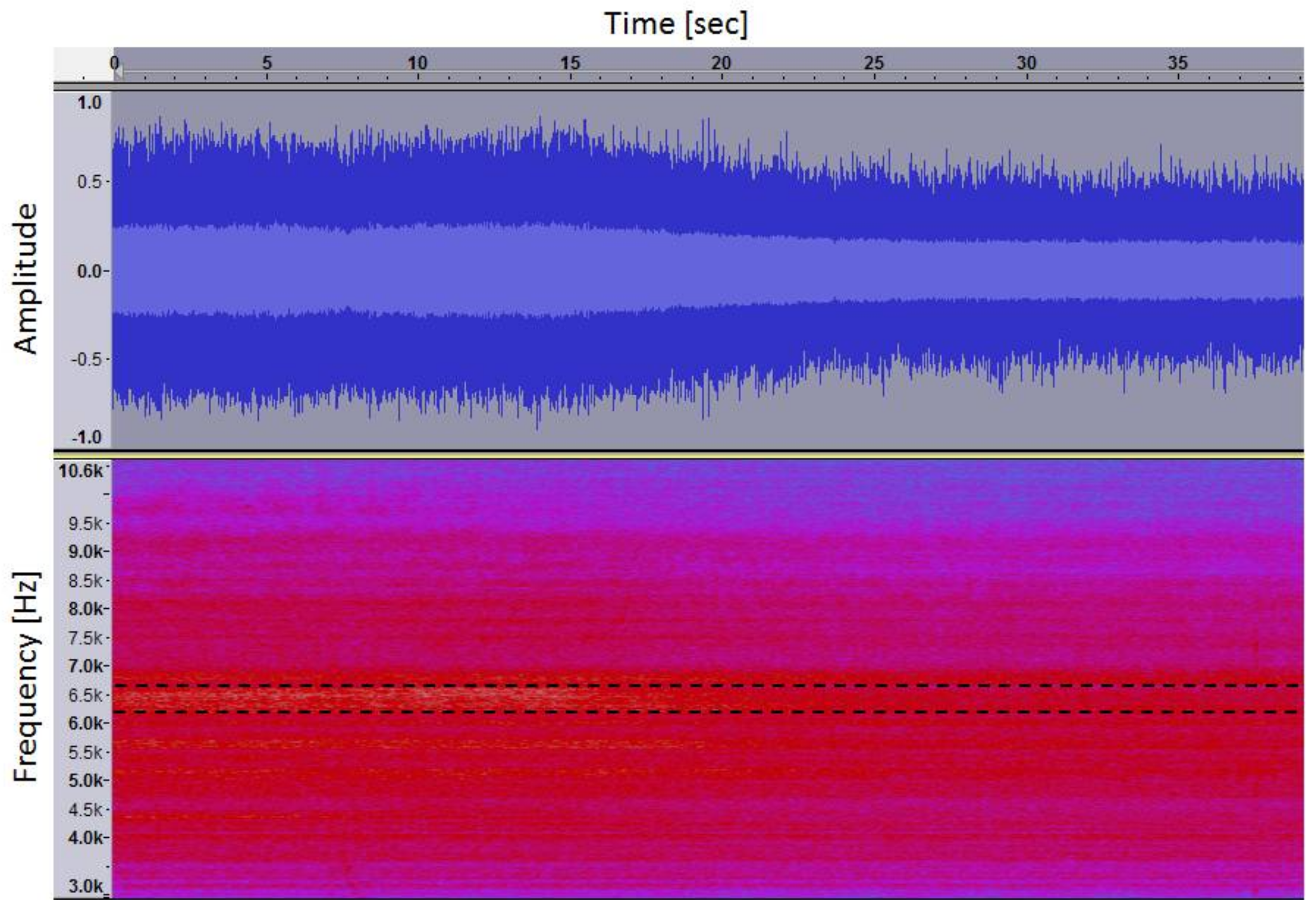
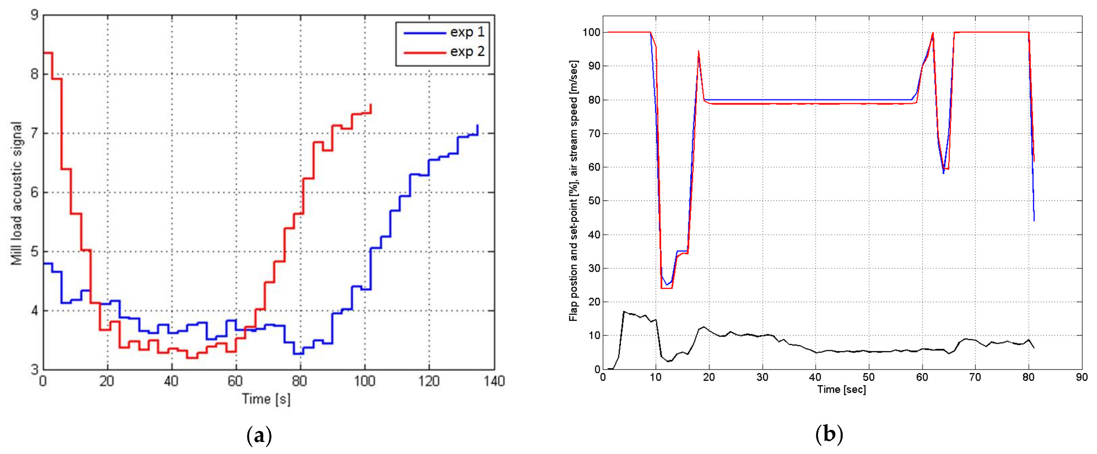
10Development of a novel acoustical method of a mill load measurement.Stabilization of the load. Efficiency of the method illustrated by exemplary experiments curried out in a real-world conditions.Inclusion of the load stabilization into control system of the overall installation; the load constitutes one of the most important state value which determines milling system efficiency.
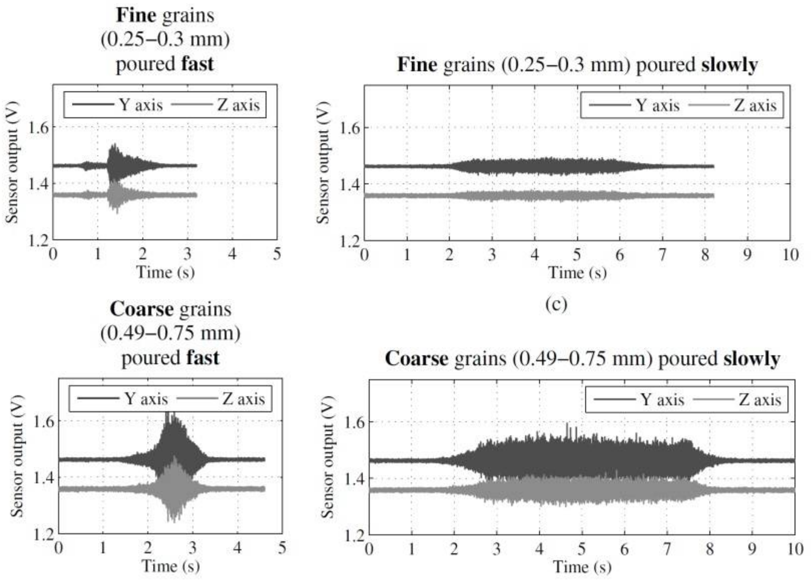
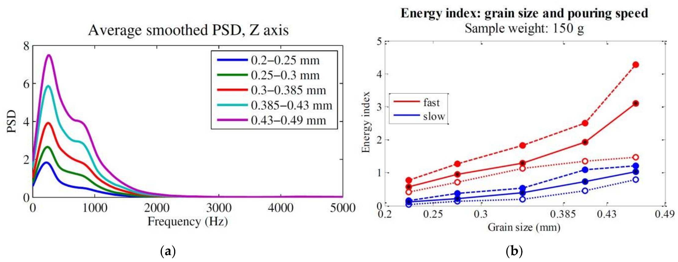
11Application of vibrational signal analysis to develop estimation method for loose material flow measurement.Construction of the laboratory rig and providing set of experimental tests. Development of the spectral energy index which allows determining grain size and pouring speed.Application of the estimation method to measure recycle stream flow to establish transporting air streams in main and recycle pipes in a control system.
12Development of a vibration-based method for online measurement of granularity and flow of loose solids.A cheap and reliable technique of contactless online granularity method is described as well as the results of tests on copper ore is presented.Application of the method in the electromagnetic mill installation system as a continuous alternative to sampled vision-based method.
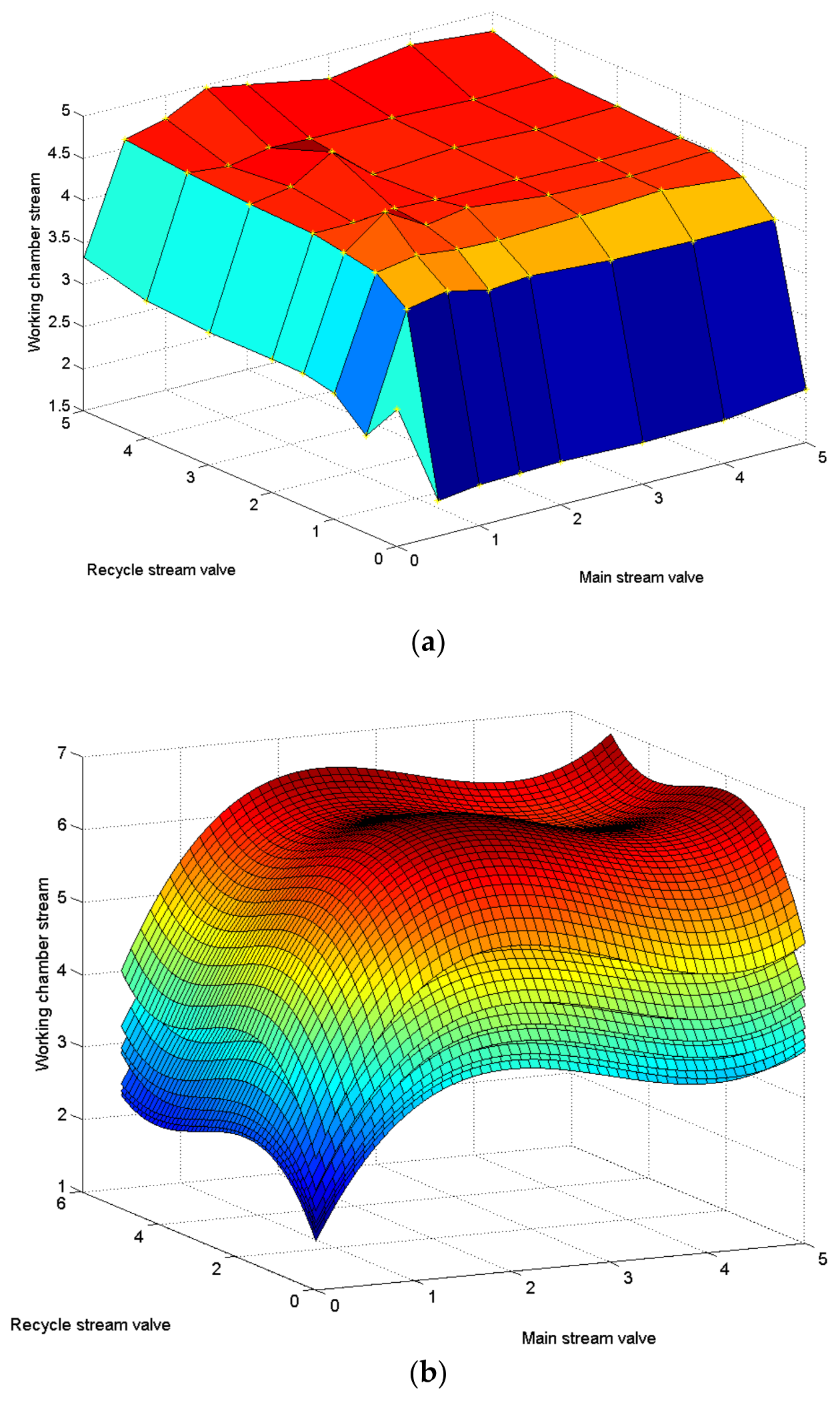
13Development of a model of the air stream ratio in electromagnetic mill installation.The concept of the grinding system is described along with indirect measurement methodology of the transporting air streams. Model structure and identification problems are discussed and a control algorithm based on the model is derived.Inclusion of the proposed algorithm in the supervisory control of the transporting air stream as a part of the overall control system which takes into account all the cross-couplings and nonlinear behavior of the system dynamics.
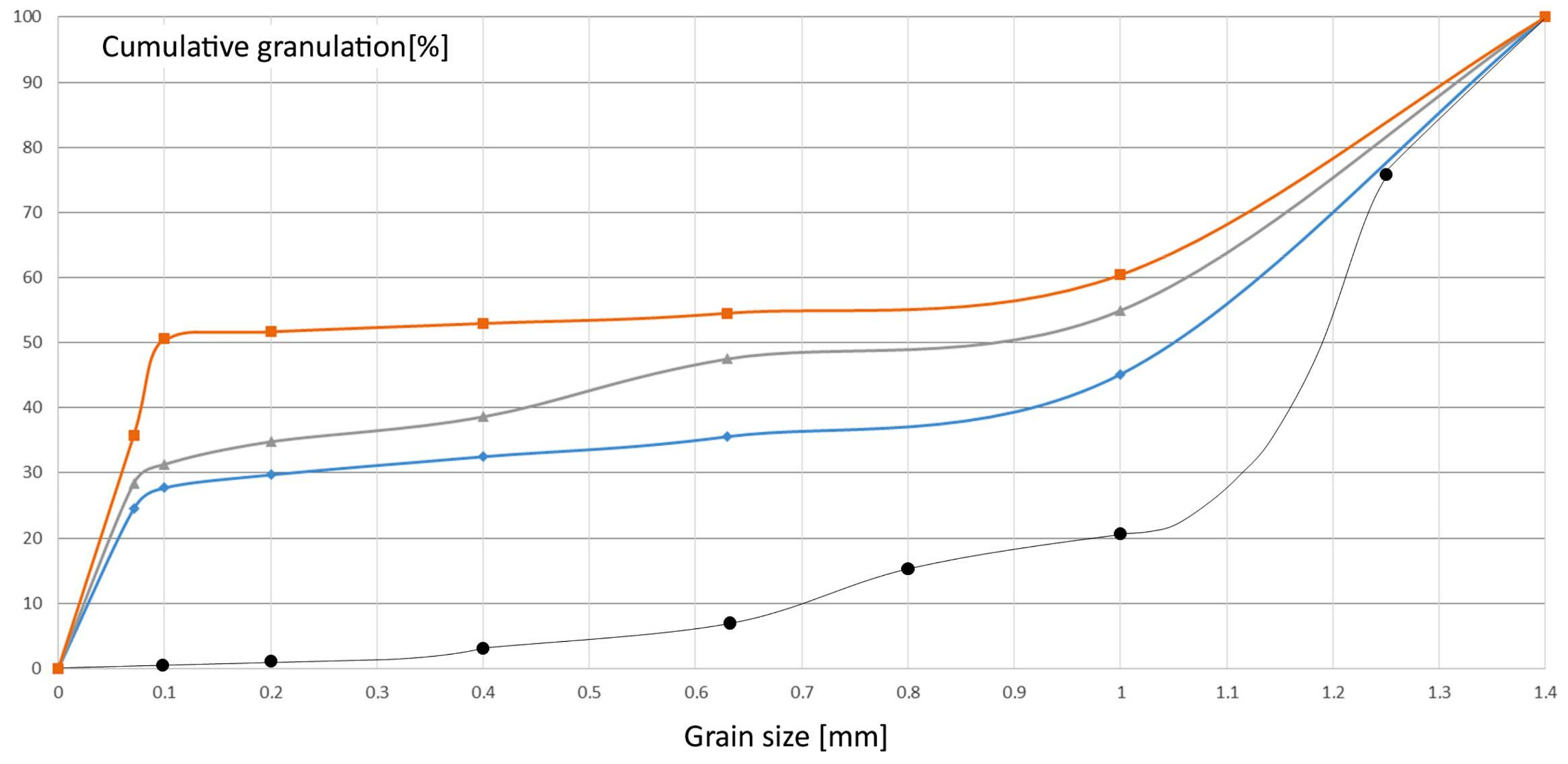
15Test of the classification method for milled material in dry transport.Test performed on the copper ore samples at laboratory rig for different operational points and a new model for partition curves description.Classification process is tuned and controlled according to obtained test results. Partition curves model is applied in supervisory layer of the hierarchical control system for the air-flow controllers set-points calculations for chosen classification point (d50 grain size).
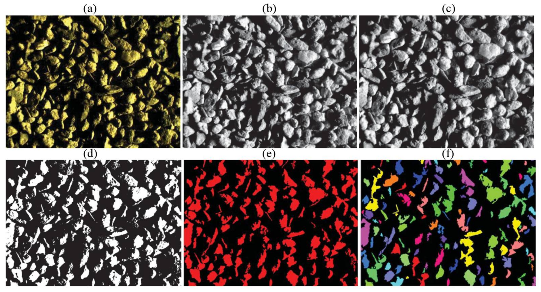
16Development of a novel method for grain size determination with inline electromagnetic mill device diagnostics.The vision camera with special lightning is used. An adaptive segmentation algorithm, is used improved with distance transform to enhance grains detection.Application of the method in pneumatic probe unit, which takes a sample from the product tube in the electromagnetic milling system which, together with vibration-based method for online measurement of granularity and flow of loose solids creates quality measurement system.
17Comparison of the grinding effectiveness of the dry and wet grinding in electromagnetic mill.Batch tests performed on copper ore in dry and wet grinding process. Energy and quality indicators proposed. Laboratory analysis results comparison and discussion.Results allows for the estimation of energy consumption and the feed-recycle ratio for dry and wet process and in turn for the process parametrization.
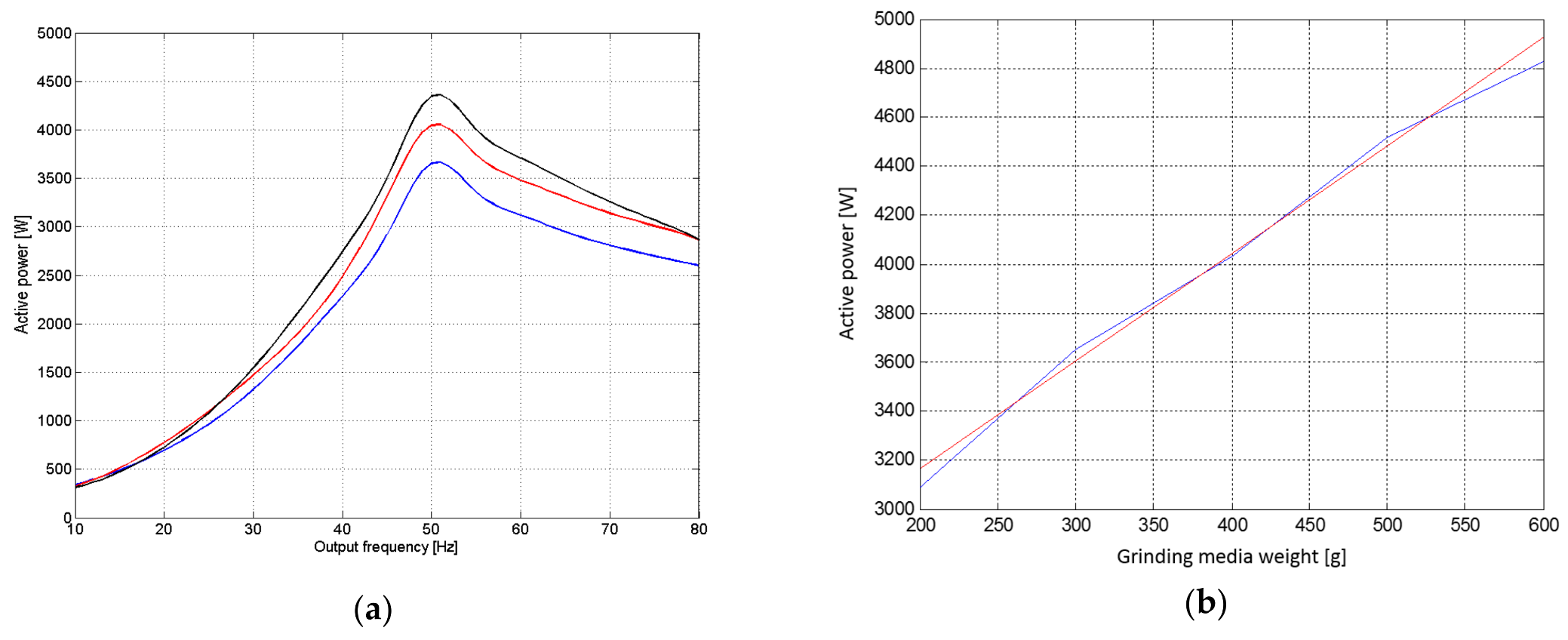
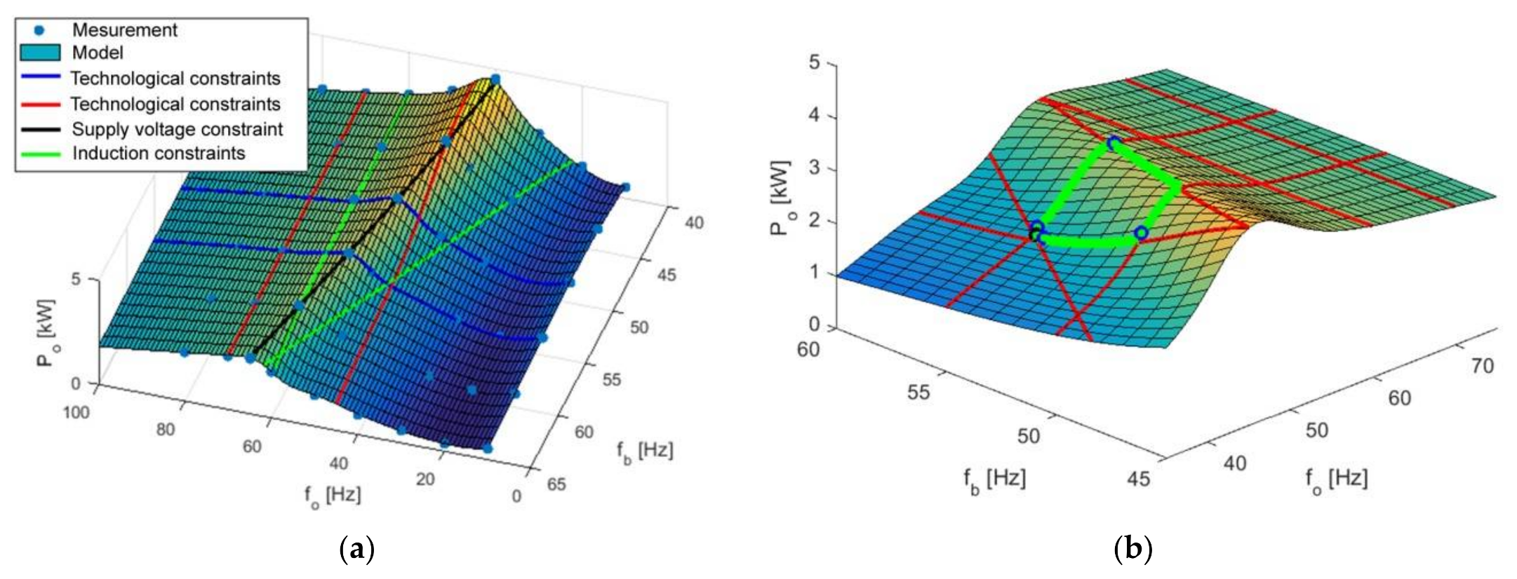
20Development of the optimizing control of electric power consumption in the electromagnetic grinding system.Description of parameters which influence product quality and formulation of the optimization problem by extraction decision variables from the set of parameters, leaving the rest as independent variables.Optimization algorithm becomes a part of the hierarchically composed multi-objective and multi-rate control system, where optimization problem is parameterized with respect to entire system parameters analysis.

References

  1. Sztaba, K. Mineral engineering. J. Pol. Miner. Eng. Soc. 2000, 1, 3–14. [Google Scholar]
  2. Fuerstenau, M.C.; Han, K.N. Principle of Mineral Processing; Society for Mining, Metallurgy, and Exploration, Inc.: Englewood, CO, USA, 2003; pp. 92–171. [Google Scholar]
  3. Garg, A.; Lam, J.S.L.; Gao, L. Energy conservation in manufacturing operations: Modelling the milling process by a new complexity-based evolutionary approach. J. Clean. Prod. 2015, 108, 34–45. [Google Scholar] [CrossRef]
  4. Tumidajski, T.; Kasińska-Pilut, E.; Gawenda, T.; Naziemiec, Z.; Pilut, R. Investigation of grinding process energy consumption and grindability of lithologic components of Polish copper ores. Miner. Resour. Manag. 2010, 26, 61–72. [Google Scholar]
  5. Walawska, B.; Szymanek, A.; Pajdak, A.; Nowak, M. Flue Gas Desulfurization by Mechanically and Thermally Activated Sodium Bicarbonate. Pol. J. Chem. Technol. 2014, 16, 56–62. [Google Scholar] [CrossRef]
  6. Staszewski, M.; Myczkowski, Z.; Bilewska, K.; Sosiński, R.; Lis, M.; Czepelak, M.; Kołacz, D. High-energy milling as a method for obtaining tetragonal form of PbO. J. Achiev. Mater. Manuf. Eng. 2012, 52, 39–46. [Google Scholar]
  7. Styła, S. A New Grinding Technology Using an Electromagnetic Mill—Testing the Efficiency of the Process. Int. Q. J. Econ. Technol. Model. Process. 2017, 6, 81–88. [Google Scholar]
  8. Wołosiewicz-Głąb, M.; Ogonowski, S.; Foszcz, D. Construction of the electromagnetic mill with the grinding system, classification of crushed minerals and the control system. In Proceedings of the 17th IFAC Symposium on Control, Optimization and Automation in Mining, Mineral and Metal Processing, Vienna, Austria, 31 August–2 September 2016. [Google Scholar]
  9. Sławiński, K.; Gandor, M.; Knaś, K.; Balt, B.; Nowak, W. Electromagnetic mill and its application for coal drying process. Rynek Energii 2014, 1, 140–150. [Google Scholar]
  10. Ogonowski, S.; Ogonowski, Z.; Swierzy, M.; Pawełczyk, S. Control system of electromagnetic mill load. In Proceedings of the 25th International Conference on Systems Engeneering, Las Vegas, NV, USA, 20–24 August 2017. [Google Scholar]
  11. Krauze, O.; Pawełczyk, M. Estimating Parameters of Loose Material Stream Using Vibration Measurements. In Proceedings of the 17th IEEE International Carpathian Control Conference, Tatranska Lomnica, Slovak, 29 May–1 June 2016. [Google Scholar]
  12. Krauze, O.; Pawełczyk, M. Evaluation of Copper Ore Granularity and Flow Rate Using Vibration Measurements. In Proceedings of the 21st International Conference on Methods and Models in Automation and Robotics, Miedzyzdroje, Poland, 29 August–1 September 2016. [Google Scholar]
  13. Ogonowski, S.; Ogonowski, Z.; Pawełczyk, M. Model of the air stream ratio for an electromagnetic mill control system. In Proceedings of the 21st International Conference on Methods and Models in Automation and Robotics, Miedzyzdroje, Poland, 29 August–1 September 2016. [Google Scholar]
  14. Wegehaupt, J.; Buchczik, D.; Krauze, O. Preliminary Studies on Modelling the Drying Process in Product Classification and Separation Path in an Electromagnetic Mill Installation. In Proceedings of the 22nd International Conference on Methods and Models in Automation and Robotics, Międzyzdroje, Poland, 28–31 August 2017. [Google Scholar]
  15. Wołosiewicz-Głąb, M.; Ogonowski, S.; Foszcz, D.; Gawenda, T. Assessment of classification with variable air flow for inertial classifier in dry grinding circuit with electromagnetic mill using partition curves. Physicochem. Probl. Miner. Process. 2018. [Google Scholar] [CrossRef]
  16. Budzan, S.; Pawełczyk, M. Grain size determination and classification using adaptive image segmentation with grain shape information for milling quality evaluation. Diagnostyka 2018, 19, 41–48. [Google Scholar] [CrossRef]
  17. Ogonowski, S.; Wołosiewicz-Głąb, M.; Ogonowski, Z.; Foszcz, D.; Pawełczyk, M. Comparison of wet and dry grinding in electromagnetic mill. Minerals 2018, in press. [Google Scholar]
  18. Pawełczyk, M.; Ogonowski, Z.; Ogonowski, S. Method for Dry Grinding in Electromagnetic Mill. Patent PL413041, 27 October 2017. [Google Scholar]
  19. Pawełczyk, M.; Ogonowski, Z.; Ogonowski, S. Method for Parametrization of Pneumatic Classifier Integrated with Mill. Patent PL413042, 27 October 2017. [Google Scholar]
  20. Ogonowski, S.; Ogonowski, Z.; Swierzy, M. Power optimizing control of grinding process in electromagnetic mill. In Proceedings of the 21st International Conference on Process Control, Štrbské Pleso, Slovak, 6–9 June 2017. [Google Scholar]
  21. Pawełczyk, M.; Ogonowski, Z.; Ogonowski, S. Control of Electromagnetic Mill Working Chamber Load in Pneumatic Transport Circuit. Patent PL421160, 15 March 2017. [Google Scholar]
  22. Swierzy, M. Optimization of Milling Process in Electromagnetic Mill. Mater’s Thesis, Silesian University of Technology, Gliwice, Poland, 2017. [Google Scholar]
Figure 1. Electromagnetic mill, ELTRAF. Electromagnets (a); The mill with the cover and working tube (b); and, Working chamber with the grinding media during operation (c).
Applsci 08 00506 g001
Figure 2. Examples of electromagnetic milling system: (a) diameter of the working chamber 100 mm; (b) 200 mm; and, (c) 320 mm (only the electromagnets yoke).
Applsci 08 00506 g002
Figure 3. General scheme of the milling system with electromagnetic mill.
Applsci 08 00506 g003
Figure 4. Sampling system (a) and system for automatic addition of the grinding media (b), both produced by Technet, Wancerzów, Poland.
Applsci 08 00506 g004
Figure 5. Cumulated mass curves of copper ore (black line—feed, blue line—product obtained for the feed volumetric flow Ff = 0.307 Mg/h, grey line—product with Ff = 0.154 Mg/h and orange line—product with Ff = 0.077 Mg/h).
Applsci 08 00506 g005
Figure 6. General structure of the plant.
Applsci 08 00506 g006
Figure 7. Time series and spectrogram of exemplary working chamber acoustic signal measurement.
Applsci 08 00506 g007
Figure 8. Example of waveforms acquired in two axes of accelerometer for fine and coarse grains transported with two speeds.
Applsci 08 00506 g008
Figure 9. Example of indirect flow measurement of solid particles: (a) power spectral densities, (b) energy index.
Applsci 08 00506 g009
Figure 10. Stages of image processing: (a) original image; (b) after histogram equalization; (c) after extraction; (d) after segmentation; (e) after refining; (f) final result.
Applsci 08 00506 g010
Figure 11. Active power of electromagnetic mill of 100 mm diameter: (a) grinding media mass 600 g—black line, 400 g—red line, 200 g—blue line; and, (b) frequency 50 Hz, measured active power and its linear model.
Applsci 08 00506 g011
Figure 12. General structure of the multilayered control system for the electromagnetic mill installation: (a)—hierarchy of the objectives; and, (b)—hardware of the control system.
Applsci 08 00506 g012
Figure 13. Functional structure of working chamber fulfilment control (measurement points are: F—flow, TI—temperature, PI—pressure, HI—humidity, X—position, LI—level, S—speed, E—voltage, FI—flow of the grains).
Applsci 08 00506 g013
Figure 14. Example of response of the direct layer control system presented in Figure 13.
Applsci 08 00506 g014
Figure 15. Example of response of the direct layer control system regulating frequency of the inverter which supplies electromagnetic mill.
Applsci 08 00506 g015
Figure 16. Models for pneumatic transporting system: (a) example of data; and, (b) model of the working chamber stream. All of the axes are expressed in V as the output of the measurement unit.
Applsci 08 00506 g016
Figure 17. (a) Model of the active power dependence on output and basic frequencies for mill 100 mm of diameter and mass of grinding media 200 g; and, (b) distribution of the magnetic induction in the working chamber for the same mill with basic frequency equal 50 Hz.
Applsci 08 00506 g017
Figure 18. (a) All of the constraints in optimization task; and, (b) feasible region.
Applsci 08 00506 g018
Figure 19. Exemplary results of the optimization run on installation 100 mm diameter. (a) without grinding media; and, (b) including grinding media: 100 g experiment 2, 150 g experiment 3, 200 g experiment 4 and 250 g experiment 5.
Applsci 08 00506 g019

