Assist-as-Needed Control of a Robotic Orthosis Actuated by Pneumatic Artificial Muscle for Gait Rehabilitation


1
Graduate School of Engineering and Science, Shibaura Institute of Technology, Saitama 337-8570, Japan
2
Department of Bioscience Engineering, Shibaura Institute of Technology, Saitama 337-8570, Japan
*
Author to whom correspondence should be addressed.
Appl. Sci. 2018, 8(4), 499; https://doi.org/10.3390/app8040499
Submission received: 26 February 2018
/
Revised: 23 March 2018
/
Accepted: 23 March 2018
/
Published: 26 March 2018
(This article belongs to the Section Mechanical Engineering)
Abstract
:Rehabilitation robots are designed to help patients improve their recovery from injury by supporting them to perform repetitive and systematic training sessions. These robots are not only able to guide the subjects’ lower-limb to a designate trajectory, but also estimate their disability and adapt the compliance accordingly. In this research, a new control strategy for a high compliant lower-limb rehabilitation orthosis system named AIRGAIT is developed. The AIRGAIT orthosis is powered by pneumatic artificial muscle actuators. The trajectory tracking controller based on a modified computed torque control which employs a fractional derivative is proposed for the tracking purpose. In addition, a new method is proposed for compliance control of the robotic orthosis which results in the successful implementation of the assist-as-needed training strategy. Finally, various subject-based experiments are carried out to verify the effectiveness of the developed control system.
1. Introduction
Robot gait training systems which help the patient regain their gait function of the lower limb via repetitive movement in training sessions have received great attention in the last decade. Most of the commercial rehabilitation systems are driven by electric motors [1,2,3,4,5,6,7,8] due to the fact that advanced control techniques can easily be applied to achieve the best performance. One typical example is the LOKOMAT system from Hocoma AG, Volketswill, Switzerland [1]. This system has not only been available on the market but also extensively studied in many rehabilitation centers. This system consists of a bodyweight support, a treadmill and a powered leg orthosis. It is capable of providing various training strategies such as trajectory tracking control and patient cooperative or assist-as-needed (AAN) [2,3,4]. The hip and knee joints are actuated by a direct current (DC) motor with helical gears. Similar systems such as ReoAmbulator (Motorika Ltd., Mount Larel, NJ, USA) [5], lower extremity powered exoskeleton (LOPES) [6,7], or active leg exoskeleton (ALEX) [8,9,10] with linear actuator are also available with AAN rehabilitation strategy. However, these motorized systems are fairly expensive due to the high cost of the servo system including the driver, motor, sensors and gear. Besides, low power/weight ratio is also a major concern.
Recently, lower-limb rehabilitation systems based on pneumatic artificial muscles (PAMs) have attracted much attention from researchers due to the similarity between PAMs and human muscle. The PAM is shortened in the longitudinal direction and enlarged in the radial direction during the contraction stage when it is being inflated, and vice versa. PAMs are light weight and exhibit a higher power/weight ratios in comparison with the motorized actuator. In addition, PAMs have a nature compliance attribute which a suitable for the human-robotics system. Thus, the applications of PAM in rehabilitation robotics field are growing despite the inherent drawbacks such as hysteresis, compressibility and time variance which yield extreme difficulties in constructing an accurate mathematical model. Various prototype systems have been developed in research centers [11,12,13,14,15,16,17,18,19,20,21,22]. To handle the nonlinear behavior of the PAM, a three-element model [23] based on the sliding mode control (SMC) has been considered as a good choice for tracking control of both single PAM [24] and robots powered by PAMs [14,15,18,19,20]. Besides, AAN strategy which provides interactive human-robot gait training is also indispensable in these systems [20,21,22]. The AAN strategy can be achieved by compliance control in which the nominal pressure of the PAM is adjusted [17,19,20,21,22].
In our previous studies [25,26,27,28,29], a high compliant gait training system actuated by PAMs based on the treadmill and body weight support (BWS) name AIRGAIT has been developed. In comparison with the existing robotic orthosis actuated by two mono-articular actuators for hip and knee joints [11,12,13,14,15,16,17,18], our developed system is based on the human musculoskeletal configuration with an additional bi-articular muscle connecting between the hip and knee joints. The existence of an antagonistic pair of bi-articular muscles can positively contribute to the compliant property of the multi-articular extremities. Furthermore, this additional actuator also provides more power for position and force control of the endpoint of the extremities, which may result in smooth, fine and precise movements [30]. Several strategies have been used for trajectory tracking control of the developed system such as co-contraction model, modified feedforward-feedback. However, the system only shows good performance without the participation of the subject at low walking speed [25,26,27]. Although the tracking performance has been improved at higher walking speed, the AAN strategy has not been integrated yet [28,29]. In addition, the mathematical model of the robot has not been considered since all control loops are designed independently.
In this research, we continue to improve on the developed lower-limb rehabilitation system. First, the dynamic model of the system is built in which the contribution of the bi-articular muscles is considered. Based on the mathematical model, a modified computed torque controller is proposed to enhance the tracking performance. This modified algorithm employs a fractional order derivative [31,32,33] which provides one more degree-of-freedom (DOF) for tuning. Then, a new compliance control method is proposed based on the estimation of a new defined human active torque. As a result, the support of the robotic orthosis varies with the disability level of patients following that the AAN strategy is achieved. Finally, experiments on the developed system with the participation of different subjects are conducted to verify the effectiveness of the proposed method.
The remaining parts of this paper are arranged as follows. The AIRGAIT orthosis description is introduced in Section 2. The mathematical model of the developed lower limb robotic orthosis is described in Section 3. The control design is shown in Section 4. Experimental results and conclusions are given in Section 5 and Section 6, respectively.
2. System Description
An overview of our developed AIRGAIT system is shown in Figure 1. This system consists of a BWS, a variable speed treadmill and an assistive lower limb gait training which comprises a robotic orthosis, spring, and parallel linkage. The spring and linkage are fixed in a sagittal plane so that the gait motion training at hip and knee joints can be realized. This research only focuses on improving the performance of the lower-limb robotic orthosis system.
The structure of the developed lower-limb robotic orthosis is shown in Figure 2a. The robotic gait training system covers the thigh at the lower end of the hip joint and shank at the lower end of the knee joint. It is actuated by PAMs in antagonistic configuration as illustrated in Figure 2b. The PAM used in this research is a self-made McKibben artificial muscle with 1.0 inch diameter. Similar to human muscle, this PAM is able to reach a maximum contraction of from the complete deflation length. The detailed parameters of PAMs are provided in Table 1. Proportional electric control valves ITV2000/3000 of SMC company are used to regulate the pressure of PAMs. The angle of knee and hip joints are measured by contactless Hall-IC named CP-20H of Midori Precisions. To implement the control algorithm, a CompactRIO platform developed by National Instrument is employed. It consists of a real-time processor for communication and signal processing, a field programmable gate array (FPGA) to run high-speed control. Besides, the sensors and control valves can be connected directly to the CompactRIO via industrial plug-in analog and digital inputs/outputs. The control algorithm is implemented and compiled by Labview software first and downloaded to CompactRIO for real-time control after that.
3. Mathematical Model of Lower-Limb Robotic Orthosis
The general configuration of a two degree of freedom (2DOF) robot is shown in Figure 3a where the subscript (hip), 2 (knee). , and are joint angles, length of links and the distance from joints to the corresponding center of mass, respectively. These parameters of the AIRGAIT robotic orthosis are provided in Table 2 in detail.
The dynamics of 2DOF robotic is described by the following Euler-Lagrange equation
where and are the vector of applied torques and joint angles, respectively. The system mass , the coriolis matrix and the vector of gravity are
with
As seen in Figure 3b, in the AIRGAIT orthosis configuration, the hip and knee joints are actuated by two mono-articular muscles, whereas the bi-articular which connects between the hip and knee joints has influence on both joints simultaneously. Hence, the relation between the torques , and generated by the corresponding pair of PAMs and the joints torques can be described by
where
and is the transformation from the muscle to joint space:
4. Control Design
4.1. Trajectory Tracking Control
Recently, the fractional order calculus has become an interesting topic and extensively used in control design [31,32,33]. In comparison with the conventional controllers based on integer order integrator and differentiator, the fractional order controller offers more degree of freedom which can be utilized to further improve the performance of the control system. The basic definitions and practical implementation of the fractional order calculus are provided in Appendix A in detail. In this research, a modified computed torque controller is proposed to enhance the tracking performance of the robotic orthosis, in the sense that the conventional integer order derivative is replaced by a fractional order one.
In Equation (13), is the reference trajectory, is the tracking error, and are positive definite gain matrices. is the differential of fractional order of e. By substituting Equation (13) into (12), the dynamics of tracking error is
Since is positive definite, the dynamics of the tracking error actually only depends on
By adjusting , and the additional fractional order , the required tracking performance can be achieved. Besides, the control law Equation (13) can be rewritten as
It can be seen from Equation (16) that the computed torque controller incorporates a feedforward and a feedback loops. In practice, the design matrices and may be chosen diagonal which results in a decoupled multi-variable linear system. Hence, the control system actually consists of three channels. The block diagram of each channel can be reconstructed as depicted in Figure 4. Particularly, the reference trajectory for the third channel, which shows the contribution of the antagonistic bi-articular muscles to the motion of the robot, is the sum of the hip and knee reference values .
4.2. Joint Compliance Control
AAN is one of the most important requirements of the robotic rehabilitation system due to the fact that the disability level of patients not only varies from subject to subject but also changes during training process with each subject. In order to implement the AAN strategy, the disability level of the patient is needed to be estimated first. Then, the compliance of the system is changed accordingly to encourage the patient effort during training.
In this study, the relationship between joint compliance and the nominal pressure in the work by Choi et al. [16] is employed. The compliance of an antagonistic actuator powered by n couple of PAMs can be described by
in which and are the parameters of the spring element of the couple of PAMs which drive actuator j, respectively. These parameters of the developed system are provided in Table 3. The length of anterior PAM corresponding to joint angle is . Note that and are regulated by the trajectory tracking controller while is fixed since it decides the initial position of the actuator. Therefore, the nominal pressure dominates the compliance of the actuators.
For estimation of the disability level, a new strategy is proposed as follows.
Define the human-robot interactive torque (HRIT) as
in which are active torques represent the contributions of subjects to the movement of the robotic orthosis. The HRIT is measured by using bar-shaped load cells attached on thigh and shank as shown in Figure 5a. If the effort of subjects is trivial, i.e., , the signals provided by the load cells represent the HRIT of the passive mode in which the disability level of the patient is highest and the robotic orthosis provides full support to dominate the movement of the lower limb. In this case, is saved as the torque profile of the subject as illustrated by the black line in Figure 5b. If the subject generates active force which positively contributes to the movement (), the signal from load cells tends to be smaller in comparison with (Zone A in Figure 5b). In contrast, increases when the active force against the movement of the robotic lower limb () which is illustrated by Zone B in Figure 5b. This difference can be treated as human active torque and is utilized to adjust the compliance of the robotic orthosis. Since not only varies from subjects to subjects, but also changes with the same subject during the training process, the following procedure is proposed to online estimate .
Step 1: At the beginning of the training process, the subject is asked to walk on the treadmill in passive mode with full support from the robotic orthosis. Then, the data from the load cells attached to the thigh and shank positions in 30 gait cycles (GCs) are saved as . This data is the basic profile of each subject and used during the training process.
Step 2: In this step, the subject is encouraged to move actively. The signals from the load cells in this step represent . The active torque generated by human effort can be estimated by
Based on the estimated , the compliance of the robotic orthosis is adjusted by the following rule
In Equation (20), is the width of a boundary layer in which is the center. In experiment . is the gain of the compliance controller and is the sign function of x:
The block diagram of the proposed control system for each channel including AAN strategy is shown in Figure 6.
5. Experimental Evaluation
5.1. Experimental Procedure
To evaluate the performance of the proposed control strategy with the developed lower-limb robotic orthosis system, various experiments are conducted with the participation of eight healthy male subjects who do not have neurological disorders. The detail information of these subjects are given in Table 4. All subjects gave their written informed consents for inclusion before they participated in the experiments. The experiment protocol was approved by the Ethics Committee of Shibaura Institute of Technology.
The system is evaluated in two gait training modes including trajectory tracking mode and compliance control mode. The experiment time for each subject is about 10 min. In the first 5 min when the trajectory tracking mode is tested the robot compliance is set to the minimum value so that the movement of the subject lower limb is dominated by the robotic orthosis. The subject is also asked to completely relax. Therefore, the data of in 30 GCs are collected and saved together with the desired and measured trajectories. In the next 5 min of the experiment, the robotic orthosis is switched to the compliance control mode. In this case, the subject is asked to be more active in moving. The data are also recorded in last 30 GCs for further analysis.
During the experiments, the body weight support system is used due to the safety requirements for the subjects. The reference trajectories of the hip () and knee () mono-articular actuator are modified from the gait data profile in textbook [35] according to each subject with the maximum of hip and knee flexion/extension angles are +20/−20 and 45/0, respectively. The speed of the treadmill is set at 2.2 km/h. The sampling frequency of the control system is 100 Hz. Low pass filters with unity gain and 6 Hz cut-off frequency are employed to reduce the noise from signals getting from the load cells, pressure sensors as well the angle sensors. All analyses are carried out by MATLAB (MathWorks, Natick, MA, USA) software version R2016a. The parameters of the controllers after being well tuned are provided in Table 5.
5.2. Experimental Results
5.2.1. Trajectory Tracking Control
Firstly, the experiments to compare the performance of the conventional computed torque control and the proposed controller are conducted. These experiments are carried out without the participation of a subject. The results are shown in Figure 7.
It can be seen that by adjusting the additional parameter, i.e. the fractional order , the tracking performance is significantly improved. With the proposed control method, the system reaches the steady state in 2 GCs and the root mean square tracking error (RMSTE) are and for hip and knee joints, respectively. With the conventional computed torque controller, these values are and , moreover the system can only reach the steady state in 5 GCs. All data are provided in Table 6 in detail. The RMSTE is computed by
in which N is the total number of sampled data.
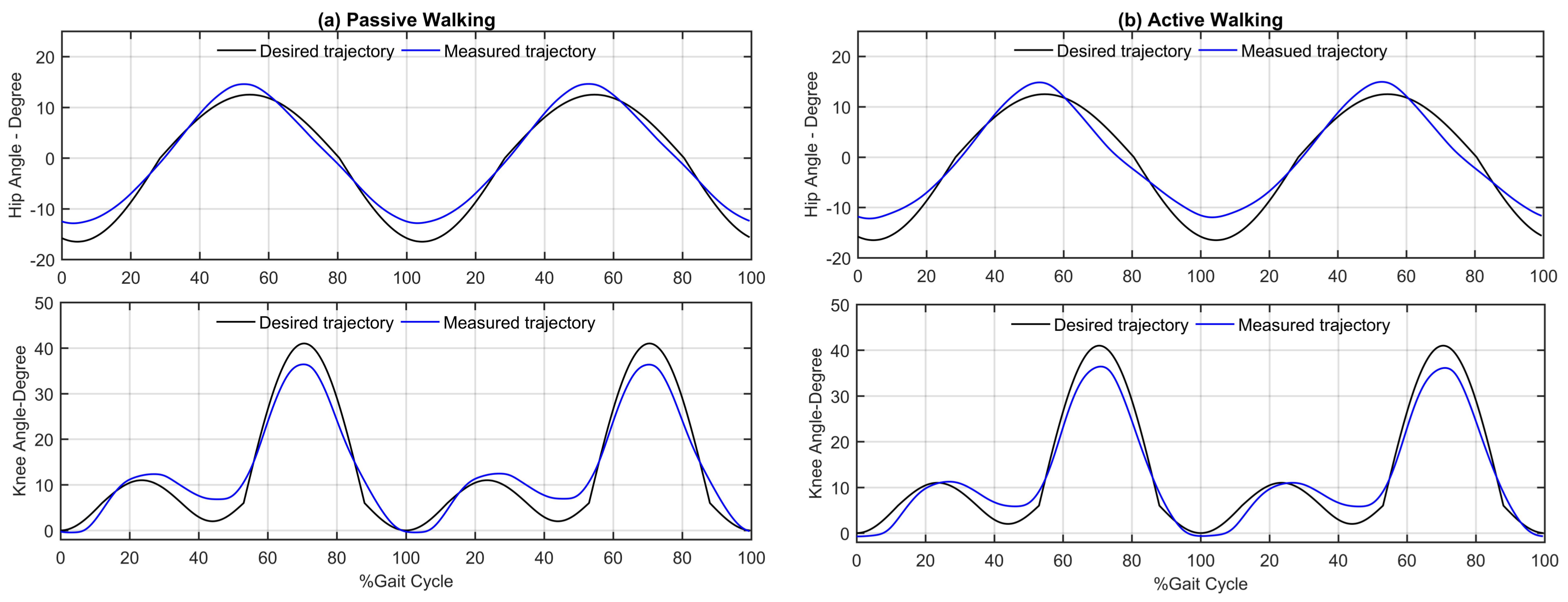
The process starts with the computerised record of the mean of all measured trajectories of participants to evaluate the performance of the system during trajectory tracking mode. Then follows by the maximum tracking error (MTE) and the RMSTE between the average and the desired trajectory are evaluated. Throughout the process, standard deviations (SDs) over the maximum joint angular and compliance errors of subjects are also considered for further study on the intersubject variability. These results are shown in detail in Table 7. The experimental results in passive and active modes are also depicted in Figure 8. As can be observed in Table 7, the MTE and RMSTE are below and for both hip and knee joints in passive walking mode. In active mode where the participants contribute force to the movement of their lower limb, the tracking performance is slightly degraded, i.e., and . These results are deemed suitable for rehabilitation system in practice. Also, the small value of SDs means that the control system is robust against the variance of the subjects and is able to guide different types of patients in the rehabilitation process.
5.2.2. Joint Compliance Control
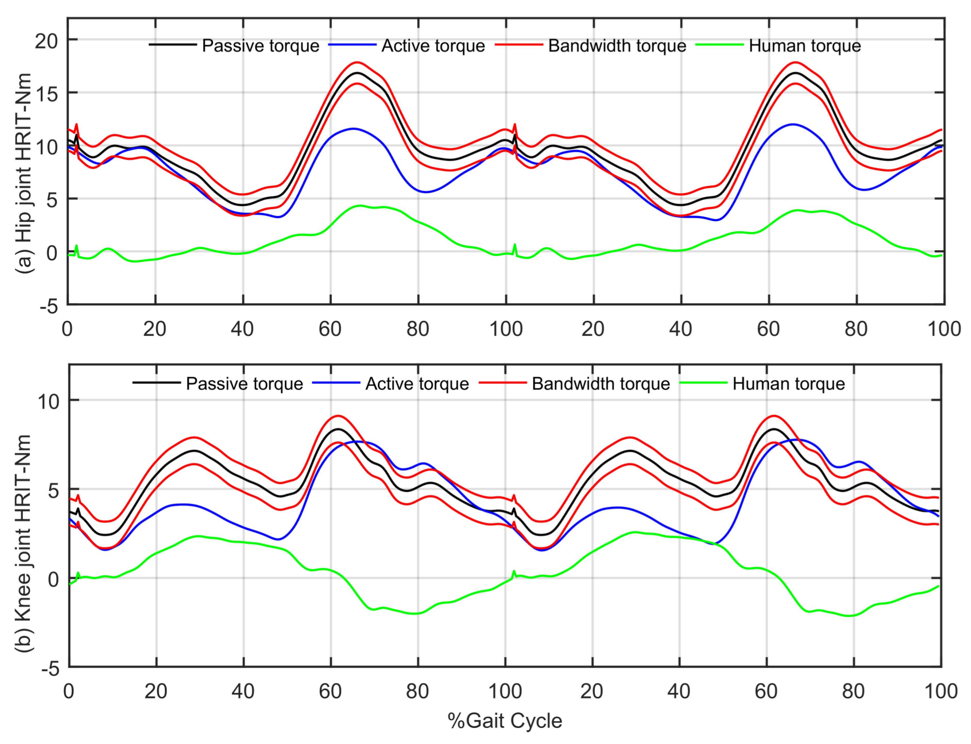
The joint compliance of the robotic orthosis in tracking control and impedance control mode in sagittal plane are shown in Figure 9. The torque profile of subjects (the black line) and the estimation of the active human torque (the green line) are depicted in Figure 10. All these data are also averaged over all subjects for two GCs.
It can be observed that in passive mode, the compliance is set at low level such that movement of the lower limb is dominated by the robotic orthosis. When the subject is in active mode, is outside the bandwidth where the center is the passive one . Consequently, the compliance controller increases the joint compliance to encourage the contributions of the subjects in training process. For example, in the first half of GC which means the robotic orthosis reduces the support to the subjects. The unexpected behavior of the system in the range of 60% to 100 % of gait cycle in knee joint may be caused by the healthy subjects whose contribution against the movement of the robotic. However, the adaptation of the compliance demonstrated that the compliance controller is able to provide the assistance based on the effort of the subjects while the tracking controller is still stable to guide the subject limb.
6. Conclusions and Discussion
In this paper, the control system for the developed AIRGAIT lower limb robotic orthosis is continued to be improved. First, the mathematical model of the robotic orthosis manipulated by additional bi-articular muscles is built. Based on the mathematical model, a modified computed torque controller, which utilizes the fractional order derivative is proposed for trajectory tracking mode. By adjusting the additional parameter, i.e., the fractional order of the derivative, the tracking performance is significantly improved in both transient and steady-state. Then, a new compliance controller based on new defined human-robot interactive torque and human active torque is proposed. As a result, AAN strategy is successfully implemented, i.e., the robotic orthosis dominates the movement of subjects in passive mode and reduces the support when the subjects become more active. Finally, the effectiveness of the proposed strategy is confirmed by various experiments with the participation of eight healthy subjects. Particularly, all the subjects report that they feel comfortable during the experiments.
The MTE of hip and knee joint are less than during the experiments. This control performance is in accordance with the result achieved in [19,20,21,22] in which the 6-DOFs gait rehabilitation orthosis powered by PAMs is used, i.e., MTE < . However, the walking speed of the proposed system, i.e., 2.2 km/h, is lower than of its 6-DOF robot orthosis system counter part, i.e., 2.5 km/h. The trajectory tracking control strategy of 6-DOF system based on the boundary layer augmented sliding control (BASMC) law [19,20] and the chattering free robust variable structure controller (CRVC) [21,22], whereas the proposed system employed the modified computed torque control scheme with one more fractional order derivative for tracking purposed. Although, the nominal pressure is also used for AAN, the proposed strategy required less force sensors, i.e., 2 bar-shaped load cells attached at COM of thigh and shank part, in comparison with 4 load cells connected in series with each PAM in the 6-DOF robot system. Moreover, the use of actuator configuration based on the human musculoskeletal system also provides more power and redundant for the system.
In future work, the improvement of the AAN controller which is able to adapt the robotic orthosis compliance according to the muscle responses of the patient is considered. Due to the fact that the patient disability is caused by different reasons, i.e., stroke or spinal cord injury, etc. which results in different responses of the patient muscles, the use of electromyography (EMG) sensor is going to be exploited. In that case, the AAN controller may evaluate the active levels of the muscles and provide the assistance accordingly. This is expected to enhance the patient’s volition during the gait training process.
Author Contributions
Quy-Thinh Dao conceived the methodology and developed the experiment, he also performed the experiment, analyzed data and wrote the paper. Shin-ichiroh Yamamoto led the research efforts and led the preparation of this paper.
Conflicts of Interest
The authors declare no conflict of interest.
Appendix A. Fractional Order Calculus
Fractional-order calculus is a generalization of the integration and differentiation from integer to non-integer order. This appendix introduces only definitions which are widely used in the area of control system.
First, the gamma function which is the extension of the factorial for non-integer number z is introduced
The most important property of the gamma function is
Then, the definition of derivative of order is presented. In continuous-time domain, the most often used one is the Riemann-Liouville definition
where and t are the limits and n is an integer number satisfying . In practical applications where computer-based control devices are used, the following - definition with short memory principle is preferred:
in which means the integer part, is the sampling time and is the binomial coefficient defined by
References
- Behrman, A.L.; Harkema, S.J. Locomotor training after human spinal cord injury: A series of case studies. Phys. Ther. 2000, 80, 688–700. [Google Scholar] [PubMed]
- Jezernik, S.; Colombo, G.; Morari, M. Automatic gait-pattern adaptation algorithms for rehabilitation with a 4-DOF robotic orthosis. IEEE Trans. Robot. Autom. 2004, 20, 574–582. [Google Scholar] [CrossRef]
- Von Zitzewitz, J.; DuschauWicke, A.; Caprez, A.; Lunenburger, L.; Riener, R. Path control: A method for patient-cooperative robot aided gait rehabilitation. IEEE Trans. Neural Syst. Rehabil. Eng. 2010, 18, 38–48. [Google Scholar] [CrossRef] [Green Version]
- Duschau-Wicke, A.; Caprez, A.; Riener, R. Patient-cooperative control increases active participation of individuals with SCI during robot-aided gait training. J. Neuroeng. Rehabil. 2010, 7. [Google Scholar] [CrossRef] [PubMed] [Green Version]
- Fisher, S.; Lucas, L.; Adam Thrasher, T. Robot-Assisted Gait Training for Patients with Hemiparesis Due to Strok. Top. Stroke Rehabil. 2011, 18, 269–276. [Google Scholar] [CrossRef] [PubMed]
- Veneman, J.F.; Kruidhof, R.; Hekman, E.E.G.; Ekkelenkamp, R.; Van Asseldonk, E.H.F.; Van Der Kooij, H. Design and evaluation of the LOPES exoskeleton robot for interactive gait rehabilitation. IEEE Trans. Neural Syst. Rehabil. Eng. 2007, 15, 379–386. [Google Scholar] [CrossRef] [PubMed]
- Van Asseldonk, E.H.F.; Veneman, J.F.; Ekkelenkamp, R.; Buurke, J.H.; van der Helm, F.C.T.; van der Kooij, H. The Effects on Kinematics and Muscle Activity of Walking in a Robotic Gait Trainer During Zero-Force Control. IEEE Trans. Neural Syst. Rehabil. Eng. 2008, 16, 360–370. [Google Scholar] [CrossRef] [PubMed]
- Banala, S.K.; Kim, S.H.; Agrawal, S.K.; Scholz, J.P. Robot assisted gait training with active leg exoskeleton (ALEX). IEEE Trans. Neural Syst. Rehabil. Eng. 2009, 17, 2–8. [Google Scholar] [CrossRef] [PubMed]
- Banala, S.K.; Agrawal, S.K.; Kim, S.H.; Scholz, J.P. Novel gait adaptation and neuromotor training results using an active leg exoskeleton. IEEE/ASME Trans. Mechatron. 2010, 15, 216–225. [Google Scholar] [CrossRef]
- Srivastava, S.; Kao, P.C.; Kim, S.H.; Stegall, P.; Zanotto, D.; Higginson, J.S.; Agrawal, S.K.; Scholz, J.P. Assist-as-Needed Robot-Aided Gait Training Improves Walking Function in Individuals Following Stroke. IEEE Trans. Neural Syst. Rehabil. Eng. 2015, 23, 956–963. [Google Scholar] [CrossRef] [PubMed]
- Gordon, K.E.; Sawicki, G.S.; Ferris, D.P. Mechanical performance of artificial pneumatic muscles to power an ankle-foot orthosis. J. Biomech. 2006, 39, 1832–1841. [Google Scholar] [CrossRef] [PubMed]
- Beyletal, P. Safe and compliant guidance by a powered knee exoskeleton for robot-assisted rehabilitation of gait. Adv. Robot. 2011, 25, 513–535. [Google Scholar] [CrossRef]
- Sawicki, G.S.; Ferris, D.P. A pneumatically powered knee-ankle-foot orthosis (KAFO) with myoelectric activation and inhibition. J. Neuroeng. Rehabil. 2009, 6. [Google Scholar] [CrossRef] [PubMed]
- Lilly, J.H.; Quesada, P.M. A two-input sliding-mode controller for a planar arm actuated by four pneumatic muscle groups. IEEE Trans. Neural Syst. Rehabil. Eng. 2004, 12, 349–359. [Google Scholar] [CrossRef] [PubMed]
- Lilly, J.H.; Yang, L. Sliding mode tracking for pneumatic muscle actuators in opposing pair configuration. IEEE Trans. Control Syst. Technol. 2005, 13, 550–558. [Google Scholar] [CrossRef]
- Choi, T.Y.; Lee, J.J. Control of Manipulator Using Pneumatic Muscles for Enhanced Safety. IEEE Trans. Ind. Electron. 2010, 57, 2815–2825. [Google Scholar] [CrossRef]
- Choi, T.Y.; Choi, B.S.; Seo, K.H. Position and Compliance Control of a Pneumatic Muscle Actuated Manipulator for Enhanced Safety. IEEE Trans. Control Syst. Technol. 2011, 19, 832–842. [Google Scholar] [CrossRef]
- Hussain, S.; Xie, S.Q.; Jamwal, P.K.; Parsons, J. An intrinsically compliant robotic orthosis for treadmill training. Med. Eng. Phys. 2012, 34, 1448–1453. [Google Scholar] [CrossRef] [PubMed]
- Hussain, S.; Xie, S.Q.; Jamwal, P.K. Control of a robotic orthosis for gait rehabilitation. Robot. Auton. Syst. 2013, 61, 911–919. [Google Scholar] [CrossRef]
- Hussain, S.; Xie, S.Q.; Jamwal, P.K. Adaptive Impedance Control of a Robotic Orthosis for Gait Rehabilitation. IEEE Trans. Cybern. 2013, 43, 1025–1034. [Google Scholar] [CrossRef] [PubMed]
- Hussain, S.; Xie, S.Q.; Jamwal, P.K. Robust Nonlinear Control of an Intrinsically Compliant Robotic Gait Training Orthosis. IEEE Trans. Syst. Man Cybern. Syst. 2013, 43, 655–665. [Google Scholar] [CrossRef]
- Hussain, S.; Jamwal, P.K.; Ghayesh, M.H.; Xie, S.Q. Assist-as-Needed Control of an Intrinsically Compliant Robotic Gait Training Orthosis. IEEE Trans. Ind. Electron. 2017, 64, 1675–1685. [Google Scholar] [CrossRef]
- Reynolds, D.B.; Repperger, D.W.; Phillips, C.A.; Bandry, G. Dynamic characteristics of pneumatic muscle. Ann. Biomed. Eng. 2003, 31. [Google Scholar] [CrossRef]
- Xing, K.; Huang, J.; Wang, Y.; Wu, J.; Xu, Q.; He, J. Tracking control of pneumatic artificial muscle actuators based on sliding mode and non-linear disturbance observer. IET Control Theory Appl. 2010, 4. [Google Scholar] [CrossRef]
- Shibata, Y.; Imai, S.; Nobutomo, T.; Miyoshi, T.; Yamamoto, S.I. Development of body weight support gait training system using antagonistic bi-articular muscle model. In Proceedings of the 2010 Annual International Conference of the IEEE Engineering in Medicine and Biology, Buenos Aires, Argentina, 31 August–4 September 2010; pp. 4468–4471. [Google Scholar] [CrossRef]
- Yamamoto, S.I.; Shibata, Y.; Imai, S.; Nobutomo, T.; Miyoshi, T. Development of gait training system powered by pneumatic actuator like human musculoskeletal system. In Proceedings of the 2011 IEEE International Conference on Rehabilitation Robotics, Zurich, Switzerland, 29 June–1 July 2011; pp. 1–4. [Google Scholar] [CrossRef]
- Mat Dzahir, M.A.; Nobutomo, T.; Yamamoto, S.I. Development of body weight support gait training system using pneumatic mckibben actuators -Control of Lower Extremity Orthosis-. In Proceedings of the 2013 35th Annual International Conference of the IEEE Engineering in Medicine and Biology Society (EMBC), Osaka, Japan, 3–7 July 2013; pp. 6417–6420. [Google Scholar] [CrossRef]
- Dao, Q.T.; Yamamoto, S.I. Design and Evaluation of the Lower-limb Robotic Orthosis for Gait Rehabilitation Actuated by Pneumatic Artificial Muscle. In Proceedings of the 2017 2nd International Conference on Biomedical Signal and Image Processing (ICBIP 2017), Kitakyushu, Japan, 23–25 August 2017. [Google Scholar]
- Dao, Q.T.; Yamamoto, S.I. Tracking control of a robotic orthosis for gait rehabilitation: A feedforward-feedback control approach. In Proceedings of the 2017 10th Biomedical Engineering International Conference (BMEiCON), Hokkaido, Japan, 31 August–2 September 2017; pp. 1–5. [Google Scholar] [CrossRef]
- Kumamoto, M.; Oshima, T.; Yamamoto, T. Control properties induced by the existence of antagonistic pairs of bi-articular muscles—Mechanical engineering model analyses. Human Mov. Sci. 1994, 13, 611–634. [Google Scholar] [CrossRef]
- Chen, Y.; Petras, I.; Xue, D. Fractional order control—A tutorial. In Proceedings of the 2009 American Control Conference, St. Louis, MO, USA, 10–12 June 2009; pp. 1397–1411. [Google Scholar] [CrossRef]
- Efe, M.Ö. Fractional Order Systems in Industrial Automation—A Survey. IEEE Trans. Ind. Inform. 2011, 7, 582–591. [Google Scholar] [CrossRef]
- Shah, P.; Agashe, S. Review of fractional PID controller. Mechatronics 2016, 38, 29–41. [Google Scholar] [CrossRef]
- Horata, P.; Chiewchanwattana, S.; Sunat, K. A comparative study of pseudo-inverse computing for the extreme learning machine classifier. In Proceedings of the 3rd International Conference on Data Mining and Intelligent Information Technology Applications, Coloane, Macao, 24–26 October 2011; pp. 40–45. [Google Scholar]
- Winter, D.A. Biomechanics and Motor Control of Human Movement, 3rd ed.; University of Waterloo Press: Waterloo, ON, Canada, 1990. [Google Scholar]
Figure 1.
The AIRGAIT system.
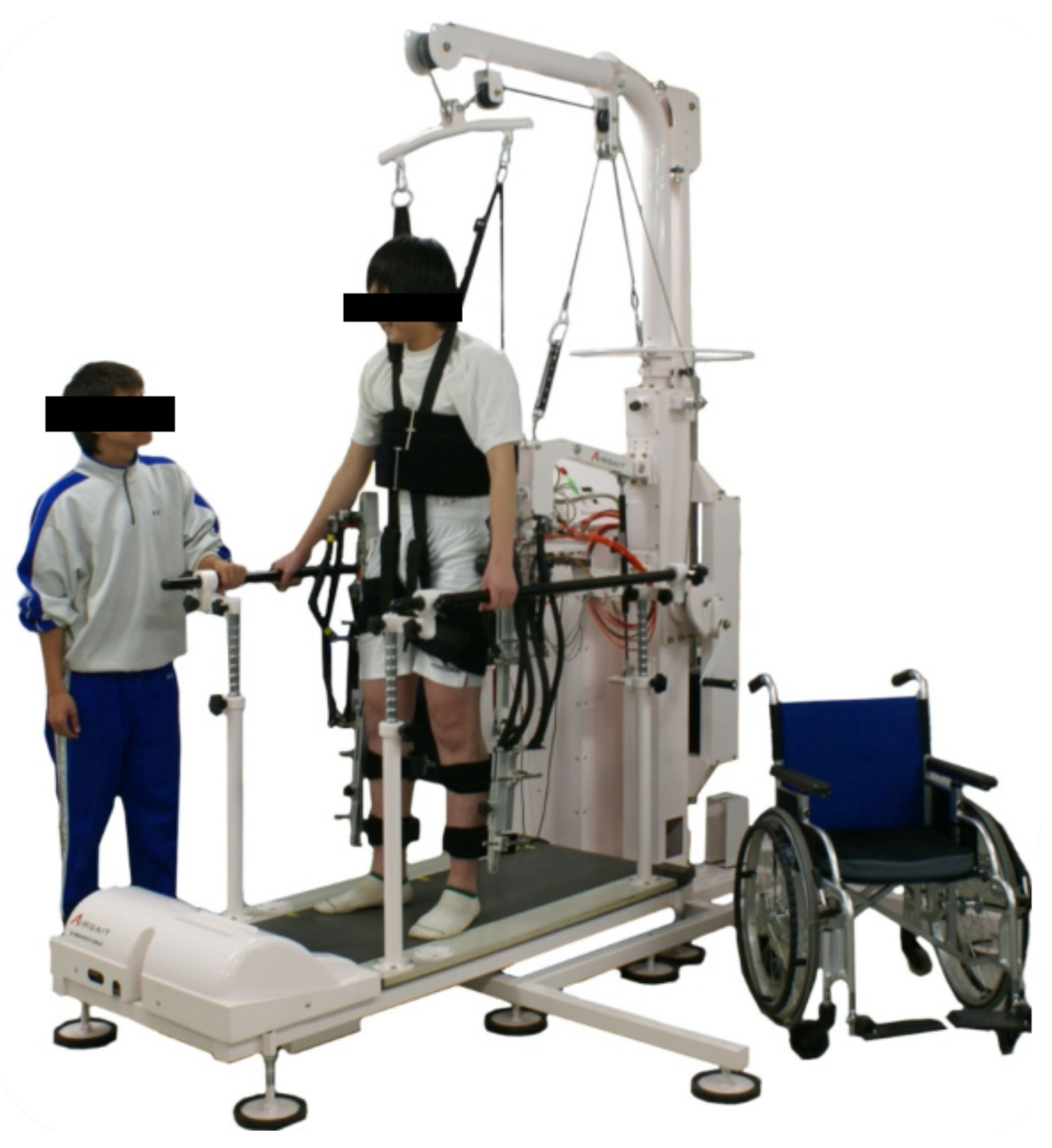
Figure 2.
(a) The developed lower-limb robotic orthosis; (b) A typical antagonistic configuration.
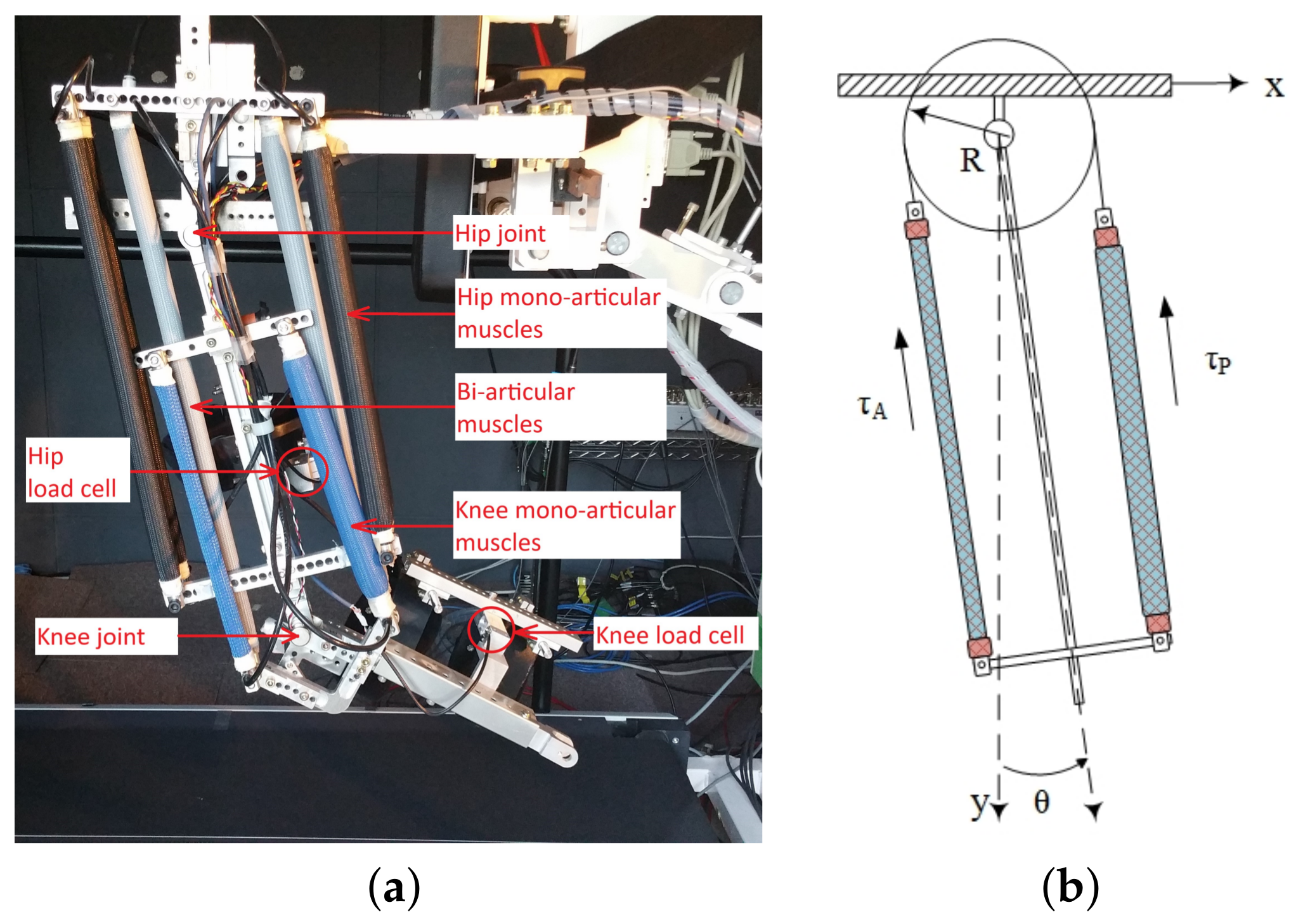
Figure 3.
(a) Typical 2DOF robotic (b) Robotic Orthosis with two mono-articular and one bi-articular muscles. The 1, 2, 3 subscripts denote hip, knee and bi-articular muscle. A and P subscripts denote the anterior and posterior PAMs.
Figure 3.
(a) Typical 2DOF robotic (b) Robotic Orthosis with two mono-articular and one bi-articular muscles. The 1, 2, 3 subscripts denote hip, knee and bi-articular muscle. A and P subscripts denote the anterior and posterior PAMs.
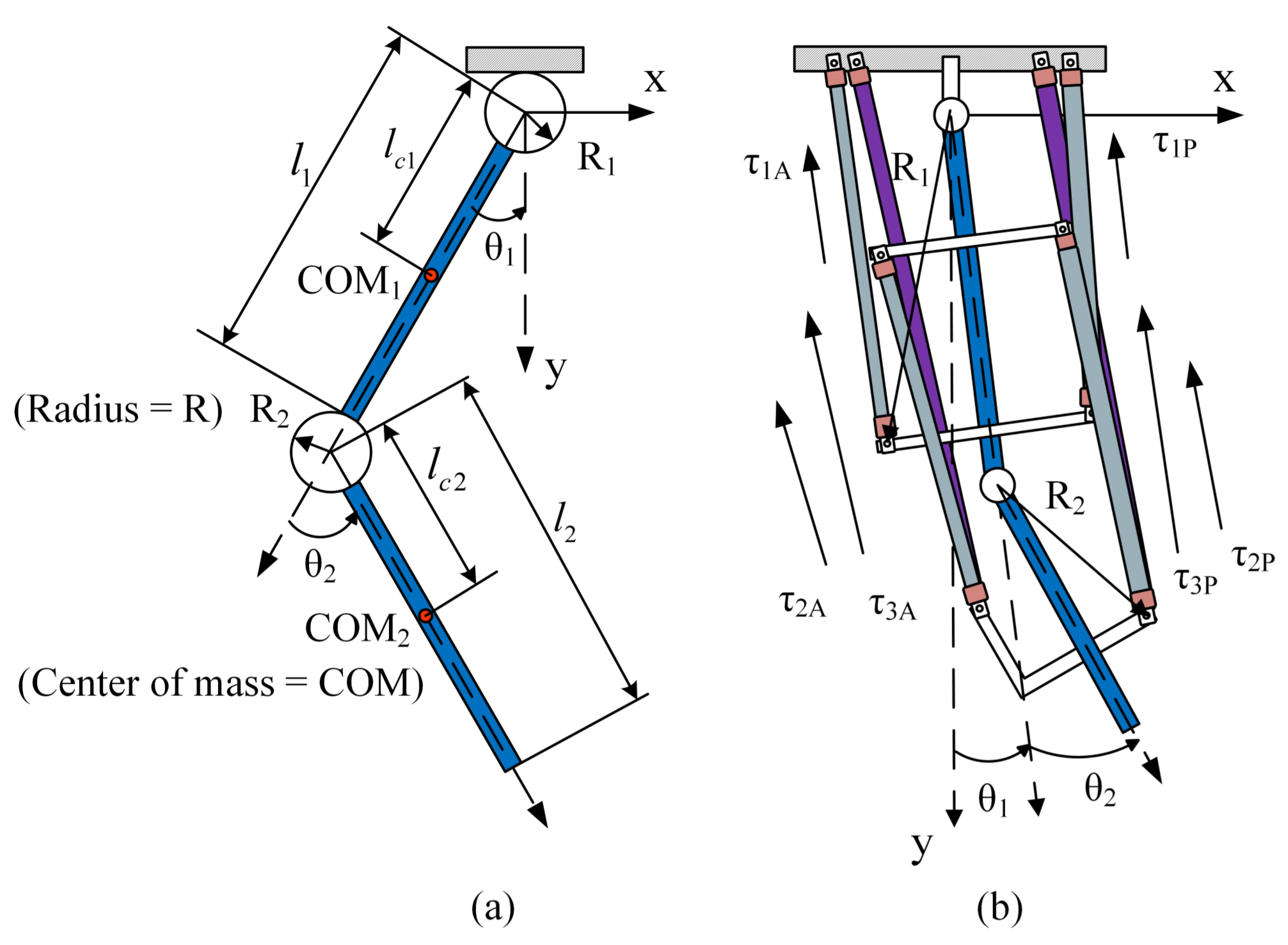
Figure 4.
The block diagram of decoupled channels. is the nominal pressure supplied to the PAM, is the different pressure of two PAMs.
Figure 4.
The block diagram of decoupled channels. is the nominal pressure supplied to the PAM, is the different pressure of two PAMs.

Figure 5.
The compliance control method of the AIRGAIT robot orthosis: (a) The position of the load cell on robot orthosis and (b) the dependence of the robot compliance base on the human effort.
Figure 5.
The compliance control method of the AIRGAIT robot orthosis: (a) The position of the load cell on robot orthosis and (b) the dependence of the robot compliance base on the human effort.
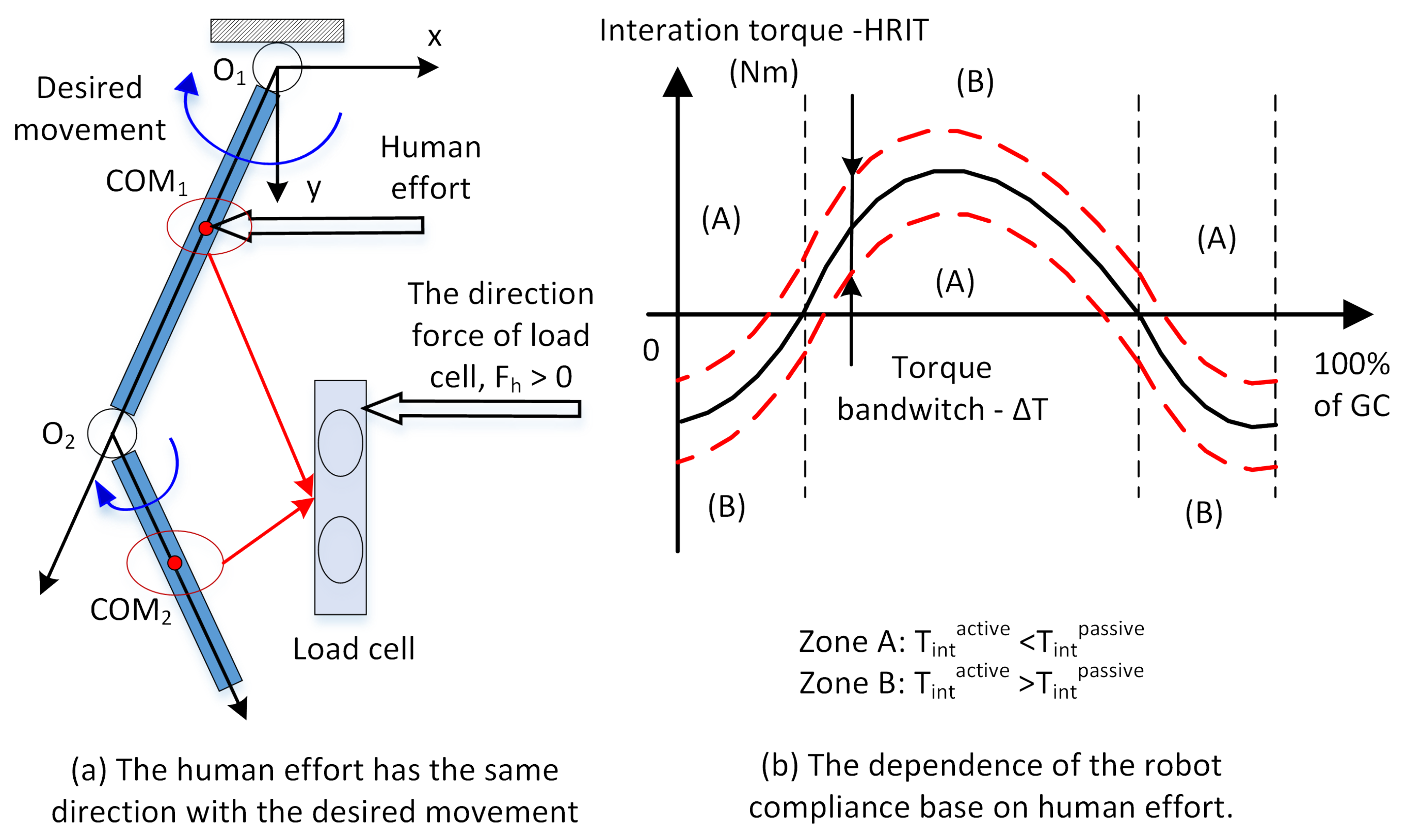
Figure 6.
Compliance control architecture of the AIRGAIT robotic orthosis.

Figure 7.
Comparative results between the conventional and proposed computed torque control: (a) The hip joint and (b) the knee joint.
Figure 7.
Comparative results between the conventional and proposed computed torque control: (a) The hip joint and (b) the knee joint.

Figure 8.
Trajectory tracking control performance of AIRGAIT robotic orthosis in: (a) passive mode and (b) active mode. The gait data is normalized and plotted as reference trajectories.
Figure 8.
Trajectory tracking control performance of AIRGAIT robotic orthosis in: (a) passive mode and (b) active mode. The gait data is normalized and plotted as reference trajectories.

Figure 9.
Joint sagittal plane compliance of AIRGAIT robot orthosis: (a) Hip joint and (b) Knee joint.
Figure 9.
Joint sagittal plane compliance of AIRGAIT robot orthosis: (a) Hip joint and (b) Knee joint.
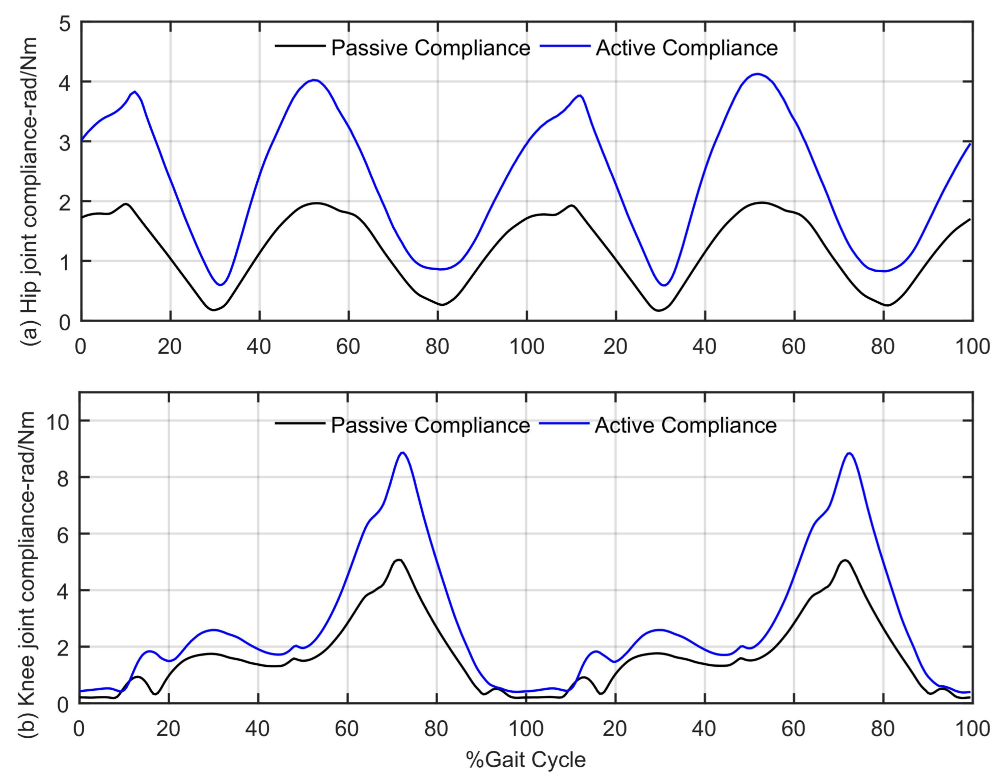
Figure 10.
The human-robot interactive torque (HRIT) of AIRGAIT robotic orthosis during active and passive modes: (a) Hip joint and (b) Knee joint.
Figure 10.
The human-robot interactive torque (HRIT) of AIRGAIT robotic orthosis during active and passive modes: (a) Hip joint and (b) Knee joint.

Table 1.
The nominal length and nominal pressure () of each pneumatic artificial muscles (PAMs).
| Actuators | Nominal Length [cm] | Nominal Pressure [×100 kPa] | ||
|---|---|---|---|---|
| Anterior | Posterior | Anterior | Posterior | |
| Knee mono-articular | 40 | 40 | 3.5 | 1.0 |
| Hip mono-articular | 55 | 55 | 2.0 | 2.0 |
| Bi-articular | 65 | 65 | 3.0 | 1.0 |
Table 2.
Parameters of the AIRGAIT robotic orthosis.
| DOFs | [kg] | [kg m] | [m] | [m] |
|---|---|---|---|---|
| Hip | 1.34 | 0.052 | 0.4 | 0.2 |
| Knee | 0.97 | 0.032 | 0.35 | 0.15 |
Table 3.
The spring parameters of PAMs.
| Spring Element | Hip PAM | Knee PAM | Bi PAM |
|---|---|---|---|
| [N] | 0.691 | 0.572 | 0.453 |
| [N/100kPa] | 1.096 | 0.835 | 1.217 |
Table 4.
The information of eight subjects.
| Information | Value (Mean ± SD) |
|---|---|
| Age (Years) | 29.7 ± 3.9 |
| Body weight (kg) | 62.4 ± 8.8 |
| Height (cm) | 166.2 ± 4.0 |
| Shank length (cm) | 47.1 ± 1.4 |
| Thigh length (cm) | 45.3 ± 3.6 |
Table 5.
The parameters of the proposed controller.
| Controller Channel | |||
|---|---|---|---|
| Knee mono-arrticular | 0.05 | 0.8 × 10 | 0.8 |
| Hip mono-arrticular | 0.05 | 0.5 × 10 | 0.9 |
| Bi-arrticular | 0.04 | 1.0 × 10 | 0.85 |
Table 6.
Comparative root mean square tracking error (RMSTE).
| Joints | RMSTE [Degrees] | |
|---|---|---|
| Conventional Method | Proposed Method | |
| Hip | 3.94 | 2.96 |
| Knee | 2.78 | 1.89 |
Table 7.
Maximum tracking error (MTE), RMSTE and maximum compliance (MaxComp) of hip and knee joint in the experiment.
Table 7.
Maximum tracking error (MTE), RMSTE and maximum compliance (MaxComp) of hip and knee joint in the experiment.
| Gait Parameter | Passive Walking (Mean ± SD) | Active Walking (Mean ± SD) |
|---|---|---|
| [degrees] | 4.25 ± 1.01 | 5.7 ± 3.17 |
| [degrees] | 2.09 ± 0.14 | 3.04 ± 1.91 |
| [degrees] | 5.85 ± 0.56 | 6.81 ± 2.32 |
| [degrees] | 3.09 ± 0.70 | 3.16 ± 1.26 |
| [rad/Nm] | 2.09 ± 0.14 | 4.94 ± 1.07 |
| [rad/Nm] | 5.08 ± 0.20 | 9.01 ± 0.40 |
© 2018 by the authors. Licensee MDPI, Basel, Switzerland. This article is an open access article distributed under the terms and conditions of the Creative Commons Attribution (CC BY) license (http://creativecommons.org/licenses/by/4.0/).
Share and Cite
MDPI and ACS Style
Dao, Q.-T.; Yamamoto, S.-i. Assist-as-Needed Control of a Robotic Orthosis Actuated by Pneumatic Artificial Muscle for Gait Rehabilitation. Appl. Sci. 2018, 8, 499. https://doi.org/10.3390/app8040499
AMA Style
Dao Q-T, Yamamoto S-i. Assist-as-Needed Control of a Robotic Orthosis Actuated by Pneumatic Artificial Muscle for Gait Rehabilitation. Applied Sciences. 2018; 8(4):499. https://doi.org/10.3390/app8040499
Chicago/Turabian StyleDao, Quy-Thinh, and Shin-ichiroh Yamamoto. 2018. "Assist-as-Needed Control of a Robotic Orthosis Actuated by Pneumatic Artificial Muscle for Gait Rehabilitation" Applied Sciences 8, no. 4: 499. https://doi.org/10.3390/app8040499
Note that from the first issue of 2016, this journal uses article numbers instead of page numbers. See further details here.