Robust Sampling Frequency Offset Estimation for OFDM over Frequency Selective Fading Channels

Department of Computer Engineering, Sejong University, Gwangjin-gu, Gunja-dong 98, Seoul 05006, Korea
*
Author to whom correspondence should be addressed.
Appl. Sci. 2018, 8(2), 197; https://doi.org/10.3390/app8020197
Submission received: 28 November 2017
/
Revised: 19 January 2018
/
Accepted: 22 January 2018
/
Published: 29 January 2018
(This article belongs to the Special Issue Advanced Internet of Things for Smart Infrastructure System)
Abstract
:Digital radio mondiale (DRM) is a terrestrial radio broadcasting standard to replace existing analogue AM and FM broadcasting, which is based on an orthogonal frequency division multiplexing (OFDM) technique. This paper focuses on the issue of estimating a sampling frequency offset (SFO) in OFDM-based broadcasting systems under frequency selective fading channels. In order to design a robust SFO estimation scheme and to benchmark its performance, the performance of the various conventional SFO estimation schemes is discussed and some improvements on the conventional estimation algorithms are highlighted. The simulation results show that such a design enhances the robustness of the proposed scheme against frequency selective fading.
1. Introduction
Orthogonal frequency division multiplexing (OFDM) has been widely used due to its high data rate and robustness regarding multipath fading distortions. OFDM has proven to be very effective in broadcast systems, such as digital multimedia broadcasting (DMB), digital radio mondiale (DRM), and terrestrial digital video broadcasting (DVB-T) [1,2,3]. Recently, a new second generation terrestrial digital video broadcasting (DVB-T2) standard has been defined to provide high definition television (HDTV) and high rate services [4]. In order to effectively offer HDTV services, the DVB-T2 standard adopts a multiple-input single-output (MISO) antenna mode. OFDM has also been adopted by numerous wireless transmission standards such as long term evolution (LTE) and wireless local area network (WLAN) [5,6], which adopt the multiple-input multiple-output (MIMO) technique as the key technology to cope with increasing transmission reliability without any additional wireless bandwidth. There has been explosive adoption of MIMO technology in the wireless environment to improve the performance of antennas and transceivers [7,8,9].
DRM has been developed to replace the current analog radio transmission in all the frequency bands, the AM broadcast bands below 30 MHz as well as above 30 MHz up to and including VHF band III [2]. Because the DRM system utilizes OFDM modulation, the frequency synchronization plays a crucial role in improving the performance of the OFDM receiver. In particular, the carrier frequency offset (CFO) and sampling frequency offset (SFO) will damage the performance of an OFDM system. If not properly estimated and compensated, the frequency error may limit the performance of an OFDM system. Therefore, time and frequency synchronization has been one of the major concerns of the OFDM-based DRM system [10,11,12,13,14,15,16]. Several schemes have been proposed in literature to estimate the SFO in frequency domain in the DRM system [12,13,14,15,16]. They are based on frequency reference cell (FRC) and gain reference cell (GRC), and work for all DRM operation modes. Although they are proposed for general channel conditions, its performance is strongly influenced by frequency selective fading distortions. Therefore, there is still room for a better estimation scheme that is robust to the fading distortion and not computationally demanding. In addition, a complete performance analysis, especially one that includes mean square error (MSE) derivation, has not been done.
This paper considers the issue of the SFO estimation in the OFDM-based DRM system, focusing on improving the robustness of SFO estimation in the presence of the frequency selective fading and designing its receiver structure. Firstly, we present the MSE analysis of the conventional estimation schemes that can be applied in the DRM system. Then, a robust estimation scheme to the frequency selective fading is proposed. The MSE of the proposed estimator is numerically calculated. Finally, the effectiveness of the proposed estimation scheme is analyzed and verified through numerical simulations.
This paper is organized as follows: Section 2 introduces the signal model and problem definition. In Section 3, we briefly introduce the conventional SFO estimation algorithms suitable for DRM systems. An improved unbiased SFO estimation method is proposed and its performance is numerically derived in Section 4. In Section 5, simulation results verifying the MSE analysis and the usefulness of the proposed scheme are presented. Section 6 concludes this paper.
2. Signal Model
We assume a baseband OFDM system with N subcarriers and cyclic prefix (CP) samples. A transmission signal is modulated by using the inverse fast Fourier transform (IFFT) on the transmitter side and the last IFFT samples are appended at the beginning to form the guard interval (GI). OFDM is highly sensitive to frequency offset and timing mismatch, so the synchronization problem between the transmitter and the receiver is of paramount importance to OFDM. Synchronization algorithms can, in general, be divided into pre-FFT and post-FFT classes. The goal of pre-FFT processing is to obtain the initial timing and fractional CFO based on GI correlation. In the post-FFT stage, residual CFO, SFO, and integer CFO are estimated by using the periodic nature of pilots. Since the focus here is the estimation of SFO, it is assumed that the symbol timing mismatch has been perfectly recovered at the receiver and coarse CFO acquisition has been successfully applied at the beginning of the reception of OFDM frame. For this purpose, many schemes are currently available in the literature [17,18,19]. During the data section, therefore, relatively small SFO and residual CFO will be present.
At the receiver, the l-th received OFDM symbol at the k-th subcarrier after FFT demodulation is given in [20,21]
where is the attenuation of the subcarriers magnitudes due to the frequency offset, , is the zero-mean channel’s frequency response with variance , is a zero-mean complex Gaussian noise with variance during the l-th symbol period, and is the inter-carrier interference (ICI) term introduced by frequency offsets. In (1), and are given by
and
where is formed with CFO and SFO . The former is the same for all subcarriers, while the latter occurs linearly according to the subcarrier index k, i.e., . Here, and denote the normalized CFO and SFO by the sampling rate, respectively. Since CFO and SFO are small during the data section of the frame, we approximate and the ICI term is negligible compared to the additive noise for medium SNR conditions [21]. In this paper, however, its impact on the system performance will be addressed. From [22], may be handled as Gaussian noise with zero mean and variance .
In the DRM standard, three FRCs are embedded for frequency tracking in subcarriers , which are fixed for all DRM modes in Hz and are transmitted at a boosted power level of . Denote the subcarrier index of the m-th FRC, where . For subsequent symbols, the l-th pilot symbol is derived from the first pilot symbol in the frame denoted by as follows , where . In [2], the phases of FRCs are chosen to ensure the tones are continuous: (1) for all l’s and m’s (modes A, B, C, and only of mode D), and for even values of l ( and of mode D) (2) for odd values of l ( and of mode D). The GRCs are used mainly to get a proper estimate of the channel transfer function, which are spread equally in time and frequency directions. The GRCs are also used to track the frequency errors.
3. Conventional Estimation Scheme
In this section, we briefly revisit the conventional SFO estimation algorithms used n the DRM system [12,13,14] and focus on the MSE performance of the considered estimation schemes. In [12,13], the differential relation among FRCs is used, while [14] exploits two adjacent OFDM blocks where the sets of pilot subcarriers are located symmetrically and distributed equally around the DC carrier. In order to benchmark the proposed estimation scheme, a robust estimation algorithm which archives frequency estimates in closed-form [22] can be applied to the DRM system.
3.1. Conventional Scheme A
The method in [12] is designed for real-time implementation in a DRM receiver, which utilizes the difference between two adjacent FRCs. In this scheme, the SFO is estimated in the form of
with
where is the complex conjugate operation, represents the argument of a complex number x, D is the distance between two pilot symbols selected for the parameter estimation, and is introduced to remove the polarity of the temporal correlation. In order to cope with the effects of noise when it is encountered with a relatively small difference of the rotated phases between two adjacent symbols, D-symbol delay estimation is employed in (5). By using D-symbol delay estimation, the MSE of (4) can be calculated by [13]
where stands for the signal-to-noise ratio (SNR).
3.2. Conventional Scheme B
The second conventional method [13] uses the differential relation among pilot subcarrier indexes specified in the DRM standard, i.e., and . Denote be the imaginary term of x. By using D-symbol delay estimation, the resulting expression leads to
with
where is the appropriate noise contribution. By using the high SNR approximation, the variance of the estimate is
where . The MSE has the form after some simple computations [13]
3.3. Conventional Scheme C
Since (4) and (7) are based on the limited FRCs, the basic concept reported in [22,23] can be straightforwardly extended to the DRM system for further enhancing the estimation performance, which uses the GRC as the pilot symbol [14]. Depending on DRM robustness mode and OFDM symbol index l, GRC pattern is repeated in the frequency and time directions. Without the loss of generality, the GRCs with length are assumed to be either uniformly or symmetrically inserted at the subcarrier positions . Denote and the temporal correlations for the first and the second half of pilots around DC, respectively.
For the simple description, we assume that . By using the structure of the post-FFT pilot-aided estimator [22,23], the temporal correlation between two pilot symbols is of the form
where is the distance between the two consecutive GRCs in time direction, denotes the combined ICI contribution given by
and stands for the AWGN defined as
Then, the estimate of takes the expression
3.4. Conventional Scheme D
In [22], the g-lag correlation is adopted to estimate frequency errors . A SFO estimate is get upon observation of OFDM blocks with indices . Based on the observed OFDM blocks, the g-lag correlation is defined as
By using the g-lag correlations, an estimate of can be obtained as
where denotes the scaling coefficients [22]. Finally, the quantity is now used to get estimate of as follows
where
and
4. Proposed Estimation Scheme for DRM with Frequency Selective Fading
In this section, a pilot-assisted SFO estimation algorithm is proposed with an improved accuracy in the presence of frequency selectivity. With the use of GRCs, a simple way of designing an unbiased estimation scheme is designed and its estimation performance is analytically derived. As reported in [22,23], (14) is approximately unbiased in the case of frequency selective slowly fading channels when a small SFO is encountered. In addition, the unbiasedness of (14) is guaranteed if the pilot subcarriers are located symmetrically and distributed uniformly around the DC carrier. Unfortunately, the preliminary condition is not valid for DRM mode C and only one GRC pattern to meet this condition is existed for other DRM modes. To solve this problem, we derive a robust unbiased SFO estimation method, which has no restriction to pilot patterns. In contrast to the conventional schemes, the proposed scheme uses two-step correlation, namely temporal correlation and frequential correlation, which are adopted to remove the need of channel state information (CSI) and get an unbiased estimate in the presence of frequency selective fading, respectively.
In the first step, we consider the temporal correlation as similarly used in the conventional scheme (14) to offset the unknown channel . Without the loss of generality, in the following derivation we assume that , which leads to
where is the pilot symbol energy. For the simple description, we omit the parameter , assuming that its polarity is compensated at the receiver. In the next step, the frequential correlation is adopted to obtain an unbiased SFO estimation in a severe frequency selective fading channel. The frequential correlation is performed on two pilot subcarriers spaced subcarrier apart, which is defined by
where is the ICI contribution given by
and is the AWGN contribution given by
Since , we eventually establish an estimate for as
We compute hereafter the MSE of the estimation scheme (25) when the SNR is assumed to be high. Denote . In the case of DRM channel model 1 [2], which corresponds to AWGN channel, one can write the correlation metric as
whose argument can be factorized as
Since the pilots are transmitted at a boosted power level, it is very likely that when SNR is high [24], hence the arctangent in (27) can be approximated to get
Since , we arrive at
A close observation of (23) and (24) reveals that the variance of the denominator in (30) is calculated by
In the case of the uniform distribution of pilot tones, one can see that
which results in
It is worthwhile to note that all GRC patterns defined in each DRM mode satisfy (34) because the GRC is uniformly distributed in the DRM specification.
5. Simulation Results and Discussions
In order to verify the correctness of the MSE analysis as well as the effectiveness of the proposed estimation scheme, the simulations are conducted on DRM systems, taking into account different DRM robustness modes, whose main parameters are summarized in Table 1. To make a fair comparison, is chosen for the conventional and proposed schemes. To show the performance, we consider the six channel models (CMs) provided in the DRM standard [2], which are listed in Table 2. In order to focus on the effect of SFO on the MSE performance of the DRM receiver in the presence of the frequency selectivity of the channel, the mobile speed is not included in the considered CMs.
Firstly, the complexity comparison of the proposed scheme (25) to the conventional schemes in (14) and (18) is discussed in terms of the number of real floating point operations (flops) needed to complete one-shot estimation. A complex multiplication and a complex addition count six and two flops, respectively [25]. For fair comparison, we consider only the GRC-based estimation schemes. We assume that the CSI has already been estimated at the receiver so that the complexity analysis in the conventional scheme D is presented for the case of known CSI. Since does not require actual multiplication, its calculation to obtain is not included in the complexity comparison. Table 3 lists the computational complexity between the conventional and proposed estimation schemes. For each one-shot estimate, the total number of flops of the conventional scheme C is , while the conventional scheme D consumes flops. On the other hand, the total flops needed to obtain (25) in the proposed scheme is .
The MSE of the conventional estimation schemes in DRM channel model 1 (CM1) is shown in Figure 1 according to DRM robustness modes. The CM1 corresponds to AWGN channel. In this example, DRM modes B and D are considered, , and ppm. First of all, one can see that the analytical curves in (6), (10), and (15) are shown to be close to the simulated curves. Note that the estimation scheme (14) can be generalized only to uniformly distributed pilot tones in the frequency domain, whereas (7) is valid for a specifically designed pilot symbol in the DRM. On the other hand, the estimation scheme (4) has no restriction to pilots, thereby can be generalized to arbitrary pilot configurations as similarly done in [21].
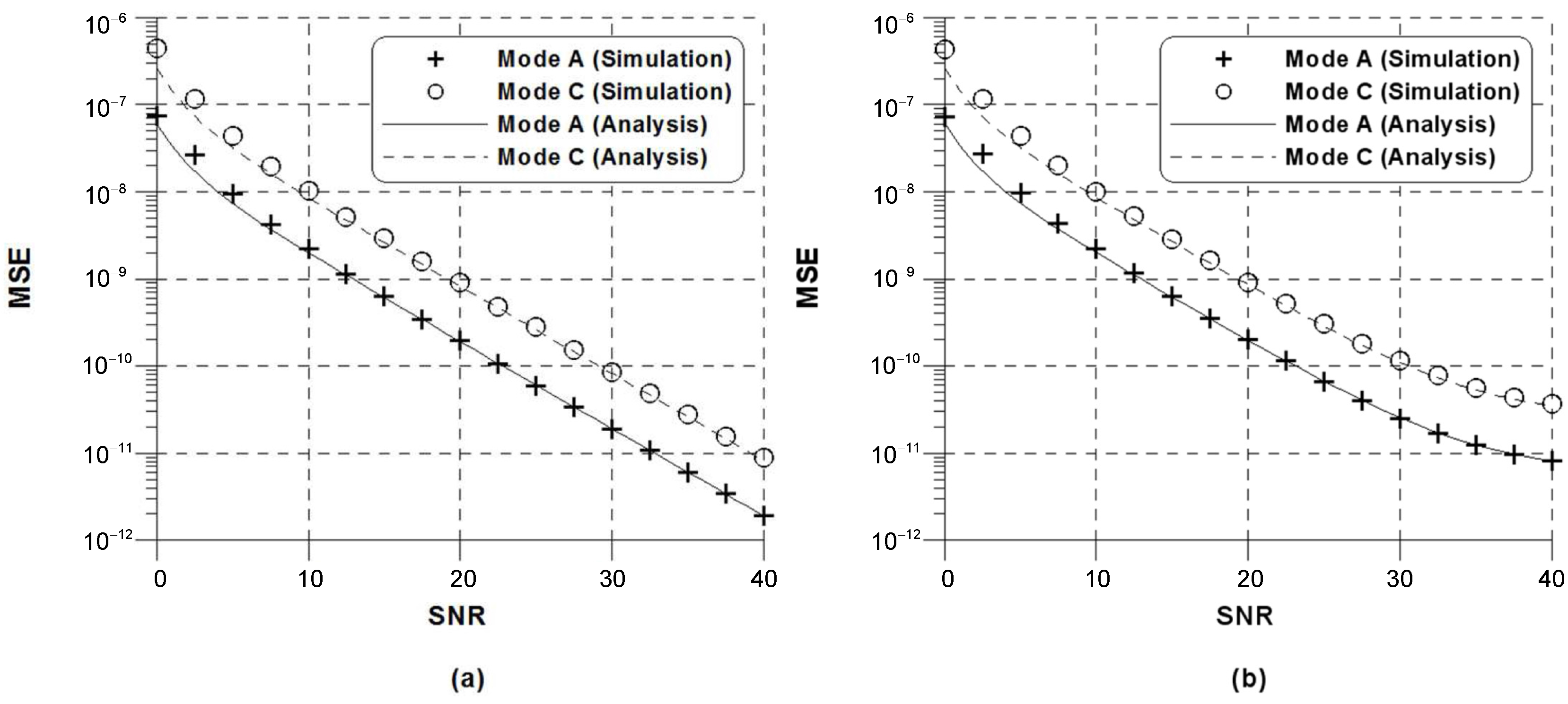
The MSE of the proposed estimator in CM1 is reported in Figure 2 for ppm. It is evident that the analytic curves in (32) are parallel to the simulated curves in CM1. It can be observed that the MSE of the proposed estimator is unbiased for relatively small . With the increase in , however, this does not hold at high SNR conditions, because the ICI is no longer negligible. For typical values of and , therefore, the ICI is negligible in comparison with the Gaussian noise under medium SNR conditions. It is also found that the DRM system is shown to contain sufficient information to perform synchronization. Interestingly, the different estimation performance can be observed according to the robustness mode-specific parameter as shown in Table 1. It is interesting to note that the proposed scheme (25) has no restriction to pilots similarly to (4).
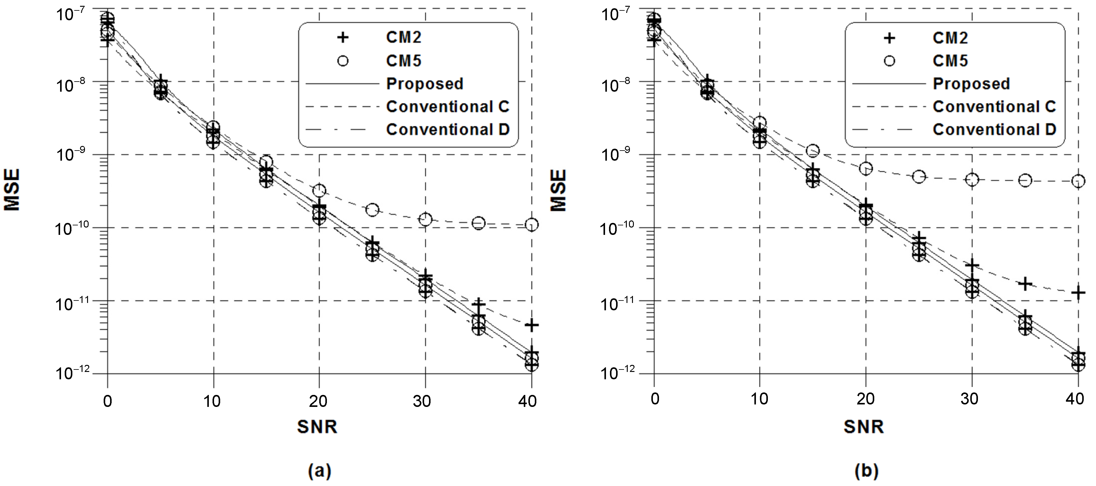
Figure 3 presents the comparison of MSE between the conventional scheme (14) and the proposed scheme when DRM mode A is used and . For the sake of fairness, is chosen for the conventional scheme (18), which uses the pilot symbols inserted into every OFDM symbol. In order to compute (19) and (20), a perfect knowledge of the CSI is assumed in the conventional scheme D. From the figure, it is observed that a slight performance degradation of the proposed scheme relative to the conventional scheme C in low SNR regions is observed, which is due to the SNR loss induced by the squaring of the complex conjugate operation in (22). As reported in [22,23], the conventional scheme C exhibits a non-negligible bias with an increase in SNR, which stems from the fact that its performance strongly is affected by the frequency selectivity of the channel and the value of SFO. Conversely, the performance of the proposed estimation scheme and the conventional scheme D is almost independent of the increased frequency selectivity and SFO. For a relatively small values of and , therefore, we conclude that the proposed SFO estimation scheme and the conventional scheme D are shown to be unbiased in the presence of the frequency selectivity. Under the assumption of perfect CSI, the MSE of the conventional scheme D is better than that of the proposed method at the cost of computational burdens. It can be seen that the number of flops used in the proposed estimation scheme is decreased by approximately 96% when compared with that used in the conventional scheme D.
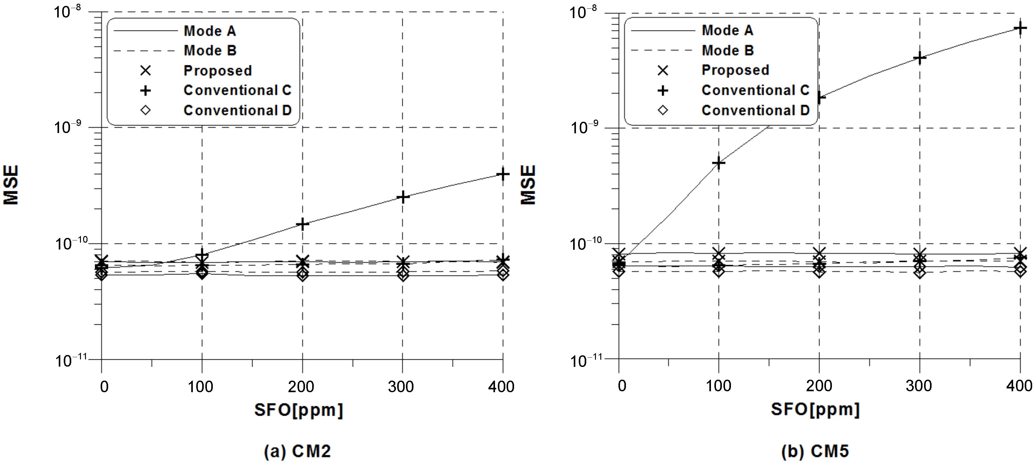
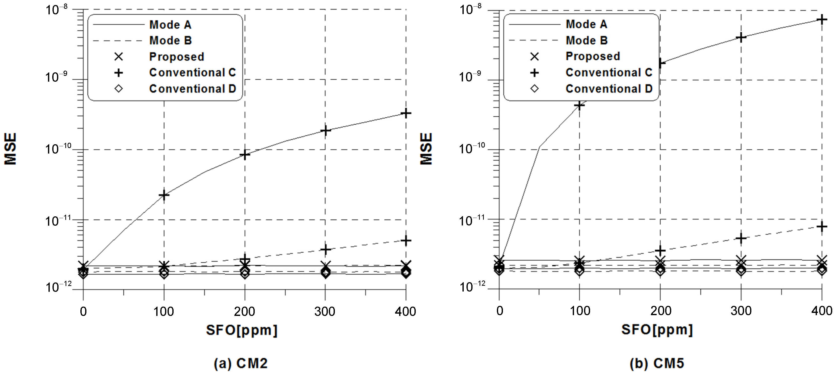
In Figure 4 and Figure 5, we compare MSE performance of the proposed scheme with the conventional schemes (14) and (18) under the same conditions as in Figure 3 when dB and dB, respectively. It is observed that the MSE of the conventional method C heavily depends on the amount of SFO, whereas the proposed scheme and the conventional scheme D exhibit a remarkable robustness against the SFO. Notably, we find that the amount of dependence on SFO in the conventional scheme C is different according to the DRM modes, which is inversely proportional to the ratio . This primarily comes from the fact that the conventional estimation scheme C experiences substantially less frequency selectivity as the ratio grows. Since SFO estimation is the focus here, the mobile speed is not taken into account. The DRM standard provides four different modes to cope with various transmission channel like delay spread and Doppler spread. In the case of analyzing the robustness of DRM modes against Doppler spread, the effect of mobile speed should be considered. As discussed in Figure 3, the MSE of the proposed scheme is slightly worse than that of the conventional scheme D, because the proposed scheme uses only two pilot symbols based on -symbol delay estimation. If the estimated CSI is used in the conventional scheme D, the performance degradation at low SNR regions can be observed due to channel estimation error, while the performance gap between the ideal and estimated cases is expected to be negligible with the increase in SNR. As for the conventional estimation scheme C and the proposed estimation scheme, they do not require any CSI.
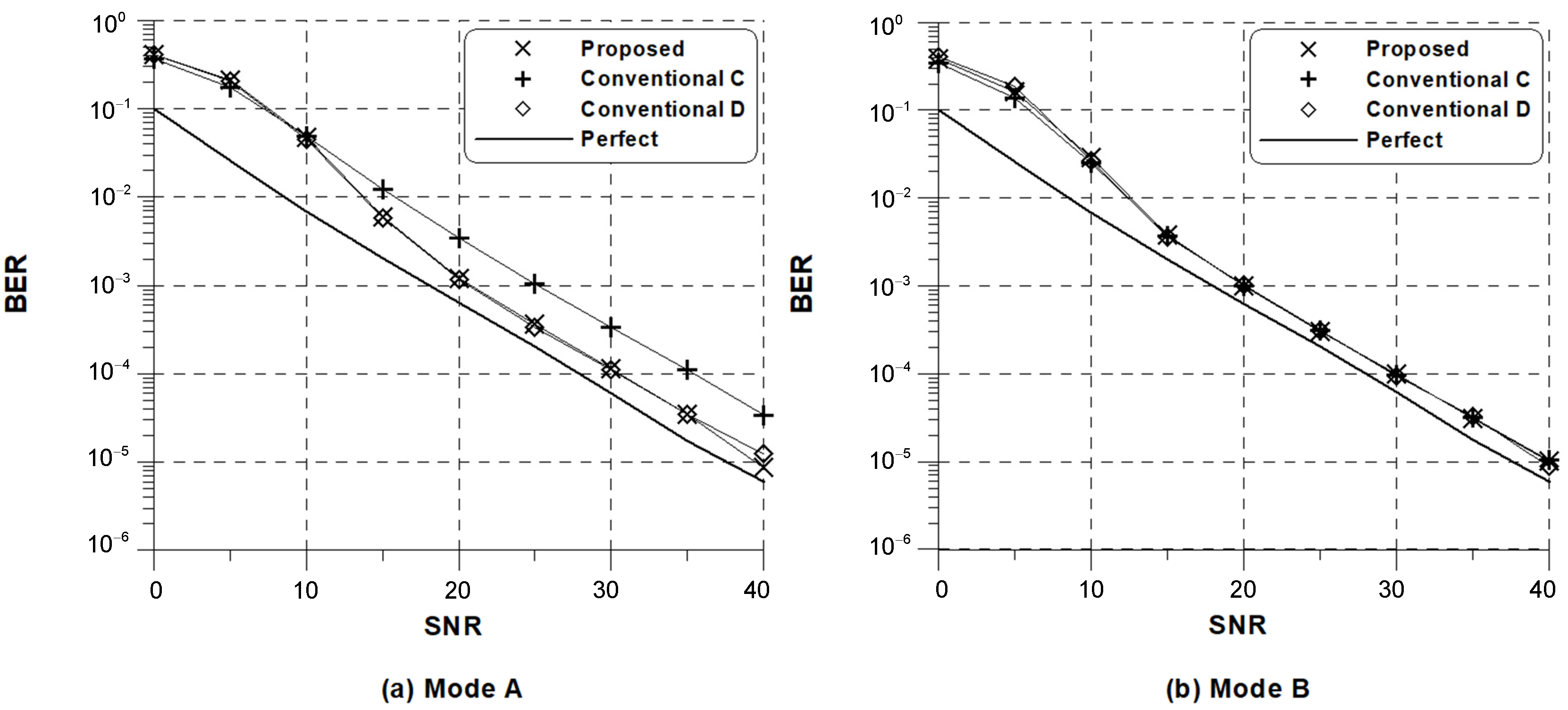
Figure 6 depicts the uncoded bit error rate (BER) obtained with the adoption of the conventional and proposed estimators followed by a one-tap frequency domain equalizer with perfect knowledge of CSI when , ppm, and CM5 is used. As a benchmark, the performance is compared with that of the perfectly synchronized DRM system. Here, the received OFDM symbols are directly compensated soon after SFO is estimated every symbol periods. One can observe a substantial performance gap between the BER with perfect synchronization and the BER with estimated SFO for all estimation schemes especially at low SNR values. As reported in Figure 3, a slight performance degradation of the proposed scheme at low SNR is also inherent in the case of BER. On the other hand, the fact that no irreducible floor is visible indicates that the proposed estimation scheme is capable of effectively mitigating the ICI induced by frequency errors with a reduced computational complexity.
6. Conclusions
In this paper, the problem of SFO estimation for the DRM system has been discussed, aiming at improving the robustness of SFO estimation in the presence of the frequency selective fading and designing its simple receiver structure. For verification of the SFO estimation schemes, the MSE expression of the conventional and proposed schemes was theoretically derived. We have demonstrated that the MSE analysis is fairly accurate, and the proposed estimation algorithm is shown to be not only robust but also unbiased in the presence of frequency selectivity of the channel.
Acknowledgments
This research was supported by Unmanned Vehicles Advanced Core Technology Research and Development Program through the National Research Foundation of Korea (NRF), Unmanned Vehicle Advanced Research Center (UVARC) funded by the Ministry of Science and ICT, the Republic of Korea (NRF-2017M1B3A2A01049997).
Author Contributions
Y.-A.J. and Y.-H.Y. designed and analyzed the proposed estimation algorithm. Y.-A.J. supplemented an algorithm for more high error performance and low complexity to make an proposed algorithm more competitive compared with existing algorithms. Y.-H.Y. gave feedbacks about an modified algorithm and all simulation results. Y.-A.J. and Y.-H.Y. wrote the paper jointly.
Conflicts of Interest
The authors declare no conflict of interest.
References
- ETSI Normalization Committee. Radio Broadcasting Systems: Digital Audio Broadcasting (DAB) to Mobile, Portable and Fixed Receivers; ETSI ETS 300 401; ETSI Normalization Committee: Sophia-Antipolis, France, 1995. [Google Scholar]
- ETSI Normalization Committee. Digital Radio Mondiale (DRM)—System Specification; ETSI ES 201 980 V3.1.1; ETSI Normalization Committee: Sophia-Antipolis, France, 2009. [Google Scholar]
- ETSI Normalization Committee. Digital Video Broadcasting (DVB): Frame Structure, Channel Coding and Modulation for Digital Terrestrial Television (DVB-T); ETSI ETS 300 744; ETSI Normalization Committee: Sophia-Antipolis, France, 1997. [Google Scholar]
- ETSI Normalization Committee. Frame Structure Channel Coding and Modulation for a Second Generation Digital Terrestrial Television Broadcasting System (DVB-T2); ETSI EN 302 755 V.1.4.1; ETSI Normalization Committee: Sophia-Antipolis, France, 2015. [Google Scholar]
- Institute of Electrical and Electronics Engineers (IEEE). Wireless LAN Medium Access Control (MAC) and Physical Layer (PHY) Specification: High-Speed Physical Layer in the 5 GHz Band; IEEE Std 802.11a; IEEE: Piscataway, NJ, USA, 1999. [Google Scholar]
- ETSI Normalization Committee. Physical Channels and Modulation (Release 10); 3GPP TS36.211 v10.0.0; ETSI: Sophia Antipolis, France, 2010. [Google Scholar]
- Guariglia, E. Entropy and Fractal Antennas. Entropy 2016, 18, 84. [Google Scholar] [CrossRef]
- Ortigueira, M.D. A coherent approach to non-integer order derivatives. Signal Process. 2006, 10, 2505–2515. [Google Scholar] [CrossRef]
- Li, C.; Dao, X.; Guo, P. Fractional derivatives in complex planes. Nonlinear Anal. Theory Methods Appl. 2009, 71, 1857–1869. [Google Scholar] [CrossRef]
- Cheng, Y.; Ming, Y. Integer frequency offset algorithm for digital radio mondiale system. J. Commun. 2013, 8, 572–578. [Google Scholar]
- Kwon, K.; Seo, J.; Cho, Y.; Paik, J. Integer frequency offset estimation by pilot subset selection for OFDM system with CDD. Electron. Lett. 2012, 48, 1434–1435. [Google Scholar] [CrossRef]
- Fischer, V.; Kurpiers, A. Frequency synchronization strategy for a PC-based DRM receiver. In Proceedings of the 7th International OFDM Workshop, Hamburg, Germany, 10–11 September 2002. [Google Scholar]
- Shin, W.J.; Seo, J.W.; You, Y.H. MSE analysis of sampling frequency offset estimation scheme for OFDM-based digital radio mondiale (DRM) systems. Wirel. Pers. Commun. 2013, 71, 1271–1281. [Google Scholar] [CrossRef]
- Shim, E.S.; Lee, K.T.; Kwon, K.W.; You, Y.H. Synchronization receiver design for OFDM-based FM broadcasting systems. Wirel. Pers. Commun. 2011, 58, 355–367. [Google Scholar] [CrossRef]
- Henkel, M.; Schroer, W. Pilot based synchronization strategy for a coherent OFDM receiver. In Proceedings of the Wireless Communications and Networking Conference, Kowloon, China, 11–15 March 2007; pp. 1982–1986. [Google Scholar]
- Kurpiers, A.; Fischer, V. Open-source implementation of a digital radio mondiale (DRM) receiver. In Proceedings of the 9th International Conference on HF Radio Systems and Techniques, Bath, UK, 23–26 June 2003; pp. 86–90. [Google Scholar]
- Zhou, H.; Huang, Y.F. A maximum likelihood fine timing estimation for wireless OFDM systems. IEEE Trans. Broadcast. 2009, 55, 31–41. [Google Scholar] [CrossRef]
- Tsai, P.Y.; Kang, H.Y.; Chieuh, T.D. Joint weighted least-squares estimation of carrier-frequency and timing offset for OFDM systems over multipath fading channels. IEEE Trans. Veh. Technol. 2005, 54, 211–223. [Google Scholar] [CrossRef]
- Chin, W.L. ML estimation of timing and frequency offsets using distinctive correlation characteristics of OFDM signals over dispersive fading channels. IEEE Trans. Veh. Technol. 2011, 60, 444–456. [Google Scholar] [CrossRef]
- Speth, M.; Fechtel, S.A.; Fock, G.; Meyr, H. Optimum receiver design for wireless broad-band systems using OFDM-Part I. IEEE Trans. Commun. 1999, 47, 1668–1677. [Google Scholar] [CrossRef]
- Oberli, C. ML-based tracking algorithms for MIMO-OFDM. IEEE Trans. Wirel. Commun. 2007, 6, 2630–2639. [Google Scholar] [CrossRef]
- Morelli, M.; Moretti, M. Fine carrier and sampling frequency synchronization in OFDM systems. IEEE Trans. Wirel. Commun. 2010, 9, 1514–1524. [Google Scholar] [CrossRef]
- Shi, K.; Serpedin, E.; Ciblat, P. Decision-directed fine synchronization in OFDM systems. IEEE Trans. Commun. 2005, 53, 408–412. [Google Scholar] [CrossRef]
- Fowler, M.L. Phase-based frequency estimation: A review. Digit. Signal Process. 2002, 12, 590–615. [Google Scholar] [CrossRef]
- Golub, G.H.; Van Loan, C.F. Matrix Computations; The Johns Hopkins University Press: Baltimore, MD, USA, 1996. [Google Scholar]
Figure 1.
Mean square error (MSE) of the conventional frequency estimators in channel model (CM)1: (1) lines-analysis; (2) symbols-simulation.
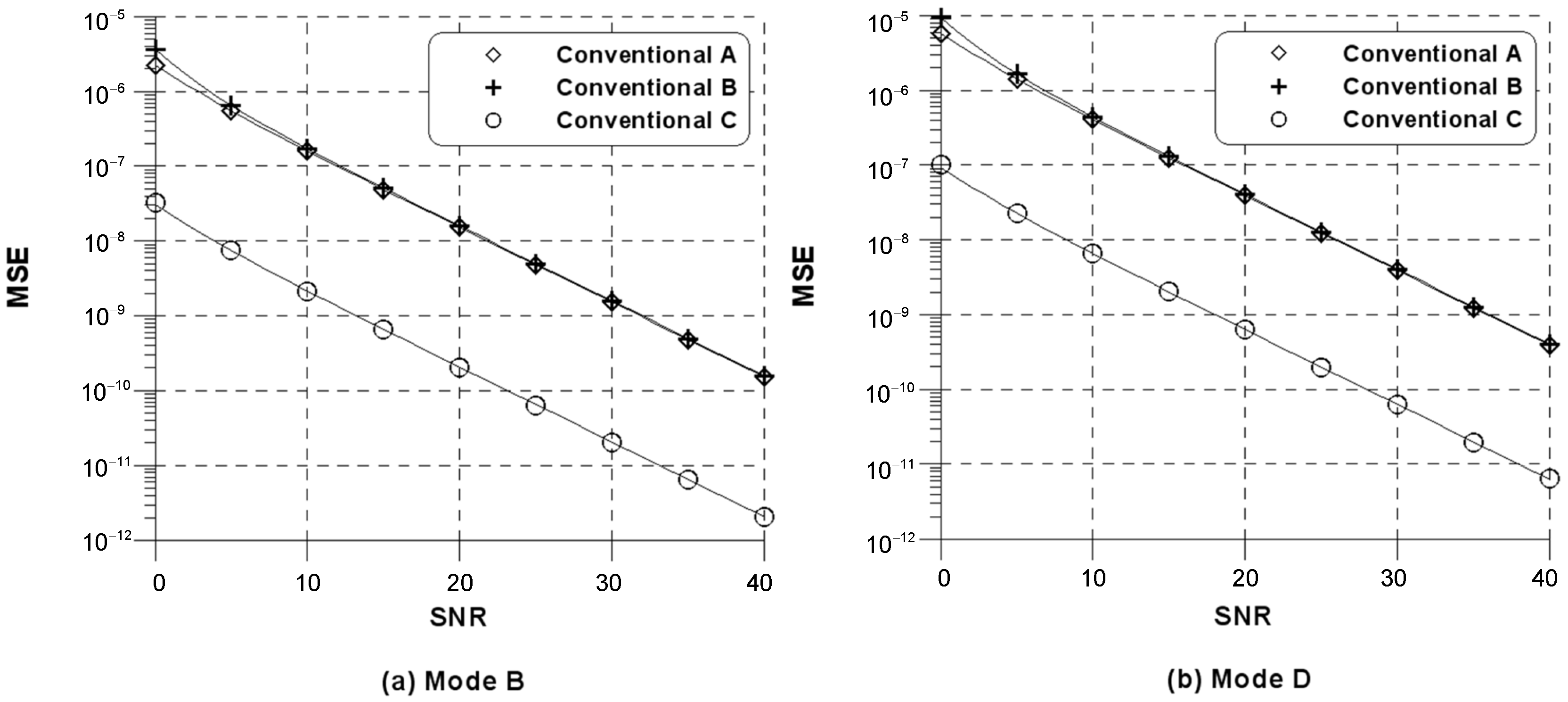
Figure 2.
MSE of the proposed frequency estimator in CM1: (a) ; (b) .

Figure 3.
MSE of the conventional and proposed frequency estimators in DRM mode A: (a) ppm; (b) ppm.
Figure 3.
MSE of the conventional and proposed frequency estimators in DRM mode A: (a) ppm; (b) ppm.

Figure 4.
MSE of the conventional and proposed frequency estimators versus sampling frequency offset (SFO) for DRM modes A and B when signal-to-noise ratio (SNR) = 25 dB.
Figure 4.
MSE of the conventional and proposed frequency estimators versus sampling frequency offset (SFO) for DRM modes A and B when signal-to-noise ratio (SNR) = 25 dB.

Figure 5.
MSE of the conventional and proposed frequency estimators versus SFO for DRM modes A and B when SNR = 40 dB.
Figure 5.
MSE of the conventional and proposed frequency estimators versus SFO for DRM modes A and B when SNR = 40 dB.

Figure 6.
Bit error rate (BER) performance of the conventional and proposed frequency estimators in CM5.
Figure 6.
Bit error rate (BER) performance of the conventional and proposed frequency estimators in CM5.


Table 1.
Main parameters in Digital Radio Mondiale (DRM) modes.
| Mode A | Mode B | Mode C | Mode D | |
|---|---|---|---|---|
| N | 288 | 256 | 176 | 112 |
| 32 | 64 | 64 | 88 | |
| 12 | 34 | 36 | 28 | |
| 5 | 3 | 2 | 3 |
Table 2.
Main parameters in DRM channel models.
| CM1 | CM2 | CM3 | CM4 | CM5 | CM6 | |
|---|---|---|---|---|---|---|
| Number of path | 1 | 2 | 4 | 2 | 2 | 4 |
| Maximum delay spread (ms) | 0 | 1 | 2.2 | 2 | 4 | 6 |
| Maximum Doppler spread (Hz) | 0 | 0.1 | 2 | 1 | 2 | 7.2 |
© 2018 by the authors. Licensee MDPI, Basel, Switzerland. This article is an open access article distributed under the terms and conditions of the Creative Commons Attribution (CC BY) license (http://creativecommons.org/licenses/by/4.0/).
Share and Cite
MDPI and ACS Style
Jung, Y.-A.; You, Y.-H. Robust Sampling Frequency Offset Estimation for OFDM over Frequency Selective Fading Channels. Appl. Sci. 2018, 8, 197. https://doi.org/10.3390/app8020197
AMA Style
Jung Y-A, You Y-H. Robust Sampling Frequency Offset Estimation for OFDM over Frequency Selective Fading Channels. Applied Sciences. 2018; 8(2):197. https://doi.org/10.3390/app8020197
Chicago/Turabian StyleJung, Yong-An, and Young-Hwan You. 2018. "Robust Sampling Frequency Offset Estimation for OFDM over Frequency Selective Fading Channels" Applied Sciences 8, no. 2: 197. https://doi.org/10.3390/app8020197
Note that from the first issue of 2016, this journal uses article numbers instead of page numbers. See further details here.