Attosecond Pulse Shaping by Multilayer Mirrors


1
Fakultät für Physik, Ludwig-Maximilians-Universität München, Am Couloumbwall 1, 85748 Garching, Germany
2
Max-Planck-Institut für Quantenoptik, Hans-Kopfermann Strasse 1, 85748 Garching, Germany
3
Department of Chemistry, University of California, Berkeley, CA 94720, USA
*
Author to whom correspondence should be addressed.
†
These authors contributed equally to this work.
Appl. Sci. 2018, 8(12), 2503; https://doi.org/10.3390/app8122503
Submission received: 14 November 2018
/
Revised: 28 November 2018
/
Accepted: 29 November 2018
/
Published: 5 December 2018
(This article belongs to the Special Issue Advanced EUV and X-Ray Optics)
Abstract
:The emerging research field of attosecond science allows for the temporal investigation of one of the fastest dynamics in nature: electron dynamics in matter. These dynamics are responsible for chemical and biological processes, and the ability to understand and control them opens a new door of fundamental science, with the possibility to influence all lives if medical issues can thereby be addressed. Multilayer optics are key elements in attosecond experiments; they are used to tailor attosecond pulses with well-defined characteristics to facilitate detailed and accurate insight into processes, e.g., photoemission, Auger decay, or (core-) excitons. Based on the investigations and research efforts from the past several years, multilayer mirrors today are routinely used optical elements in attosecond beamlines. As a consequence, the generation of ultrashort pulses, combined with their dispersion control, has proceeded from the femtosecond range in the visible/infrared spectra to the attosecond range, covering the extreme ultraviolet and soft X-ray photon range up to the water window. This article reviews our work on multilayer optics over the past several years, as well as the impact from other research groups, to reflect on the scientific background of their nowadays routine use in attosecond physics.
1. Introduction
Multilayer-based optics have been developed into well-established optical components for steering [1], focusing [2], polarizing [3] and spectral filtering [4] of extreme ultraviolet (EUV)/soft X-ray radiation since its first description by Spiller in 1976 [5].
Their significant advantage compared with single-surface grazing incidence optics (working in total external reflection) lies in an increased glancing angle (even up to near-normal incidence), larger collection angle, better imaging performance (due to decreased astigmatism), and tailored spectral filtering. However, in many cases, multilayer reflectors do not reach the high reflectance values of grazing incidence mirrors and are limited to peak reflectances slightly above 70% at best, mainly due to absorption and scattering losses [6].
Due to remarkable improvements in various deposition techniques, such as electron beam evaporation [7,8], magnetron [9,10,11] and ion beam sputtering [12,13,14], or pulsed laser deposition [15,16,17], numerous multilayer properties can be realized. Nowadays, multilayers consist of various metal, semiconductor, or dielectric materials with layer thicknesses ranging down to less than 1 nm, layer numbers of many hundreds to thousands, and layer precisions in terms of thickness and interface accuracies on an atomic length scale (0.1 nm).
Most multilayer optics development in the past was directed toward improved reflectivities for various multilayer material combinations and various photon energies from extended ultraviolet (EUV) to the soft X-ray regime. Such multilayer optics have been employed as imaging devices in solar astronomy [18], EUV lithography [19] and microscopy [20], plasma diagnostics [21], synchrotron radiation optics [22], and many more. Ultrashort soft X-ray radiation bursts with a few femtoseconds ( s) to attosecond ( s) pulse durations have become accessible over the past few years. This was possible due to advanced laser technology in high harmonic generation (HHG) [23] or advanced electron accelerator technology in free electron lasers (FEL) [24]. The application of multilayer optics to the formation and handling of these pulses has only recently been discussed in the literature; however, it is gaining increasing attention from the scientific community.
This article aims to review the status of (our) multilayer attosecond optics development in these fields.
1.1. Attosecond Pulses (Isolated and Pulsed Trains)
Attosecond pulses of soft X-ray radiation bursts, either as isolated single pulses (where one attosecond pulse is generated by one laser pulse) or as pulse trains (where multiple approximately equal-spaced attosecond pulses are generated by one laser pulse), have become possible by the invention of femtosecond laser amplifiers. These amplifiers deliver few-cycle laser pulses with a controlled electric field under the pulse envelope (carrier envelope offset phase stabilization) and their frequency is converted in HHG. They constitute, as of today, one of the shortest electromagnetic pulses in time and provide the basis for time-resolved experiments. These experiments characterize the temporal dynamics of electron wave packets in atoms, molecules, or even condensed matter systems.
While HHG is delivering extremely short pulses in time, its very small conversion efficiency limits the applicability currently to the EUV (lower soft X-ray) range and to very low pulse energies.
Pulses of higher photon energy in the soft to hard X-ray range and much larger pulse energies can be delivered by free-electron X-ray laser sources. However, their controlled pulse duration is currently still limited to some tens of femtoseconds. Very recent experiments performed at LCLS (Linac Coherent Light Source) might have developed an experimental way to further compress such pulses into a few femtoseconds, or even sub-femtosecond regime [25], which might then outperform current HHG sources in the foreseen future.
However, what both sources have in common is the generation of broad bandwidth radiation at short spectral wavelengths. This requires proper handling of the spectral amplitude, as well as of the spectral phase by subsequent optics components. Multilayer optics are proven to play a dominant role in controlling the amplitude and phase of the reflected radiation, thus providing a powerful toolbox for temporal pulse shaping. These properties are described in the following article.
1.2. HHG as Major/Only Attosecond Pulse Source
There are many publications on the generation of attosecond pulses by HHG which deliver a very intuitive theoretical description [26] of this process, as well as describe the required experimental setups [27] and generated radiation spectra and pulses [28].
The process of HHG in atoms and molecules is theoretically best described by the three-step model of Corkum [29]. The model separates the process into different steps. It starts with laser-field induced tunnel ionization of electrons during a fraction of a laser period. This step is followed by the acceleration of the free charges in the ponderomotive laser field. Finally, the rescattering of the returning electrons with their parent cores occurs.
It is important to note that this process delivers a coherent (spatially and temporally) radiation spectrum with multiple odd overtones (harmonics) of the driving laser frequency. The generated spectrum ranges from the laser’s fundamental wavelength (with a Ti:sapphire laser usually in the near-infrared (NIR) at 780 nm) over the strongly modulated plateau region toward the weakly modulated cut-off regime. The cut-off regime constitutes the shortest HHG wavelengths.
The spectral position of the HHG cut-off is determined by the laser’s pulse intensity I and carrier frequency , as well as the ionization potential of the target atom, and is given by the following formula:
with the ponderomotive potential of the laser:
The forming of single isolated attosecond pulses from such broadband HHG radiation spectra is performed by filtering out the shortest-wavelength part of the HHG spectrum in the cut-off regime. This is typically achieved by transparent filter foils, grazing incidence or multilayer reflectors, or a combination of those elements.
Thin-film filters and grazing incidence optics are not very versatile for tailor-made spectral filtering and spectral phase manipulation. In contrast, multilayer optics, such as those described herein, allow for a wide range of tailor-made spectra and phases, thus providing the best flexibility for temporal pulse shaping.
1.3. What Is It Good for? The Applications
Coherent EUV pulses from HHG and their optics components find a wide range of applications in experiments. Some experiments make use of the almost perfect coherence of the generated radiation, such as in experiments on EUV interferometry [30]; HHG microscopy, such as coherent diffractive imaging (CDI) [4]; or the generation of EUV frequency combs for advanced metrology [31].
However, the majority of applications of HHG radiation utilize the attosecond temporal structure. For example, pump-probe experiments on electron streaking are providing insights into the electron wave packet dynamics in atoms [32] and molecules [33], as well as giving new insights into the photoemission process from solid surfaces [34] or nanostructures [35].
While most of the experiments utilize single isolated attosecond pulses, as they are required for clean electron streaking experiments, the recent use of attosecond pulse trains has been also established in RABBITT (reconstruction of attosecond beating by two-photon-transitions) measurements. RABBITT might provide a path to attosecond angle-resolved photoemission spectroscopy (ARPES) characterization of solid surfaces in the near future [36].
It is important to note that all those different experiments impose different requirements on the inevitable spectral filtering of the HHG spectrum by the EUV optical components. This can in many cases be best achieved by proper multilayer reflectors.
2. Simulations of Multilayer Systems: Their Theoretical Optical Performance
A self-written multilayer Fresnel code algorithm (written with the software MATLAB (version 7.8)) is used for reflectivity and transmission calculations. Either the overall reflectivity (mirror) or the transmission (polarizer, filter) is calculated, together with the relevant phase based on the multiple interface reflections and transmissions. The code utilizes the tabulated atomic scattering factor values from Henke and Gullikson [37]. Values above 30 eV are used to calculate the dispersion and the extinction necessary for the Fresnel equations. Realistic imperfect interfaces, top layer oxidation, or interlayer formation like molybdenum silicide [38] are considered to be the stack design demands. We can thus identify various parameters which are used as input for the simulations. These parameters are either tabulated from former characterization measurements or theoretical studies or should be extracted from one’s own research studies and different characterization or analysis methods:
- Top layer oxidation. Analysis methods like interface roughness and, additionally, spectral ellipsometry. The thickness loss of the top layer material, as well as the thickness of the native grown oxide layer, should be determined. It is important since those two layers are responsible for a small aperiodicity within the stack, as well as being the first layers the radiation penetrates through—a very important fact in the case of EUV radiation.
- Interlayer formation. Analysis methods similar to interface roughness.
The self-written code is used for simulating the optical performance of periodic multilayer systems or of already calculated aperiodic designs. The calculations of aperiodic designs were previously realized with the software Optilayer (version 8.85). It is based on a Fresnel code coupled to a ’needle optimization’ algorithm [44,45]. This software is mainly used for the optimization of (aperiodic) chirped mirrors in combination with the self-written Fresnel code. A properly chosen start design is the most important prerequisite for a reasonable optimization. Usually, one starts with a periodic multilayer structure which already consists of the material combination best suited for the targeted spectral range. One adjusts the layer thicknesses to the central energy E of interest at a certain angle of incidence. The period number N of the start design is chosen according to the required spectral bandwidth and is estimated by:
Finally, one or more target functions are defined for the algorithm for which the start design should be optimized. Optimizations can, for instance, include a spectrally broader mirror reflectivity, a higher peak reflectivity, or, in case of chirped mirrors, an optimized spectral phase. The optimized spectral phase is being realized by aperiodic layers which introduce a group delay dispersion (GDD), in contrast to a periodic system having a flat phase. The group delay dispersion is the negative second derivative of the spectral phase, (). The needle optimization algorithm [44] takes the periodic design and inserts small (needle-like) additional layers at certain positions in the stack. This is defined by the best benefit for the merit function (MF). The thicknesses of these layers are consecutively decreased or increased until their best thickness values are achieved. Each optimization procedure consists of a certain number of iterations in which the current design is changed by random walk within user-defined limits. The merit function is used to quantify the quality of a design . It includes weights (which must be predefined) that define the importance of the individual target function :
The figure-of-merit function further rules whether the modern design is taken as the start design for the next iteration step or not. As a result, every calculated design is a trade-off between different target functions and is a consequence of the start design. Finally, the implementability of a final design is checked and converted into deposition times using a self-written Fresnel-code algorithm. A realistic Névot–Croce roughness, interlayer formation, and structural changes yielding thickness losses (based on diffusion) are included and compensated for by the code. Both the temporal and spectral characteristics of the pulse are analyzed, including both the source and the filter characteristics. This enables the comparison of the most realistic pulse simulation with the experimental constraints. Due to the needle optimization procedure, ultrathin layers are either eliminated or broadened to a realizable value of at least 1 nm. If the final design does not fulfill the previously stated requirements, an innovative design optimization is necessary. This can be realized with either a better start design or freshly designed target points and weights. This procedure is used for aperiodic multilayer mirrors for shaping the GDD of attosecond pulses. Two important parameters for the reflectivity performance of an EUV multilayer mirror are polarization and angle of incidence, which are included in the simulation and optimization. The reflectivity for s- and p-polarization is the same at normal incidence. In the case of s-polarization, the reflectivity continuously increases with increasing normal incidence angle and approaches total reflection above the critical angle (in the EUV, close to normal incidence). In the case of p-polarization, the reflectivity decreases with increasing normal incidence angle and approaches zero at the Brewster angle (in the EUV, around ). The continuous increment of the reflectivity afterward also leads to total reflection above the critical angle. A detailed description can be found in [5].
3. Fabrication of Multilayer Coatings
Various deposition techniques are used to realize advanced multilayer coatings. Every technique has advantages and disadvantages, and one should evaluate the coating priorities according to numerous criteria, such as overall cost, deposition speed, layer density (which is directly connected to damage thresholds), thickness accuracy, number of target materials, availability of target materials, vacuum requirements, in-situ characterization techniques, and coating homogeneity, to name only some of them. Nowadays, the following techniques are used for the realization of multilayer coatings:
- Electron beam physical vapor deposition (EBPVD) [7,8] is a form of physical vapor deposition in which a target material anode is bombarded with an electron beam. The electron beam arises from a charged tungsten filament under high vacuum. The electron beam causes atoms from the target to transform into the gaseous phase. These atoms then precipitate into solid form, coating everything in the vacuum chamber (within line of sight) with a thin layer of the anode material.
- Magnetron sputtering [9,10,11] is a plasma vapor deposition (PVD) process in which a plasma is created. The positively charged ions from the plasma are accelerated by an electrical field superimposed on the negatively charged electrode or ’target’. The positive ions are accelerated by potentials ranging from a few hundred to a few thousand electron volts and strike the negative electrode with sufficient force to dislodge and eject atoms from the target material. These atoms will be ejected in a typical line-of-sight cosine distribution from the face of the target and will condense on (substrate) surfaces that are placed in proximity to the magnetron sputtering cathode.
- A (dual) ion beam deposition (D-IBD) [12,13,14] apparatus typically consists of an ion source, ion optics, and the deposition target. Optionally, a mass analyzer can be incorporated. In the ion source, materials in the form of a gas, an evaporated solid, or a solution (liquid) are ionized. The ions are then accelerated, focused, or deflected using high voltages or magnetic fields. Optional deceleration at the substrate can be employed to define the deposition energy. This energy usually ranges from a few to a few thousand electron volts. At low energy, molecular ion beams are deposited intact (soft landing), while, at a high deposition energy, molecular ions fragment, and atomic ions penetrate further into the material. This process is known as ion implantation. The ion beam current, which is a quantitative measure for the deposited amount of material, can be monitored during the deposition process.
- Pulsed laser deposition (PLD) [15,16,17] is a physical vapor deposition technique where a high-power pulsed laser beam is focused inside a vacuum chamber to strike the target material that is to be deposited. This material is vaporized from the target in a plasma plume, which deposits the material as a thin film on a substrate. This process can occur in ultrahigh vacuum or in the presence of a background gas, such as oxygen. Oxygen is commonly used when depositing oxides to fully oxygenate the deposited films.
- Metalorganic vapor phase epitaxy (MOVPE), also known as organometallic vapor phase epitaxy (OMVPE) or metalorganic chemical vapor deposition (MOCVD) [46,47], is a chemical vapor deposition method used to produce single or polycrystalline thin films. It is a highly complex process for growing crystalline layers to create complex semiconductor multilayer structures. In contrast to molecular beam epitaxy (MBE), the growth of crystals is by chemical reaction and not by physical deposition. This takes place not in a vacuum but from the gas phase at moderate pressures (10–760 Torr). As such, this technique is preferred for the formation of devices incorporating thermodynamically metastable alloys. It has become a major process in the manufacture of optoelectronics.
4. Achieved Results and Examples of Multilayer Mirrors for Attosecond Pulses
This section focuses on results which have been achieved so far in different spectral ranges. Ever shorter isolated attosecond pulses enable experimental access to the absolute or relative timing of electronic processes with never-achieved temporal resolution [26,48,49]. The filtering, reflection, and shaping of attosecond pulses require phase-correct broadband optics. Especially in normal incidence setups, the question of the shortest possible attosecond pulses is thus directly connected to the availability of appropriate optics, namely, EUV multilayer mirrors and filters. One can estimate the bandwidth of an N-period multilayer stack with central energy E from Equation (3): . An interference coating consists of at least two periods (); thus, in principle, the maximum bandwidth of a periodic multilayer mirror is about half of its central energy. Higher central energies relax the constraints on the bandwidth of optics and thus enable shorter reflected pulses, but they usually suffer from lower reflectivity.
4.1. A Normal Incidence Broadband 30–60 eV Mirror
Many attosecond experiments are performed in the spectral range between 30 and 60 eV, which is easy to access with high harmonic sources [50,51,52]. The shortest attosecond pulses in this spectral range could be generated by polarization gating. Sansone et al. realized 130 as long pulses around 40 eV [51]. This and other experiments may benefit from broadband normal incidence EUV optics suitable for attosecond beam guidance and focusing. An aperiodic broadband mirror (/Mo/Si) reflecting between 35 and 50 eV with a reflectivity up to 20% was designed and published by Morlens et al. [53]. In the following section, we present a periodic Si/Sc mirror centered at nearly the same central energy of ≈40 eV with comparable bandwidth to Morlens’ mirror but with periodic layers; it is thus an almost flat phase for a close to dispersion free reflection. This allows for spectrally filtering the high harmonics cut-off from krypton, offering isolated attosecond pulses below 200 as. Its design is chosen such that the high single interface reflectivity of Si and Sc is extended by an appropriate quarter-wave design to a bandwidth of more than 20 eV. Until now, Si/Sc multilayers have mainly been used at energies between 25 and 35 eV [54], just below the Sc -edge. Above this energy, both Si and Sc are highly absorbing, and the number of contributing periods in Si/Sc multilayers is very limited. The normal incidence reflectivity saturates between 35 and 45 eV for only ≈5 periods. The relatively high reflectivity between 5 and 7% is mostly independent of the mirror design due to a high single interface reflectivity of about 2%. This property has been utilized for the design of the following ultra-broadband mirror. Its design is chosen such that the already high Si, Sc reflectivity is extended to the high-energy side for a larger overall bandwidth. A 10-period Si/Sc coating with a period thickness of 14 nm (for a central energy of ≈50 eV) was chosen (Figure 1b).
The mirror’s designed and measured reflectivity are plotted together with the calculated phase in Figure 1a. A comparison with simulations reveals a maximum thickness error of below 0.8%, which is directly convertible to the shift in central energy. The measured EUV reflectivity confirms a successful implementation, a bandwidth of more than 20 eV, and a reflectivity between 5 and 15%. Simulations show that this mirror is capable of supporting the reflection of Fourier-limited 165 as long pulses that correspond to only 1.7 EUV field oscillations at 42 eV central energy (Figure 1c). This mirror thus allows for the phase-correct reflection of sub-2 cycle EUV pulses and is therefore at the possible duration limit at this energy.
4.2. Short Pulses in the 60–100 eV Range
Shorter pulses require even more bandwidth and thus necessarily higher central energies. The development of ultra-broad high harmonic cut-off spectra with sufficiently high photon flux in the spectral range (between 60 and 100 eV) and the availability of appropriate thin metal filters and broadband high-reflectivity multilayer optics suggest this energy range for the generation of ever shorter ultrashort pulses. The high harmonic-generated EUV cut-off spectrum at about 100 eV matches the high reflectivity spectral band of Mo/Si multilayer mirrors; this material combination was thus chosen. The generation of 80 as long pulses [55] requires at least a 25 eV (full-width-at-half-maximum (FWHM)) bandwidth (for a Gaussian spectrum) and is given by the multiplication of both the spectrum of the optics and the high harmonic spectrum from which the single pulse is being filtered. As will be presented in the following paragraph, this requires an HHG spectrum which exceeds the chirp-free cut-off region, ranging in the lower energy plateau region, which is known to be positively chirped. This phase behavior (positive chirp at low energies, negligible chirp at high energies) exactly opposes that of a thin zirconium (Zr) filter, which was used in this experimental setup anyway to filter the laser light from the EUV propagation path. As the filter indispensably compensates for most of the HHG chirp, a chirp-less but broadband attosecond mirror is required. The penetration depth and thus the maximum number of usable bi-layers is limited by the attosecond pulse length. A four-layer Mo/Si EUV coating centered at 70 eV, with a bandwidth of 32 eV (FWHM), was designed for the coating of the inner part of the double mirror (Figure 2b). Its reflectivity was measured (green stars in Figure 2a) and is in good agreement with the simulations. Figure 2 concludes the spectral (panel a) and the temporal (panel c) characteristics of this bandpass.
Simulations reveal that the mirror alone supports the reflection of nearly Fourier-limited pulses of 64 as (Fourier-limit of the mirror: 63 as) calculated from the simulated spectrum (black line in Figure 2c) and the phase (red dash-dotted line). The effective bandpass bandwidth is experimentally limited by the transmission of the Zr filter, which is required for suppression of the infrared laser light and for tuning the spectral phase. Different filter thicknesses (150, 300, and 450 nm) allow for some tunability of the GDD for the sake of reducing the effective bandwidth (the peak of the multiplied spectrum, plotted by the blue dashed line, is shifted toward higher energies). It turned out that the combination of the mirror with a 300 nm Zr filter (yellow line, Figure 2a) compresses the incoming pulse to almost its Fourier-limit. The goodness of the perfect interplay between the spectral phase of the bandpass and that of the high harmonic source becomes more obvious when one compares the temporal structure of the bandpass (blue dashed line in Figure 2c) with its Fourier-limit (light green dash-dotted line). The bandpass has a Fourier-limit of 80 as, and its temporal structure reveals 90 as, including the phase (pulse broadening can be almost entirely related to the phase of the filter). The final pulse-length of 80 as is thus at exactly the Fourier-limit of the bandpass. Please note here that the final pulse is a convolution of the bandpass and the incoming pulse. The high harmonic intensity decreases at higher energies in the cut-off range and yields a slight downshift and a slight broadening of the bandpass spectrum. This experiment resulted in the generation of light flashes of no more than 80 as and was published by Goulielmakis et al. in Science [32].
4.3. Above the Silicon L-Edge in the 100–150 eV Photon Range
Various multilayer mirrors have been realized for attosecond pulses above 100 eV [56,57], going from the EUV spectral range to the soft X-ray range, for addressing more core states of numerous elements. The next section describes, as examples, attosecond dispersion control by multilayer mirrors based on Hofstetter et al. [58], as well as a chromium/scandium (Cr/Sc) mirror designed for a central energy of around 145 eV and reflecting attosecond pulses on the order of 600 as. The latter experiment was realized at a central energy which was at that time 27 eV higher than the recent energy limit in table-top attosecond pump studies [34]. Attosecond dispersion control is used as a synonym for controlling the second derivative of the spectral phase of an attosecond pulse, its group delay dispersion. This control offers the possibility for pulse compression down to the Fourier-limit.
4.3.1. Attosecond Dispersion Control by Multilayer Mirrors above 100 eV
Specially designed aperiodic (binary or ternary multilayers) EUV mirrors allow for a large degree of freedom in shaping the EUV pulse characteristics by the reflection of those mirrors [59]. So far, multilayer mirrors in attosecond physics applications have been used as bandpass reflectors to preserve the spectral phase of the attosecond pulse that is defined in the generation process and by the dispersion characteristics of all EUV optical elements passed by the pulse. In this work, we demonstrate how specially designed non-periodic multilayer EUV mirrors furnish attosecond technology with the ability to control the spectral phase in addition to the spectral intensity of attosecond pulses. This offers a great degree of freedom in influencing the EUV pulse characteristics, such as the pulse shape, duration, frequency sweep, and central wavelength.
To prove the validity of the concept for precision chirp control of attosecond EUV pulses, three multilayer mirrors exhibiting distinctly different GDD but similar reflectivity characteristics were developed [58]. Optimized for an angle of incidence of , they exhibit high reflectivity within the range of 100–130 eV with a comparable FWHM energy bandwidth of = 11–13 eV and peaking at different central energies within the range of 107–122 eV.
The multilayer designs were calculated and optimized by a Fresnel equation thin film code coupled to a needle optimization algorithm [44]. The mirrors were designed such that the GDD is almost maximum and mostly linear within the final attosecond pulse spectrum. Small shifts of the mirror spectrum due to the thin metal filter or the shape of the high harmonic cut-off spectrum were estimated and considered in the designs. The calculated designs were optimized for additional suppressed reflectivity contributions in the near vicinity of the main Bragg peak and were tested for stability against small layer thickness deviations. The final multilayer coating designs are displayed in the lower panels d–f of Figure 3.
While the designs of the positively and the negatively chirped mirrors contain around 30 layers, Mo/, the almost unchirped mirror is a 17-layer Mo/Si/ stack. The mirrors were deposited by means of dual ion beam deposition (D-IBD) on flat super-polished (roughness <0.1 nm) glass substrates. Interface losses and compound formation were included in the calculation and could be compensated for within the coating procedure by adapting the deposition time. Figure 3a–c show the calculated reflectivity and group delay of the three realized multilayer mirrors versus photon energy, compared with the reflectivity measured by EUV/soft X-ray reflectometry using synchrotron radiation [60]. The measured and calculated EUV reflectivities are in excellent agreement, revealing maximum peak reflectivities between 4 and 10%. Notable deviations in the peak shape appear only in Figure 3c near 120 eV, possibly due to minor uncertainties in the deposition layer thicknesses. In our proof-of-concept experiments, radiation at photon energies below 100 eV was suppressed by a 150 nm thick Pd filter (its transmittivity is shown in Figure 3b by the blue dash-dotted line). The throughput of this high-pass filter combination could be enhanced by fine-tuning the filter thickness and the mirrors’ high-reflectivity band. Since isolated attosecond pulses can be extracted by spectral filtering from the cut-off part of the generated high harmonic spectrum [1], the high-energy extent of the spectrum must coincide with the high-reflectivity range of the mirror. Reflectivity above this energy window thus does not affect the attosecond pulse generation. The three mirrors are designed to introduce substantially positive GDD, negligible GDD, and substantially negative GDD, with computed values of , , and , respectively.
We implemented attosecond streaking by liberating photoelectrons from the sub-shell of an ensemble of neon atoms with sub-300 as EUV pulses filtered by the combination of a Pd foil and one of the bandpass multilayer mirrors described previously. The energy distribution of the ejected electrons has been streaked by the controlled (linearly) polarized electric field of near-single-cycle NIR laser pulses [32,61,62]. The streaked spectra for electrons collected in a narrow cone aligned with the laser polarization were recorded as a function of the delay between the ionizing EUV pulse and the streaking electric field of the NIR.
To access the temporal intensity profile of the synthesized attosecond pulses and their frequency sweep, we performed a frequency-resolved optical gating (FROG) analysis [63] of the acquired streaking spectrograms. This method gives not only access to a full characterization of the laser’s vector potential, it allows as well to characterize the spectral intensity distribution and the group delay variation [64,65] of the final attosecond EUV pulse reflected off the mirrors after passing the filter, allowing for a direct comparison of its GDD with the design values of the mirrors’ GDD. The resultant streaking spectrograms recorded with the three mirrors of Figure 3a–c are depicted in Figure 4a–c, along with their corresponding FROG retrievals in Figure 4d–f, respectively.
We can now turn our attention to a quantitative evaluation of the chirp which was carried by the attosecond (EUV) pulse in the three experiments performed with the three different realized mirrors. Figure 5 shows the retrieved intensity and group delay of the attosecond pulses after reflection off the EUV multilayer mirrors and filtration by the transmission metal filter, as evaluated from the photoelectron spectrograms in Figure 4.
The solid black lines in Figure 5a–c show a direct measurement of the EUV pulse spectrum at the target after passing through the metal filter and the corresponding mirror. Comparison of the retrieved EUV spectra (green dotted lines) with the directly measured photon spectra shows a remarkable agreement between the respective bandwidths, spectral profiles, and central energy positions. This agreement between retrieved and measured spectra highlights the precision with which EUV mirrors are designed and manufactured. It also demonstrates the power of attosecond streaking measurements coupled with the FROG/CRAB (complete reconstruction of attosecond burst) retrieval procedure.
4.3.2. Cr/Sc Multilayer Mirror for Attosecond Pulses at 145 eV
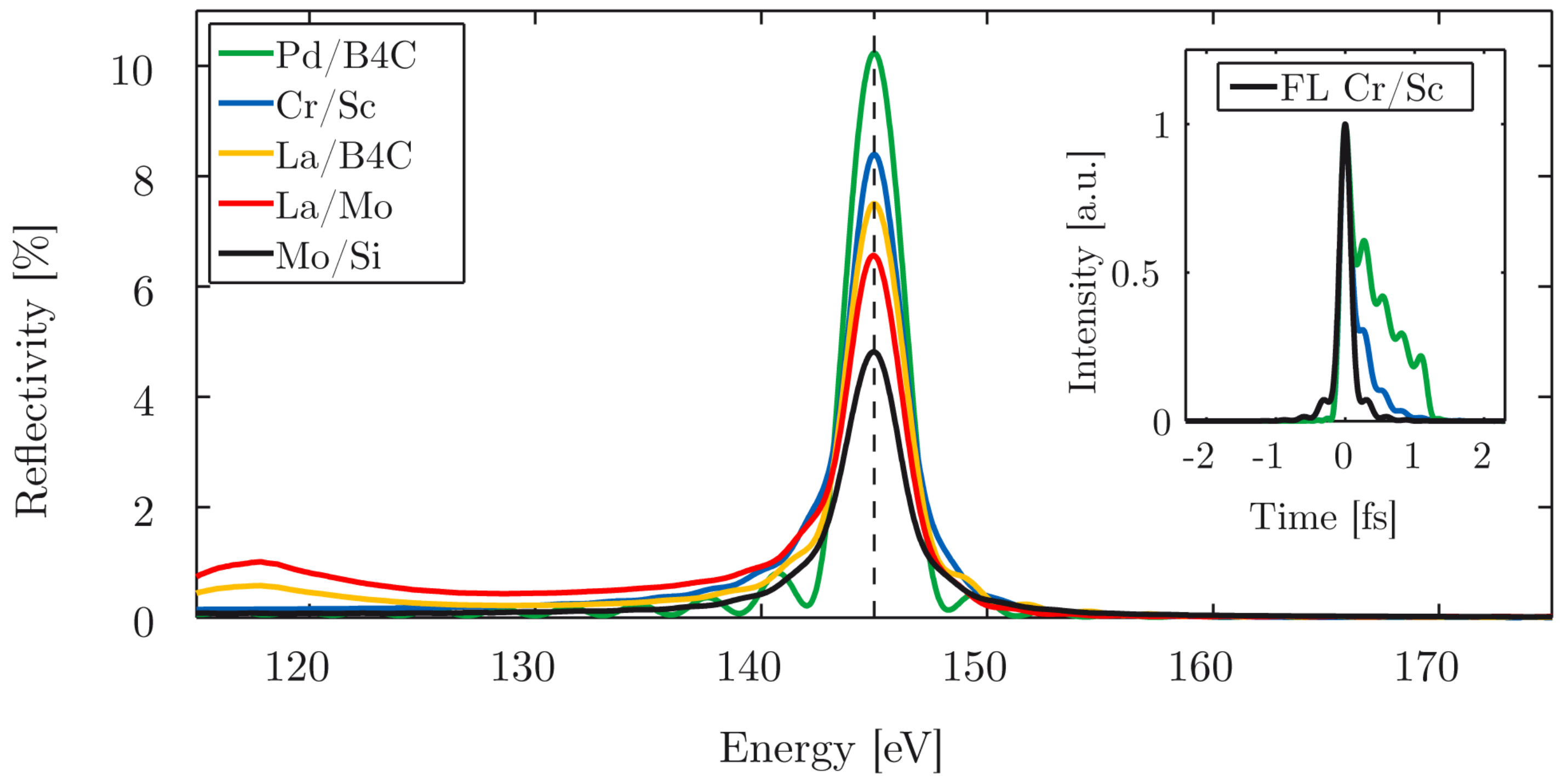
In this section, we present the first application of Cr/Sc multilayer mirrors to attosecond science. This material combination was optimized for attosecond pulses and is now applied to attosecond pulses for the first time. Most of the results were published in [66]. Previous sections demonstrated that multilayer mirrors provide a unique approach to spatial and spectral shaping, beam steering, and control of the spectral phase, with reasonably low reflective losses. It is shown below that optimizing this material system can not only be a key to (future) attosecond experiments in the water window [67] but is also a promising option for realizing new attosecond experiments around 130–160 eV—a spectral energy range wherein attosecond sources with sufficient photon flux are already available [28], but multilayer optics are limited. Figure 6 shows a simulated comparison of various established multilayer material systems reflecting attosecond pulses at a central energy of 145 eV, including an FWHM bandwidth of approximately 3 eV. The angle of incidence is normal.
The parameters were chosen as a trade-off between temporal and spectral resolution for attosecond experiments offering a high resolution. The simulations reveal an only weak suppression of (unwanted) low-energy out-of-band radiation in the range of ≈120 eV with lanthanum (La)-based multilayer mirrors (La/Mo, La/). The typically used and necessary metal filter for blocking the near-infrared laser (typically a 200 nm thick Pd filter) cannot eliminate the out-of-band radiation due to its transmission properties. Therefore, (chirped) plateau harmonics are not sufficiently suppressed by such multilayer mirrors. This is a prerequisite for filtering single isolated attosecond pulses out of the cut-off region of the high harmonic spectrum. The suppression of low-energy (out-of-band) radiation is crucial for attosecond spectroscopy experiments for, e.g., direct observation of electron propagation [34] or delay measurements [68]. Mo/Si mirrors are well established and widely used in attosecond experiments at photon energies below the silicon -edge around ≈100 eV. This material system suffers from very low reflectivity above 100 eV. On the one hand, other molybdenum (Mo)-based multilayer systems like Mo/, Mo/Y, Mo/Be, or Mo/Sr can provide a higher suppression of out-of-band radiation (in the case of Mo/) together with a higher reflectivity (Mo/Y, Mo/Be, Mo/Sr) [69,70,71,72]. However, on the other hand, they suffer from strong spectral modulations near the main reflectivity Bragg peak due to Kiessig fringes. As a result, this introduces additional group delay dispersion, which broadens the pulse in the time domain. Furthermore, beryllium (Be) is strongly toxic, and Mo/Sr is not stable since it shows long-term degradation. This limits experimental adoption of these materials. A comparison of the reflection in the time domain is shown in the small inset of Figure 6. The multilayer mirrors are composed of Cr/Sc and the highly reflective system Pd/ [73]. The simulation takes the transmission through a 200 nm thick Pd filter (including its spectral phase) into account. The pulse reflection of the Cr/Sc mirror is close to its Fourier-limit and exhibits a Gaussian pulse shape, whereas the Pd/ system clearly shows unwanted temporal pulse broadening due to group delay dispersion. Temporal modulations resulting from the multilayer reflectivity fringes are also present. The Cr/Sc material system combines all the advantages required for attosecond pulse applications: sufficient photon throughput due to the optimized reflectivity [43], suppression of out-of-band radiation (in the case of lanthanum-based systems, a thicker filter could increase the suppression in the 120 eV range, accompanied by a lower overall throughput), and a nearly Gaussian pulse profile close to the Fourier-limit, both in the temporal and spectral domain.
The experimental realization of the Cr/Sc multilayer mirror was performed by a dual ion-beam sputtering technique [67] together with a tailored interface polishing process [43] for a higher mirror reflectivity. We also analyzed the mirror by two independent measurement techniques, EUV/soft X-ray reflectometry and hard X-ray reflectometry, to support the later characterization by attosecond electron streaking. These analyses are not shown here.
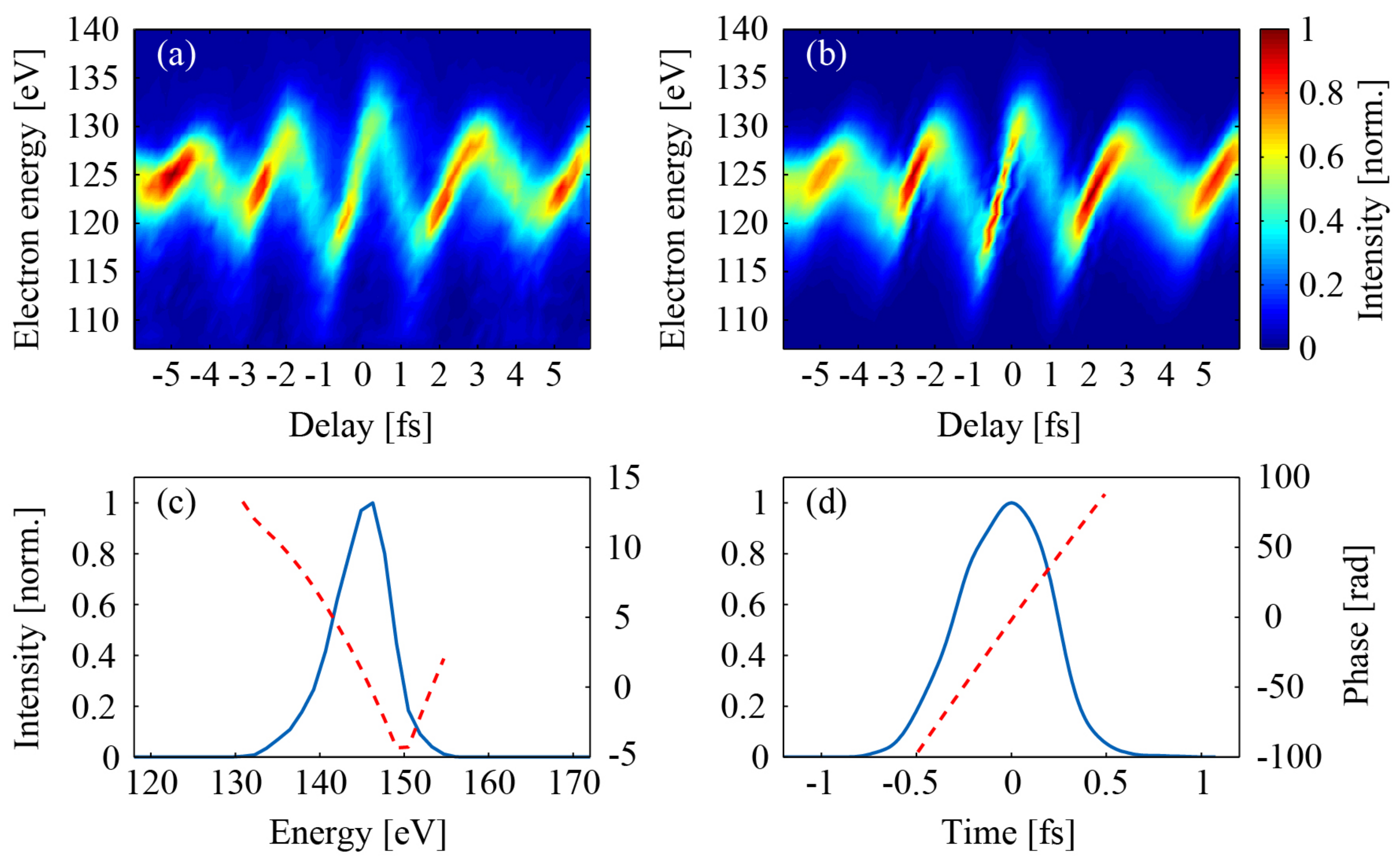
The well-established EUV-pump/NIR-probe streaking technique [61] was used to characterize the attosecond pulses upon reflection from the (Cr/Sc) multilayer mirror. Here, both an attosecond (soft X-ray) pulse and a near-infrared laser pulse are focused by a double mirror into a neon (Ne) gas jet. The soft X-ray pulse photoionizes the Ne atoms (this frees photoelectrons from the shell), which are then momentum-streaked by the co-propagating (temporally) synchronized and the phase-stabilized electric field of the NIR laser. The double mirror’s inner core can be moved with respect to the outer ring. This introduces a temporal delay between the attosecond (soft X-ray) pulse (reflected from the mirror core) and the laser pulse (reflected from the outer ring). A typical streaking spectrogram is recorded by measuring the electron energy as a function of the delay between both pulses (Figure 7a).
FROG/CRAB [63] analysis enables a complete reconstruction of both the intensity and the phase of the attosecond (soft X-ray) pulse, as well as the retrieval of the vector potential of the streaking laser field from a recorded spectrogram (Figure 7a). The result of the corresponding FROG/CRAB retrieval is shown in Figure 7b. Its theory is described in [65,74]. The retrieved intensity and phase of the attosecond (soft X-ray) pulse are depicted in Figure 7, once in the spectral (c) and once in the temporal (d) domain. To get the photon energy, the electron energy is shifted by the binding energy of the Ne- electrons ( eV). The attosecond (soft X-ray) pulse shows a central energy of 145.6 eV, which is in good agreement with the target design and the previously described results. With the retrieved spectral bandwidth and phase being the most prominent sources of uncertainty, the temporal retrieval error can be approximated to about 20 as. The retrieved amplitude and phase give a pulse duration of about 580 as in the temporal domain. This is also in excellent agreement with the previous estimations (which was based solely on the reflectivity of the mirror and the assumption of a flat mirror phase). To compare this retrieved value with the duration limit, consider that a perfect Fourier-limited Gaussian pulse with a bandwidth of 2.9 eV (FWHM) has a duration of 629 as. To summarize this work, a Cr/Sc multilayer mirror was developed and optimized for reflecting isolated attosecond pulses at a central energy of 145 eV. The successful application was proven by attosecond electron streaking, which revealed a pulse duration of 580 as.
4.4. Multilayer Mirrors for Attosecond Pulses in the Water Window Soft X-Ray Range
Time-resolved attosecond experiments are nowadays well established in the sub-120 eV EUV photon energy range [51,68,75]. With ever-improving few-cycle laser development toward higher pulse energies, this regime will be extended into the soft X-ray water window spectral range. Using thin filters for attosecond pulse shaping in this energy regime is limited to fixed opening and absorption edges of the used materials and thus restricts the degree of freedom. This leaves multilayer mirrors as the only key components for tailored spectral filtering and shaping of an attosecond water window pulse. For that reason, a negatively chirped aperiodic Cr/Sc multilayer mirror, optimized for reflecting sub-70 as pulses from HHG at a central photon energy of 326.3 eV (Ar -edge) with a bandwidth of about 30 eV (FWHM), was developed for future resonant attosecond photoionization experiments. A positively chirped mirror was realized for comparison reasons [67].
The two different aperiodic Cr/Sc multilayer mirrors were optimized by the thin film program Optilayer (version 8.85), which is described in Section 2. While the first multilayer mirror was designed for the introduction of an averaged negative chirp of approximately to compensate for a possible positive chirp of the high harmonic plateau, a second mirror with similar parameters was designed to introduce an averaged positive chirp of approximately . Both mirrors were designed such that their central energy coincides with the -edge of Ar (326.3 eV) at an incidence angle of . The optimized stack designs are shown in Figure 8, where the negative (a) and the positive (b) designs consist of around 95 individual layers.
The designs were chosen according to their robustness of GDD against small layer thickness errors. Typical layer thicknesses are between 1 and 2 nm, with the thinnest layers as small as 0.5 nm. For both designs, a top oxide layer of 1.4 nm out of 0.3 nm Cr was included in the model. These designs principally prove the large degree of freedom in customizing water window attosecond pulses, both in space (substrate shape and incidence angle) and time, utilizing aperiodic Cr/Sc multilayer mirrors.
Soft X-ray reflectometry measurements were carried out at the beamline 6.3.2 of the ALS [41] (advanced light source) in Berkeley to retrieve the reflectivity profile in the energy range for which the mirror designs target an incidence angle of . A comparison of the measured and simulated soft X-ray reflectivity for both chirped mirrors is shown in Figure 9.
The reflectivity simulations were performed using the self-written Fresnel code from Section 2 and the start designs retrieved from the Optilayer (version 8.85) optimization procedure [44]. An average Névot–Croce roughness factor of nm was retrieved from the simulations to account for interfacial imperfections. Both the central energy and the side peaks of the measurements and the designs agree very well and indicate a nearly perfect experimental implementation of the simulated multilayer stack designs of Figure 8. Also shown is the calculated evolution of the GDD within the reflectivity bandwidth of both multilayer systems, indicating an averaged GDD of ≈. Both multilayer systems are very similar in terms of peak energy, spectral bandwidth, and peak reflectivity and only differ by the sign of their GDD. Note that the spectral multilayer phase (and thus the GDD) is not accessible by simple reflectivity measurements. Measurements of the spectral phase, using soft X-ray reflectometry, have been previously reported by detecting the standing-wave assisted total electron yield from the multilayer surface as a function of the photon energy around the Bragg peak [57,76]. While this method is very suitable for periodic multilayer systems, its accuracy is limited when applied to aperiodic systems with a weak standing wave. On the other hand, one can characterize the spectral phase with two attosecond methods—the RABBITT technique [50,77] or by attosecond photoelectron streaking spectroscopy—providing access to a full characterization of the reflected attosecond pulse both in amplitude and phase [55,59]. However, for the water window, the implementation of both attosecond techniques has not been established yet due to a lack of sufficient photon flux from HHG attosecond sources in this spectral range. Here, we analyze and estimate the influence of the layer errors on the reflectivity and the GDD via simulations. The almost perfect match between the designed and the measured reflectivity in Figure 9 proves the correct elimination of systematic deposition errors and leaves only random errors to be analyzed. Both the simulated reflectivity and the GDD of the original design of the negatively chirped multilayer were compared with slightly modified designs. The designs were chosen randomly by joggling each layer thickness within predefined limits, and the merit function (MF) of the reflectivity, as well as the corresponding averaged GDD value, was calculated to analyze the quality of reflectivity and GDD simulations:
where N is the total number of wavelength samplings with integer i representing the position of the sample, with samples being equally spaced. One hundred designs were averaged per allowed error, and both the reflectivity and the GDD deviations were calculated. Designs with an overall stack height deviation of more than 0.8% were left out due to a discrepancy with parallel profilometry investigations. From Figure 10a, it can be deduced that the average random thickness error is less than 0.5%, corresponding to an average layer thickness error of approximately 0.05 angstrom.
Figure 10b shows that the GDD mean value stays nearly constant, independent of the layer errors. The upper limit of the layer errors of 0.5% corresponds to a maximum mean GDD error of approximately as. To summarize the results, we have a standard deviation of ≈0.024% in the soft X-ray reflectivity and a mean GDD of as for the aperiodic (negatively chirped) Cr/Sc multilayer mirror.
4.5. Attosecond Photoelectron Spectroscopy Utilizing Pulse Trains
Whereas many pump-probe experiments require isolated pulses, as is particularly the case for attosecond streaking, it is also possible to do time-resolved attosecond photoelectron spectroscopy utilizing pulse trains instead of isolated pulses. In this case, the combination of the fundamental laser and its high harmonics gives rise to sidebands in the spectrum of photoelectrons emitted from a target. Photoemission delays can be extracted from the delay-dependent intensity of these sidebands via RABBITT [78]. Although less intuitive than attosecond streaking, this technique is also perfectly suited to carrying out measurements with attosecond precision [79]. Moreover, it features several advantages, such as simultaneous measurement at different discrete excitation energies (i.e., with different high harmonics) and high-energy resolution due to the well-separated sharp harmonics of bandwidths of a few hundred meV. This allows for discerning different initial (or final) states within a RABBITT-trace and referencing their photoemission delays to each other [36,80,81] or resolving the band dispersion in solids and angle-dependent effects in gas and perform attosecond-ARPES [36,82,83].
EUV multilayer mirrors for RABBITT-experiments can be more broadband than for attosecond streaking, since it is not necessary to spectrally filter the cut-off region. A large mirror bandwidth can be advantageous for measuring simultaneously at multiple excitation energies [36,84]. However, if the mirror bandwidth is larger than the energy separation between two initial states that are being compared, it will complicate the data analysis because photoelectrons from different initial states and different harmonics start to overlap [80,81].
An EUV multilayer mirror design and an EUV spectrum that have been used for RABBITT measurements on tungsten [85] are depicted in Figure 11a. The mirror reflectivity is centered around 65 eV with a peak reflectivity of 40% and a bandwidth of 5 eV (FWHM) supporting about three high harmonics at a fundamental wavelength of 1030 nm. The EUV spectrum calculated from this mirror design fits well to the measured photoelectron spectrum from a tungsten (110) single crystal (Figure 11b), which features broader peaks due to the electronic band structure and a tail of slower secondary electrons.
5. Outlook
Significant achievements have already been made in terms of the performance of multilayer mirrors for attosecond pulses, but further optimization and application are possible. The realization of the first chirped multilayer mirrors for the visible spectral energy range and their first proof of successful femtosecond pulse compression was the key to implementing the idea behind those mirrors in today’s high-power laser systems and to turn them into workhorses in laser technology. Chirped pulse amplification (CPA) would be impossible without such mirrors. The realization of chirped mirrors for attosecond pulses in the EUV and even soft X-ray energy range was possible by fully controlling atomic-layer-by-atomic-layer deposition and may also open doors to key technologies and new exciting experiments, just like the mirrors for the visible range already do today.
5.1. The Way Toward Ever-Shorter Pulses: Approaching the Atomic Unit of Time
The cornerstone of attosecond physics was the key for ever-shorter pulses, since the ultrafast femtosecond pulses were superseded after several decades by attosecond pulses. The first experiment for the generation of isolated pulses proved a temporal duration of 650 as [1], and lots of subsequent experiments have realized even shorter pulses, resulting in the nowadays shortest flashes of light below 100 as. For instance, isolated attosecond pulses with a temporal duration of 80 as [55] and 67 as [87] have been measured.
With the investigation of ever more intense laser systems (HHG cut-off energy: ∼intensity) and, in parallel, moving toward laser systems with longer wavelengths (HHG cut-off energy: ∼), an ever higher cut-off energy, up to the keV, was achieved [88] and, as a consequence, broader spectra are accessible. Therefore, shorter pulses can basically be achieved. A timescale often targeted and provided is the time it takes an electron to complete one radian of its orbit in the ground state of hydrogen [89]: as (often called the atomic unit of time), where is the binding energy of the hydrogen atom (13.6 eV). The key is the multicolor high-peak-power excitation in the HHG process [90]. So, the HHG field is aiming toward high-energy few-cycle femtosecond mid-infrared lasers as prospective driver sources for strong-field applications, offering a high photon flux in a broad energy window and the opportunity for ever shorter time resolutions, approaching the atomic unit of time. Very recently, the first accuracy below the attosecond timescale was achieved. Scientists succeeded in determining the photoemission time in helium with an accuracy of 0.85 as [91].
5.2. Multilayer Mirrors for HHG Photon Energies up to the keV Spectral Range
The previous section describes the way toward ever higher photon energies in HHG but neglects one important parameter: the high photon number needed for low-cross-section attosecond experiments. Consequently, the sources should offer a high photon number (> photons) in the soft X-ray range, and multilayer mirrors being used for beam guiding, beam shaping, or beam focusing should ensure a high photon throughput. This will ensure high attosecond pulse intensities on the target to be investigated. The way toward higher photon energies combined with a high photon flux leaves only one direction for multilayer mirrors: toward grazing incidence optics. Grazing incidence optics are the key for photon energies above the water window (>)—up to the keV range—for four distinct reasons:
- High single interface reflectivity for grazing incidence.
- For grazing optics, in the case of keV: A photon energy of 1000 eV corresponds to a wavelength of nm. This leads, in the case of normal incidence, to a period in a multilayer mirror. Assuming typical two-material systems, one ends up in a layer with a thickness of ∼ nm, which is close to the limit of technical realization.
- One can minimize the influence of the roughness on the reflectivity performance: The lower the -ratio, the lower is the reflectivity loss. One thus can minimize the reflectivity loss by reducing the interface roughness or increase the period thickness d. Keeping the central energy from a multilayer mirror constant leads, in the case of a higher period thickness, to a lower grazing incidence angle. This overlaps with the previous statement. Typical roughness values are in the range of 0.4–0.6 nm. Comparable thickness values are strongly discouraged.
- In the case of grazing incidence (compared with multilayer mirrors at normal incidence), only a few layers can contribute to the overall reflectivity, which results in a certain energy in a higher spectral bandwidth support. According to the relation between bandwidth and temporal pulse duration, , this presents the opportunity for shorter pulses.
6. Conclusions
Multilayer mirror investigations over the last decades have paved their way from applications in the visible/infrared range to those in the EUV/soft X-ray spectral range in terms of spectral characteristics while advancing from the picosecond/femtosecond down to the attosecond regime in terms of temporal considerations. These mirrors are nowadays already used by default in attosecond science in the EUV/soft X-ray range. This is attributed to the substantial improvements being realized by an optimized combination of deposition, simulation, and characterization methods. Due to their high degrees of freedom, multilayer mirrors will remain a key component in attosecond beamlines as pulse shaping elements. Further investigations will continue to carve the way toward attosecond physics at ever higher spectral ranges and with ever shorter pulses.
Author Contributions
We confirm that all authors contributed to this manuscript. A.G. and Y.C. wrote the manuscript and contributed equally to this work. S.H. did the work on the RABBITT section. U.K. did project management and gave initial ideas. All authors did the final manuscript review.
Funding
This research was funded by DFG (German Research Foundation) grant number EXC158. Alexander Guggenmos acknowledges support from the German Research Foundation (GU 1642/1-1).
Acknowledgments
We strongly acknowledge scientific support by Michael Hofstetter (MPQ, LMU) and we thankfully acknowledge scientific support and valuable discussions by Ferenc Krausz (MPQ, LMU).
Conflicts of Interest
The authors declare no conflict of interest. The founding sponsors had no role in the design of the study; in the collection, analyses, or interpretation of data; in the writing of the manuscript, and in the decision to publish the results.
References
- Hentschel, M.; Kienberger, R.; Spielmann, C.; Reider, G.A.; Milosevic, N.; Brabec, T.; Corkum, P.; Heinzmann, U.; Drescher, M.; Krausz, F. Attosecond metrology. Nature 2001, 414, 509–513. [Google Scholar] [CrossRef] [PubMed]
- Morawe, C.; Osterhoff, M. Hard X-ray focusing with curved reflective multilayers. X-Ray Opt. Instrum. 2010, 2010, 479631. [Google Scholar] [CrossRef]
- Schmidt, J.; Guggenmos, A.; Hofstetter, M.; Chew, S.H.; Kleineberg, U. Generation of circularly polarized high harmonic radiation using a transmission multilayer quarter waveplate. Opt. Express 2015, 23, 33564. [Google Scholar] [CrossRef] [PubMed]
- Zürch, M.; Rothhardt, J.; Hädrich, S.; Demmler, S.; Krebs, M.; Limpert, J.; Tünnermann, A.; Guggenmos, A.; Kleineberg, U.; Spielmann, C. Real-time and sub-wavelength ultrafast coherent diffraction imaging in the extreme ultraviolet. Sci. Rep. 2014, 4, 1–5. [Google Scholar] [CrossRef]
- Spiller, E. Reflective multilayer coatings for the far UV region. Appl. Opt. 1976, 15, 2333–2338. [Google Scholar] [CrossRef]
- Bajt, S. Improved reflectance and stability of Mo-Si multilayers. Opt. Eng. 2002, 41, 1797. [Google Scholar] [CrossRef]
- Kozhevnikov, I.V.; Balakireva, L.L.; Fedorenko, A.I.; Kopealets, I.A.; Levashov, V.E.; Stetsenko, A.N.; Struk, I.I.; Vinogradov, A.V. Synthesis and measurement of Os-Si multilayer mirrors optimized for the wavelength 380 Å. Opt. Commun. 1996, 125, 13–17. [Google Scholar] [CrossRef]
- Rajesh, S.; Arivazhagan, V.; Parvathi, M.M. Structural, optical and electrical properties of vacuum evaporated PbSe/ZnSe multilayer thin films. AIP Conf. Proc. 2012, 1451, 197–199. [Google Scholar] [CrossRef]
- Skulina, K.M.; Alford, C.S.; Bionta, R.M.; Makowiecki, D.M.; Gullikson, E.M.; Soufli, R.; Kortright, J.B.; Underwood, J.H. Molybdenum/beryllium multilayer mirrors for normal incidence in the extreme ultraviolet. Appl. Opt. 1995, 34, 3727. [Google Scholar] [CrossRef]
- Bajt, S.; Stearns, D.G.; Kearney, P.A. Investigation of the amorphous-to-crystalline transition in Mo/Si multilayers. J. Appl. Phys. 2001, 90, 1017–1025. [Google Scholar] [CrossRef]
- Rao, P.N.; Nayak, M.; Lodha, G.S.; Rai, S.K.; Srivastava, A.K.; Modi, M.H.; Sagdeo, A. Fabrication and evaluation of large area Mo/Si soft X-ray multilayer mirrors at Indus SR facilities. Adv. Opt. Technol. 2012, 2012, 976868. [Google Scholar] [CrossRef]
- Voronov, D.L.; Gawlitza, P.; Cambie, R.; Dhuey, S.; Gullikson, E.M.; Warwick, T.; Braun, S.; Yashchuk, V.V.; Padmore, H.A. Conformal growth of Mo/Si multilayers on grating substrates using collimated ion beam sputtering. J. Appl. Phys. 2012, 111, 093521. [Google Scholar] [CrossRef] [Green Version]
- El Hajj, A.; Lucas, B.; Chakaroun, M.; Antony, R.; Ratier, B.; Aldissi, M. Optimization of ZnO/Ag/ZnO multilayer electrodes obtained by Ion Beam Sputtering for optoelectronic devices. Thin Solid Films 2012, 520, 4666–4668. [Google Scholar] [CrossRef]
- Grigonis, M.; Émile, J. Knystautas. C/Si multilayer mirrors for the 25–30-nm wavelength region. Appl. Opt. 1997, 36, 2839–2842. [Google Scholar] [CrossRef] [PubMed]
- Wang, Z.; Zhao, H.; Yao, Q.; Xu, J.; Kimura, H. Structure and magnetism of ZnO/Co multilayers prepared by pulsed laser deposition. Cryst. Res. Technol. 2012, 47, 799–803. [Google Scholar] [CrossRef]
- Siraj, K.; Khaleeq-Ur-Rahman, M.; Rafique, M.S.; Munawar, M.Z.; Naseem, S.; Riaz, S. Pulsed laser deposition and characterization of multilayer metal-carbon thin films. Appl. Surf. Sci. 2011, 257, 6445–6450. [Google Scholar] [CrossRef]
- Chrisey, D.B.; Hubler, G.K. Pulsed Laser Deposition of Thin Films; John Wiley & Sons, Inc.: New York, NY, USA, 1994. [Google Scholar]
- Martínez-Galarce, D.; Soufli, R.; Windt, D.L.; Bruner, M.; Gullikson, E.; Khatri, S.; Spiller, E.; Robinson, J.C.; Baker, S.; Prast, E. Multisegmented, multilayer-coated mirrors for the Solar Ultraviolet Imager. Opt. Eng. 2013, 52, 095102. [Google Scholar] [CrossRef] [Green Version]
- Wagner, C.; Harned, N. EUV lithography: Lithography gets extreme. Nat. Photonics 2010, 4, 24–26. [Google Scholar] [CrossRef]
- Chao, W.; Kim, J.; Rekawa, S.; Fischer, P.; Anderson, E.H. Demonstration of 12 nm Resolution Fresnel Zone Plate Lens based Soft X-ray Microscopy. Opt. Express 2009, 17, 17669. [Google Scholar] [CrossRef]
- Champeaux, J.P.; Troussel, P.; Villier, B.; Vidal, V.; Khachroum, T.; Vidal, B.; Krumrey, M. Development and realization of non-periodic W/Si multilayer mirrors for 5–14 keV X-ray plasma diagnostic. Nucl. Instrum. Methods Phys. Res. Sec. A 2007, 581, 687–694. [Google Scholar] [CrossRef]
- Andronova, N.V.; Kohn, V.G.; Chechin, A.I. Multilayer mirrors as synchrotron radiation monochromators. Nucl. Inst. Methods Phys. Res. A 1995, 359, 131–134. [Google Scholar] [CrossRef]
- Ferray, M.; L’Huillier, A.; Li, X.F.; Lomprk, L.A.; Mainfray, G.; Manus, C. Multiple-harmonic conversion of 1064 nm radiationin rare gases. J. Phys. B Atomic Mol. Opt. Phys. 1988, 21, L31. [Google Scholar] [CrossRef]
- Prasciolu, M.; Leontowich, A.F.G.; Beyerlein, K.R.; Bajt, S. Thermal stability studies of short period Sc/Cr and Sc/B4C/Cr multilayers. Appl. Opt. 2014, 53, 2126. [Google Scholar] [CrossRef] [PubMed]
- Helml, W.; Maier, A.R.; Schweinberger, W.; Grguraš, I.; Radcliffe, P.; Doumy, G.; Roedig, C.; Gagnon, J.; Messerschmidt, M.; Schorb, S.; et al. Measuring the temporal structure of few-femtosecond free-electron laser X-ray pulses directly in the time domain. Nat. Photonics 2014, 8, 950–957. [Google Scholar] [CrossRef]
- Kling, M.F.; Vrakking, M.J. Attosecond Electron Dynamics. Annu. Rev. Phys. Chem. 2008, 59, 463–492. [Google Scholar] [CrossRef] [PubMed]
- Fie, M.; Schultze, M.; Goulielmakis, E.; Dennhardt, B.; Gagnon, J.; Hofstetter, M.; Kienberger, R.; Krausz, F. Versatile apparatus for attosecond metrology and spectroscopy. Rev. Sci. Instrum. 2010, 81, 093103. [Google Scholar] [CrossRef]
- Schweinberger, W.; Sommer, A.; Bothschafter, E.; Li, J.; Krausz, F.; Kienberger, R.; Schultze, M. Waveform-controlled near-single-cycle milli-joule laser pulses generate sub-10 nm extreme ultraviolet continua. Opt. Lett. 2012, 37, 3573. [Google Scholar] [CrossRef]
- Corkum, P.B. Plasma perspective on strong field multiphoton ionization. Phys. Rev. Lett. 1993, 71, 1994–1997. [Google Scholar] [CrossRef] [Green Version]
- Descamps, D.; Lyngå, C.; Norin, J.; L’huillier, A.; Wahlström, C.G.; Hergott, J.F.; Merdji, H.; Salières, P.; Bellini, M.; Hänsch, T.W. Extreme ultraviolet interferometry measurements with high-order harmonics. Opt. Lett. 2000, 25, 135–137. [Google Scholar] [CrossRef] [Green Version]
- Lee, J.; Carlson, D.R.; Jones, R.J. Optimizing intracavity high harmonic generation for XUV fs frequency combs. Opt. Express 2011, 19, 23315–23326. [Google Scholar] [CrossRef]
- Goulielmakis, E.; Loh, Z.H.; Wirth, A.; Santra, R.; Rohringer, N.; Yakovlev, V.S.; Zherebtsov, S.; Pfeifer, T.; Azzeer, A.M.; Kling, M.F.; et al. Real-time observation of valence electron motion. Nature 2010, 466, 739–743. [Google Scholar] [CrossRef] [PubMed]
- Nisoli, M.; Decleva, P.; Calegari, F.; Palacios, A.; Martín, F. Attosecond Electron Dynamics in Molecules. Chem. Rev. 2017, 117, 10760–10825. [Google Scholar] [CrossRef] [PubMed]
- Neppl, S.; Ernstorfer, R.; Cavalieri, A.L.; Lemell, C.; Wachter, G.; Magerl, E.; Bothschafter, E.M.; Jobst, M.; Hofstetter, M.; Kleineberg, U.; et al. Direct observation of electron propagation and dielectric screening on the atomic length scale. Nature 2015, 517, 342–346. [Google Scholar] [CrossRef] [PubMed] [Green Version]
- Chew, S.H.; Sümann, F.; Späth, C.; Wirth, A.; Schmidt, J.; Zherebtsov, S.; Guggenmos, A.; Oelsner, A.; Weber, N.; Kapaldo, J.; et al. Time-of-flight-photoelectron emission microscopy on plasmonic structures using attosecond extreme ultraviolet pulses. Appl. Phys. Lett. 2012, 100, 1–5. [Google Scholar] [CrossRef]
- Tao, Z.; Chen, C.; Szilvási, T.; Keller, M.; Mavrikakis, M.; Kapteyn, H.; Murnane, M. Direct time-domain observation of attosecond final-state lifetimes in photoemission from solids. Science 2016, 353, 62–67. [Google Scholar] [CrossRef] [PubMed]
- Henke, B.L.; Gullikson, E.M.; Davis, J.C. X-ray interactions: photoabsorption, scattering, transmission, and reflection at E = 50-30000 eV, Z = 1-92. Atomic Data Nucl. Data Tables 1993, 54, 181–342. [Google Scholar] [CrossRef]
- Chi, E.; Shim, J.; Kwak, J.; Baik, H. Silicide formation by solid-state diffusion in Mo/Si multilayer thin films. J. Mater. Sci. 1996, 31, 3567–3572. [Google Scholar] [CrossRef]
- Hofstetter, M.; Aquila, A.; Schultze, M.; Guggenmos, A.; Yang, S.; Gullikson, E.; Huth, M.; Nickel, B.; Gagnon, J.; Yakovlev, V.S.; et al. Lanthanum-molybdenum multilayer mirrors for attosecond pulses between 80 and 130 eV. New J. Phys. 2011, 13, 063038. [Google Scholar] [CrossRef]
- Gerald, E.; Jellison, J. Data Analysis for Spectroscopic Ellipsometry. In Handbook of Ellipsometry; Tompkins, H.G., Irene, E.A., Eds.; William Andrew Publishing: Norwich, NY, USA, 2005; pp. 237–296. [Google Scholar]
- Gullikson, E.M.; Mrowka, S.; Kaufmann, B.B. Recent Developments in EUV Reflectometry at the Advanced Light Source. Proc. SPIE 2001, 4343, 363–373. [Google Scholar] [CrossRef]
- Singh, S.; Basu, S.; Bhatt, P.; Poswal, A.K. Kinetics of alloy formation at the interfaces in a Ni-Ti multilayer: X-ray and neutron reflectometry study. Phys. Rev. B 2009, 79, 1–9. [Google Scholar] [CrossRef]
- Guggenmos, A.; Radünz, S.; Rauhut, R.; Hofstetter, M.; Venkatesan, S.; Wochnik, A.; Gullikson, E.M.; Fischer, S.; Nickel, B.; Scheu, C.; et al. Ion polished Cr/Sc attosecond multilayer mirrors for high water window reflectivity. Opt. Express 2014, 22, 26526–26536. [Google Scholar] [CrossRef]
- Tikhonravov, A.V.; Trubetskov, M.K.; DeBell, G.W. Optical coating design approaches based on the needle optimization technique. Appl. Opt. 2007, 46, 704–710. [Google Scholar] [CrossRef] [PubMed]
- Yakovlev, V.; Tempea, G. Optimization of chirped mirrors. Appl. Opt. 2002, 41, 6514–6520. [Google Scholar] [CrossRef] [PubMed]
- Hamelmann, F.; Haindl, G.; Schmalhorst, J.; Aschentrup, A.; Majkova, E.; Kleineberg, U.; Heinzmann, U.; Klipp, A.; Jutzi, P.; Anopchenko, A.; et al. Metal oxide/silicon oxide multilayer with smooth interfaces produced by in situ controlled plasma-enhanced MOCVD. Thin Solid Films 2000, 358, 90–93. [Google Scholar] [CrossRef]
- Thornton, R.L.; Burnham, R.D.; Streifer, W. High reflectivity GaAs-AlGaAs mirrors fabricated by metalorganic chemical vapor deposition. Appl. Phys. Lett. 1984, 45, 1028–1030. [Google Scholar] [CrossRef]
- Corkum, P.; Krausz, F. Attosecond science. Nat. Phys. 2007, 3, 381–387. [Google Scholar] [CrossRef]
- Krausz, F.; Ivanov, M. Attosecond physics. Rev. Mod. Phys. 2009, 81, 163–234. [Google Scholar] [CrossRef]
- López-Martens, R.; Varjú, K.; Johnsson, P.; Mauritsson, J.; Mairesse, Y.; Salières, P.; Gaarde, M.B.; Schafer, K.J.; Persson, A.; Svanberg, S.; et al. Amplitude and phase control of attosecond light pulses. Phys. Rev. Lett. 2005, 94, 1–4. [Google Scholar] [CrossRef]
- Sansone, G.; Benedetti, E.; Calegari, F.; Vozzi, C.; Avaldi, L.; Flammini, R.; Poletto, L.; Villoresi, P.; Altucci, C.; Velotta, R.; et al. Isolated Single-Cycle Attosecond Pulses. Science 2006, 314, 443–446. [Google Scholar] [CrossRef]
- Rohwer, T.; Hellmann, S.; Wiesenmayer, M.; Sohrt, C.; Stange, A.; Slomski, B.; Carr, A.; Liu, Y.; Avila, L.M.; Kalläsignne, M.; et al. Collapse of long-range charge order tracked by time-resolved photoemission at high momenta. Nature 2011, 471, 490–494. [Google Scholar] [CrossRef]
- Morlens, A.S.; López-Martens, R.; Boyko, O.; Zeitoun, P.; Balcou, P.; Varjú, K.; Gustafsson, E.; Remetter, T.; L’Huillier, A.; Kazamias, S.; et al. Design and characterization of extreme-ultraviolet broadband mirrors for attosecond science. Opt. Lett. 2006, 31, 1558. [Google Scholar] [CrossRef] [PubMed] [Green Version]
- Uspenskii, Y.A.; Levashov, V.E.; Vinogradov, A.V.; Fedorenko, A.I.; Kondratenko, V.V.; Pershin, Y.P.; Zubarev, E.N.; Mrowka, S.; Schäfers, F. Sc-Si normal incidence mirrors for a VUV interval of 35–50 nm. Nucl. Instrum. Methods Phys. Res. Sec. A 2000, 448, 147–151. [Google Scholar] [CrossRef]
- Goulielmakis, E.; Schultze, M.; Hofstetter, M.; Yakovlev, V.S.; Gagnon, J.; Uiberacker, M.; Aquila, A.L.; Gullikson, E.M.; Attwood, D.T.; Kienberger, R.; et al. Single-Cycle Nonlinear Optics. Science 2008, 320, 1614–1617. [Google Scholar] [CrossRef] [PubMed] [Green Version]
- Guggenmos, A.; Akil, A.; Ossiander, M.; Schäffer, M.; Azzeer, A.M.; Boehm, G.; Amann, M.C.; Kienberger, R.; Schultze, M.; Kleineberg, U. Attosecond photoelectron streaking with enhanced energy resolution for small-bandgap materials. Opt. Lett. 2016, 41, 3714. [Google Scholar] [CrossRef] [PubMed]
- Bourassin-Bouchet, C.; De Rossi, S.; Wang, J.; Meltchakov, E.; Giglia, A.; Mahne, N.; Nannarone, S.; Delmotte, F. Shaping of single-cycle sub-50-attosecond pulses with multilayer mirrors. New J. Phys. 2012, 14, 023040. [Google Scholar] [CrossRef] [Green Version]
- Hofstetter, M.; Schultze, M.; Fieß, M.; Dennhardt, B.; Guggenmos, A.; Gagnon, J.; Yakovlev, V.S.; Goulielmakis, E.; Kienberger, R.; Gullikson, E.M.; et al. Attosecond dispersion control by extreme ultraviolet multilayer mirrors. Opt. Express 2011, 19, 1767. [Google Scholar] [CrossRef] [PubMed]
- Ménesguen, Y.; De Rossi, S.; Meltchakov, E.; Delmotte, F. Aperiodic multilayer mirrors for efficient broadband reflection in the extreme ultraviolet. Appl. Phys. A Mater. Sci. Process. 2010, 98, 305–309. [Google Scholar] [CrossRef]
- Gullikson, E.; Underwood, J.; Batson, P.; Nikitin, V. A soft x-ray/EUV reflectometer based on a laser produced plasma source. J. X-Ray Sci. Technol. 1992, 3, 283–299. [Google Scholar] [CrossRef]
- Kienberger, R.; Goulielmakis, E.; Uiberacker, M.; Baltuska, A.; Yakovlev, V.; Bammer, F.; Scrinzi, A.; Westerwalbesloh, T.; Kleineberg, U.; Heinzmann, U.; et al. Atomic transient recorder. Nature 2004, 427, 817–821. [Google Scholar] [CrossRef]
- Kitzler, M.; Milosevic, N.; Scrinzi, A.; Krausz, F.; Brabec, T. Quantum Theory of Attosecond XUV Pulse Measurement by Laser Dressed Photoionization. Phys. Rev. Lett. 2002, 88, 4. [Google Scholar] [CrossRef]
- Trebino, R.; DeLong, K.W.; Fittinghoff, D.N.; Sweetser, J.N.; Krumbügel, M.A.; Richman, B.A.; Kane, D.J. Measuring ultrashort laser pulses in the time-frequency domain using frequency-resolved optical gating. Rev. Sci. Instrum. 1997, 68, 3277–3295. [Google Scholar] [CrossRef]
- Mairesse, Y.; de Bohan, A.; Frasinski, L.J.; Merdji, H.; Dinu, L.C.; Monchicourt, P.; Breger, P.; Kovačev, M.; Taïeb, R.; Carré, B.; et al. Attosecond Synchronization of High-Harmonic Soft X-rays. Science 2003, 302, 1540–1543. [Google Scholar] [CrossRef]
- Gagnon, J.; Goulielmakis, E.; Yakovlev, V.S. The accurate FROG characterization of attosecond pulses from streaking measurements. Appl. Phys. B Lasers Opt. 2008, 92, 25–32. [Google Scholar] [CrossRef] [Green Version]
- Guggenmos, A.; Jobst, M.; Ossiander, M.; Radünz, S.; Riemensberger, J.; Schäffer, M.; Akil, A.; Jakubeit, C.; Böhm, P.; Noever, S.; et al. Chromium/scandium multilayer mirrors for isolated attosecond pulses at 145 eV. Opt. Lett. 2015, 40, 2846–2849. [Google Scholar] [CrossRef] [PubMed]
- Guggenmos, A.; Rauhut, R.; Hofstetter, M.; Hertrich, S.; Nickel, B.; Schmidt, J.; Gullikson, E.M.; Seibald, M.; Schnick, W.; Kleineberg, U. Aperiodic CrSc multilayer mirrors for attosecond water window pulses. Opt. Express 2013, 21, 21728–21740. [Google Scholar] [CrossRef] [PubMed]
- Schultze, M.; Fieß, M.; Karpowicz, N.; Gagnon, J.; Korbman, M.; Hofstetter, M.; Neppl, S.; Cavalieri, A.L.; Komninos, Y.; Mercouris, T.; et al. Delay in Photoemission. Science 2010, 1658, 1658–1662. [Google Scholar] [CrossRef]
- Montcalm, C.; Sullivan, B.T.; Duguay, S.; Ranger, M.; Steffens, W.; Pépin, H.; Chaker, M. In situ reflectance measurements of soft-x-ray/extreme-ultraviolet Mo/Y multilayer mirrors. Opt. Lett. 1995, 20, 1450–1452. [Google Scholar] [CrossRef]
- Soufli, R.; Spiller, E.; Windt, D.L.; Robinson, J.C.; Gullikson, E.M.; Rodriguez-de Marcos, L.; Fernández-Perea, M.; Baker, S.L.; Aquila, A.L.; Dollar, F.J.; et al. In-band and out-of-band reflectance calibrations of the EUV multilayer mirrors of the Atmospheric Imaging Assembly Instrument aboard the Solar Dynamics Observatory. Proc. SPIE 2012, 8443, 84433C. [Google Scholar] [CrossRef]
- Bajt, S. Molybdenum–ruthenium/beryllium multilayer coatings. J. Vac. Sci. Technol. A 2000, 18, 557–559. [Google Scholar] [CrossRef]
- Sae-Lao, B.; Montcalm, C. Molybdenum-strontium multilayer mirrors for the 8–12 nm extreme-ultraviolet wavelength region. Opt. Lett. 2001, 26, 468–470. [Google Scholar] [CrossRef]
- Montcalm, C.; Kearney, P.A.; Slaughter, J.M.; Sullivan, B.T.; Chaker, M.; Pépin, H.; Falco, C.M. Survey of Ti-, B-, and Y-based soft x-ray-extreme ultraviolet multilayer mirrors for the 2- to 12-nm wavelength region. Appl. Opt. 1996, 35, 5134–5147. [Google Scholar] [CrossRef] [PubMed]
- Gagnon, J.; Yakovlev, V.S. The robustness of attosecond streaking measurements. Opt. Express 2009, 17, 17678. [Google Scholar] [CrossRef] [PubMed]
- Neppl, S.; Ernstorfer, R.; Bothschafter, E.M.; Cavalieri, A.L.; Menzel, D.; Barth, J.V.; Krausz, F.; Kienberger, R.; Feulner, P. Attosecond time-resolved photoemission from core and valence states of magnesium. Phys. Rev. Lett. 2012, 109, 22–26. [Google Scholar] [CrossRef] [PubMed]
- Aquila, A.; Salmassi, F.; Gullikson, E. Metrologies for the phase characterization of attosecond extreme ultraviolet optics. Opt. Lett. 2008, 33, 455–457. [Google Scholar] [CrossRef]
- Muller, H.G. Reconstruction of attosecond harmonic beating by interference of two-photon transitions. Appl. Phys. B Lasers Opt. 2002, 74, 17–21. [Google Scholar] [CrossRef]
- Paul, P.M.; Toma, E.S.; Breger, P.; Mullot, G.; Augé, F.; Balcou, P.; Muller, H.G.; Agostini, P. Observation of a Train of Attosecond Pulses from High Harmonic Generation. Science 2001, 292, 1689–1692. [Google Scholar] [CrossRef] [PubMed]
- Cattaneo, L.; Vos, J.; Lucchini, M.; Gallmann, L.; Cirelli, C.; Keller, U. Comparison of attosecond streaking and RABBITT. Opt. Express 2016, 24, 29060–29076. [Google Scholar] [CrossRef] [PubMed]
- Isinger, M.; Squibb, R.; Busto, D.; Zhong, S.; Harth, A.; Kroon, D.; Nandi, S.; Arnold, C.L.; Miranda, M.; Dahlström, J.M.; et al. Photoionization in the time and frequency domain. Science 2017, 358, 893–896. [Google Scholar] [CrossRef] [Green Version]
- Jain, A.; Gaumnitz, T.; Bray, A.; Kheifets, A.; Wörner, H.J. Photoionization delays in xenon using single-shot referencing in the collinear back-focusing geometry. Opt. Lett. 2018, 43, 4510–4513. [Google Scholar] [CrossRef]
- Heuser, S.; Jiménez Galán, A.; Cirelli, C.; Marante, C.; Sabbar, M.; Boge, R.; Lucchini, M.; Gallmann, L.; Ivanov, I.; Kheifets, A.S.; et al. Angular dependence of photoemission time delay in helium. Phys. Rev. A 2016, 94, 063409. [Google Scholar] [CrossRef]
- Lucchini, M.; Castiglioni, L.; Kasmi, L.; Kliuiev, P.; Ludwig, A.; Greif, M.; Osterwalder, J.; Hengsberger, M.; Gallmann, L.; Keller, U. Light-Matter Interaction at Surfaces in the Spatiotemporal Limit of Macroscopic Models. Phys. Rev. Lett. 2015, 115, 137401. [Google Scholar] [CrossRef] [PubMed] [Green Version]
- Locher, R.; Castiglioni, L.; Lucchini, M.; Greif, M.; Gallmann, L.; Osterwalder, J.; Hengsberger, M.; Keller, U. Energy-dependent photoemission delays from noble metal surfaces by attosecond interferometry. Optica 2015, 2, 405–410. [Google Scholar] [CrossRef]
- Heinrich, S.; Saule, T.; Högner, M.; Cui, Y.; Guggenmos, A.; Pupeza, I.; Kleineberg, U. Energy dependent attosecond photoemission delays from core and valence band states of tungsten. 2018; in press. [Google Scholar]
- Strayer, R.; Mackie, W.; Swanson, L. Work function measurements by the field emission retarding potential method. Surf. Sci. 1973, 34, 225–248. [Google Scholar] [CrossRef] [Green Version]
- Zhao, K.; Zhang, Q.; Chini, M.; Wu, Y.; Wang, X.; Chang, Z. Tailoring a 67 attosecond pulse through advantageous phase-mismatch. Opt. Lett. 2012, 37, 3891. [Google Scholar] [CrossRef] [PubMed]
- Popmintchev, T.; Chen, M.C.; Popmintchev, D.; Arpin, P.; Brown, S.; Ališauskas, S.; Andriukaitis, G.; Balčiunas, T.; Mücke, O.D.; Pugzlys, A.; et al. Bright coherent ultrahigh harmonics in the kev x-ray regime from mid-infrared femtosecond lasers. Science 2012, 336, 1287–1291. [Google Scholar] [CrossRef] [PubMed]
- Bucksbaum, P.H. The future of attosecond spectroscopy. Science 2007, 317, 766–769. [Google Scholar] [CrossRef] [PubMed]
- Haessler, S.; Balčiunas, T.; Fan, G.; Chipperfield, L.E.; Baltuška, A. Enhanced multi-colour gating for the generation of high-power isolated attosecond pulses. Sci. Rep. 2015, 5, 1–15. [Google Scholar] [CrossRef] [Green Version]
- Ossiander, M.; Siegrist, F.; Shirvanyan, V.; Pazourek, R.; Sommer, A.; Latka, T.; Guggenmos, A.; Nagele, S.; Feist, J.; Burgdörfer, J.; et al. Attosecond correlation dynamics. Nat. Phys. 2017, 13, 280–285. [Google Scholar] [CrossRef]
Figure 1.
Broadband normal incidence extreme ultraviolet (EUV) multilayer mirror between 30 and 55 eV. Panel (a) shows simulated (black) and measured (green) EUV reflectivity and spectral phase (red dash-dotted line). An interface roughness of nm was used in the simulation. Panel (b) shows the appropriate design of the 10 periods, period thickness of nm, Si/Sc stack. Panel (c) is the temporal structure of the mirror calculated as the Fourier transform of its spectral shape. It supports the reflection of 165 as sub-2 cycle EUV pulses.

Figure 2.
Panel (a) shows the simulated (black line) and measured (green crosses) reflectivity of a 32 eV (full-width-at-half-maximum, FWHM) bandwidth flat phase (red dash-dotted line) multilayer mirror (design plotted in panel (b)), revealing a measured 3.6% reflectivity centered at 70 eV. Together with a 300 nm thick Zr filter (yellow dotted line), it functions as a 25 eV (FWHM) broad bandpass and compressor (blue dashed line) for the generation of 80 as EUV pulses. Panel (c) shows the simulated 64 as long pulse (black line) and the temporal phase (red circles) of a pulse supported by the mirror upon reflection as an outcome of Fourier transformation of the mirror’s spectrum. The blue dashed line shows the temporal structure of the bandpass (mirror + filter), resulting in a 90 as long pulse, compared with its Fourier-limit (light green dash-dotted line) of 80 as.

Figure 3.
Characteristics of EUV chirped multilayer coatings designed and manufactured for the experiments. A set of EUV multilayers with positive (a), near-zero (b), and negative (c) group delay dispersion (GDD). The diagrams compare the measured (solid black) with the designed (dotted green) reflectivity curves. The calculated group delays (derivative of the spectral phase with respect to angular frequency) are also displayed (dashed red curve). The transmission of a 150 nm thick palladium (Pd) foil is additionally qualitatively plotted in panel (b), depicted by the blue dash-dotted line. The lower panels (d–f) show the corresponding mirror designs of the appropriate mirrors above. Each color represents one material, as explained in the legend of (e).

Figure 4.
Measured and retrieved attosecond electron streaking spectrograms in the upper and lower row, respectively. Panels (a–f) display spectrograms recorded with attosecond pulses reflected off the mirrors described in Figure 3a–c, respectively. The energy shift in the recorded spectra is proportional to the vector potential of the streaking laser field at the instant of photoemission; hence, the dependence of this energy shift on the delay between the attosecond EUV pulse and the NIR laser field reflects the temporal evolution of the NIR laser field’s vector potential, . Narrowing and broadening in the streaked electron spectra at the zero crossings are displayed by enhanced and diminished electron count rates, respectively. The small insets show the energy-calibrated raw data before subtraction of the background.

Figure 5.
Retrieved spectral and temporal characteristics of the attosecond EUV pulse in the upper row and lower row, respectively. Panels (a–c) display the intensity spectrum (green dotted line) and group delay (red dashed line) of the attosecond (EUV) pulse reflected off the mirrors described in Figure 3a–c, respectively. The retrieval from the measured streaking spectrograms are shown in Figure 4a–c, respectively. The black full lines depict the corresponding EUV spectra measured directly with an EUV spectrometer. The evaluated effective group delay dispersion values weighted by the final spectral EUV intensity are also shown. Panels (d–f) show the temporal intensity profile (black line) and temporal phase (red dashed line) retrieved from the streaking spectrograms of Figure 4a–c, respectively. The EUV pulse duration (FWHM) was evaluated and is displayed at the bottom of each panel.

Figure 6.
The reflectivity performance of various material systems is compared around 145 eV. The simulated comparison is for a reflection of an FWHM bandwidth of 3 eV centered at a photon energy of 145 eV. A comparison in the time domain is shown in the small inset for the Cr/Sc and Pd/ system, including already the transmission through a 200 nm thick Pd filter. The Fourier-limit of the Cr/Sc mirror is shown in black.

Figure 7.
Measured attosecond electron streaking at a photon energy of 145 eV and the corresponding retrievals. This technique was used for attosecond pulse characterization in a neon gas jet utilizing the Cr/Sc multilayer mirror. (a) Measured electron streaking trace; (b) the retrieved trace performed by FROG/CRAB (frequency-resolved optical gating/complete reconstruction of attosecond burst) analyses; (c) the retrieved attosecond (soft X-ray) pulse (solid blue) and the phase (dotted red) in the spectral domain and for the temporal domain in (d).

Figure 8.
Design of negatively and positively chirped Cr/Sc mirrors. Multilayer stack designs of the aperiodic Cr (red) and Sc (blue) layers for the introduced (a) negative, and (b) positive GDD. An arbitrary line with a layer thickness of nm (dashed black) is depicted for comparison reasons.
Figure 8.
Design of negatively and positively chirped Cr/Sc mirrors. Multilayer stack designs of the aperiodic Cr (red) and Sc (blue) layers for the introduced (a) negative, and (b) positive GDD. An arbitrary line with a layer thickness of nm (dashed black) is depicted for comparison reasons.

Figure 9.
Soft X-ray measurement of aperiodic Cr/Sc mirrors. Soft X-ray reflectivity measurement (brown) and simulation (blue) for the (a) negatively and (b) positively chirped Cr/Sc multilayer together with the corresponding simulated GDD (dashed red).
Figure 9.
Soft X-ray measurement of aperiodic Cr/Sc mirrors. Soft X-ray reflectivity measurement (brown) and simulation (blue) for the (a) negatively and (b) positively chirped Cr/Sc multilayer together with the corresponding simulated GDD (dashed red).

Figure 10.
Merit function and GDD dependence on layer thickness errors. (a) Merit function for the simulated reflectivity and the soft X-ray measurement for different layer thickness errors. (b) Mean GDD for different layer errors.
Figure 10.
Merit function and GDD dependence on layer thickness errors. (a) Merit function for the simulated reflectivity and the soft X-ray measurement for different layer thickness errors. (b) Mean GDD for different layer errors.

Figure 11.
Photoelectron spectroscopy utilizing attosecond pulse trains. (a) Measured EUV spectrum including a 300 nm aluminum filter (black line) and reflectivity design curve of the employed multilayer mirror (red area). (b) Photoelectrons (black) from a tungsten target and EUV spectrum (red) after spectral filtering with the EUV multilayer mirror. The latter was obtained by multiplying the reflectivity curve and the measured EUV spectrum. The bottom axis (black) represents the photoelectron kinetic energy and the top axis (red) the EUV photon energy in eV. The two axes are shifted with respect to each other by the tungsten (110) work function of 5.3 eV [86]. This illustrates the good agreement between the two curves.

© 2018 by the authors. Licensee MDPI, Basel, Switzerland. This article is an open access article distributed under the terms and conditions of the Creative Commons Attribution (CC BY) license (http://creativecommons.org/licenses/by/4.0/).
Share and Cite
MDPI and ACS Style
Guggenmos, A.; Cui, Y.; Heinrich, S.; Kleineberg, U. Attosecond Pulse Shaping by Multilayer Mirrors. Appl. Sci. 2018, 8, 2503. https://doi.org/10.3390/app8122503
AMA Style
Guggenmos A, Cui Y, Heinrich S, Kleineberg U. Attosecond Pulse Shaping by Multilayer Mirrors. Applied Sciences. 2018; 8(12):2503. https://doi.org/10.3390/app8122503
Chicago/Turabian StyleGuggenmos, Alexander, Yang Cui, Stephan Heinrich, and Ulf Kleineberg. 2018. "Attosecond Pulse Shaping by Multilayer Mirrors" Applied Sciences 8, no. 12: 2503. https://doi.org/10.3390/app8122503
Note that from the first issue of 2016, this journal uses article numbers instead of page numbers. See further details here.