A Piezoelectric Actuator-Based Direct-Drive Valve for Fast Motion Control at High Operating Temperatures

1
Department of Mechanical Engineering, Inha University, Michuhol-gu, Incheon 22212, Korea
2
Division of Automotive Engineering, Ajou Motor College, Boryeong-si, Chungcheongnam-do 33415, Korea
*
Author to whom correspondence should be addressed.
Appl. Sci. 2018, 8(10), 1806; https://doi.org/10.3390/app8101806
Submission received: 17 September 2018
/
Revised: 29 September 2018
/
Accepted: 1 October 2018
/
Published: 2 October 2018
(This article belongs to the Section Mechanical Engineering)
Abstract
:This paper experimentally investigates the control performances of a piezostack actuator direct-drive valve (PADDV) operating at high temperatures. In this study, the PADDV system is designed based on special specifications featuring a high operating temperature (150 °C) and wide control bandwidth (200 Hz). After manufacturing the PADDV with design limitations such as size and maximum input voltage to the piezostack actuator, the displacement of a spool located inside the valve system, which is directly related to the flow rate, is controlled at several different temperatures and motion frequencies. In order to undertake this, the PADDV system is installed inside a heat chamber equipped with air vessels and pneumatic–hydraulic cylinders. The piezoelectric actuator is partially insulated using an aerogel to prevent permanent damage due to high temperatures above 120 °C, which is higher than the Curie temperature. To control the valve system, a PID (proportional–integral–derivative) controller is realized in which control gains are properly tuned using fuzzy logic according to the change of temperature and frequency. It is shown from the experimental results that the proposed PADDV with thermal insulation can provide the target dynamic motion of 200 Hz at 150 °C by implementing the fuzzy-based PID controller.
1. Introduction
Hydraulic control systems have been developed and are frequently used in various industrial fields, including in several different aerial vehicles. Hydraulic systems are integrated with many types of mechanical systems. The performances of the mechanical components integrated with hydraulic systems usually depend on the performance of the hydraulic parts, comprising the pumps, cylinders, and valves. In particular, valves which regulate the flow rate and pressure of the gas or the liquid significantly affect the performance [1]. The hydraulic control valve is the most important part of the hydraulic and hydraulic–mechanical systems. Especially in the aerospace field, the hydraulic control valve is a crucial component or system for the attitude control or tracking control of a desired flight trajectory because the hydraulic system can generate a high-power density with high accuracy [2,3,4]. More specifically, the deflection angle of the aileron, elevator, and rudder are normally controlled by hydraulic actuators associated with the servo valve system [5]. Among many applications in aerospace engineering, the trajectory control of missiles requires certain special performances such as reliable resistance against high temperatures, high tracking accuracy and fast dynamic motion [6,7,8]. In order to meet these requirements, a special valve system needs to be developed.
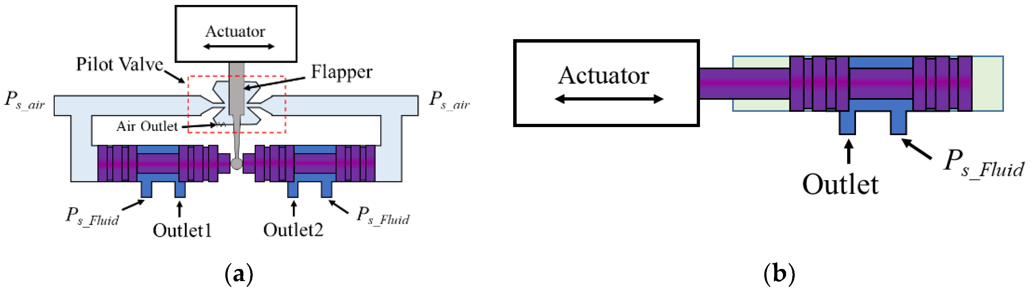
As is well known, the spool valve is the most widely used valve for hydraulic servo systems to control the flow rate and pressure drop, which are proportional to the spool displacement. The spool-valve system can be classified into single and two-stage valves. Figure 1 shows the schematic configuration of each valve system. In the two-stage valve, the air pressure is used to minimize the operating force [9]. As shown in Figure 1a, air pressures (Ps_air) are always applied on the end of the spools and the flapper can control the air pressure by preventing air flow. When one air flow is prevented, the air pressure is increased. Finally, the spool can move according to the pressure change. The input pressure of the hydraulic oil (Ps_Fluid) is applied and the area of the outlet port is changed by movement of the spool. This means that the small actuating force acting on the pilot is converted into a large actuating force for the spool [10]. A solenoid actuator is generally used for the pilot to generate the actuating force for the flapper. The flow rate can be controlled in a wide range using the two-stage spool valve. However, it has a low operating frequency (lower than 50 Hz) because of the inertia of the flapper [11]. The single-stage valve has been studied since the 1990s, as it can solve the problems of the two-stage valve [12,13]. Because an actuator directly controls the spool, the single-stage valve requires a large actuating force but has a wide range of operating frequencies. It is natural that the actuator affects the performance of the valve. Hence, many types of actuators have been applied for single-stage valves. Currently, the solenoid-type actuator is the most widely used for valve control systems, but it has the disadvantage of a slow response [14,15]. Furthermore, an advanced actuator capable of operating sufficiently quickly at high temperatures is needed in many industrial applications. One solution to these problems involves using piezoelectric actuators in the hydraulic servo valve.
Piezoelectric materials are actively studied and applied in various fields because of their many advantages, such as their fast response, high power density, and infinite resolution [16]. The piezoelectric actuator is advantageous for driving a hydraulic servo valve system [17,18]. Hence, single-stage valves using piezoelectric actuators have been studied [19,20,21,22]. Jeon et al. designed a single-stage valve system actuated using a piezostack actuator [23,24]. The performance of the valve system was evaluated via a simulation and an experiment conducted at room temperature. However, using piezoelectric actuators for high-temperature applications is difficult because they have a low Curie temperature of 150 °C. Choi et al. studied the dynamic characteristics and position-control performance of a piezostack actuator at high temperatures up to 180 °C [25]. They found that the piezoelectric stack actuator could be operated at a high temperature, but both the displacement and blocking force rapidly degraded, as expected. Jeon et al. proposed a direct-drive valve system actuated using a piezostack subjected to high temperatures [26]. The valve system was evaluated at 100 °C, but the piezostack has a high operating temperature property because it is specially made for high-temperature applications; thus, an operating temperature of 120 °C was ensured. However, normal (or general) piezostacks used in hydraulic systems can be widely applied under 60 °C to guarantee high control performance. In fact, the use of normal piezostacks for hydraulic applications subjected to high temperatures is a challenge since the precise flow-rate control performance rapidly degrades when the operating temperature is over the Curie temperature of the piezoelectric actuator.
Consequently, the challenges and contributions associated with this specific control problem are summarized as follows: (i) a normal piezostack actuator frequently used at room temperature is applied to the proposed piezostack actuator direct-drive valve (PADDV) system and subjected to a high operating temperature and high exciting frequency to examine its control performances at high temperatures. This is challenging since a minor mistake in the adjustment of the high temperature causes permanent damage to the actuator. In this work, several preliminary tests are undertaken by increasing the temperature with a fine resolution to determine the maximum operating temperature which is allowed to apply the piezostack actuator without failure; (ii) a proportional–integral–derivative (PID) feedback controller is designed and integrated with a fuzzy algorithm considering the changes of the operating frequency and temperature. The control gains are tuned using an empirical fuzzy rule with the input frequency and temperature. The choice of appropriate fuzzy variables is crucial to achieve high control performance at high temperatures; (iii) the control performances of the PADDV are experimentally observed in the heat chamber. In this study, the displacement of the spool is selected as a control variable because it is directly related to the flow rate of the spool valve. Hence, the performance of the valve system is evaluated by controlling the spool displacement. The displacement control of the spool is investigated with different frequencies up to 200 Hz and different temperatures up to 150 °C. The tests are undertaken without and with partial insulation of the piezostack using the aerogel.
2. Structure of Direct-Drive Valve
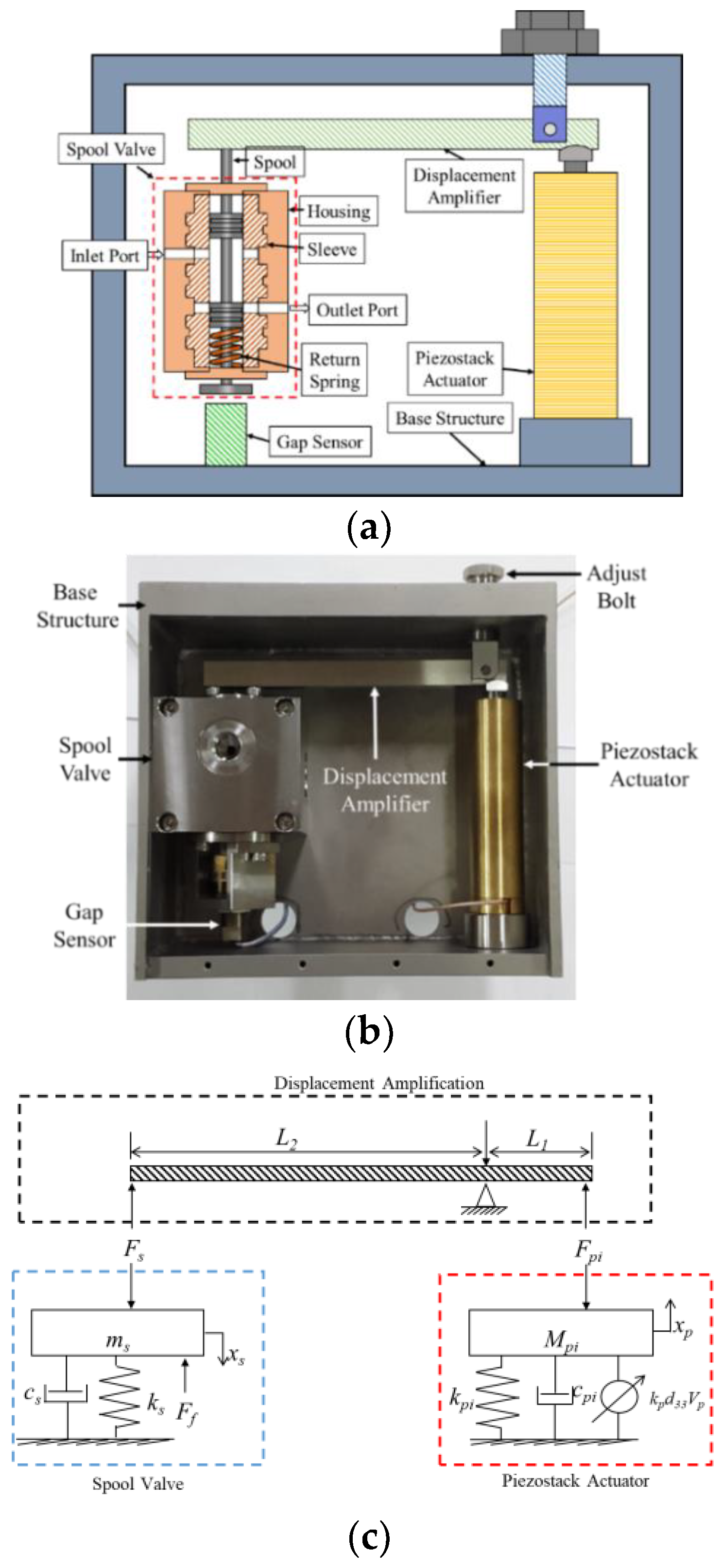
In this study, a direct-drive valve (DDV) system actuated using a piezostack is developed to provide high precision, a fast response, and reliability. Figure 2a shows the schematic of the PADDV valve system. The valve system comprises a piezostack actuator, a displacement amplifier, a spool valve, a gap sensor, an adjust bolt, and a base structure. The small displacement, which is one of the drawbacks of the piezostack actuator, is overcome using a displacement amplifier. The amplifier, with the help of a lever-hinge mechanism, can be used to magnify the displacement generated by the piezostack. A spool valve is used to control the flow rate because the valve can linearly regulate the flow rate through the position of the spool. As shown in Figure 2a, the spool valve comprises a housing, a sleeve, a spool, and a return spring. The housing and sleeve have inlet and outlet ports. The inlet port is always open and has a circular shape to maintain a uniform input pressure, regardless of the spool displacement. However, the outlet port is normally closed and has a rectangular shape to maintain linearity between the spool displacement and the flow rate. The return spring is used to return the spool to the initial position because the considered piezostack is a unipolar piezoelectric actuator. The position of the spool is controlled using the piezostack actuator, with the help of the displacement amplifier. Figure 2b shows the manufactured PADDV valve system.
Figure 2c shows a schematic of the mathematical model of the proposed valve system. The dynamic equations of the proposed valve system can be obtained with the displacement of the piezostack actuator (xp) and spool (xs) as follows:
FS can be obtained as follows:
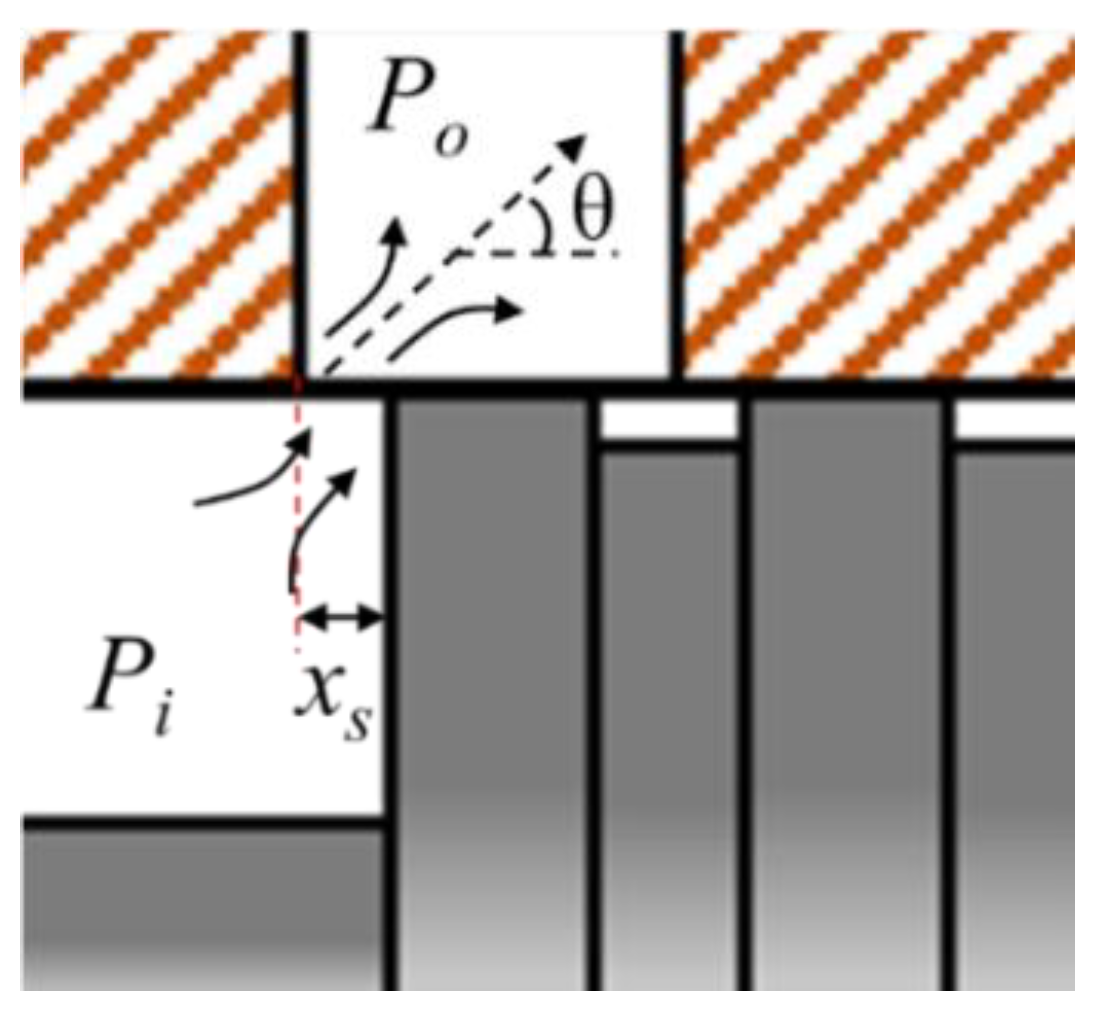
Figure 3 shows the hydraulic model of the spool valve. The pressure drop is generated between the input pressure (Pi) and output pressure (Po) with jet angle (θ). The pressure drop causes a force to push the spool, and this is called the flow force. Ff represents the steady flow force, which is calculated as follows:
Cd is a function of the cavitation number and Reynolds number and is selected in the range of 0.6 to 0.65 [20].
Finally, the dynamic equation of the PADDV system can be written as follows:
The flow rate of the spool valve can be calculated as directly related to the open area as follows:
In this study, VG 46 is used as the actuating fluid, having the density ρ = 879 kg/m3.
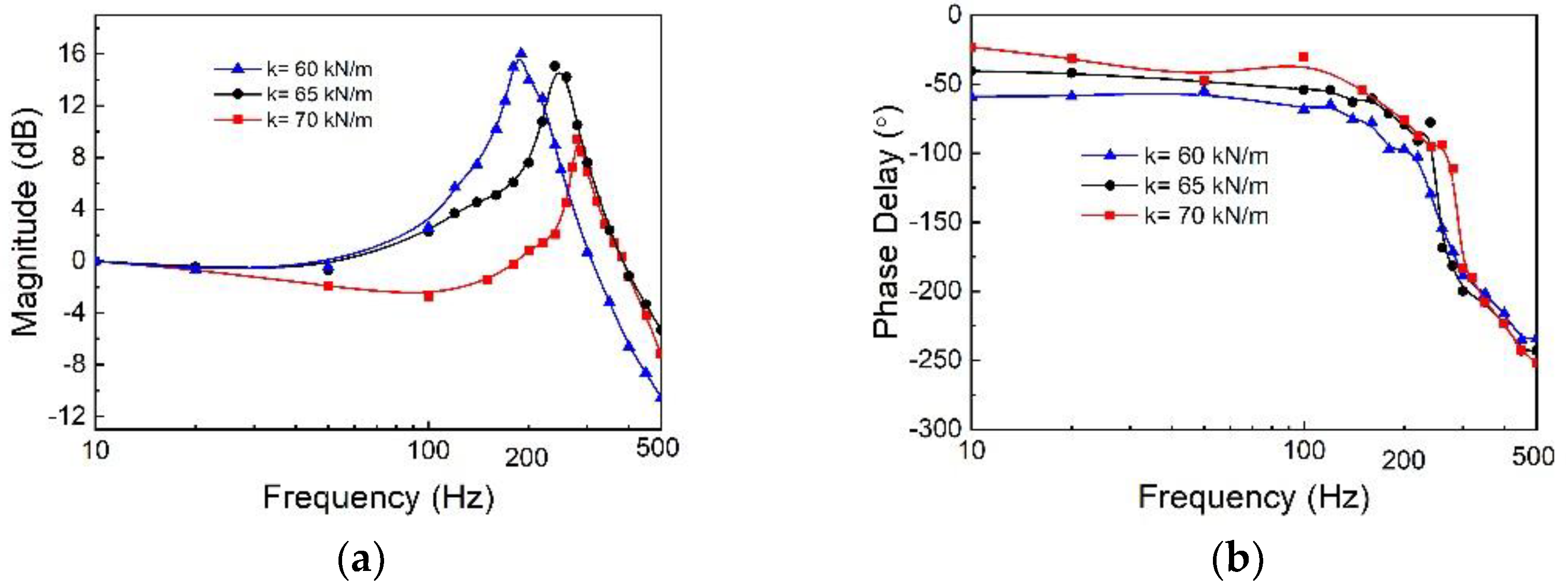
To select the spring coefficient of the return spring, the valve system is operated from 10 to 500 Hz. Four return springs with different stiffnesses are tested to determine the spring constant for the spool-valve system. Figure 4 shows the experimental results for the magnitude and phase delay in the frequency domain with difference stiffnesses of the return springs. The sinusoidal signal is applied, and the maximum and minimum displacement are measured to calculate the magnitude. The magnitude can be obtained as follows:
where ymax and ymin are the maximum and minimum displacement of the spool with actuating frequency (f), respectively. These are the maximum and the minimum displacement of the spool at 10 Hz. In this study, the piezostack valve system can be employed at operating frequencies up to 200 Hz. As shown in the figure, the springs with stiffness of 60 and 65 kN/m have resonance frequencies extremely close to 200 Hz. Hence, a spring with 70 kN/m of stiffness is selected for the valve system. Table 1 and Table 2 list the mechanical properties of the piezostack and manufactured PADDV, respectively.
3. Thermal Effect on Valve Performance
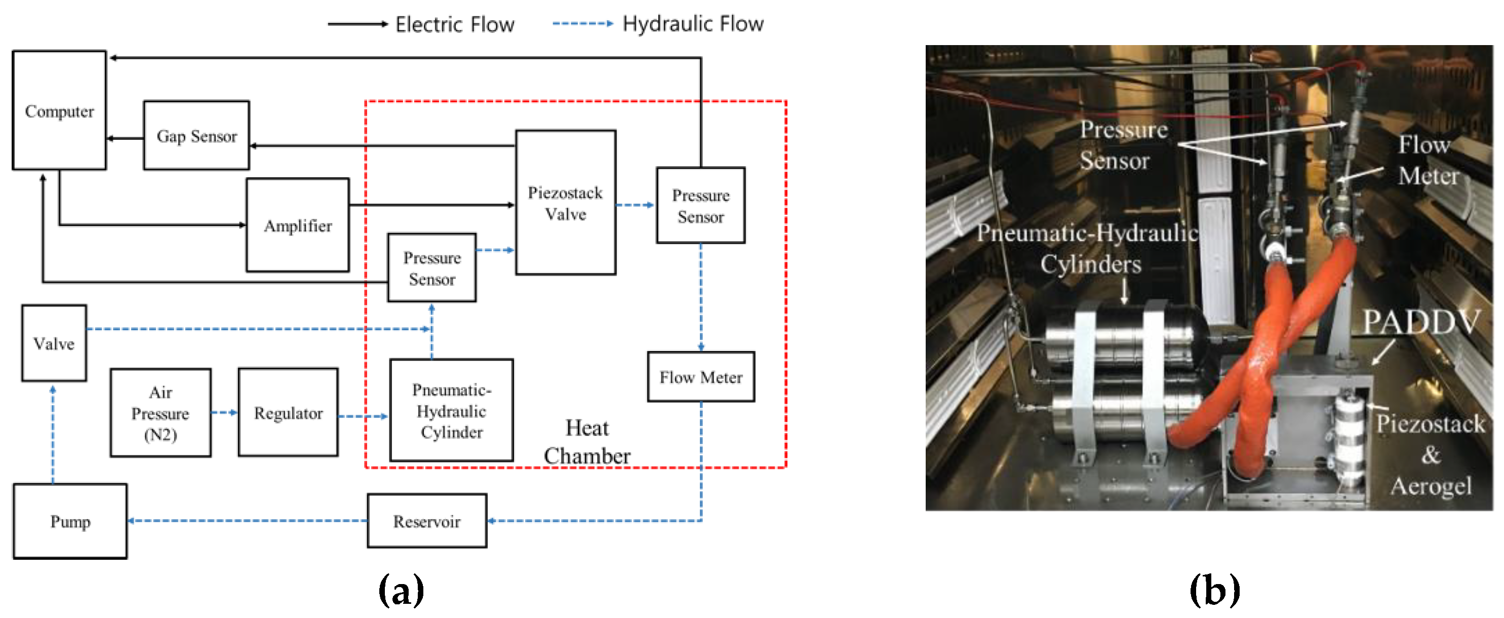
To evaluate the control performances of the proposed valve system and controller under high-temperature conditions, an apparatus is used together with a large heat chamber. Figure 5a shows the schematic configuration of the experimental flow chart. The temperature is regulated by the heat chamber (BK-HTDO-8100, Bookwang Tech Co., Gyeonggi-do, Korea) to obtain the required experimental conditions, and the air temperature can be controlled between room temperature and 300 °C. First, an electric apparatus is constructed using a computer and sensors. The signals obtained from the sensors are saved, and the input signal is generated using a computer with the help of analog-to-digital converters (AD/C) and digital-to-analog converters (DA/C) (DS1104 R&D Controller Board, dSPACE, Paderborn, Germany). A voltage amplifier (EC750SA, NF Corporation, Yokohama, Japan) is used to amplify the input signal obtained from the computer and is applied to the piezostack up to 150 V. A gap sensor (KD-2306 2SMT, KAMAN, Bloomfield, CT, USA) is used to detect the spool displacement, and the position data are transferred to the computer. Secondly, the hydraulic part is set up to generate the pressure drop. The initial pressure is generated by a nitrogen pressure vessel, and the pressure is changed to the hydraulic pressure using the pneumatic–hydraulic cylinder. The cylinder has a hydraulic volume of 1 L, and three cylinders are used for the experiment. Two pressure sensors (210-40-011-04, Paine Electronics, LLC, East Wenatchee, WA, USA) are placed in the inlet and outlet ports of the valve system. A flow meter (FT-08AEYB-LEA-3, Flow Technology Inc., Tempe, AZ, USA) is used to detect the flow rate of the hydraulic fluid. The sensors and the piezostack valve system are located in the heat chamber. The piezostack is insulated from the heat using an aerogel. Figure 5b shows an image of the experimental apparatus inside the heat chamber. In this study, the piezostack actuator is made of lead–zirconate–titanate (PZT) ceramic. The maximum operating temperature of the piezostack used with the PZT materials is 80 °C, which is approximately half the Curie temperature, as the used PZT ceramic has a Curie temperature of 150 °C. The operating temperature in this study is 150 °C. Hence, the spool displacement of the valve system is first evaluated considering the effect of heat. The force generated by the PZT piezostack actuator decreases as the temperature increases.
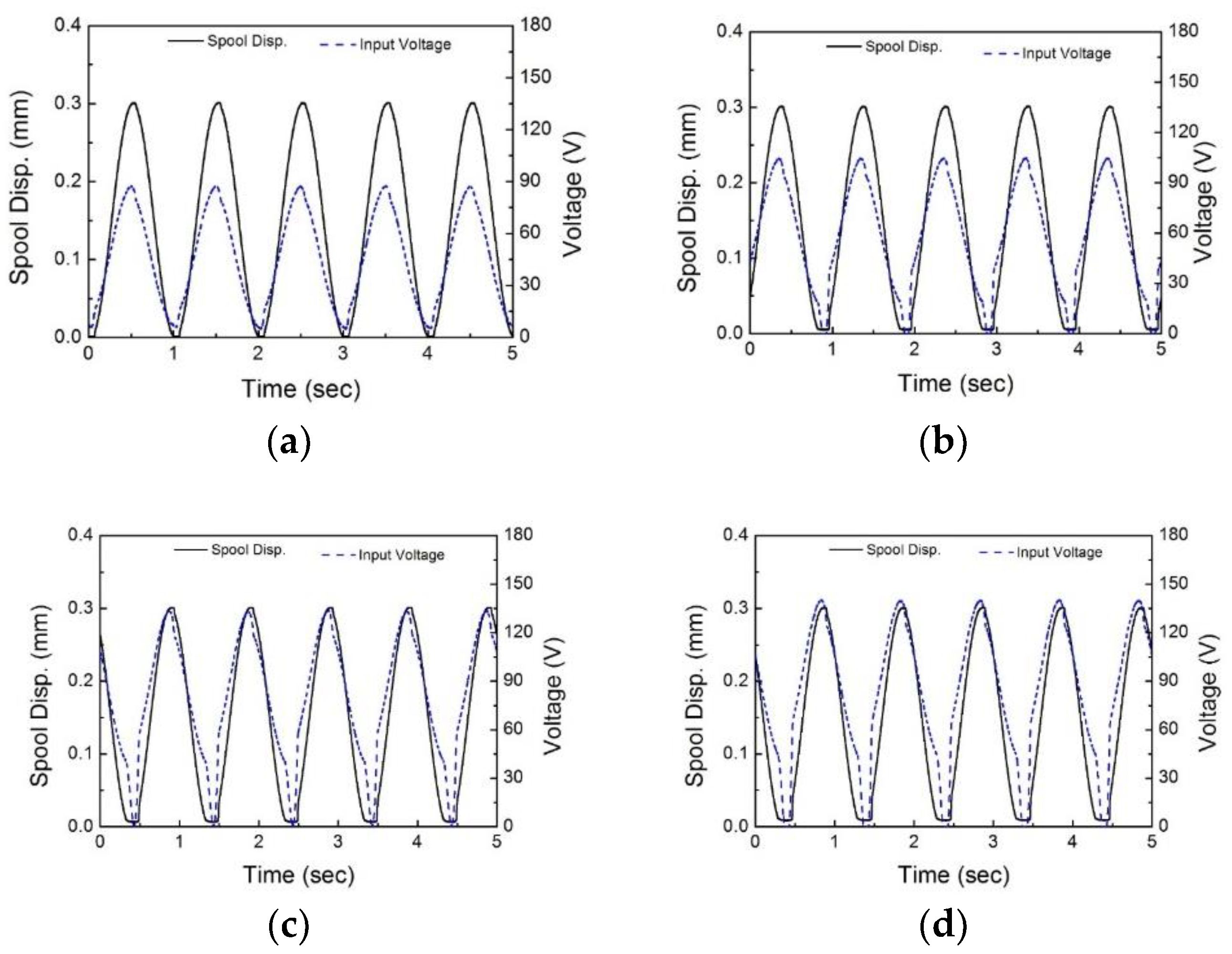
Figure 6 shows the input voltage required to obtain a spool displacement of 0.3 mm. To control the displacement of spool, a traditional PID controller is used. The P, I, and D gains are chosen via the trial-and-error method. To evaluate the heat influence, the temperature of the piezostack actuator is increased from 30 to 120 °C. As shown in Figure 6a, an input voltage of 90 V yields a spool displacement of 0.3 mm. However, the input voltage is increased by increasing the temperature, as shown in Figure 6b–d. At 120 °C, an input voltage of 147 V is needed to obtain a spool displacement of 0.3 mm. The spool cannot reach the desired position when the temperature of the piezostack actuator is above 120 °C. This implies that the actuating performance of the piezostack significantly decreases and the possibility of permanent damage to the piezostack increases.
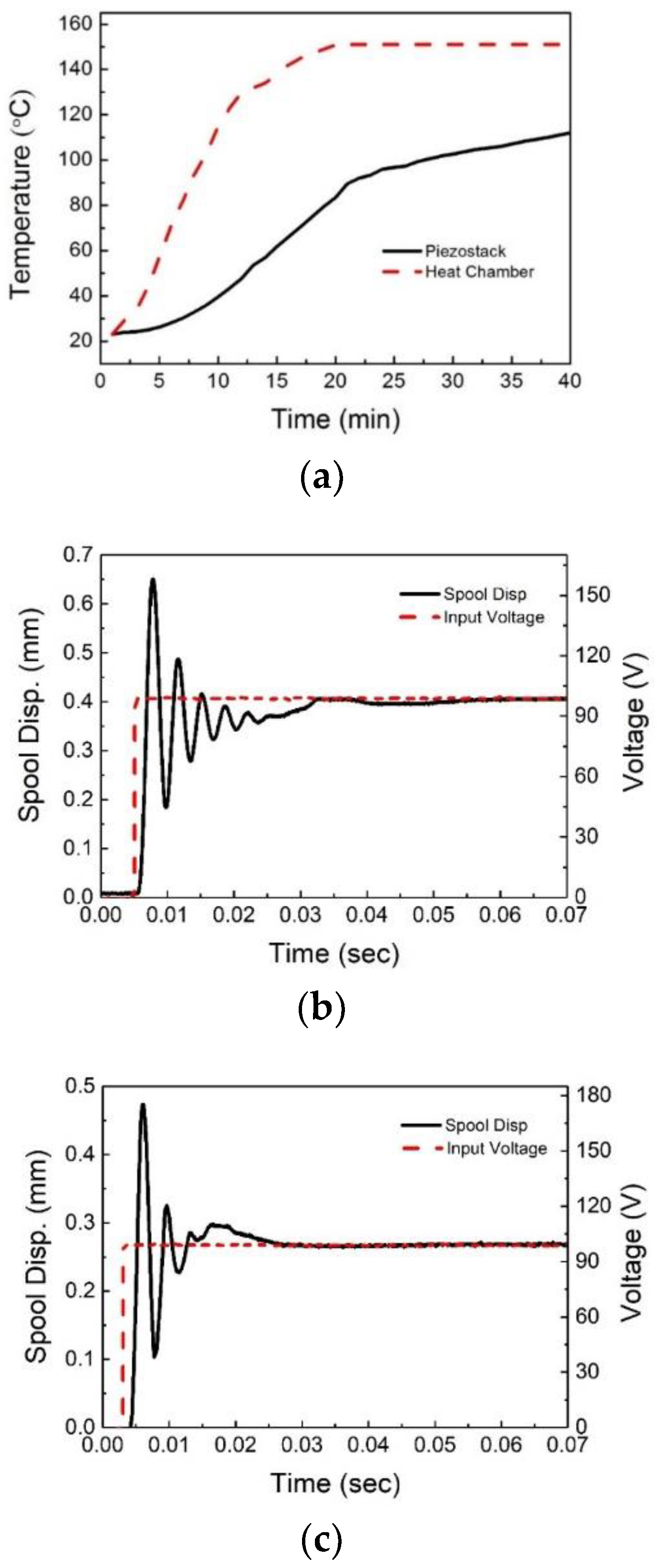
Hence, in this study, the piezostack is insulated using an aerogel, i.e., a synthetic porous material, to prevent the piezostack from being permanently damaged because of the high-temperature air (150 °C) inside the heat chamber. Figure 7a shows the temperature variations in the heat chamber and in the piezostack actuator with the heat insulator. As indicated by the results, the temperature inside the heat chamber is 150 °C after 20 min of heating, and the temperature of the piezostack has increased to 112 °C after 40 min.
The step response of the valve system using the chosen return spring is observed with an input voltage of 100 V without controlling the room or high-temperature conditions. The time constant, which is 63.2% of its final value, is measured using the step input. Figure 7b,c show the results of the step-response test conducted at room temperature and at 150 °C. The time constant of the valve system is 1.6 ms, and the generated spool displacement is 0.41 mm at room temperature. At the high temperature, the time constant and final displacement of the system are 1.8 ms and 0.27 mm, respectively; moreover, the time constant slightly increases and the generated pool displacement decreases because the stiffness of the piezostack actuator decreases.
4. Control Responses
The piezostack is influenced by heat; thus, the properties of the piezostack such as the blocking force, displacement, and hysteresis change. This implies that the piezostack is a temperature-dependent, nonlinear system. Therefore, a fuzzy algorithm is used to control the system at various temperatures, because a fuzzy controller can control a nonlinear system. Furthermore, the fuzzy controller does not require a precise mathematical model. The fuzzy logic is far closer to human language than traditional logical systems and can process ambiguous input values such as warm and cold. The fuzzy logic can convert the linguistic strategy into an automatic control strategy on the basis of expert knowledge. The expert knowledge yields better results than conventional control logic. In particular, the methodology of the fuzzy logic controller (FLC) is very useful in cases of complex calculations for qualitative, inexact, or uncertain interpretations. The FLC comprises two essential parts: a set of linguistic control rules and a compositional rule of inference. In this study, a PID controller which can change gains automatically using a fuzzy algorithm is designed.
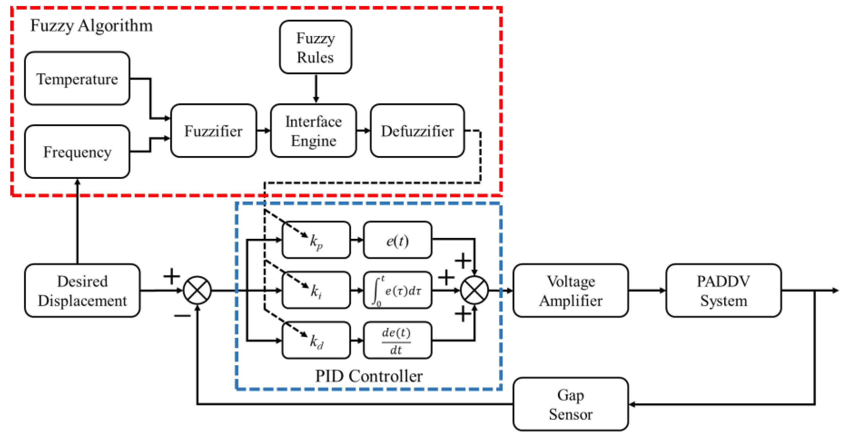
Figure 8 shows a schematic of the PID controller together with the fuzzy algorithm. The PID controller has a feedback mechanism, which is commonly used in industrial fields. In the PID controller, an error (e(t)) between the desired and actual output values is used. This error is then applied for the correction based on the proportional, integral, and derivative terms. The normal PID controller is expressed as follows:
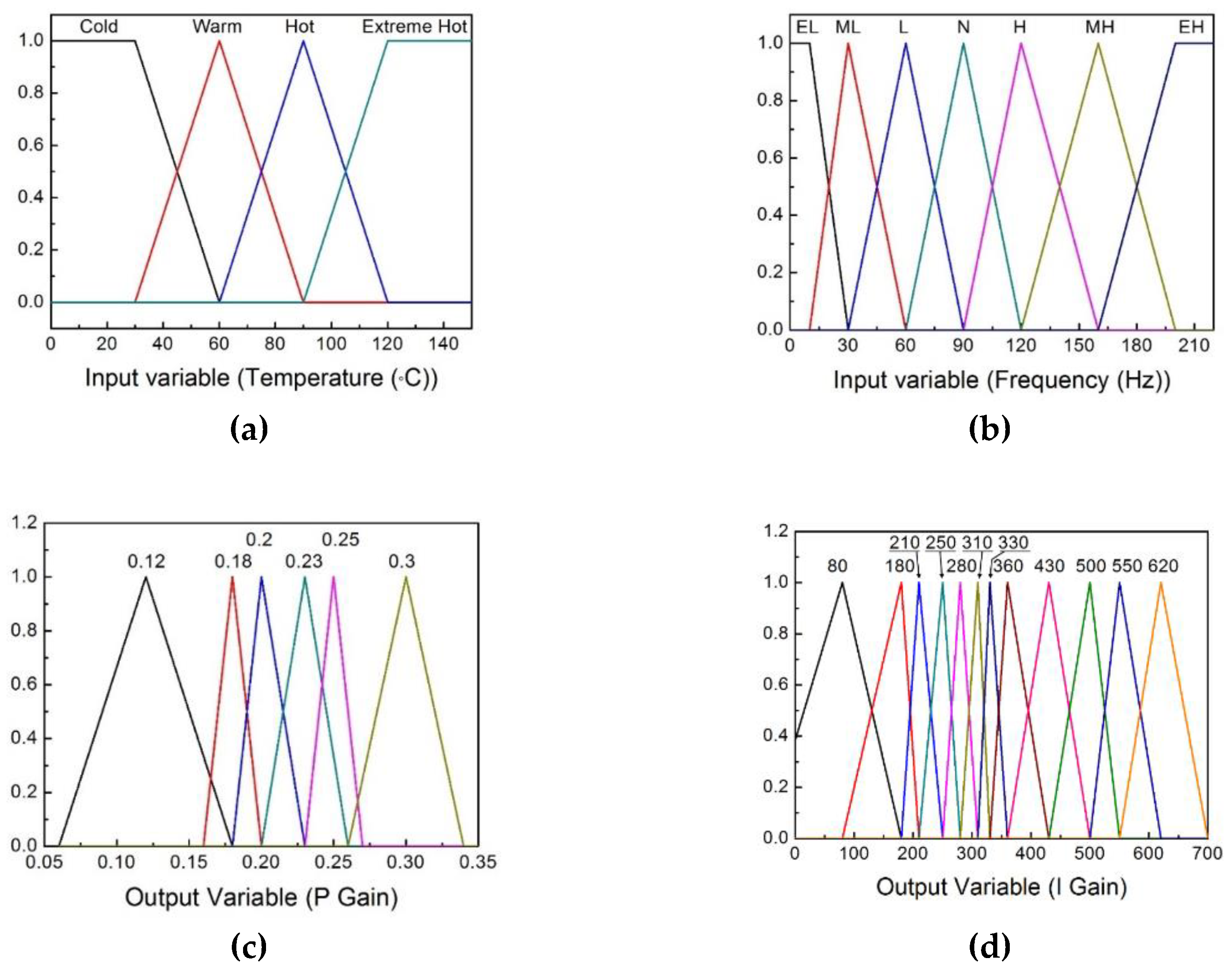
However, the PADDV system is a temperature-dependent system because the properties of the piezostack actuator change based on the temperature, as previously mentioned. Therefore, the gains of the PID controller must be changed to control the valve system at various temperatures. The fuzzy algorithm has two input and two output variables. The inputs are the temperature and operating frequency, and the outputs are the kp and ki gains, which are the gains of the PID controller. Figure 9 shows the membership functions of the input and output variables. In this research, a triangular fuzzy number is used because the method has a low calculation amount compared with other method such as trapezoidal, bell-shaped, non-convex, etc. As shown in Figure 9a,b, the temperatures and frequencies are classified as “cold”, “warm”, “hot”, and “extreme hot” and “extreme low”, “medium low”, “low”, “normal”, “high”, “medium high”, and “extreme high”, respectively. The figures show the range of each value and perform the function of the fuzzification of the input temperature and frequency. This can provide necessary definitions to define linguistic control rules. Table 3 and Table 4 list the fuzzy inference rule between the input and the output, and the rules are determined by many experimental results. The input membership functions and the fuzzy rules can provide necessary definitions to define the linguistic control rules. Figure 9c,d show the membership functions of the output variables; from those, the gains of the PID controller are determined. In other words, the figures perform the function of the defuzzification and provide control gains.
In this study, the center-average defuzzification method is used to calculate the output value, which is defined as follows [27]:
where c, ci, and µc are the output value, the center value of the i-th output membership function, and the product rule, respectively. Equation (7) can be rewritten as follows:
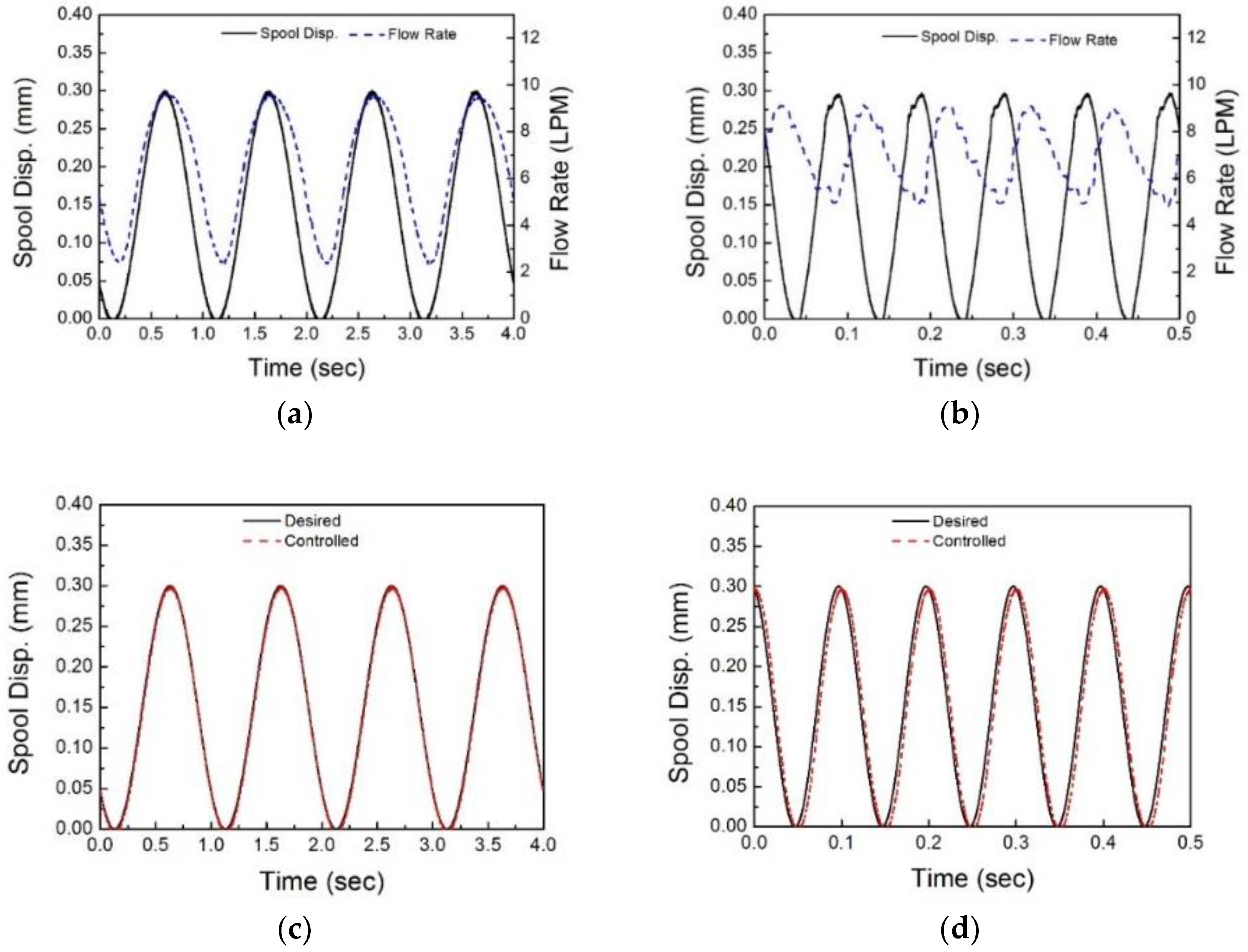
kp and ki are re-expressed using Equation (8). kd is determined as 0.0001 according to the experimental results. To evaluate the proposed valve performance, the flow rate is first evaluated using the spool displacement. Figure 10a,b show the experimental results for the flow rate at room temperature for each frequency. Errors are observed in the flow-rate data below 3.78 Lpm (liter per minute) because the flow meter can only detect flow rates ranging from 3.78 to 37.8 Lpm. The flow-rate data properly follow the displacement of the spool, although the sensor exhibits an error at low flow rates, as shown in Figure 10a. However, a large error is observed in the flow-rate data obtained from the flow meter with a time delay, as shown in Figure 10b, because the flow meter and indicator (LA-5-A-V1F1, Flow Technology Inc., Tempe, AZ, USA) have time delays of 4 and 20 ms, respectively. Therefore, in this work, the displacement of the spool is selected as the control target because the flow rate is directly related to the spool displacement; the flow rate can be calculated using the spool displacement and properties of hydraulic oil with temperatures according to Equation (5). It is noted here that the response time of the flow meter is not sufficient to deal with the fast motion between the input and output (about 200 Hz). This is the reason why the gap sensor is used to measure the spool displacement. Figure 10c,d show the control results obtained at room temperature using the normal PID controller. As shown in the figure, the displacement of the spool follows the desired displacement at operating frequencies of 1 and 10 Hz. The same PID gains are observed in the results, which are 0.12, 80, and 0.0001 for the P, I, and D gains, respectively. However, the gains differ at 200 Hz: 0.3, 620, and 0.0001 for P, I, and D, respectively.
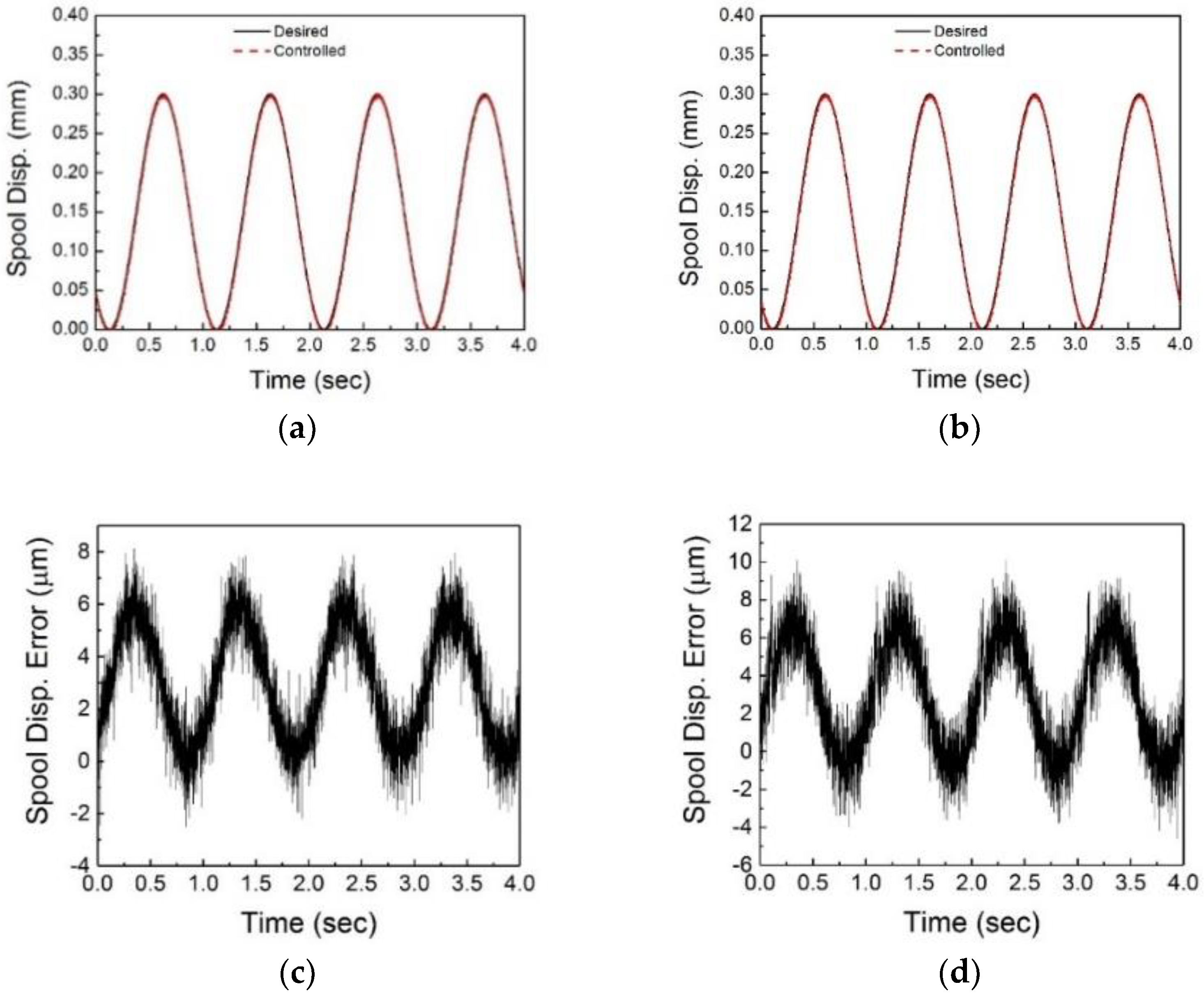
Figure 11 shows the control results obtained at room and high temperature using the fuzzy PID controller. As shown in Figure 11a,b, the performance results obtained at the frequencies of 1 Hz are similar to those of the normal PID controller operating at a high temperature. The tracking error increases at high temperatures because the heat affects the system, as shown in Figure 11c,d.
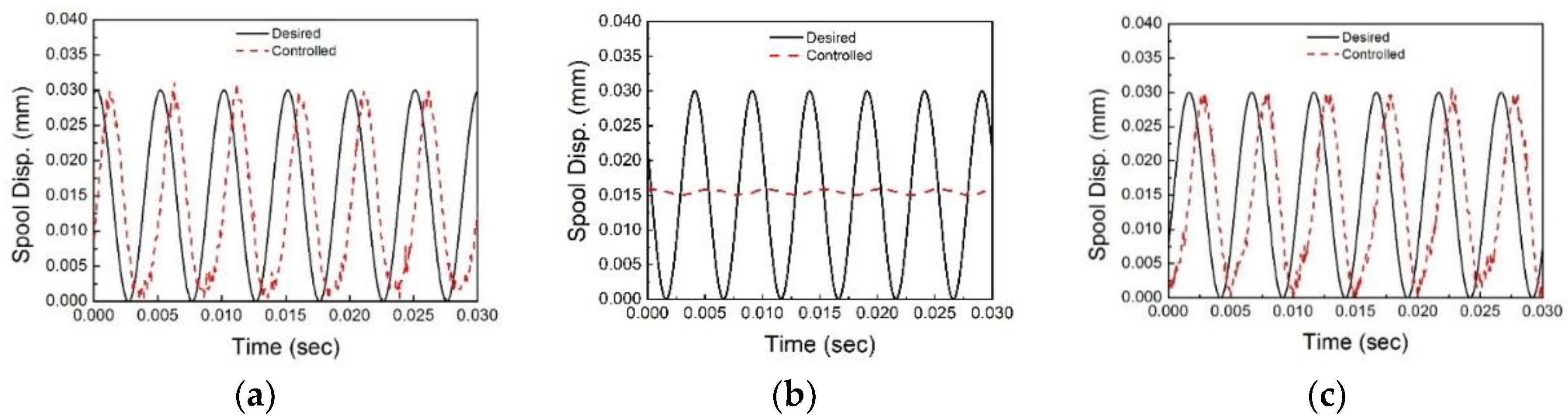
Figure 12 shows the control results of the spool displacement at 200 Hz. Figure 12a represents the tracking control results with respect to the room temperature. As shown in the figure, the result shows a time delay of 75.6°. Although this time delay is considerable, the spool can follow the desired displacement. At 200 Hz, the P, I, and D gains are 0.3, 620, and 0.0001, respectively. Figure 12b shows the displacement–control result at 150 °C with the same PID gains. The spool displacement cannot respond at an operating frequency of 200 Hz and a high temperature using the same PID gains. The valve system with the fuzzy PID controller has largely the same performance at 200 Hz without gain tuning, as shown in Figure 12c. The gains are automatically tuned according to the frequency and temperature. The time delay increases from 75.6° to 79.2° because the stiffness of the return spring decreases owing to the heat. However, the system remains stable in a certain range because the phase delay is below 180°.
5. Conclusions
In this work, the piezostack actuator direct-drive valve (PADDV) system was designed and its control performance was evaluated at high temperatures. An experimental apparatus was constructed using a heat chamber and high-temperature resistant sensors for testing the valve system at high temperatures. The step response of the valve system was analyzed using the return spring at high temperature with a step input voltage. It has been observed that the time constant is increased as the displacement of the spool is decreased. In order to evaluate the spool tracking performance, both a classical PID controller and PID controller integrated with a fuzzy algorithm was designed and implemented in the valve system, which was subjected to temperatures up to 150 °C. The results achieved from the control realization are summarized as follows.
The PID controller can be used to control the valve system up to a frequency of 200 Hz at room temperature. However, the valve system cannot be controlled using the same gains under the frequency variation. Therefore, a fuzzy algorithm was applied to tune the gains according to the temperature and operating frequency. The performance of the system is satisfactory at low frequencies and between room temperature and 150 °C. The valve system exhibits the time delay at frequency of 200 Hz for the entire temperature range because the stiffness of the return spring is designed considering high-temperature conditions. Although the system exhibits a time delay, the spool performance which follows the desired displacement is satisfactory.
The results of this study show that the PADDV with the thermal insulation using the general piezostack actuator can be practically used to control the flow rate at various high operating temperatures required in many components or systems. However, for successful practical application, the durability of the valve system using the piezostack actuator at high temperatures over long operating periods should be investigated thoroughly. Such a study will be conducted in the near future.
Nomenclature
| xp | Displacements of the piezostack |
| xs | Displacements of the spool |
| Vpi | Input voltage |
| mpi | Mass of the piezostack |
| cpi | Equivalent damping coefficient of the piezostack |
| kpi | Stiffness of the piezostack |
| d 33 | Charge constant of the piezostack |
| ms | Mass of the spool |
| cs | Damping coefficient of the spool |
| ks | Stiffness of the spool |
| Fpi | Force exerted by the piezostack |
| Fs | Force transmitted from the displacement magnification device |
| dr | Amplification ratio of the displacement amplifier |
| IL | Mass moment of inertia of the lever |
| Angular acceleration of the lever | |
| Pressure drop | |
| Cd | Drag coefficient |
| Jet angle | |
| A 0 | Open area of the outlet port |
| Ds | Diameter of the spool |
| Hs | Height of the outlet port |
| QS | Flow rate |
| ρ | Density of the hydraulic oil |
Author Contributions
C.H. and S.C. conceived and designed the experiments; C.H. and Y.H. performed the experiments; C.H. and Y.H. analyzed the data; C.H. and S.C. wrote the paper.
Funding
This work was supported by the National Research Foundation of Korea (NRF) grant funded by the Korea government (MEST) (No. 2017R1A2B3003026). This financial support is gratefully acknowledged.
Conflicts of Interest
The authors declare that there is no conflict of interest.
References
- Rabie, M.G. Fluid Power Engineering; McGraw-Hill: New York, NY, USA, 2009; ISBN 0071834974/9780071834971. [Google Scholar]
- Majumdar, S.R. Oil Hydraulic Systems: Principles and Maintenance; McGraw-Hill: New York, NY, USA, 2002; ISBN 0071204059/9780071204057. [Google Scholar]
- Laser, D.J.; Santiago, J.G. A review of micropumps. J. Micromech. Microeng. 2004, 14, R35. [Google Scholar] [CrossRef]
- Moir, I.; Seabridge, A. Aircraft Systems: Mechanical, Electrical, and Avionics Subsystems Integration; John Wiley & Sons: Hoboken, NJ, USA, 2011; Volume 52. [Google Scholar]
- McRuer, D.T.; Graham, D.; Ashkenas, I. Aircraft Dynamics and Automatic Control; Princeton University Press: Princeton, NJ, USA, 2014. [Google Scholar] [CrossRef]
- Nam, Y.; Hong, S.K. Force control system design for aerodynamic load simulator. Control Eng. Pract. 2002, 10, 549–558. [Google Scholar] [CrossRef]
- Rogers, J.; Costello, M. Design of a roll-stabilized mortar projectile with reciprocating canards. J. Guid. Control Dyn. 2010, 33, 1026–1034. [Google Scholar] [CrossRef]
- Siouris, G.M. Missile Guidance and Control Systems; Springer: Berlin, Germany, 2004. [Google Scholar]
- Liu, C.; Jiang, H. A seventh-order model for dynamic response of an electro-hydraulic servo valve. Chin. J. Aeronaut. 2014, 27, 1605–1611. [Google Scholar] [CrossRef]
- Kim, D.H.; Tsao, T.C. A linearized electrohydraulic servovalve model for valve dynamics sensitivity analysis and control system design. J. Dyn. Syst. 2000, 122, 179–187. [Google Scholar] [CrossRef]
- Changbin, G.; Zongxia, J. A piezoelectric direct-drive servo valve with a novel multi-body contacting spool-driving mechanism: Design, modelling and experiment. Proc. Inst. Mech. Eng. Part C J. Mech. Eng. Sci. 2014, 228, 169–185. [Google Scholar] [CrossRef]
- Tao, J.F.; Jin, L.S.; Xu, L.; Liu, C.L. Load control of electrically controlled hydraulic pump’s flow/pressure characteristics testing with direct drive servo-proportional valve. In Proceedings of the 2010 IEEE/ASME International Conference on Advanced Intelligent Mechatronics, Montreal, QC, Canada, 6–9 July 2010; pp. 1374–1379. [Google Scholar]
- Amirante, R.; Moscatelli, P.G.; Catalano, L.A. Evaluation of the flow forces on a direct (single stage) proportional valve by means of a computational fluid dynamic analysis. Energy Convers. Manag. 2007, 48, 942–953. [Google Scholar] [CrossRef]
- Paul, A.K.; Mishra, J.E.; Radke, M.G. Reduced order sliding mode control for pneumatic actuator. IEEE Trans. Control Syst. Technol. 1994, 2, 271–276. [Google Scholar] [CrossRef]
- Li, S.; Song, Y. Dynamic response of a hydraulic servo-valve torque motor with magnetic fluids. Mechatronics 2007, 17, 442–447. [Google Scholar] [CrossRef]
- Choi, S.B.; Han, Y.M. Piezoelectric Actuators: Control Applications of Smart Materials; CRC Press: New York, NY, USA, 2010. [Google Scholar]
- Ullmann, A. The piezoelectric valve-less pump—Performance enhancement analysis. Sens. Actuators A Phys. 1998, 69, 97–105. [Google Scholar] [CrossRef]
- Sobocinski, M.; Juuti, J.; Jantunen, H.; Golonka, L. Piezoelectric unimorph valve assembled on an LTCC substrate. Sens. Actuators A Phys. 2009, 149, 315–319. [Google Scholar] [CrossRef]
- Lindler, J.E.; Anderson, E.H. Piezoelectric direct drive servovalve. In Proceedings of the Smart Structures and Materials 2002: Industrial and Commercial Applications of Smart Structures Technologies, San Diego, CA, USA, 9 July 2002; Volume 4698, pp. 488–497. [Google Scholar]
- Zhou, M.; Tian, Y.; Yang, Z.; Cheng, G.; Shiju, E. Control of a new type of direct drive piezoelectric servo valve. In Proceedings of the IEEE International Conference on Robotics and Biomimetics, Shenyang, China, 22–26 August 2004; pp. 795–798. [Google Scholar]
- Zhou, M.L.; Yang, Z.G.; Gao, W.; Tian, Y.T.; Shen, C.L.; Li, P. Fuzzy control of a new type of piezoelectric direct drive electro-hydraulic servo valve. In Proceedings of the Advances in Machine Learning and Cybernetics: 4th International Conference, Guangzhou, China, 18–21 August 2005; Volume 2, pp. 819–824. [Google Scholar]
- Sente, P.; Vloebergh, C.; Labrique, F.; Alexandre, P. Control of a direct-drive servo-valve actuated by a linear amplified piezoelectric actuator for aeronautic applications. In Proceedings of the Electrical Machines ICEM 2008: 18th International Conference, Vilamoura, Portugal, 6–9 September 2008; pp. 1–6. [Google Scholar]
- Jeon, J.; Nguyen, Q.H.; Han, Y.M.; Choi, S.B. Design and evaluation of a direct drive valve actuated by piezostack actuator. Adv. Mech. Eng. 2013, 5, 986812. [Google Scholar] [CrossRef]
- Jeon, J.; Han, C.; Han, Y.M.; Choi, S.B. A new type of a direct-drive valve system driven by a piezostack actuator and sliding spool. Smart Mater. Struct. 2014, 23, 075002. [Google Scholar] [CrossRef]
- Han, C.; Jeon, J.; Chung, J.U.; Choi, S.B. Dynamic characteristics and control capability of a piezostack actuator at high temperatures: Experimental investigation. Smart Mater. Struct. 2015, 24, 057002. [Google Scholar] [CrossRef]
- Jeon, J.; Han, C.; Chung, J.U.; Choi, S.B. Performance evaluation of a piezoactuator-based single-stage valve system subjected to high temperature. Smart Mater. Struct. 2014, 24, 015022. [Google Scholar] [CrossRef]
- Lee, C.C. Fuzzy logic in control systems: Fuzzy logic controller. I. IEEE Trans. Syst. Man Cybern. 1990, 20, 404–418. [Google Scholar] [CrossRef]
Figure 1.
Schematic configuration of a valve system. (a) Basic working principle of two-stage valve, (b) Basic working principle of Single-stage valve.
Figure 1.
Schematic configuration of a valve system. (a) Basic working principle of two-stage valve, (b) Basic working principle of Single-stage valve.

Figure 2.
The proposed piezostack actuator direct-drive valve (PADDV) system. (a) Schematic configuration of PADDV, (b) Photograph image of the manufactured PADDV, (c) Mechanical model of proposed PADDV.
Figure 2.
The proposed piezostack actuator direct-drive valve (PADDV) system. (a) Schematic configuration of PADDV, (b) Photograph image of the manufactured PADDV, (c) Mechanical model of proposed PADDV.

Figure 3.
Hydraulic model of the spool valve.

Figure 4.
Frequency response of the return spring with different stiffnesses: (a) Magnitude, (b) Phase delay.
Figure 4.
Frequency response of the return spring with different stiffnesses: (a) Magnitude, (b) Phase delay.

Figure 5.
The flow chart and photograph of the experimental apparatus. (a) Experimental flow chart for the electric and hydraulic flow (b) PADDV installed in inside of the heat chamber.
Figure 5.
The flow chart and photograph of the experimental apparatus. (a) Experimental flow chart for the electric and hydraulic flow (b) PADDV installed in inside of the heat chamber.

Figure 6.
Influence of heat on the spool displacement without control action. (a) 30 °C, (b) 90 °C, (c) 110 °C, (d) 120 °C.
Figure 6.
Influence of heat on the spool displacement without control action. (a) 30 °C, (b) 90 °C, (c) 110 °C, (d) 120 °C.

Figure 7.
Temperature variation and step responses of the valve system, (a) Temperature variation, (b) Step response at 30 °C, (c) Step response at 150 °C.
Figure 7.
Temperature variation and step responses of the valve system, (a) Temperature variation, (b) Step response at 30 °C, (c) Step response at 150 °C.

Figure 8.
Schematic of the fuzzy PID(proportional-integral-derivative) controller.

Figure 9.
Membership functions, (a) Temperature input, (b) Frequency input, (c) P gain output, (d) I gain output.
Figure 9.
Membership functions, (a) Temperature input, (b) Frequency input, (c) P gain output, (d) I gain output.

Figure 10.
Tracking control results via PID controller at 30 °C, (a) Results from displacement sensor and flow meter at 1 Hz (b) Results from displacement sensor and flow meter at 10 Hz (c) Tracking control at 1 Hz, (d) Tracking control at 10 Hz.
Figure 10.
Tracking control results via PID controller at 30 °C, (a) Results from displacement sensor and flow meter at 1 Hz (b) Results from displacement sensor and flow meter at 10 Hz (c) Tracking control at 1 Hz, (d) Tracking control at 10 Hz.

Figure 11.
Tracking control results via fuzzy PID controller at 1 Hz, (a) Tracking control result at 30 °C, (b) Tracking control result at 150 °C, (c) Tracking error at 30 °C, Tracking error at 150 °C.
Figure 11.
Tracking control results via fuzzy PID controller at 1 Hz, (a) Tracking control result at 30 °C, (b) Tracking control result at 150 °C, (c) Tracking error at 30 °C, Tracking error at 150 °C.

Figure 12.
Tracking control results with 200 Hz, (a) Tracking control result via PID controller at 30 °C, (b) Tracking control result via PID controller at 150 °C with same PID gains at 30 °C, (c) Tracking control result via fuzzy PID controller at 150 °C.
Figure 12.
Tracking control results with 200 Hz, (a) Tracking control result via PID controller at 30 °C, (b) Tracking control result via PID controller at 150 °C with same PID gains at 30 °C, (c) Tracking control result via fuzzy PID controller at 150 °C.


Table 1.
Mechanical properties of the piezostack actuator.
| Specification | Symbol | Value | Unit |
|---|---|---|---|
| Damping coefficient | cpi | 150 | N·s/m |
| Stiffness | kpi | 60 | MN/m |
| Mass | mpi | 0.317 | kg |
| Charge constant | d 33 | 6 × 10⁻⁷ | m/V |
| Length | lp | 0.1 | m |
| Operating temperature | 80 | °C |
Table 2.
Mechanical properties of the spool sleeve.
| Specification | Symbol | Value | Unit |
|---|---|---|---|
| Mass of spool | ms | 0.01 | Kg |
| Damping coefficient of spool | cs | 200 | N·s/m |
| Spring coefficient of return spring | ks | 70 | kN/m |
| Diameter of spool | Ds | 7.145 | mm |
| Height of outlet port | Hs | 4 | mm |
| Overlap width | ε | 0.01 | mm |
| Width of outlet port | a | 2 | mm |
| Discharge coefficient | Cd | 0.61 | |
| Jet angle | θ | 61 |
Table 3.
Fuzzy rules for P gain (kp).
| Frequency | Temperature | |||
|---|---|---|---|---|
| Cold | Warm | Hot | Extreme Hot | |
| Extreme Low | 0.12 | 0.12 | 0.12 | 0.12 |
| Medium Low | 0.12 | 0.12 | 0.12 | 0.12 |
| Low | 0.12 | 0.12 | 0.12 | 0.12 |
| Normal | 0.12 | 0.12 | 0.18 | 0.18 |
| High | 0.23 | 0.2 | 0.18 | 0.18 |
| Medium High | 0.25 | 0.2 | 0.18 | 0.2 |
| Extreme High | 0.3 | 0.2 | 0.2 | 0.2 |
Table 4.
Fuzzy rules for I gain (ki).
| Frequency | Temperature | |||
|---|---|---|---|---|
| Cold | Warm | Hot | Extreme Hot | |
| Extreme Low | 80 | 80 | 80 | 80 |
| Medium Low | 180 | 180 | 180 | 180 |
| Low | 280 | 280 | 210 | 210 |
| Normal | 310 | 310 | 250 | 250 |
| High | 430 | 360 | 330 | 280 |
| Medium High | 550 | 430 | 360 | 330 |
| Extreme High | 620 | 500 | 430 | 430 |
© 2018 by the authors. Licensee MDPI, Basel, Switzerland. This article is an open access article distributed under the terms and conditions of the Creative Commons Attribution (CC BY) license (http://creativecommons.org/licenses/by/4.0/).
Share and Cite
MDPI and ACS Style
Han, C.; Choi, S.-B.; Han, Y.-M. A Piezoelectric Actuator-Based Direct-Drive Valve for Fast Motion Control at High Operating Temperatures. Appl. Sci. 2018, 8, 1806. https://doi.org/10.3390/app8101806
AMA Style
Han C, Choi S-B, Han Y-M. A Piezoelectric Actuator-Based Direct-Drive Valve for Fast Motion Control at High Operating Temperatures. Applied Sciences. 2018; 8(10):1806. https://doi.org/10.3390/app8101806
Chicago/Turabian StyleHan, Chulhee, Seung-Bok Choi, and Young-Min Han. 2018. "A Piezoelectric Actuator-Based Direct-Drive Valve for Fast Motion Control at High Operating Temperatures" Applied Sciences 8, no. 10: 1806. https://doi.org/10.3390/app8101806
Note that from the first issue of 2016, this journal uses article numbers instead of page numbers. See further details here.