Experimental Studies on the Spraying Pattern of a Swirl Nozzle for Coal Dust Control


1
College of Mechanical Engineering, Taiyuan University of Technology, Taiyuan 030024, China
2
Shanxi Provincial Engineering Laboratory (Research Center) for Mine Fluid Control, Taiyuan 030024, China
3
Department of Engineering and Design, University of Sussex, Brighton BN1 9RH, UK
*
Author to whom correspondence should be addressed.
Appl. Sci. 2018, 8(10), 1770; https://doi.org/10.3390/app8101770
Submission received: 23 July 2018
/
Revised: 18 September 2018
/
Accepted: 21 September 2018
/
Published: 30 September 2018
Abstract
:The experimental and numerical studies were performed to understand the atomization mechanism of pressure spray of a swirl nozzle. The design and performance parameters such as spray cone angle, velocity of particles, spray pressure, and Sauter Mean Diameter (SMD) of the droplets were studied using a laser particle size analyzer and high-speed camera. The results show that the SMD increases at first, then decreases as the spray distance increases, and finally tends to be stable after 1 m. The SMD is largest in the center of the spray field and decreases gradually along the radial direction. The SMD distribution is more concentrated near the nozzle. Increasing spray pressure and deceasing nozzle diameter both can make the SMD distribution more concentrated and uniform. The swirl nozzle has been used in a coal mine and was shown to be very effective in suppressing coal dust compared to other traditional nozzles.
1. Introduction
Coal dust of the mining industry causes the number one health problem in coal miners: pneumoconiosis (black lung). Excessive coal dust in underground coal mines can also cause disastrous explosions [1,2]. Water spraying is one of the most efficient and cost-effective measures to reduce dust concentration in coal mines [3]. This method uses small water particles sprayed by a nozzle to capture the coal dust in the air. Consequently, the method to produce tiny water particles and the diameter of the water particles are important for reducing coal dust. If the diameter of water is near the diameter of coal dust, according to Wang Peng-fei [4], better dust removal can be achieved. Pang Jiewen et al. [5] had measured the coal dust particle size. The results showed that the distribution scope of the major coal dust particle size is about 10–100 μm. There are three main kinds of methods to produce tiny water droplets to capture coal dust: rotary spray [6], ultrasonic atomization [7,8,9], and spray nozzle [10,11].
The rotary spray uses a rotating disk to produce tiny water particles. This method has been widely used in industry, such as in the fields of dust suppression [6] and for cutting tool cooling [12]. In recent years, many studies on the rotary atomized dust collector have been launched from the shear fracture of liquid membrane, but ideal particle sizes are hard to obtain [13]. Bizjan et al. [14] experimentally investigated the mechanism of ligament formation on a spinning wheel using photographs taken by a high-speed camera. Three different liquids with Newtonian properties were used at various flow rates, and the wheel rotational speed was varied in a wide range. Kamiya et al. [15] investigated liquid disintegration in ligament and sheet formation mode and developed a mathematical model of unstable wave growth for the spinning disk. Nelson K. Akafuah et al. [16] used an infrared thermography-based technique for the characterization and visualization of liquid sprays. The Sauter Mean Diameter (SMD) is about 20–55 μm, but the speed rotary bell atomizer is very high, above 20,000 rpm. Jacob E. Wilson [17] used high-speed shadow graph imaging to visualize the edge of a serrated rotary bell at speeds varying between 5000 and 12,000 rpm. The droplet (ranging from 40 to 300 μm) diameters formed a normal distribution.
Ultrasonic atomization can also be used to produce water particles to reduce coal dust [18]. Ultrasonic atomization has also been widely used in many fields of science, such as household humidifiers and medical science [19], so many peoples have studied it. Takahisa et al. [7] investigated the effect of the frequency on the size distribution of ultrasonic mist. A bimodal distribution was obtained for the mist generated by ultrasonic atomization with a wide-range particle spectrometer. The peak diameter decreased with increasing frequency, and the concentration of the mist particles increased in the smaller range. Balasubrahmanyam et al. [20] tried by experimentation to understand the mechanism of ultrasonic vibration at the gas liquid interface causing the atomization of liquid. It has been found that the average droplet size produced by the pseudo-plastic liquid is less than that produced by the viscous Newtonian liquid having viscosity equal to zero-shear rate viscosity of the shear thinning liquid. Barreras et al. [21] performed an experimental study to improve the understanding of the characteristics of ultrasonic water atomization when excited with waves in the MHz range. It was confirmed that the droplet size distributions are relatively independent of the forcing voltage. For the oscillation frequency in the present measurements, 1.65 MHz, the droplet size distribution function presents a main peak between 3 and 5 μm. The supersonic swirling separation is a new technology for gas processing. Yan Y and Chuang W [22,23] used the Discrete Particle Method to study the particle motion in supersonic flows with a strong swirl. The results showed that the separation efficiency reached over 80% when the droplet diameter was more than 1.5 μm. For the large delta wing, the collection efficiency reaches 70% with 2 μm particles, indicating a good separation performance of the proposed supersonic separator. Chuang Wen, et al. [24] carried out the numerical simulation with experimental separator by using numerical methods; the results show that the viscous heating and strong swirling flow cause adverse pressure in the annular channel, which may negatively affect the separation performance. Chuang Wen, et al. [25] set up an experimental system for testing the separation efficiency of three new designed separators with wet air. Under a strong swirling flow field, the separation efficiency reached over 95%. Yan Yang, et al. [26] developed the computational fluid dynamics modeling to optimize the vane structures; results indicate that 45–60° swirl angle, 0.125–0.3 dimensionless height, and 8–16 vanes are reasonable for gas purification using the supersonic separator.
Spray nozzles are used more than the rotary spray and ultrasonic atomization in coal dust control. Many scientific researchers have focused their work on spray nozzles. Benajes et al. [27] conducted an experimental study to analyze the influence of conical and cylindrical nozzle orifices on injection rate behavior of a common-rail fuel injection system at maximum needle lift in a cavitation test rig. Payri et al. [28] studied the spray penetration and liquid length under evaporating conditions for various nozzle geometries. Hadef et al. [29] measured a kerosene air blast atomized spray flame between two co-swirling air streams by a phase-doppler particle sizing system, and found a small liquid exists in the center of the combustor due to larger droplets with the swirl effect. Both particle image velocimetry (PIV) and phase-doppler anemometry (PDA) have been used for measurements on the droplet velocity and droplet size. Measurement were made by Husted and Petersson [30] using PIV and PDA; they indicate that higher throw length can be achieved with a full cone nozzle compared to a hollow cone nozzle, when both nozzles have the same cone angle and flow rate.
Swirl nozzle is one kind of spray nozzle that has been widely used in many industrial fields [31]. Soltani, M.R. [32] performed an experimental investigation to explore the characteristics of sprays produced by a liquid-liquid coaxial swirl atomizer. The results indicate that the maximum Sauter Mean Diameter of droplets along the injection axis moves to the outer periphery of the spray and increases downstream. In this paper, a swirl nozzle is developed for generating water spray for dust control in coal mines, as shown in Figure 1. The nozzle can not only convert the liquid pressure into the kinetic energy of the liquid, but also produce the liquid eddy to form a conical cavity in the center of the swirl chamber so that the eddied liquid in the form of a liquid film sprays out at high-speed from the nozzle. The liquid, after leaving the nozzle, is no longer restricted by the inner wall of the nozzle and spreads into the air. The slight disturbance of the air acts on the high-speed jet to form a turbulent wave. The amplitude of the disturbance increases when the kinetic energy of the small volume liquid is greater than the surface tension of the liquid, and the liquid film breaks and forms small fog particles under strong vibrations.
The mechanism for using spray to control dust is that the produced tiny droplets capture smaller dust particles in the air. According to the theory, for the tiny water droplets to capture dust particles, the relationship between the smallest dust particle size to be captured and conical cavity droplet size is expressed by the following formula [33].
where represents is the dust particle diameter (m), μ is dynamic viscosity, is a droplet diameter, is the stokes number, is the dust density, and is the air flow rate. Equation (1) shows that the square of the particle diameter is proportional to the droplet size . When the other parameters in Equation (1) are fixed, depends only on the droplet diameter . In other words, to capture the smaller particle size, the size of the fog particles should be reduced accordingly. Since the respirable dust that causes pneumoconiosis is very small (less than 10 microns) [1], it is expected that the nozzle can spray out more tiny droplets to reduce the respirable dust more effectively. Therefore, it is necessary to study the atomization characteristics of the droplet particles for spraying dust.
According to the tests performed with swirl nozzles [34], the relationship between the water consumption rate of the nozzle and the pressure of water is determined to be
where Q is the conical nozzle flow rate (m3/s), D is the nozzle diameter (m), Pw is the water pressure (MPa), and k is the test coefficient (k = 1.34). At the same time, nozzle flow rate Q can be described as follows.
where represents water jet velocity (m/s) and D is nozzle orifice diameter (m). Substituting Equation (3) into Equation (2) the following expression is obtained.
It can be seen from Equation (4) that the water jet velocity is proportional to the square root of the water pressure . As the spray pressure increases, the axial velocity of the fog increases accordingly. Thus, the relative velocity of the fog particles with the ambient air increases (weber numbers increase), which in turn promotes further atomization of the droplets.
2. Research Method
2.1. Numerical Study of Both Spray Nozzles
In recent years, the application of computational fluid dynamics (CFD) in spray atomizer design and analysis has received more and more attention from researchers and engineers [35], as it can provide detailed and useful information about the fluid flows and particles that are usually difficult to produce by experimental methods. CFD has been used to simulate the two-phase flows in both swirl nozzles and traditional nozzles in order to gain understanding of the differences in flow characteristics between the two nozzles. The major difference between the swirl nozzle and traditional nozzle structurally is that swirl nozzles force the mass flow into eddy chambers in a tangential direction while the traditional nozzle does this in an axial direction.
In this research, the standard k-ɛ turbulence model by Launder and Sharma [36] was used. The computational domain was an eddy chamber of 6 mm in radius and the spray nozzle was 1.5 mm in diameter. A full 3-D simulation was carried out in order to generate the overall flow path line when the conditions of the two-nozzle model were identical including boundary conditions.
The computational fluid dynamics (CFD) software Fluent 18.2 was used to simulate the water jet generation in both spray nozzles. The mesh for the computational domain was generated using software ANSYS Workbench 18.2. There are 12,257 hexahedral cells and 65,194 nodes. In this model, several boundary conditions for both nozzles are defined. The inlet boundary condition was specified by velocity-inlet at the speed of 21 m/s and outlet was specified by pressure-outlet at the atmospheric pressure. Both inlet and outlet turbulent intensity are specified by a standard value of 5%. All the wall boundary conditions were derived for no slip stationary walls.
2.2. Experimental Setup
Experiments were conducted to study the performance of the swirl nozzle. A dedicated test system for spray characteristic analysis was established at the Mine Fluid Control Laboratory, Taiyuan University of Technology. Tap water was used as the working medium, the tap water from the tank was pressurized to the preset pressure by a high-pressure pump and then forced out from the swirl nozzle.
At present, optical measurement techniques are the most suitable to measure the characteristics of water mist, and a number of different techniques are available. In this study, OMEC DP-2 particle size analyzer was used to measure the particle size of the fog field. Measurements were carried out at 1.0, 1.2, and 1.5 mm nozzle orifices and pressures from 2 to 6 MPa. A HX-6 high-speed camera was used to record and investigate the angle of water sprays. The experiment system is shown in Figure 2.
The experimental measurement system was tested in the Mine Fluid Control Laboratory. The setup was surrounded within a plastic curtain to maintain an enclosure space and avoid air flow that could cause errors. The hydraulic pressure gauge was used to monitor and maintain the spray pressure at its preset value. A flow meter was used to record the nozzle flow rate and a high-speed camera was used to capture the velocity of movement and atomization angle of fog particles. Meanwhile, the distribution of fog particles size was measured by the DP-2 particle size analyzer at different locations by changing the relative position of the nozzle. The experimental site is shown in Figure 3.
For analysis and recording, a coordinate system (Figure 4) was established in the spray area. The horizontal axis H and vertical axis L are in the radial and axial directions of the nozzle, respectively, and the unit is cm. For example, point A in Figure 4 indicates that laser position is 250 cm from the axial direction of the nozzle and 20 cm from the radial direction of the nozzle.
The particle size measured by the DP-02 laser particle size analyzer is the distribution of particle size passing through the laser line. However, accurate measuring the size distribution and velocity of the droplets, as well as coalescence and break-up events are still difficult to achieve. The sizes of droplets are usually characterized by D10, D50, D90, D[3,2], and D[4,3], etc. The volumetric median diameter D50 is used as the average particle size of droplets, and it is the diameter at which 50% of the total of the droplets in volume exhibit smaller diameter than this characteristic diameter [37,38,39]. Here the Sauter mean diameter dSMD is adopted [4].
where is the number of droplet diameter segments and and . are the droplet diameter and number of the th segments, respectively.
3. Results and Discussion
3.1. Numerical Simulation Results
Figure 5 shows the resulting flow fields inside the nozzle structures before the water droplets were ejected in air for the two swirl and traditional nozzles. The swirl nozzle mass flow path lines in Figure 5a are significantly different from that of the traditional nozzle (no swirl) in Figure 5b. The results indicate that swirl nozzle can cause inner fluid whirling while the traditional nozzle only allows the inner fluid to flow directly.
Figure 5c,d show the velocity distribution on the nozzle outlet face along the L-direction. Figure 5c shows that when the swirl nozzle is used at a given position, the velocity varies more evenly in a large range with the maximum velocity being about 8 m/s. However, the traditional nozzle produces a flow field (Figure 5d) in which the velocity distribution forms a narrow band with the maximum velocity being only 3 m/s. They have same axial velocity but different tangential velocity. As indicated by Equation (1), the faster tangential velocity can produce tinier water droplets for capturing dust particles.
3.2. The Relationship between Droplet SMD and Spray Pressure and Nozzle Diameter
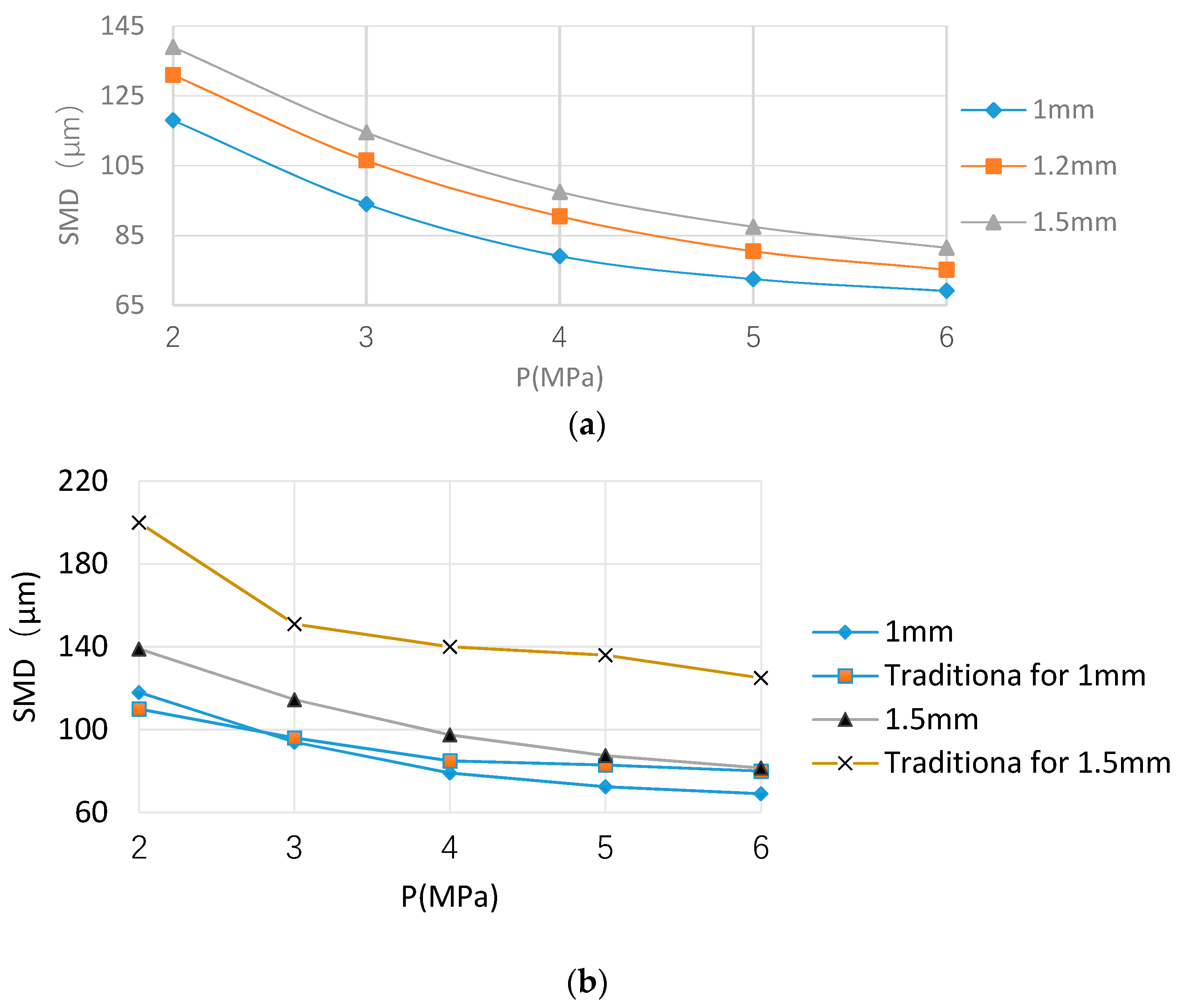
Figure 6a shows that the SMD curve is varied with spray pressure and nozzle diameter. When the spray pressure is less than 4 MPa, the droplets’ SMD decreases rapidly with the increase of spray pressure. When the spray pressure is above 5 MPa, the droplets’ SMD decrease slowly with the pressure. This indicates that the spray pressure has a significant effect on liquid atomization. As the kinetic energy of the droplets increases with the spray pressure, the higher kinetic energy is most likely to cause breakage of larger droplets into smaller ones. Figure 6 also shows that when the spray pressure reaches 5 MPa, even if the spray pressure continues to increase, fog particle SMD will not be reduced greatly. In other words, Figure 6a shows that at the same spray pressure, smaller nozzle aperture can produce smaller particle. Figure 6b shows the comparison between the nozzle and the traditional nozzles [40] in the SMD. The SMD of this swirl nozzle is smaller than the traditional nozzles for 1.5 mm and this swirl nozzle is smaller than the traditional nozzles for 1 mm when the spray pressure is above 3 MPa. According [4,5], better dust removal can be achieved using smaller diameter particles.
3.3. The Relationship between Atomization Angle and Spray Pressure and Nozzle Aperture
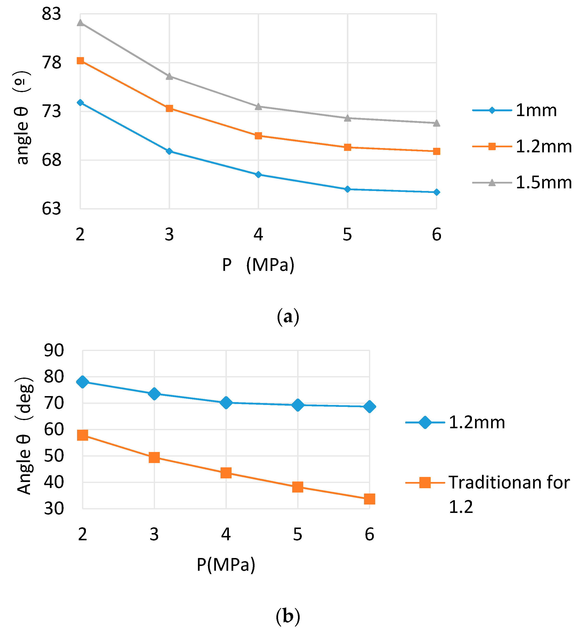
Figure 7a shows the relationship between the atomization angles and spray pressures for three nozzle apertures. It can be seen that the atomization angle reduces when the spray pressure increases from 2 to 4 MPa, and the atomization angle reduces slowly when the spray pressure is above 4 MPa, and even more slowly above 5 MPa. Although Figure 6 and Figure 7 share the similar trends, Figure 6 is caused by high-speed secondary breakup [41], and high speed aerodynamic force can lead to the droplets’ SMD decreasing rapidly when the pressure is less than 4 MPa and decreasing slowly above 5 MPa. Figure 7b shows the comparison between the nozzle and the traditional nozzles in the spray angle. For 1.2 mm diameter, as an example, the SMD of this swirl nozzle is smaller than that of the traditional nozzles from 2 MPa to 6 MPa. The decrease of atomization cone angle leads to the continuous reduction of the effective dust fall area of fog flow, which is not conducive to the capture of coal dust [4].
3.4. Axial and Radial Distributions of Particle SMD
Figure 8 shows the particle SMD in the central axis along the axial direction of fog flow spray in the fog field. It can be seen that with the increase of the axial distance from the nozzle, the fog particle SMD increases rapidly and the maximum diameter is about 10 cm from the nozzle, and then it decreases dramatically within the distance of 50 cm. After 100 cm, the curve gradually becomes level. This is because the density of fog particles is large at the near field of the nozzle, but the coupling process between the high velocities of particles and perturbation of aerodynamic force makes larger particles start a second atomization [42]. At the same time, the large distance and space is good for reducing particle collisions with each other to some degree. Both the particle collision and particle second atomization gradually reach equilibrium at about 50 cm away from the nozzle, so the curve beyond 100 cm is nearly horizontal.
Figure 9 shows the distribution of particle SMD in the radial direction in the spray field at different axial positions. It can be seen that the particle SMD is larger in the center of the fog than in the rim, and droplets diameter gradually decreases along the radial direction. Because a large number of fog particles exist near the nozzle, at this point, the outside air cannot be sucked into the internal fog field to mix fully with fog particles, which depresses the degree of fog particles breaking. Therefore, near of the nozzle, there are more concentrated fog particles and greater fog particle SMD. In contrast, a large amount of air is sucked into the fog field at further distances away from the axial line of the fog field, and many tiny particles produced by first and second breakup [30] are transported to the spray boundaries by the drag forces from the surrounding air and, therefore, the fog particles’ SMD are smaller than that of particles in the center field.
3.5. Speed Distribution of Fog Particles
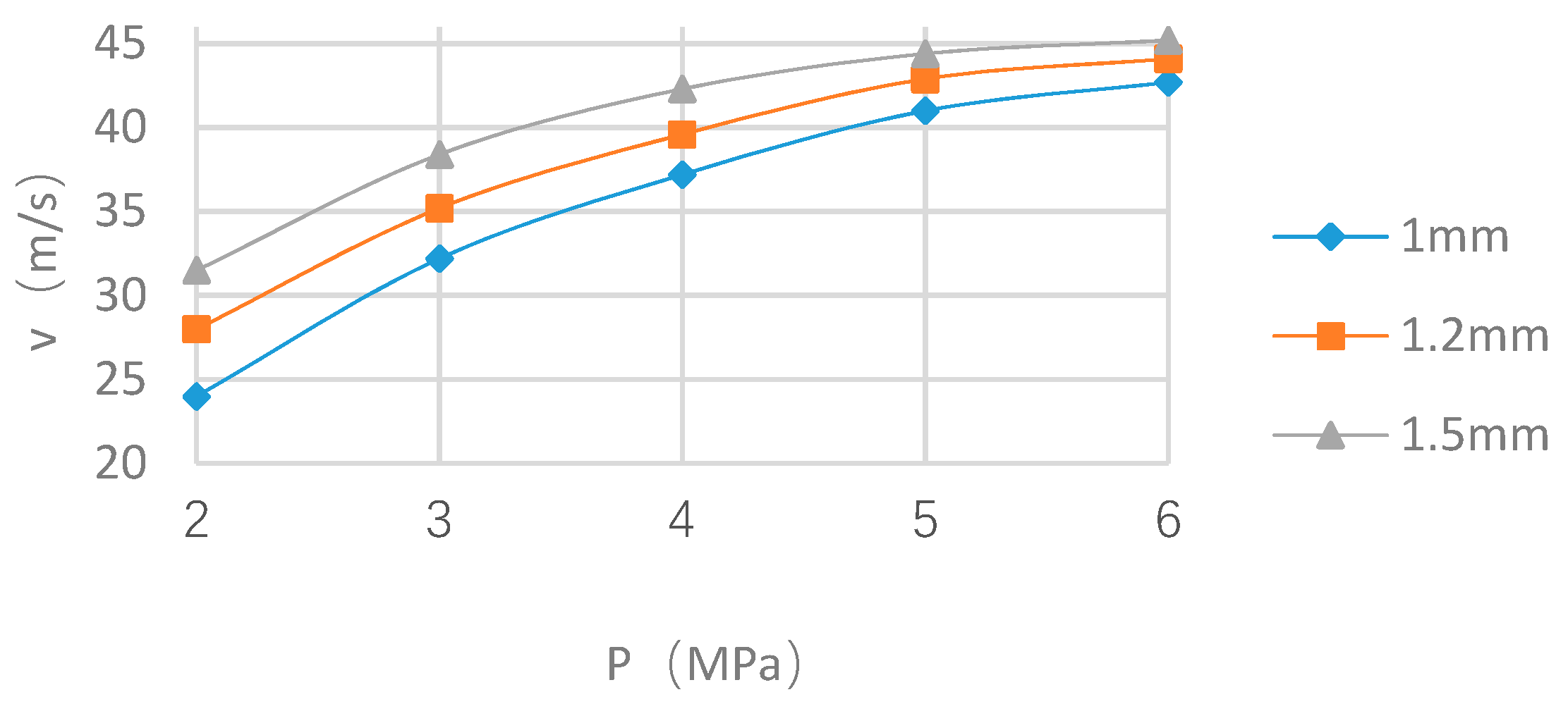
The velocities of droplets were investigated at different spray pressures and at different axial distances and are shown in Figure 10 and Figure 11, respectively. Figure 10 shows that at a point in the fog field, the speed of fog particles increases with the increase of spray pressure. For example, when the nozzle aperture is 1.2 mm, when spray pressure is increased from 2 to 3, 4, and 5 MPa, the speed of fog particles is increased from 28 m/s to 43 m/s. However, above 5 MPa, the growth rate of fog particle speed tends to be small. At the same time, Figure 10 also shows that the small nozzle aperture has smaller fog particle speed than that of the large nozzle aperture at the same spray pressure.
Figure 11 shows the relationship between the velocity of fog particles and the axial distance from center of the fog field. It indicates that the velocity of fog particles decreases gradually when the axial distance increases in the fog field at different spray pressure. For example, at 5 MPa, the axial speed is 50 m/s at 100 cm and then is reduced to 20 m/s at 300 cm. This is because when the nozzle’s high inner pressure sprays out the fog particles with high speed relative to the air speed, a large part of the kinetic energy of the fog particles is used to overcome air shearing and resistance. In this process, the larger diameter of fog particles is sheared and broken, the kinetic energy of the fog particles is further lost, so that the speed of fog particles reduces sharply. With the speed of fog particles decreasing, the shear effect of air on fog particles gradually reduces, the possibility of shear crushing and the loss of energy of fog particles are reduced and, therefore, the fog particle speed rate decreases gradually with the increase in axial distance.
4. Comparison of the Effects of the Nozzle in Practice
The swirl nozzle was used in a coal mine for spraying and dust settling as shown in Figure 12. It can be seen that the swirl nozzle sprays out tiny water droplets regularly. Inspectors in the coal mine had monitored coal dust concentration regularly, and they compared that with the results after the swirl nozzle was used; the data are listed in Table 1. The data in Table 1 are the average of five measurements. Table 1 shows that the swirl nozzle had very good application effects in dust settling, such as at the 1035 east tunnel of the coal mine where the dust concentration was 8.5 mg/m3 using a traditional nozzle, while after using the swirl nozzle, coal dust concentration was reduced to 6.51 mg/m3; the coal dust concentration was decreased by 23%.
5. Conclusions
The experimental and numerical studies about the mechanism and effectiveness of a swirl nozzle have been described for dust control and the nozzle was successfully used in underground coal mines. Further investigations may be performed on the interactions between traditional nozzle structure and this swirl nozzle structure in the chamber, and eddy simulations could be conducted. However, the current study can provide the following conclusions:
- (1)
- For this swirl nozzle, when the spray pressure is low, the particles’ SMD decreases rapidly with the increase of the spray pressure. When the pressure reaches 5 MPa, the particles’ SMD decreases slowly; even if the spray pressure continues to increase, the particles’ SMD reduces very slowly. According to this character, a normal pressure pump can be used in practice instead of an expensive high-pressure pump for cost reduction.
- (2)
- Along the axial distance from the nozzle, the fog particles’ SMD increase rapidly and then decrease rapidly; after 100 cm, it gradually becomes stable. The processes of increase and decrease are relatively short. The particles’ SMD was the largest in the center of the fog field and decreases gradually along the radial direction.
- (3)
- The axial speed of particles increases with the increase of spray pressure, however, the increase rate tends to be slow when the pressure is above 5 MPa. The speed of particles decreases with the increase of aperture under the same spray pressure. The speed of the fog particles decreases gradually with the increase of axial distance in the fog field, and the rate of decrease gradually slows down.
- (4)
- Increasing of spray pressure and decreasing of nozzle aperture will make the fog particles’ size distribution more concentrated and uniform. The fog particles’ size distribution is also more uniform where it is further away from the nozzle axially and radially.
Author Contributions
G.G., C.W. and Z.K. conceived the whole procedure of this study; G.G. performed, analyzed the mechanical tests and wrote writing-original draft preparation; G.G. and C.W. made revisions of the manuscript; Z.K. carried out project management and investigation.
Funding
This research was funded by the Joint Funds of the National Natural Science Foundation of China (No. U1261107) and the Fundamental Research Funds of the Natural Science of Shanxi Province (No. 2012011018-1).
Conflicts of Interest
The authors declare no conflict of interest.
Nomenclature
| dpmin | dust particle diameter (m) |
| Δs | distribution of fog particle size |
| U | dynamic viscosity |
| Stk | stokes number |
| ρp | dust density |
| v0 | air flow rate |
| D | nozzle diameter (m) |
| Dw | droplet diameter |
| Q | nozzle flowrate (m3/s) |
| Pw | pressure of water (MPa) |
| k | test coefficient (k = 1.34) |
| v | water jet speed (m/s) |
| dSMD | Sauter mean diameter |
| di | the droplet diameter |
| ni | number of ith segment |
| m | the number of droplet diameter segments |
Abbreviations
| SMD | Sauter mean diameter |
| PIV | Particle image velocimetry |
| PDA | Phase-doppler anemometry |
| CFD | Computational fluid dynamics |
| LDA | Laser doppler anemometry |
References
- Russell, R. Coal dust control. Power Eng. 2013, 117, 28–30. [Google Scholar]
- Li, Y.Q.; Qin, Y.P.; Yang, X.B. New progress on coal mine dust in recent ten years. Procedia Eng. 2011, 26, 738–743. [Google Scholar]
- Wang, J.; Gao, Y. Development of coal mine downhole high-pressure dust reduction and water supply system monitor device. In Proceedings of the 2011 International Conference on Electronics, Communications and Control (ICECC), Ningbo, China, 9–11 September 2011; pp. 2032–2034. [Google Scholar]
- Wang, P.-F.; Liu, R.-H.; Tang, M.; Zhang, W.; Gui, Z. Experimental study on atomization characteristics and dust suppression efficiency of high-pressure spray in underground coal mine. J. Chin. Coal Soc. 2015, 40, 2124–2130. [Google Scholar]
- Pang, J.; Xie, J.; Li, C.; Hao, Y.; Jian, J. Study on dust distribution features of high cutting fully-mechanized coal mining face. Coal Sci. Technol. 2017, 45, 78–83. [Google Scholar]
- Liu, Q.; Kou, Z.; Gao, G.; Hou, T. Experimental research on the comprehensive operating parameters of atomized dust collector. Exp. Therm. Fluid Sci. 2015, 62, 216–221. [Google Scholar] [CrossRef]
- Kudo, T.; Sekiguchi, K.; Sankoda, K.; Namiki, N.; Nii, S. Effect of ultrasonic frequency on size distributions of nano sized mist generated by ultrasonic atomization. Ultrason. Sonochem. 2017, 37, 16–22. [Google Scholar] [CrossRef] [PubMed]
- Chang, P.; Bai, B. An improved method of gas well deliquification using supersonic nozzle. Int. J. Heat Mass Transf. 2017, 108, 2262–2272. [Google Scholar] [CrossRef]
- Wu, D.; Yin, K.; Yin, Q.; Zhang, X.; Cheng, J.; Ge, D.; Zhang, P. Reverse circulation drilling method based on a supersonic nozzle for dust control. Appl. Sci. 2016, 7, 5. [Google Scholar] [CrossRef]
- Charinpanitkul, T.; Tanthapanichakoon, W. Deterministic model of open-space dust removal system using water spray nozzle: Effects of polydispersity of water droplet and dust particle. Sep. Purif. Technol. 2011, 77, 382–388. [Google Scholar] [CrossRef]
- Pollock, D.; Organiscak, J. Airborne dust capture and induced airflow of various spray nozzle designs. Aerosol Sci. Technol. 2007, 41, 711–720. [Google Scholar] [CrossRef]
- Ren, G.; Heo, S.; Kim, T.-H.; Cheong, C. Response surface method-based optimization of the shroud of an axial cooling fan for high performance and low noise. J. Mech. Sci. Technol. 2013, 27, 33–42. [Google Scholar] [CrossRef]
- Liu, J.; Yu, Q.; Guo, Q. Experimental investigation of liquid disintegration by rotary cups. Chem. Eng. Sci. 2012, 73, 44–50. [Google Scholar] [CrossRef]
- Bizjan, B.; Širok, B.; Hočevar, M.; Orbanić, A. Ligament-type liquid disintegration by spinning wheel. Chem. Eng. Sci. 2014, 116, 172–182. [Google Scholar] [CrossRef]
- Kamiya, T.; Kayano, A. Film-type disintegration by rotating disk. J. Chem. Eng. Jpn. 1972, 5, 174–182. [Google Scholar] [CrossRef]
- Liu, X.; Gao, G. Atomization characteristics of ultrasonic nozzle with hartmann whistle structure. Chin. J. Vac. Sci. Technol. 2016, 36, 268–272. [Google Scholar]
- Wilson, J.; Grib, S.; Darwish Ahmad, A.; Renfro, M.; Adams, S.; Salaimeh, A. Study of near-cup droplet breakup of an automotive electrostatic rotary bell (esrb) atomizer using high-speed shadowgraph imaging. Coatings 2016, 8, 174. [Google Scholar] [CrossRef]
- Ebrahimi, A.; Langrish, T.A.G. Spray drying and crystallization of lactose with humid air in a straight-through system. Drying Technol. 2016, 33, 808–816. [Google Scholar] [CrossRef]
- Koschel, D.; Stark, W.; Karmann, F.; Sennekamp, J.; Müller-Wening, D. Extrinsic allergic alveolitis caused by misting fountains. Respir. Med. 2005, 99, 943–947. [Google Scholar] [CrossRef] [PubMed]
- Avvaru, B.; Patil, M.N.; Gogate, P.R.; Pandit, A.B. Ultrasonic atomization: effect of liquid phase properties. Ultrasonics 2006, 44, 146–158. [Google Scholar] [CrossRef] [PubMed]
- Barreras, F.; Amaveda, H.; Lozano, A. Transient high-frequency ultrasonic water atomization. Exp. Fluids 2002, 33, 405–413. [Google Scholar] [CrossRef]
- Yang, Y.; Wen, C. CFD modeling of particle behavior in supersonic flows with strong swirls for gas separation. Sep. Purif. Technol. 2017, 174, 22–28. [Google Scholar] [CrossRef]
- Wen, C.; Yang, Y.; Walther, J.H.; Pang, K.M.; Feng, Y. Effects of delta wing on the particle flow in a gas supersonic separator. Powder Technol. 2016, 304, 261–267. [Google Scholar] [CrossRef]
- Wen, C.; Li, A.; Walther, J.H.; Yang, Y. Effect of swirling device on flow behavior in a supersonic separator for natural gas dehydration. Sep. Purif. Technol. 2016, 115, 1357–1362. [Google Scholar] [CrossRef] [Green Version]
- Wen, C.; Cao, X.; Yang, Y.; Zhang, J. Evaluation of natural gas dehydration in supersonic swirling separators applying the discrete particle method. Adv. Powder Technol. 2012, 23, 228–233. [Google Scholar] [CrossRef]
- Yang, Y.; Li, A.; Wen, C. Optimization of static vanes in a supersonic separator for gas purification. Fuel Process. Technol. 2017, 156, 265–270. [Google Scholar] [CrossRef]
- Benajes, J.; Pastor, J.V.; Payri, R.; Plazas, A.H. Analysis of the influence of diesel nozzle geometry in the injection rate characteristics. J. Fluids Eng. 2004, 126, 63–71. [Google Scholar] [CrossRef]
- Payri, R.; Salvador, F.J.; Gimeno, J.; Zapata, L.D. Diesel nozzle geometry influence on spray liquid-phase fuel penetration in evaporative conditions. Fuel 2008, 87, 1165–1176. [Google Scholar] [CrossRef]
- Hadef, R.; Lenze, B. Measurements of droplets characteristics in a swirl-stabilized spray flame. Exp. Therm. Fluid Sci. 2005, 30, 117–130. [Google Scholar] [CrossRef]
- Husted, B.P.; Petersson, P.; Lund, I.; Holmstedt, G. Comparison of PIV and PDA droplet velocity measurement techniques on two high-pressure water mist nozzles. Fire Saf. J. 2009, 44, 1030–1045. [Google Scholar] [CrossRef]
- Rashad, M.; Yong, H.; Zheng, Z. Effect of geometric parameters on spray characteristics of pressure swirl atomizers. Int. J. Hydrogen Energy 2016, 41, 15790–15799. [Google Scholar] [CrossRef]
- Soltani, M.R.; Ghorbanian, K.; Ashjaee, M.; Morad, M.R. Spray characteristics of a liquid–liquid coaxial swirl atomizer at different mass flow rates. Aerosp. Sci. Technol. 2005, 9, 592–604. [Google Scholar] [CrossRef]
- Jiang, Z.; Wang, M.; Chen, J.; Lin, M. Atomization characteristics and dust suppression mechanism of a gas water nozzle. J. Harbin Inst. Technol. 2017, 49, 151–157. [Google Scholar]
- Cheng, W.-M.; Nie, W.; Zhou, G.; Zuo, Q.-M. Study of dust suppression by atomized water from high-pressure sprays in mines. J. China Univ. Min. Technol. 2011, 40, 185–190. [Google Scholar]
- Fletcher, D.F.; Guo, B.; Harvie, D.J.E.; Langrish, T.A.G.; Nijdam, J.; Williams, J. What is important in the simulation of spray dryer performance and how do current CFD models perform. Appl. Math. Model. 2006, 30, 1281–1292. [Google Scholar] [CrossRef]
- Launder, B.E.; Sharma, B.I. Application of the energy dissipation model of turbulence to the calculation of flow near a spinning disc. Lett. Heat Mass Transf. 1974, 1, 131–138. [Google Scholar] [CrossRef]
- Wu, L.; Wang, Z.-G.; Li, Q.; Zhang, J. Investigations on the droplet distributions in the atomization of kerosene jets in supersonic crossflows. Appl. Phys. Lett. 2015, 107, 104103. [Google Scholar] [CrossRef]
- Kowalczuk, P.B.; Drzymala, J. Physical meaning of the Sauter mean diameter of spherical particulate matter. Part. Sci. Technol. 2016, 34, 645–647. [Google Scholar] [CrossRef]
- Zhou, Y. An Investigation of Droplet Behavior during Spray-Based Manufacturing Processes. Ph.D. Thesis, University of California, Irvine, CA, USA, 1999. [Google Scholar]
- Cheng, W.-M.; Zhou, G.; Zuo, Q.-M.; Nie, W.; Wang, G. Experimental research on the relationship between nozzle spray pressure and atomization particle size. J. China Univ. Min. Technol. 2010, 35, 1308–1313. [Google Scholar]
- Faeth, G.M.; Hsiang, L.-P.; Wu, P.-K. Structure and breakup properties of sprays. Int. J. Multiphase Flow 1995, 21, 99–127. [Google Scholar] [CrossRef]
- Yi, Y. Numerical Modeling of Spray Primary Breakup with Application to Diesel Engines. Ph.D. Thesis, University of Wisconsin-Madison, Madison, WI, USA, 2002. [Google Scholar]
Figure 1.
Tangential injection swirl nozzle (A is cross section symbols for location).

Figure 2.
Measurement setup with swirl nozzle and Laser Doppler Anemometry. (1: receiver, 2: swirl nozzle, 3: transmitter, 4: pressure gauge, 5: high pressure pump unit, 6: flow meter, 7: valve, 8: tank, 9: high-speed camera, 10: computer).
Figure 2.
Measurement setup with swirl nozzle and Laser Doppler Anemometry. (1: receiver, 2: swirl nozzle, 3: transmitter, 4: pressure gauge, 5: high pressure pump unit, 6: flow meter, 7: valve, 8: tank, 9: high-speed camera, 10: computer).

Figure 3.
Setup and testing of the swirl nozzle.

Figure 4.
Coordinate system was established in the spray area. H = horizontal axis and L = vertical axis.
Figure 4.
Coordinate system was established in the spray area. H = horizontal axis and L = vertical axis.

Figure 5.
Results of numerical simulations of two types of nozzles: (a) the swirl nozzle mass flow path line, (b) the traditional nozzle mass flow path line, (c) the X-velocity on the swirl nozzle outlet face, and (d) the X-velocity on the traditional nozzle outlet face.
Figure 5.
Results of numerical simulations of two types of nozzles: (a) the swirl nozzle mass flow path line, (b) the traditional nozzle mass flow path line, (c) the X-velocity on the swirl nozzle outlet face, and (d) the X-velocity on the traditional nozzle outlet face.


Figure 6.
Size of droplets (Sauter Mean Diameter, SMD) in different spray pressures (P) and nozzle diameters. (a) SMD and spray pressures for three nozzle apertures. (b) The comparison between the nozzle and the traditional nozzles in the SMD.
Figure 6.
Size of droplets (Sauter Mean Diameter, SMD) in different spray pressures (P) and nozzle diameters. (a) SMD and spray pressures for three nozzle apertures. (b) The comparison between the nozzle and the traditional nozzles in the SMD.

Figure 7.
Atomization angle in different spray pressures. (a) Atomization angles and spray pressures for three nozzle apertures. (b) The comparison between the nozzle and the traditional nozzles in the spray angle.
Figure 7.
Atomization angle in different spray pressures. (a) Atomization angles and spray pressures for three nozzle apertures. (b) The comparison between the nozzle and the traditional nozzles in the spray angle.

Figure 8.
The axial distribution of droplet diameter. (a) The axial distribution of droplet diameter over 300 cm. (b) The axial distribution within 30 cm.
Figure 8.
The axial distribution of droplet diameter. (a) The axial distribution of droplet diameter over 300 cm. (b) The axial distribution within 30 cm.

Figure 9.
The radial distribution of droplets’ diameter.

Figure 10.
Droplet velocity in different spray pressures.

Figure 11.
The axial distribution of droplet velocity.

Figure 12.
Swirl nozzle being used in a coal mine.


Table 1.
Swirl nozzle spray dust effect in coal mine.
| Location | Traditional Nozzle | Swirl Nozzle | Reduction |
|---|---|---|---|
| 1035 East tunnel | 8.5 mg/m3 | 6.51 mg/m3 | 23% |
| Belt tunnel | 13 mg/m3 | 11 mg/m3 | 15% |
© 2018 by the authors. Licensee MDPI, Basel, Switzerland. This article is an open access article distributed under the terms and conditions of the Creative Commons Attribution (CC BY) license (http://creativecommons.org/licenses/by/4.0/).
Share and Cite
MDPI and ACS Style
Gao, G.; Wang, C.; Kou, Z. Experimental Studies on the Spraying Pattern of a Swirl Nozzle for Coal Dust Control. Appl. Sci. 2018, 8, 1770. https://doi.org/10.3390/app8101770
AMA Style
Gao G, Wang C, Kou Z. Experimental Studies on the Spraying Pattern of a Swirl Nozzle for Coal Dust Control. Applied Sciences. 2018; 8(10):1770. https://doi.org/10.3390/app8101770
Chicago/Turabian StyleGao, Guijun, Changjiang Wang, and Ziming Kou. 2018. "Experimental Studies on the Spraying Pattern of a Swirl Nozzle for Coal Dust Control" Applied Sciences 8, no. 10: 1770. https://doi.org/10.3390/app8101770
Note that from the first issue of 2016, this journal uses article numbers instead of page numbers. See further details here.