1. Introduction
Railway bogies sit beneath railway cars and support the train’s load while enabling acceleration and deceleration. The bogie frame is connected to electrical and mechanical equipment, including the transmission system, braking equipment, suspension equipment, and wheel set. The bogie controls the train speed and the passage rate at a curve, and influences the running stability. Bogie frames are generally comprised of metallic materials, including SM490A steel or high strength steel [
1]. However, recently, fiber-reinforced composites have been used to reduce the structural weight of the bogie [
2,
3,
4,
5,
6]. This decreased weight reduces the amount of energy that is required to run the vehicle. In addition, the maintenance costs of the rail tracks are reduced, owing to the reduced axle load. Fiber-reinforced composites have a higher specific strength and specific stiffness than metallic materials. Their durability and resistance to corrosion are also excellent. However, their design and production requires advanced technology, owing to the non-uniformity of the material, and the breakage mode complexity. Composite bogie frames are designed to have a complex internal structure, and all of the fabrication processes are performed manually and in sequence by workers. Hence, even if they are fabricated via qualified standard fabrication processes, there is a high probability that they will not have a uniform structural performance. Thus, there is a need for technology that can effectively monitor whether or not the composite structure meets the required performance design. Currently, based on finite element (FE) analysis results, only specific positions where deformation is expected are monitored, using a strain gauge during the load test. An optical fiber sensor has several merits, such as a small diameter (250 μm), the ability to represent multi-point measurements as one line, and immunity from electromagnetic interference because there is no flow of free electrons. Recently, a fiber Bragg grating (FBG) sensor, a type of optical fiber sensor, has been studied broadly as a replacement for the strain gauge. Similar to the strain gauge, it can only be used in predetermined positions [
7,
8,
9], but it also has a limited capacity to monitor the distributed strain of a structure.
A method for monitoring structural deformation in composite bogie frames was developed for the first time using an optical fiber sensor system with a high spatial resolution based on Brillouin optical correlation domain analysis (BOCDA). In the vertical train load test, the distributed strain of the lower part of the composite side beam was measured using an attached 3 m-long optical fiber with a 3 cm spatial resolution. The result was compared with the FE analysis results to verify the design. In addition, an optical fiber was embedded inside the frame of the bogie during the fabrication process in order to monitor the frame’s strain distribution during vertical train load tests. The strain distribution monitoring results can be used to verify the balance of the bogie, and to detect unpredictable concentrated loads due to internal defects produced during the production process.
2. A Distributed Optical Fiber Sensor System Based on BOCDA
Figure 1 shows the BOCDA system. The continuous wave (CW) light from the laser diode (LD) is divided by a 50/50 coupler into the pump and probe arms. The pump wave is chopped by an electro-optic modulator (EOM) for lock-in detection, and it is launched to a sensing optical fiber after being amplified by an Er-doped fiber amplifier (EDFA). The probe wave is generated by a single-side band modulator (SSBM) and a microwave synthesizer, where the frequency offset between the pump and probe waves is swept near the Brillouin frequency of the sensing optical fiber within a 1 GHz span. The probe wave is amplified by another EDFA, and then it is propagated along the sensing optical fiber in the opposite direction to the pump wave. A sinusoidal frequency modulation is applied to the LD by a LD current modulator to create a correlation peak (CP), the sensing position, within the sensing optical fiber. The probe wave with Brillouin gain is detected by a photo detector (PD), and the BOCDA signal is acquired by a data acquisition board (DAQ) after being processed by a lock-in amplifier. The frequency of the LD current modulation is adjusted to change the measurement position along the sensing optical fiber, while the spatial resolution, which is determined by the modulation parameters of the LD [
10,
11], is set to 3 cm for all measurements. After the Brillouin frequency shift, which is the change in the central frequency of the Brillouin gain spectrum determined for each position by embedded software, local strain is calculated by applying a pre-acquired coefficient of 20 με/MHz.
The BOCDA system is packaged in a single portable box for easy handling and access to the sensing optical fiber. The optical fibers of the pump and probe arms protrude from the system box, and are spliced to the sensing optical fiber to minimize the reflection from connecting points for noise suppression.
3. Fabrication of the Composite Bogie Frame
A railcar’s bogie is located between the car body and the rails; it is the part that enables the car body to move on top of the rails. It is composed of a bogie frame, wheels, axles, suspension, and a brake system. As shown in
Figure 2, it has an H-shaped structure, with two side beams that are connected to the axles, which support the load of the car and passengers, as well as two crossbeams that are attached to the brake system, which handle the bogie frame’s torsional load [
12].
For this study, a glass fiber-reinforced plastic (GFRP) material was used to build the composite bogie frame. The side beams and crossbeams were built first, and then assembled. The exterior was covered with a composite skin to complete the bogie frame.
3.1. Fabrication of the Internal Structure of Composite Bogie Frame
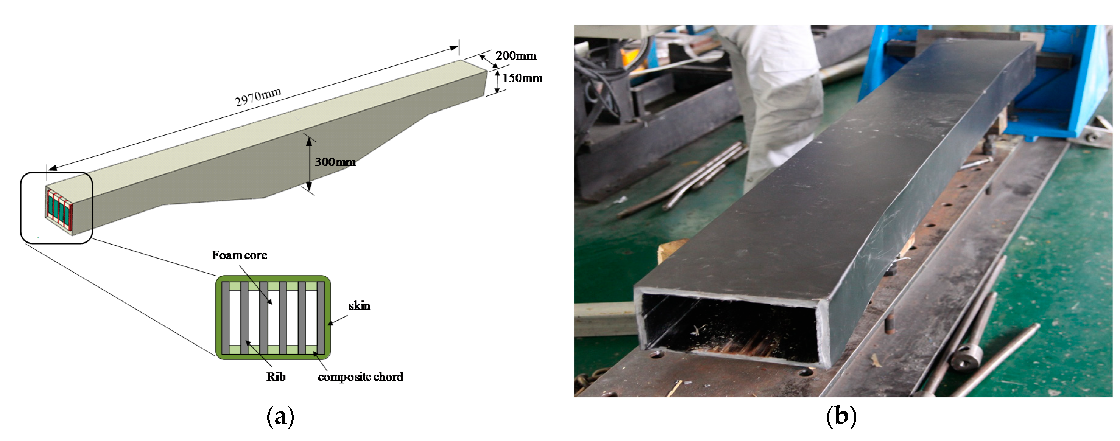
The composite side beam was designed such that its shape and internal structure can support the load of the railcar and passengers while simultaneously reducing its own weight. As shown in
Figure 3a, the internal structure was composed of ribs, a foam core, and composite chords, which were covered by a skin.
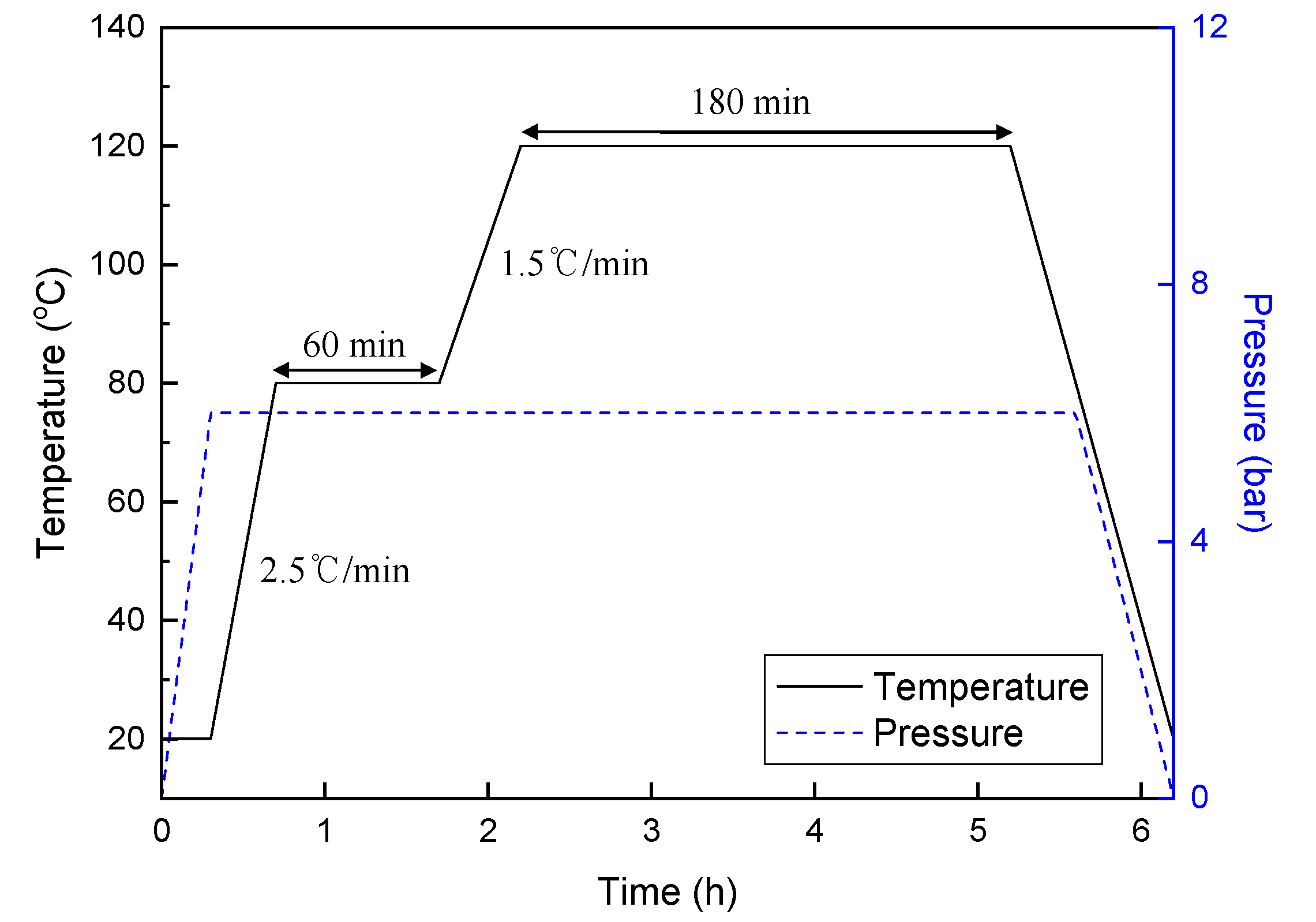
The ribs were built beforehand using a resin infusion method with a mixture of quadriaxial glass fiber fabric and epoxy resin. The ribs were attached to foam cores using FM73 adhesive film. The composite chords located above and below the foam core were created from 72 layers of 4-harness satin fabric glass/epoxy pre-pregs, which were stacked on top of each other. This internal structure was subjected to a 6 h-long forming process in an autoclave [
13]. After the process was completed, 56 layers of GEP224 pre-pregs were stacked on top of the structure to form the skin. After this, another 6 h-long forming process in the autoclave was performed to finally complete the formation of the composite side beams. The finally formed composite side beam was 2970 mm long and 200 mm wide. Its height gradually increased from 150 mm at each end, to 300 mm in the middle of the beam. To fabricate the composite crossbeam, 55 layers of GEP224 pre-pregs were stacked in a square mold, and a 6 h-long forming process in the autoclave was performed. As shown in
Figure 3b, the composite crossbeam is similar to a hollow rectangle.
3.2. Fabrication of Composite Bogie Frame and Embedding of Optical Fiber
The two side beams and the crossbeams were joined in an H shape using a fixing jig. An adhesive film was attached to the bottom of the structure so that the optical fiber could be attached to it. A standard single mode optical fiber (Samsung, Seoul, Korea) with a diameter of 250 μm was attached to the adhesive film from one side beam, across the crossbeam, and to the other side beam. It is noteworthy that the coating material of fiber was acrylate, to which the maximum applicable strain was about 5000 με. Although the limit was sufficient for this work, we believe that optical fibers coated with a commercially available special polymer (e.g., polyimide), would be better suited for applications requiring measurement of larger strains. The optical fiber was placed in the middle of the beam at the location shown in
Figure 4a, and 60 mm heat-shrink tubing with an internal steel core was used to protect it from being cut at the ends of the composite side beam, as shown in
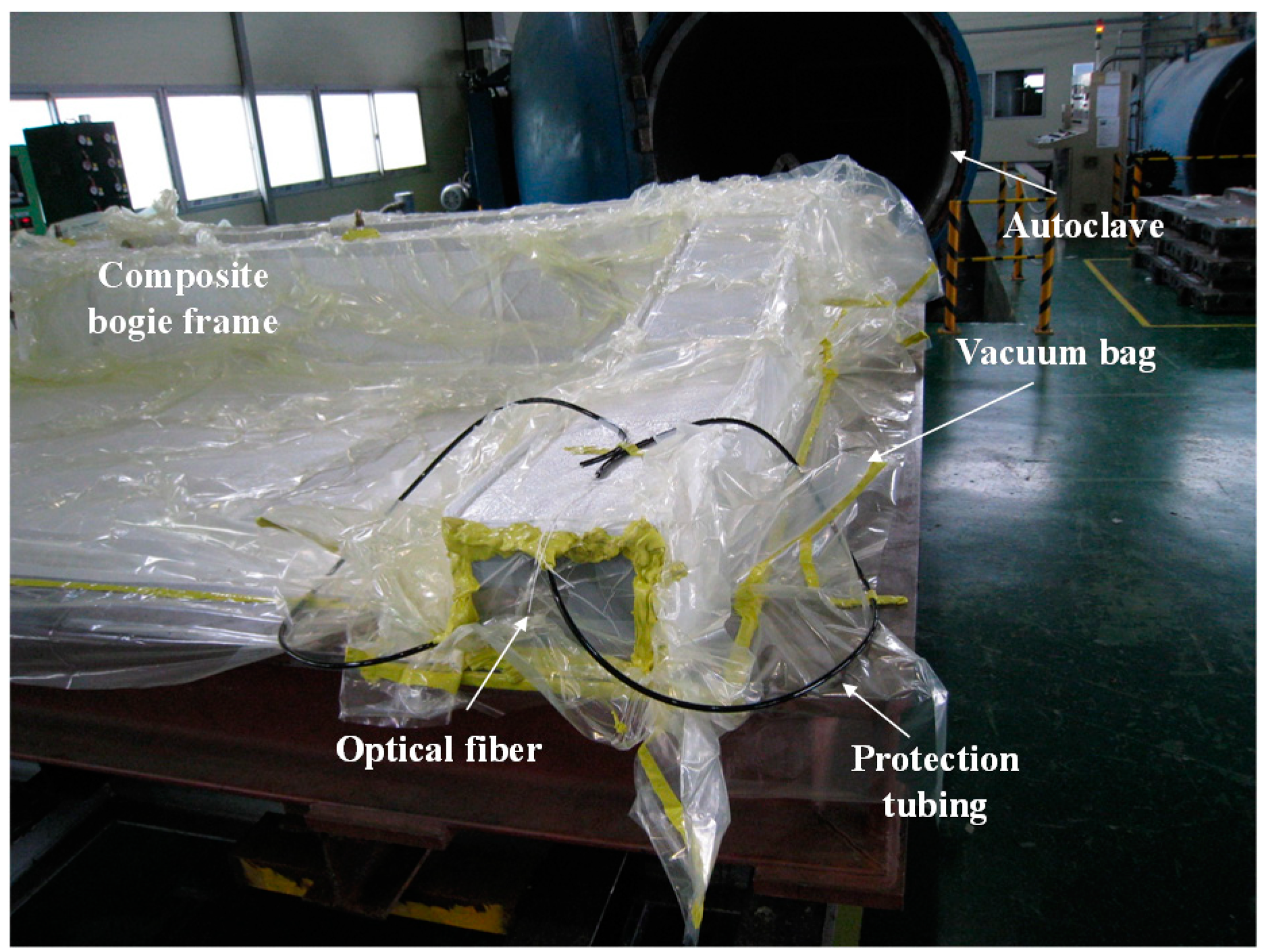
Figure 4b. Fifteen layers of GEP224 pre-pregs were stacked on top of the optical fiber to complete the skin. The stacked composite bogie frame was placed on a steel table for autoclave molding, and the exterior was sealed with a vacuum bag shown in
Figure 5. The embedded optical fiber was protected inside the PVC protection tubing and allowed to pass through the vacuum bag to the outside. After this, the thermal cycle shown in
Figure 6 was used for the 6 h forming process in the autoclave to complete the composite bogie frame.
4. Distributed Strain Monitoring Using the BOCDA System
4.1. Distributed Strain Monitoring of the Composite Side Beam
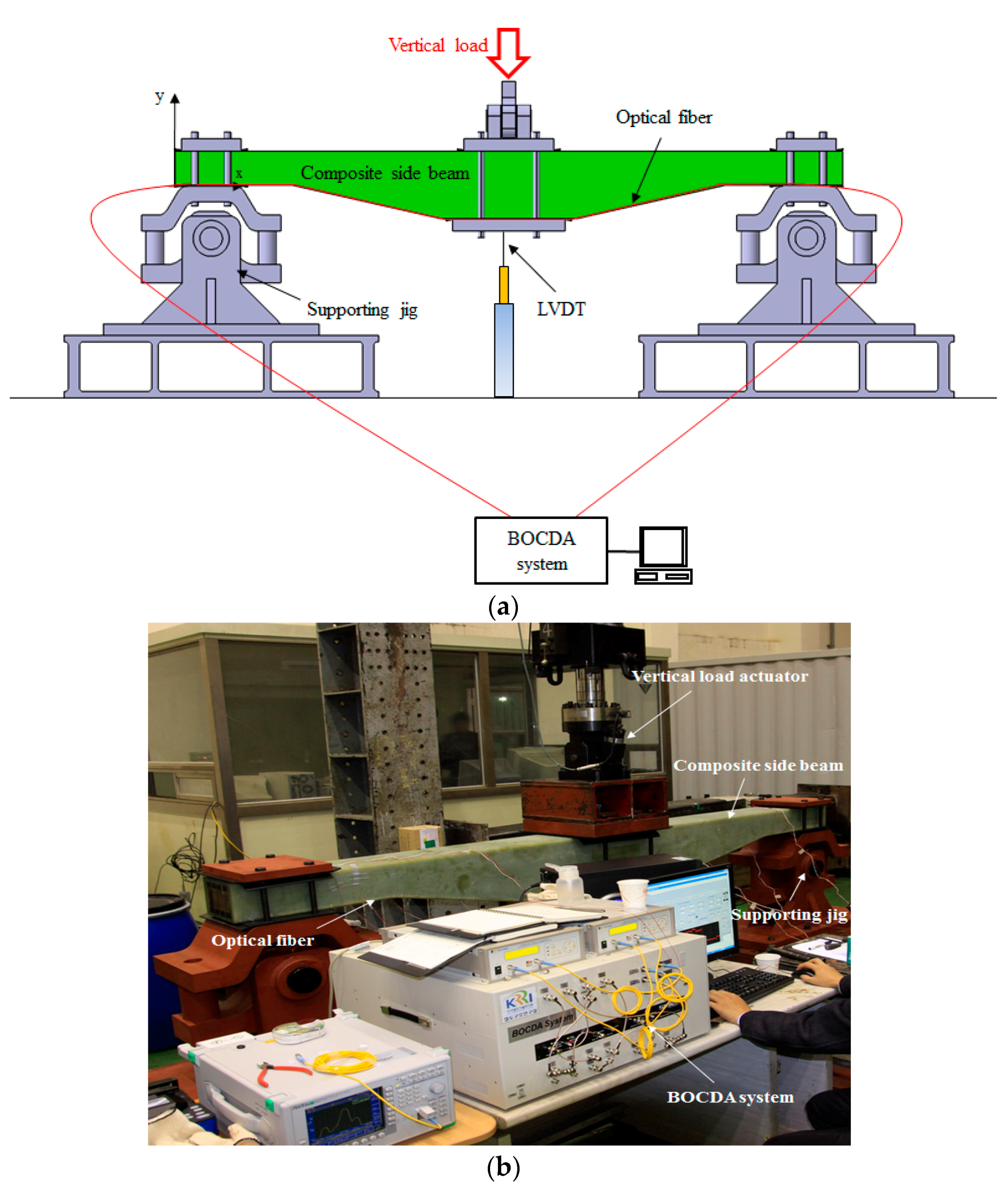
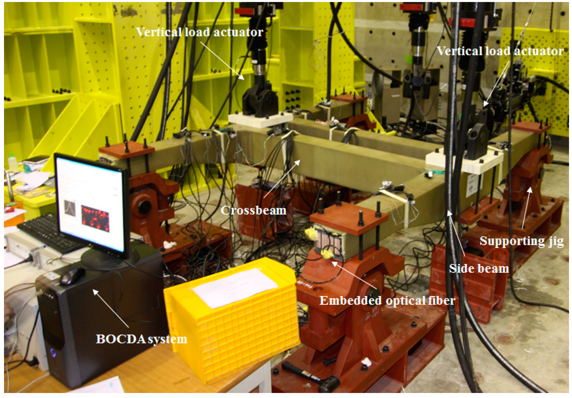
Figure 7 shows the experimental setup for strain monitoring. Both ends of the composite side beam were fixed on supporting jigs, and a vertical load actuator (MTS, Eden Prairie, MS, USA) was placed in the middle, 1.485 m from the ends of the side beam. In the longitudinal direction, a single mode optical fiber with a diameter of 250 μm and a length of 2.97 m was attached to the lower part of the composite side beam using Araldite epoxy (Huntsman, Woodlands, TX, USA). The attached optical fiber was connected to the developed BOCDA system. A linear variable differential transformer (LVDT) was attached to the bottom of the side beam to measure the center deflection of the side beam.
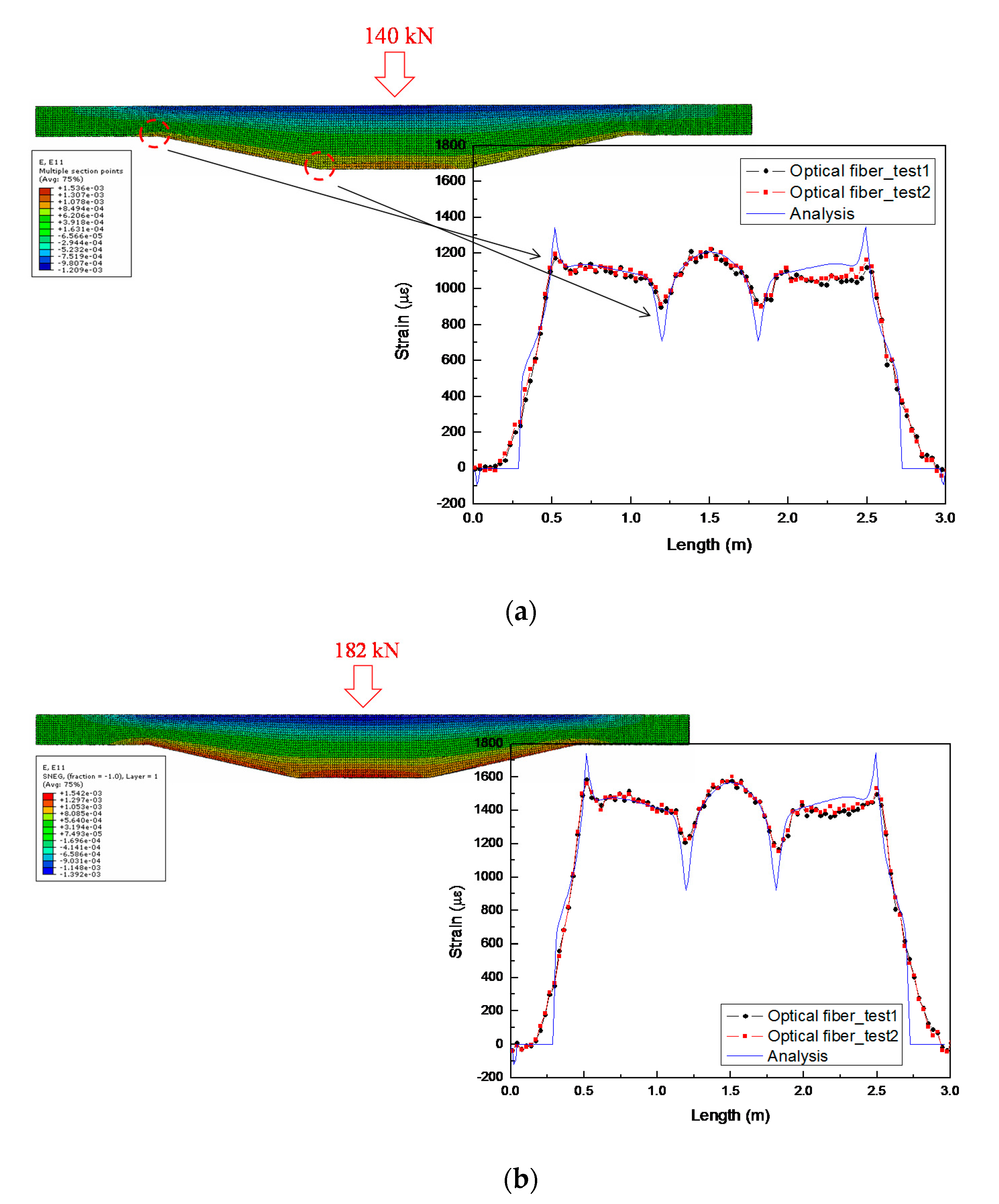
The composite side beam’s performance was determined by using a vertical load actuator to apply a 140 kN static load, which is a design requirement for urban subway trains, and a 182 kN dynamic load to consider the dynamic effect that occurs while the railcar is being operated. The test was performed twice to confirm the reproducibility of the results. The objective of the experiment was to monitor the strain distribution of the composite side beam using the developed BOCDA system when a vertical train load was applied, and to compare it with FE analysis results to confirm that the composite side beam was fabricated as designed. The strain distribution of the optical fiber attached to the composite side beam is shown in
Figure 8. The experimental data for the optical fiber were compared to the computational FE analysis results to validate the distributed sensing data. The composite side beam was computationally modeled, and the structural behavior was analyzed using the finite element method [
14].
The strain was measured at 3 cm intervals using the optical fiber. The overall strain distributions for both cases agree well with the analysis results. The composite side beam has a symmetrical structure; hence, the strain is also symmetrically distributed around the middle. The optical fiber sensor measurements obtained on the right side of the composite side beam were at most 70 με less than the FE analysis results, reflecting a stiffness mismatch caused by non-uniform thickness that developed during the fabrication process. The measured strain with the optical fiber sensor did not agree well with the FE analysis results at the bend, where the structure’s shape changes drastically, as shown in
Figure 8a. In these inflection sections, there was a mismatch between the design and the fabricated product; hence, precise values could not be obtained via FE analysis. However, an accurate value of the strain was obtained using the optical fiber. The maximum strain occurred in the middle of the composite side beam; when the vertical train load was 182 kN, the strain was 1602 με, ~1.3 times higher than that when the load was 140 kN (1222 με). There was good agreement between the results obtained using the optical fiber when the measurements were repeated for the second time, confirming the sensor’s reproducibility and reliability.
4.2. Distributed Strain Monitoring of the Composite Bogie Using an Embedded Optical Fiber
As shown in
Figure 9, the side beams on both sides of the composite bogie frame were fixed using four supporting jigs; two vertical load actuators were placed above the composite side beams on both sides. The location and amount of the load applied to the composite side beams were the same as in the vertical train load tests. The optical fiber embedded in the composite bogie frame was connected to the BOCDA system to measure the strain distribution in the composite bogie frame during the vertical train load test.
Figure 10 shows the strain distribution results obtained using the embedded optical fiber. The strain at the left and right composite side beams had positive values when a vertical train load was applied to the composite bogie frame; however, the crossbeam was not deformed because the crossbeam is a torsion-resisting structure in the composite bogie frame, and is unaffected by the vertical train load. The maximum strain occurred at the intersection of the side beam and crossbeam, and the distribution of strain changed sharply according to the shape of the composite bogie frame. The left and right composite side beams had the same strain distributions. This symmetry shows that they were well fabricated. The point at which the left composite side beam is attached to the crossbeam showed more drastic changes in strain than the same part on the right-hand side. The maximum strain in the left joint was 1.3 times higher than that in the right joint.
The Brillouin gain spectrum in
Figure 11 shows a side peak at this joint. This shows that the strain distribution within the short section (i.e., a spatial resolution of 3 cm) was not uniform, and that an abrupt strain change occurred on the optical fiber at this joint [
15,
16]. This means that a fabrication mismatch occurred during the assembly of the composite bogie frame, and hence, structurally weak areas were present. Therefore, concentrated monitoring would be needed for this joint during actual operation. The maximum strain in the composite bogie frame during the 182-kN vertical train load test was an allowable value, and no residual deformation occurred after the test, confirming that the bogie frame was structurally stable.
The embedded optical fiber could also be used to measure changes in maximum strain and strain distribution in real time in subsequent tests; thus, allowing for the detection of internal cracks.
5. Conclusions
An optical fiber sensor system with a high spatial resolution based on BOCDA was developed to monitor the structural deformation of composite bogie frames. The optical fiber was attached along the length of the lower part of the fabricated composite side beam to measure the distribution of strain in all sections during a vertical load test. The results obtained using the optical fiber were in good agreement with the results of the FE analysis, but there were sections where stiffness mismatches occurred, owing to the non-uniformity in thickness, which was the result of the fabrication process. An optical fiber was embedded in the composite bogie frame during the fabrication process, and it was used to measure the strain distribution in all sections during the vertical load test. The left and right side beams had the same strain distribution, indicating that the composite bogie frame was well balanced. Their structural stability was confirmed from this experiment. However, unpredictable strain occurred where the left side beam met the crossbeam, as confirmed by the side peak in the Brillouin spectrum for this section. This was attributed to a fabrication mismatch during the assembly of the composite bogie frame. The maximum strain was less than the limit, and residual deformation did not occur, ensuring the structural stability of the composite bogie frame. The occurrence of internal flaws in the composite bogie frame cannot be predicted; hence, a method for measuring internal deformation in all sections is required to ensure stability. The method presented here can be used to monitor the strain distribution of the composite bogie frames, and it could be used even when the composite bogie is driving on the track. If such a smart structure were applied to actual railcars, it could prevent abrupt fractures of the primary structure, which can cause severe damage, and reduce the maintenance costs of the vehicles.
Author Contributions
Conceived and designed the experiments, H.-J.Y. and J.-S.K.; designed the optical fiber sensor system based on the BOCDA Technique, K.-Y.S.; assisted with the experiments, H.-W.C. and J.-Y.J.
Funding
This research was supported by a grant from the R&D Program of the Korea Railroad Research Institute, Republic of Korea.
Conflicts of Interest
The authors declare no conflict of interest.
References
- Kim, J.S. Fatigue assessment of tilting bogie frame for Korean tilting train: Analysis and static tests. Eng. Fail. Anal. 2006, 13, 1326–1337. [Google Scholar] [CrossRef]
- Kim, J.S.; Yoon, H.J. Structural behaviors of a GFRP composite bogie frame for urban subway trains under critical load conditions. Procedia Eng. 2011, 10, 2375–2380. [Google Scholar] [CrossRef]
- Kim, J.S.; Shin, K.B.; Yoon, H.J.; Lee, W.G. Durability evaluation of a composite bogie frame with bow-shaped side beams. J. Mech. Sci. Technol. 2012, 26, 531–536. [Google Scholar] [CrossRef]
- Kim, J.H.; Shin, K.B.; Kim, J.S. Optimum design on suspension joint parts of GFRP composite bogie frame with H-shaped side beams for urban railway trains. Int. J. Precis. Eng. Manuf. 2012, 13, 71–76. [Google Scholar] [CrossRef]
- Jeon, K.W.; Shin, K.B.; Kim, J.S. Evaluation of tension-compression and tension-tension fatigue life of woven fabric glass/epoxy laminate composites used in railway vehicle. Int. J. Precis. Eng. Manuf. 2011, 12, 813–820. [Google Scholar] [CrossRef]
- Yao, K.; Yang, Y.; Li, H.; Liu, X.; Lei, H.; Fan, H.; Fang, D. Material characterization of a multi-cavity composite structure for the bogie frame of urban maglev train. Compos. B Eng. 2016, 99, 277–287. [Google Scholar] [CrossRef]
- Wei, C.; Cai, Z.; Tam, H.Y.; Ho, S.L.; Xin, Q. Real-time fault diagnosis of train bogie using FBG sensors. Presented at the 2012 Second International Conference on Intelligent System Design and Engineering Application, Sanya, Hainan, China, 6–7 January 2012. [Google Scholar]
- Rougeault, S.; Bugaud, M.; Ferdinand, P.; Landrot, A.G.; Chauvin, T. FBG-based smart composite bogies for railway applications. Presented at the 15th Optical Fiber Sensors Conference Technical Digest, OFS 2002, Portland, OR, USA, 10 May 2002. [Google Scholar]
- Liu, X.Z.; Ni, Y.Q. Wheel tread defect detection for high-speed trains using FBG-based online monitoring techniques. Smart Struct. Syst. 2018, 21, 687–694. [Google Scholar]
- Hotate, K.; Hasegawa, T. Measurement of Brillouin gain spectrum distribution along an optical fiber using a correlation-based technique-proposal, experiment and simulation. IEICE Trans. Electron. 2000, 83, 405–412. [Google Scholar]
- Yoon, H.J.; Song, K.Y.; Choi, C.; Na, H.S.; Kim, J.S. Real-time distributed strain monitoring of a railway bridge during train passage by using a distributed optical fiber sensor based on Brillouin optical correlation domain analysis. J. Sens. 2016, 2016, 9137531. [Google Scholar] [CrossRef]
- Kim, J.S.; Lee, W.G.; Kim, I.K. Manufacturing and testing of a GFRP composite bogie frame with straight side beam members. J. Mech. Sci. Technol. 2013, 27, 2761–2767. [Google Scholar] [CrossRef]
- Kim, J.S.; Lee, W.G. Manufacturing and structural behavior evaluation of composite side beams using autoclave curing and resin transfer moulding method. Int. J. Precis. Eng. Manuf. 2012, 13, 723–730. [Google Scholar] [CrossRef]
- Kim, J.S.; Yoon, H.J.; Shin, K.B. Design of a composite side beam for the railway bogie frame. Mater. Sci. Forum 2010, 654, 2676–2679. [Google Scholar] [CrossRef]
- Ravet, F.; Ozbakkaloglu, T.; Saatcioglu, M. Signature of structure failure using asymmetric and broadening factors of Brillouin spectrum. IEEE Photonics Technol. Lett. 2006, 18, 394–396. [Google Scholar] [CrossRef] [Green Version]
- Ravet, F.; Briffod, F.; Glisic, B.; Nikles, M.; Inaudi, D. Submillimeter crack detection with Brillouin-based fiber-optic sensors. IEEE Sens. J. 2009, 9, 1391–1396. [Google Scholar] [CrossRef]
© 2018 by the authors. Licensee MDPI, Basel, Switzerland. This article is an open access article distributed under the terms and conditions of the Creative Commons Attribution (CC BY) license (http://creativecommons.org/licenses/by/4.0/).


