Optical Effects Induced by Bloch Surface Waves in One-Dimensional Photonic Crystals


1
Faculty of Physics, Lomonosov Moscow State University, Moscow 119991, Russia
2
Frumkin Institute of Physical Chemistry and Electrochemistry, Russian Academy of Sciences, Moscow 119071, Russia
*
Author to whom correspondence should be addressed.
Appl. Sci. 2018, 8(1), 127; https://doi.org/10.3390/app8010127
Submission received: 30 November 2017
/
Revised: 5 January 2018
/
Accepted: 7 January 2018
/
Published: 17 January 2018
(This article belongs to the Special Issue Surface Waves on Planar Photonic Crystals)
Abstract
:The review considers the influence of Bloch surface waves on the optical and magneto-optical effects observed in photonic crystals; for example, the Goos–Hänchen effect, the Faraday effect, optical trapping and so on. Prospects for using Bloch surface waves for spatial light modulation, for controlling the polarization of light, for optical trapping and control of micro-objects are discussed.
1. Introduction
The Bloch surface waves (BSWs) in photonic crystals, despite their half-century history [1,2], still cause stable interest among researchers. The BSWs were considered as an artificial analogue of surface plasmon-polaritons (SPPs) in metals. SPPs are commonly known surface waves that are widely used in optical sensing and as an element base for optoelectronics and integrated optics. Unfortunately, the SPP propagation is significantly restricted by Ohmic losses in metals in the visible spectral range [3]. The SPP dispersion law is determined by the metal type. This limits the SPP application in optical devices [4].
In contrast, some properties allow the BSWs to be considered more suitable for applications for the visible and near-IR ranges. The all-dielectric structure of photonic crystals leads to low Ohmic losses, BSW propagation lengths up to millimeters [5] and high Q-factor of the BSW resonances. The dispersion law of the BSWs can be chosen in wide spectral range from UV to IR by changing the photonic crystal parameters [6,7]. High sensitivity of the BSWs to boundary conditions provides the possibility to use them as bio- and gas sensors [8,9,10,11,12,13]. Another promising area of application of the BSWs is the development of photonic devices for optoelectronic integrated circuits. One of the first attempts to control the propagation of the BSWs was the sinusoidal polymer grating at the surface of a photonic crystal that led to the formation of a photonic band gap and appearance of two opposite BSWs at the band gap edges [14,15]. In [16], the possibility of polarization control of BSW propagation is demonstrated using two-dimensional diffraction grating. Furthermore, the possibility of the realization of a BSW that does not have a diffraction divergence is shown [17]. In several further works, the possibilities of BSW guiding using diffraction gratings of different geometries and visualization of the BSW by leakage radiation microscopy techniques are shown [18,19,20]. The prospect of the BSWs in photonic crystals for the development of flat optics elements was recently demonstrated in two-dimensional lens [21] and planar triangles [7].
At the same time, a significant number of researchers who pursued BSW studies were limited to consider the optical properties of BSWs, such as the mean free path and the direction of propagation, the problems of coupling, the control of the dispersion law, and so on. In this case, the influence of the BSW excitation and propagation in the structure on other optical effects observed in the same structure is often overlooked. Meanwhile, the consideration of such interactions allows us to take a broader look at the practical prospects of studying BSWs in photonic crystals and to propose new areas for the use of BSWs, for example, as spatial modulators of light, wave plates, micromechanical devices and so on. This paper reviews the experimental studies of optical and magneto-optical effects in one-dimensional photonic crystals in the presence of BSWs performed in our group, and intends to demonstrate the prospects for the use of BSWs in new types of devices that are not usually associated with BSWs.
2. Reflectance
Optical properties of the BSW are quite similar to the ones inherent in surface plasmon-polaritons in metal films. BSWs are most widely studied in one-dimensional photonic crystals (distributed Bragg reflectors). A typical SEM image of a one-dimensional photonic crystal is shown in the Figure 1a. The BSWs propagate along the vacuum/photonic crystal interface in the photonic-band-gap spectral range, and exponentially decay in the directions perpendicular to the surface plane [22]. Depending on the photonic crystal structure, the BSWs can have a polarization sensitivity and be excited only by TE-polarized light.
The dispersion law of BSWs lies behind the air light line [24]. This is clearly seen, for example, in Figure 1c presenting calculated spectral–angular dependence of reflectance response of the considered photonic crystal. The BSW resonance appears as the narrow dip in reflectance and the BSW dispersion curve is shown as a dark line located inside the first photonic band gap beyond the critical angle. As soon as the BSW dispersion curve approaches the critical angle for which the total internal reflection occurs, it becomes wider until it disappears. As in the case of the SPP, the BSW requires special excitation schemes. Prism schemes of the attenuated total internal reflection in the Otto or Kretschmann geometry, or schemes based on matching the wave-vector lengths of the BSW and the incident light by means of a diffraction grating, can be used. The prism scheme in the Kretschmann geometry is shown in Figure 1b. A sample of a photonic crystal is attached to a 45-degree BK7-glass prism using an immersion fluid that ensures the matching of the refractive indices of materials of the prism and the substrate of the photonic crystal. The light is brought into the prism at an angle of incidence . In the case of the synchronism condition , where , are the wave vectors of the BSW and light in air, respectively, and is the refractive index of the prism, the BSW is excited on the surface of the photonic crystal and air boundary. The excitation can be detected either by the spectra or angular dependences of the reflectance, or by the BSW scattering on the surface roughness. A typical dependence of the reflectance of a photonic crystal on the angle of incidence in the Kretschmann geometry is shown in the Figure 2.
The angle of total internal reflection of light is marked as a light line. A minimum relative to the BSW excitation is observed at angles of incidence behind the light line. An interesting fact is that the BSW resonance is not always clearly manifested in the reflection spectra. If the thickness of the photonic crystal is too large, coupling of the incident light to the BSW can be ineffective and the depth of the minimum is small, since a small part of the incident light is coupled to the BSW. In another case, when the thickness of the photonic crystal is insufficient, coupling becomes too strong, the BSW leakage radiation goes back into the prism and the minimum in the reflectance spectrum also does not appear. In this case, additional losses can be introduced into the system, for example, by covering the surface of a photonic crystal by a fluorescent dye [23,25]. This makes it possible to visualize a minimum corresponding to the BSW resonance, even if in the original spectra this minimum did not appear or was very small (Figure 2).
The line shape of the BSW resonance is not always symmetrical [26]. In the case of a high Q-factor of the BSW resonance, the line shape can have an asymmetric form of the Fano resonance, as shown in the Figure 3. The angular divergence of the incident beam becomes larger than the BSW resonance angular width, so that not all the light incident on the sample passes into the BSW. A non-resonant part experiences a total internal reflection and forms a constant background. The interference of the resonant and nonresonant parts of the reflected beam causes the observation of Fano resonance in the reflectance specta of a photonic crystal.
3. Vizualization and Scattering
Since the BSWs are surface waves, the surface roughness has a significant effect on their propagation. This effect is well known for the SPPs [27]. Depending on the degree of roughness, its presence leads to an increase in the angular width and a decrease in depth of the surface wave resonance, as well as to rescattering the wave both in the propagation plane and out of it. In the case of the BSW, this can also be observed [28]. Scattering of the BSW in the propagation plane leads to a deflection of the BSW from the original propagation direction and to the appearance of a set of wave vectors of scattered waves fanning away from the original direction (Figure 4a).
Since the length of the wave vectors of the scattered BSWs remains unchanged, they are coupled back to the prism at the same angle as the unscattered BSW. As a result, if the screen is placed into a beam reflected from a photonic crystal, the arc, caused by the BSW scattering in the propagation plane, will be clearly visible in addition to the central spot corresponding to the unscattered BSW, as shown in the Figure 4b.
Scattering of the BSW on the surface roughness out of the plane of the BSW propagation to the free space makes it possible to microscopically visualize the BSW in the far field. This fact can be very convenient in experimental work. In this case, the part of the incident light is rescattered out-of-plane and detected by the microscope objective lens. In microscope images shown in Figure 5a the BSW is spatially distributed in a pattern stretched in the propagation direction. By the intensity profile of the obtained images, it is possible to determine the mean free path of the BSW. In Figure 5a, the BSW propagation length is approximately 200 m, that is, at least four times larger than the length of surface plasmon propagating along the gold films in the visible spectral range. The BSW propagation length can significantly increase depending on the coupling conditions.
The excitation of the BSW substantially changes the distribution of the electromagnetic field in a photonic crystal. The field is localized near the surface. This leads to an increase in the optical effects in the near-surface layer of the photonic crystal, which depend on the intensity of the incident field. As an example, the fluorescence enhancement of the Rhodamine 6G dye applied in a thin layer on the surface of a photonic crystal [29] can be considered. The Figure 5b,c show the image and the intensity profile of the dye fluorescence in the area of excitation and propagation of the BSW. The fluorescence image has the same form and size as that of the BSW image but appears to be smoother as compared to the scattered field. Due to the localization of the illuminating beam field by the BSW, a strong field enhancement is shown to be produced at the photonic crystal surface once the BSW is coupled. Such an enhancement can be further exploited several times, boosting the fluorescence emission.
4. The Goos–Hänchen Effect Driven by the BSW
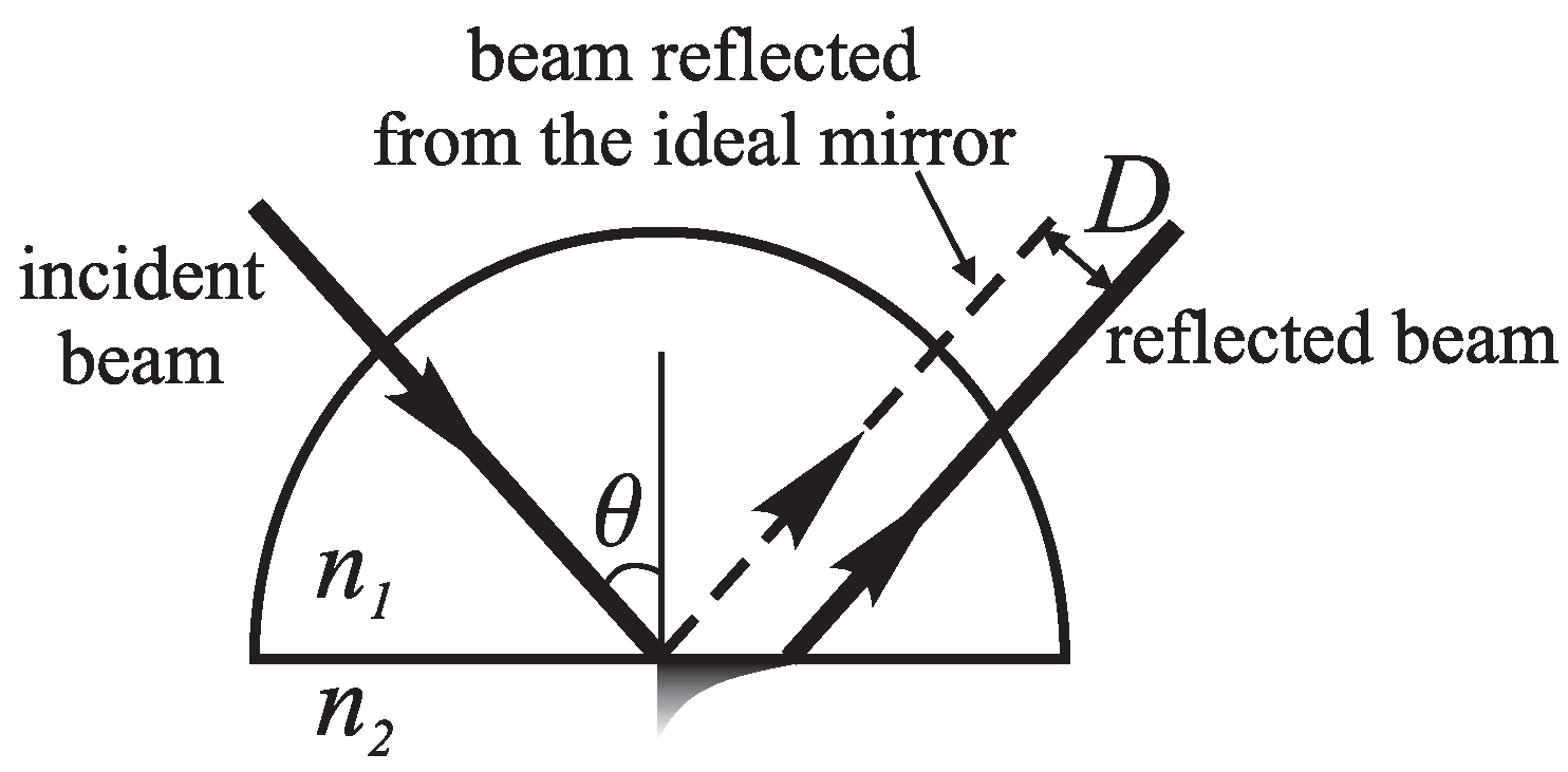
The Goos–Hänchen effect has been known since 1947 [30], when Goos and Hänchen first discovered the deflection of the propagation of a reflected light beam from the trajectory predicted by geometric optics (Figure 6) during total internal reflection from the surface of the glass prism.
After this, the Goos–Hänchen effect was discovered and extensively studied for electromagnetic waves propagating in various media [31,32,33,34,35], including surface plasmon polaritons at the boundary of a metal film [36]. A Goos–Hänchen shift significantly increases at resonances of the angular dependence of the reflection coefficient phase. The Goos–Hänchen shift D can be obtained as: where is the wavelength, is the phase of the complex reflection coefficient, and is the angle of incidence [37]. At the critical angle, the reflection coefficient varies rather smoothly and the values of the Goos–Hänchen effect turn out to be small. In contrast, it is possible to obtain significant values of the Goos–Hänchen shift at the angular vicinity of the Brewster angle [38], the edge of the photonic band gap in photonic crystals [39] and especially near the resonance of surface plasmons on a metal film [40]. Since the spectral–angular resonances of the BSW can be chosen to be substantially narrower than the resonances of surface plasmons in the visible spectral range, this caused an interest in the detection and research of the Goos–Hänchen effect near the resonance of the BSW.
The study was performed in [26,28]. Multilayer structures consisting of 9, 11, 13 and 15 ZrO/SiO bilayers with refractive indices of 1.9 and 1.46 were chosen as one-dimensional photonic crystal samples. A Kretschmann scheme of an attenuated total internal reflection prism configuration was used to couple the incident s-polarized light to the BSW at the photonic crystal–air interface. The Goos–Hänchen effect caused by the BSW was obtained in two ways: from the experimentally measured BSW resonance spectra, and by fluorescence microscopy in the far field. The microimages shown in the Figure 7 made it possible to observe both the scattered image of the BSW and the fluorescence image of the spots of the beams incident and reflected from the photonic crystal. Both estimates gave results that are satisfactorily consistent within the experimental error.
In fluorescent images, it is seen that with a single “inc” spot of the incident beam, the reflected beam “ref ” is divided into two parts, shifted relative to each other. Analogous to the interpretation of the Fano resonance in the reflectance of a photonic crystal during the BSW excitation, these two parts are associated with the resonant part of the incident beam that passes into the BSW, and the nonresonant one that is totally reflected from the surface.
The distance between these two parts can be regarded as the Goos–Hänchen shift caused by the BSW. It has been shown that the BSW-induced Goos–Hänchen shift significantly depends on the Q-factor of the BSW resonance. The maximum shift observed in Ref. [26] was 66 m or 125 wavelengths of incident light, that is, at least two times larger than the effect observed for surface plasmons [36,40]. Later, in higher-quality photonic crystal systems, even larger values of the Goos–Hänchen shift were obtained [41]. This huge Goos–Hänchen effect driven by the BSW gives a way to new types of planar photonic devices, as spectrally and angularly dependent spatial modulators of the light beam that can be easily controlled and able to move the beam hundreds of microns. The optical sensors using the Goos–Hänchen effect [42,43] also can be upgraded with BSWs substituting the surface plasmons.
5. The BSW-Induced Magneto-Optics
Magneto-optical effects, for example the Faraday and Kerr effects, are actively used to control the light polarization and intensity [44]. The magnitude of these effects is small, but it can be significantly enhanced near narrow optical resonances in the structures [45,46,47,48,49,50,51]. An appropriate resonant optical state for this purpose is the Bloch surface wave in magneto-photonic crystals (MPCs). The possibility of using BSWs at the MPC to control the parameters of the light polarization was studied in [52,53]. The paper [52] is devoted to a numerical study of the Faraday rotation at the spectral position of the BSW resonance and to the research of the BSW magneto-optical switching in MPCs. The concept of using the BSW in MPCs to control all parameters of light polarization through the external magnetic field application was proposed and experimentally demonstrated in the paper [53].
In these studies, the structures of the MPC, consisting of alternating quarter-wave layers of iron yttrium garnet and fused quartz, were considered. The thickness of the upper layer was selected specifically in accordance with the conditions of the BSW excitation in the structure. For the experimental study, the MPC structure was fabricated by ion-beam sputtering of Bi-substituted yttrium iron garnet (Bi:YIG) and fused quartz targets onto a substrate made of gadolinium gallium garnet. The sample was annealed after deposition of each pair of layers.
Numerical studies were carried out using Berreman’s transfer matrix approach [54,55]. The reflectance and the Faraday rotation angle of the light reflected from the MPC, depending on the angle of incidence and the wavelength, were numerically studied.
In the experiment, spectra of the reflectance and Faraday rotation angle were measured using the optical reflectance spectroscopy technique. The sample of the MPC was illuminated by the radiation of a halogen lamp. Light passed through a polarizer to set the required polarization of light. The MPC was illuminated through a glass prism in the Kretschmann scheme of total internal reflection. A magnetic field with strength of about 1 kOe was created at the sample using a permanent magnet. Light reflected from the sample was detected with a spectrometer. To determine the polarization of the reflected light, an analyzer was placed in front of the detector and the dependence of reflectance on the angle of the analyzer was measured. The Faraday rotation angle was calculated as half of the phase difference, obtained from approximation of data with Malus’ law for opposite directions of the magnetic field.
The parameters of the MPC were chosen in such a way that if s-polarized light illuminates the sample behind the light line, the BSW appears in the photonic band gap. If the incident light has the p-polarization, the waveguide mode (WGM) is excited in the same spectral range. Both the experimentally measured and numerically calculated spectra of the Faraday rotation have Fano-shaped resonance at the spectral position of the BSW excitation. The shape of Fano resonance in a Faraday rotation spectrum depends on the relative spectral positions of the resonances of the BSW and WGM. While the incident angle increases, positions of the BSW and the WGM resonances become closer and finally pass through one another. During this process, the Fano resonance in Faraday rotation spectra changes from an asymmetric shape to a symmetric one. Thus, the Faraday rotation spectra depend not only on the BSW resonance in the structure, but also on the interaction between the BSW and the WGM modes. The Fano-shaped resonances in the Faraday rotation spectra can be interpreted by considering the general properties of the WGM and BSW. The reflected light phase changes as a function of the wavelength near the resonances of the WGM and BSW. The phase changes slow at the WGM spectral position because of low Q-factor of the resonance, and have a sharp jump at the BSW resonance, where the Q-factor is high. The polarization rotation angle of the reflected wave appears from the phase difference between s- and p-polarized reflected light, which explains the change in the sign of the Faraday rotation near the resonance of the BSW. Theoretically, the Faraday rotation of light reflected from the MPC at the wavelength of BSW resonance can reach the value of [56].
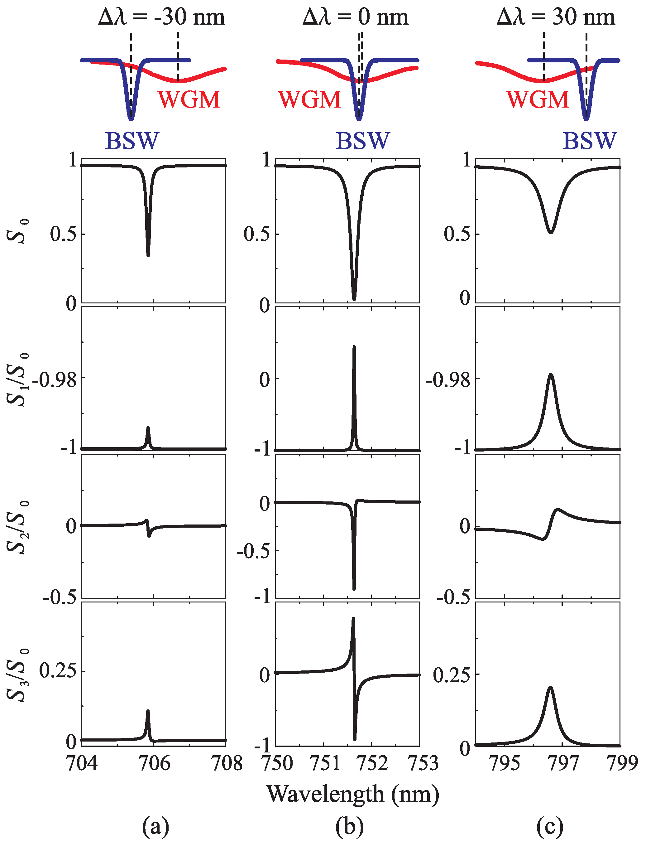
Besides the Faraday rotation, Ref. [53] also considers other transformations of light polarization, such as transition of the linear polarization to the elliptical one. To describe these polarization changes, the spectral dependencies of Stokes parameters were numerically studied. Obtained Stokes parameter spectra are shown in Figure 8. Three typical cases were considered. In the first case, the position of the BSW resonance is blue-shifted for 30 nm relative to the resonance of the WGM (Figure 8a). In the second case, the position of the BSW resonance is shifted 30 nm to the higher wavelengths (Figure 8c). The third case corresponds to the situation when the BSW and WGM have the same spectral position (Figure 8b). The parameter is the reflectance of light from the sample. The angle of Faraday rotation can be achieved from the first and second Stokes parameters as . The Stokes parameter corresponds to the ellipticity of reflected light. The shapes of spectra and show that Faraday rotation of reflected light becomes higher while the BSW coupling is more effective. The reflected light ellipticity increases simultaneously (Figure 8, spectrum). When the WGM and BSW have the same wavelength of excitation, the ellipticity equals 1, so the reflected light is circularly polarized. While the BSW coupling becomes less effective, the values of Stokes parameters significantly decrease (Figure 8a,c). The influence of the WGM and its spectral position relative to the BSW manifest themselves in the spectral behavior of the parameter . If the BSW excites at shorter wavelength than the WGM, the spectrum has the shape of an asymmetric Fano resonance (Figure 8a). For the BSW excited at a longer wavelength than the WGM, the Fano resonance in the spectrum takes an inverted asymmetric shape (Figure 8c). Therefore, the Faraday rotation angle changes sign when the dispersion curves of the BSW and WGM resonances intersect each other. In fact, the polarization of light can be controlled by a magnetic field applied to the MPC structures supporting the excitation of the BSW. Due to the excitation of the BSW, studied MPC structures have a great potential for applications as a magnetically-controlled wave-plate of variable thickness.
6. The BSW Application in Microparticle Optical Trapping
The BSWs in photonic crystals are also promising in the field of optical control. Optical forces have been used for more than 40 years in laboratories for trapping, moving and studying nano- and microparticles, biological molecules and cells [57,58,59,60,61]. Single-beam gradient force optical traps, or optical tweezers, have become a routine tool for physical and biological research [62,63]. The principle of operation of optical tweezers is based on the action of the ponderomotive force, which moves the particle with a refractive index higher than that of the surrounding medium along the intensity gradient of electromagnetic radiation. In optical tweezers, when the laser radiation is focused, this gradient is directed to the centre of the waist. However, an electromagnetic gradient can be created not only in the waist region of focused laser radiation. The possibility of trapping and moving nanoparticles and microparticles using an evanescent field that appeared with total internal reflection from a smooth surface and in optical waveguides was shown [64,65,66,67]. Large values of optical field gradients can be achieved by using optical resonances of surface plasmons on metallic films and in plasmonic structures [68,69,70,71,72,73]. However, local heating under the influence of optical radiation usually makes complicated the use of metal structures. The BSWs in photonic crystals can be an alternative to surface plasmons. They also provide a substantial increase of the optical field near the photonic crystal surface. At the same time, photonic crystals can be entirely made of transparent materials and devoid of heating problems. The force action of the BSW field in photonic crystals on micro-objects is considered in [74,75,76]. It is shown that this effect can be used for optical control. The force was experimentally determined using photon-force microscopy, which is based on the technique of optical tweezers. The method of photon-force microscopy consists of detecting the displacement of a test particle in an optical trap under the action of an external force: the higher the force, the greater the displacement. In fact, the trap acts as a dynamometer on the microscale in this method. The equilibrium position of the particle is determined by the balance between the external force and the restoring force, which tends to return the particle to the centre of the trap.
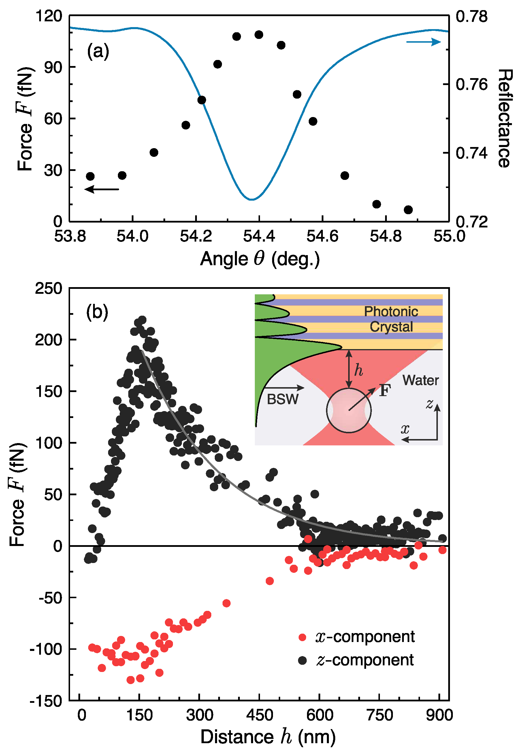
In the experiments described in Refs. [74,75,76], a small amount of 10 vol. % aqueous suspension of 1 m test particles of polystyrene was placed onto the surface of a photonic crystal on a glass substrate and hermetically covered with a cover glass, leaving a gap for the suspension with thickness of several tens of micrometers (see the inset in Figure 9). A particle from the suspension could be trapped at a controlled distance from the surface of the photonic crystal. The photonic crystal consisted of five pairs of ZrO/SiO layers with an optical thickness of each layer of 300 nm. The BSW at a wavelength of 532 nm could be excited at the photonic crystal/water boundary in a Kretschmann scheme of attenuated total internal reflection. To do this, s-polarized radiation from a continuous Nd:YAG laser with double frequency was directed to the inner surface of the photonic crystal through a glass prism. The power of the incident radiation was 1.6 kW/cm, with a beam divergence of 0.4 degrees. When the BSW was excited, the force from the BSW field began to act on a particle trapped near a photonic crystal surface. It caused a displacement of the average position of the particle in the optical trap. Figure 9 shows the experimentally obtained dependence of the force acting on the particle from the BSW. The BSW attracts the particle to the surface, and also pushes the particle along its propagation direction. The attraction is due to the gradient forces formed by the BSW electric field that exponentially decreases into the environment. The displacement of the particle along the surface is due to the forces associated with the scattering of this field by the particle. The presence of surfactants prevented adhesion of the particle to the surface. This nature of the BSW optical force led to the fact that when the optical trap was turned off, the particle began to move along the BSW propagation direction at a constant speed of about 7 m/s. This experiment shows the possibility of controlling the particle by the field of the BSW.
7. Conclusions
In conclusion, we considered optical and magneto-optical effects observed in photonic crystals during the Bloch surface wave excitation and propagation. Some effects taking place at the light reflection and scattering from the photonic crystal surface were described. We discussed the enhancement of the Goos–Hänchen effect caused by the BSW. The magneto-optical Faraday effect induced by the BSW was reviewed. The research concerning the optical forces the BSW exerts on the dielectric micro-objects were described. The optical effects induced and controlled by the BSW that are reviewed here have values comparable or superior to the analogues currently used in prototypes and commercial devices. With the undoubted merits of BSWs, such as low material absorption and good control of the spectral–angular resonance position, BSWs are a good candidate for use in optoelectronic integrated devices implementing spatial light modulation, control of the polarization of light, optical trapping and mechanical control of micro-objects. BSWs have a great potential to become widespread in future photonic applications.
Acknowledgments
This work was partially supported by the Russian Ministry of Education and Science (Grant No. 14.W03.31.0008) and the the Russian Foundation for Basic Research (Grants No. 17-08-01716, 15-32-70012, 18-02-00880) and the Moscow city Government.
Conflicts of Interest
The authors declare no conflict of interest.
References
- Yeh, P.; Yariv, A. Optical Surface waves in periodic layered media. Appl. Phys. Lett. 1978, 32, 104–105. [Google Scholar] [CrossRef]
- Robertson, W.M.; May, M.S. Surface electromagnetic wave excitation on one-dimensional photonic band gap arrays. Appl. Phys. Lett. 1999, 74, 1800–1802. [Google Scholar] [CrossRef]
- Agranovich, V.; Mills, D. (Eds.) Surface Polaritons: Electromagnetic Waves at Surfaces and Interfaces; Modern Problems in Condensed Matter Sciences; Elsevier: Amsterdam, The Netherlands, 1982; Volume 1. [Google Scholar]
- Han, Z.; Bozhevolnyi, S.I. Chapter 5—Waveguiding with Surface Plasmon Polaritons. In Modern Plasmonics; Richardson, N., Holloway, S., Eds.; Handbook of Surface Science; North-Holland: Amsterdam, The Netherlands, 2014; Volume 4, pp. 137–187. [Google Scholar]
- Dubey, R.; Barakat, E.; Häyrinen, M.; Roussey, M.; Honkanen, S.K.; Kuittinen, M.; Herzig, H.P. Experimental investigation of the propagation properties of bloch surface waves on dielectric multilayer platform. J. Eur. Opt. Soc.-Rapid Publ. 2017, 13, 5. [Google Scholar] [CrossRef]
- Badugu, R.; Mao, J.; Blair, S.; Zhang, D.; Descrovi, E.; Angelini, A.; Huo, Y.; Lakowicz, J.R. Bloch Surface Wave-Coupled Emission at Ultraviolet Wavelengths. J. Phys. Chem. C 2016, 120, 28727–28734. [Google Scholar]
- Kim, M.S.; Lahijani, B.V.; Descharmes, N.; Straubel, J.; Negredo, F.; Rockstuhl, C.; Häyrinen, M.; Kuittinen, M.; Roussey, M.; Herzig, H.P. Subwavelength Focusing of Bloch Surface Waves. ACS Photonics 2017, 4, 1477–1483. [Google Scholar] [CrossRef]
- Konopsky, V.N.; Alieva, E.V. A biosensor based on photonic crystal surface waves with an independent registration of the liquid refractive index. Biosens. Bioelectron. 2010, 25, 1212–1216. [Google Scholar] [CrossRef] [PubMed]
- Konopsky, V.; Karakouz, T.; Alieva, E.V.; Vicario, C.; Sekatskii, S.K.; Dietler, G. Photonic Crystal Biosensor based on Optical Surface Waves. Sensors (Basel) 2013, 13, 2566–2578. [Google Scholar] [CrossRef] [PubMed]
- Li, Y.; Yang, T.; Song, S.; Pang, Z.; Du, G.; Han, S. Phase properties of Bloch surface waves and their sensing applications. Appl. Phys. Lett. 2013, 103, 1–4. [Google Scholar] [CrossRef]
- Sinibaldi, A.; Anopchenko, A.; Rizzo, R.; Danz, N.; Munzert, P.; Rivolo, P.; Frascella, F.; Ricciardi, S.; Michelotti, F. Angularly resolved ellipsometric optical biosensing by means of Bloch surface waves. Anal. Bioanal. Chem. 2015, 407, 3965–3974. [Google Scholar] [CrossRef] [PubMed]
- Descrovi, E.; Frascella, F.; Sciacca, B.; Geobaldo, F. Coupling of surface waves in highly defined one-dimensional porous silicon photonic crystals for gas sensing applications. Appl. Phys. Lett. 2007, 91, 241109–241111. [Google Scholar] [CrossRef]
- Michelotti, F.; Sciacca, B.; Dominici, L.; Quaglio, M.; Descrovi, E.; Giorgis, F.; Geobaldo, F. Fast optical vapour sensing by Bloch surface waves on porous silicon membranes. Phys. Chem. Chem. Phys. 2010, 12, 502–506. [Google Scholar] [CrossRef] [PubMed]
- Descrovi, E.; Giorgis, F.; Dominici, L.; Michelotti, F. Experimental observation of optical bandgaps surface electromagnetic waves periodically corrugated one-dimensional nitride photonic crystal. Opt. Lett. 2008, 33, 243–245. [Google Scholar] [CrossRef] [PubMed]
- Sfez, T.; Descrovi, E.; Dominici, L.; Nakagawa, W.; Michelotti, F.; Giorgis, F.; Herzig, H. Near-field analysis of surface electromagnetic waves in the bandgap region of a polymeric grating written on a one-dimensional photonic crystal. Appl. Phys. Lett. 2008, 93, 061108. [Google Scholar] [CrossRef]
- Kovalevich, T.; Boyer, P.; Suarez, M.; Salut, R.; Kim, M.S.; Herzig, H.P.; Bernal, M.P.; Grosjean, T. Polarization controlled directional propagation of Bloch surface wave. Opt. Express 2017, 25, 5710–5715. [Google Scholar] [CrossRef] [PubMed]
- Wang, R.; Wang, Y.; Zhang, D.; Si, G.; Zhu, L.; Du, L.; Kou, S.; Badugu, R.; Rosenfeld, M.; Lin, J.; Wang, P.; Ming, H.; Yuan, X.; Lakowicz, J. Diffraction-Free Bloch Surface Waves. ACS Nano 2017, 11, 5383–5390. [Google Scholar] [CrossRef] [PubMed]
- Angelini, A.; Barakat, E.; Munzert, P.; Boarino, L.; De Leo, N.; Enrico, E.; Giorgis, F.; Herzig, H.P.; Pirri, C.F.; Descrovi, E. Focusing and Extraction of Light mediated by Bloch Surface Waves. Sci. Rep. 2014, 4, 5428. [Google Scholar] [CrossRef] [PubMed]
- Descrovi, E.; Barakat, E.; Angelini, A.; Munzert, P.; Leo, N.D.; Boarino, L.; Giorgis, F.; Herzig, H.P. Leakage radiation interference microscopy. Opt. Lett. 2013, 38, 3374–3376. [Google Scholar] [CrossRef] [PubMed]
- Hung, Y.J.; Lin, I.S. Visualization of Bloch surface waves and directional propagation effects on one-dimensional photonic crystal substrate. Opt. Express 2016, 24, 16003–16009. [Google Scholar] [CrossRef] [PubMed]
- Yu, L.; Barakat, E.; Sfez, T.; Hvozdara, L.; Di Francesco, J.; Herzig, H.P. Manipulating Bloch surface waves in 2D: A platform concept-based flat lens. Light Sci. Appl. 2014, 3, e124. [Google Scholar] [CrossRef]
- Yeh, P.; Yariv, A.; Hong, C.S. Electromagnetic propagation in periodic stratified media. I. General theory. J. Opt. Soc. Am. 1977, 67, 423–438. [Google Scholar] [CrossRef]
- Soboleva, I.V.; Descrovi, E.; Dominici, L.; Michelotti, F.; Giorgis, F.; Fedyanin, A.A. Visualization of surface electromagnetic waves in one-dimensional photonic crystal by fluorescence dye. Proc. SPIE 2009, 7356, 73560E. [Google Scholar] [CrossRef]
- Meade, R.; Brommer, K.; Rappe, M.; Joannopoulos, J. Electromagnetic Bloch waves at the surface of a photonic crystal. Phys. Rew. B 1991, 44, 10961. [Google Scholar] [CrossRef]
- Michelotti, F.; Sinibaldi, A.; Munzert, P.; Danz, N.; Descrovi, E. Probing losses of dielectric multilayers by means of Bloch surface waves. Opt. Lett. 2013, 38, 616–618. [Google Scholar] [CrossRef] [PubMed]
- Soboleva, I.; Moskalenko, V.; Fedyanin, A. Giant Goos-Hanchen effect and Fano resonance at photonic crystal surfaces. Phys. Rev. Lett. 2012, 108, 123901. [Google Scholar] [CrossRef] [PubMed]
- Raether, H. Surface-Plasmons on Smooth and Rough Surfaces and on Gratings; Springer: Berlin, Germany, 1988. [Google Scholar]
- Moskalenko, V.; Soboleva, I.; Fedyanin, A. Surface waves-induced Goos-Hanchen effect enhancement in one-dimensional photonic crystals. JETP Lett. 2010, 91, 382–386. [Google Scholar] [CrossRef]
- Soboleva, I.; Descrovi, E.; Summonte, C.; Fedyanin, A.A.; Giorgis, F. Fluorescence emission enhanced by surface electromagnetic waves on one-dimensional photonic crystals. Appl. Phys. Lett. 2009, 94, 231122. [Google Scholar] [CrossRef]
- Goos, F.; Hänchen, H. Ein neuer und fundamentaler Versuch zur Totalreflexion. Ann. Phys. 1947, 436, 333–346. [Google Scholar] [CrossRef]
- De Haan, V.O.; Plomp, J.; Rekveldt, T.M.; Kraan, W.H.; van Well, A.A.; Dalgliesh, R.M.; Langridge, S. Observation of the Goos-Hänchen Shift with Neutrons. Phys. Rev. Lett. 2010, 104, 010401. [Google Scholar] [CrossRef] [PubMed]
- Wu, Z.; Zhai, F.; Peeters, F.M.; Xu, H.Q.; Chang, K. Valley-Dependent Brewster Angles and Goos-Hänchen Effect in Strained Graphene. Phys. Rev. Lett. 2011, 106, 176802. [Google Scholar] [CrossRef] [PubMed]
- Wild, W.; Giles, C. Goos-Hänchen shift from absorbing media. Phys. Rev. A 1982, 25, 2099–2101. [Google Scholar] [CrossRef]
- Merano, M.; Aiello, A.; Hooft, T.; Exter, M.P.; Eliel, E.R.; Woerdman, J.P. Observation of Goos-Hänchen shifts in metallic reflection. Opt. Express 2007, 15, 15928–15934. [Google Scholar] [CrossRef] [PubMed]
- Shadrivov, I.V.; Zharov, A.A.; Kivshar, Y.S. Giant Goos-Hänchen effect at the reflection from left-handed metamaterials. Appl. Phys. Lett. 2003, 83, 2713–2715. [Google Scholar] [CrossRef]
- Bonnet, C.; Chauvat, D.; Emile, O.; Bretenaker, F.; Floch, A.L. Measurement of positive and negative Goos-Hänchen effects for metallic gratings near Wood anomalies. Opt. Lett. 2001, 26, 666–668. [Google Scholar] [CrossRef] [PubMed]
- Artmann, K. Berechnung der Seitenversetzung des totalreflektierten Strahles. Ann. Phys. 1948, 437, 87–102. [Google Scholar] [CrossRef]
- Lai, H.M.; Chan, S.W. Large and negative Goos–Hänchen shift near the Brewster dip on reflection from weakly absorbing media. Opt. Lett. 2002, 27, 680–682. [Google Scholar] [CrossRef] [PubMed]
- Felbacq, D.; Moreau, A.; Smaâli, R. Goos-Hänchen effect in the gaps of photonic crystals. Opt. Lett. 2003, 28, 1633–1635. [Google Scholar] [CrossRef] [PubMed]
- Yin, X.; Hesselink, L.; Liu, Z.; Fang, N.; Zhang, X. Large positive and negative lateral optical beam displacements due to surface plasmon resonance. Appl. Phys. Lett. 2004, 85, 372–374. [Google Scholar] [CrossRef]
- Wan, Y.; Zheng, Z.; Kong, W.; Zhao, X.; Liu, Y.; Bian, Y.; Liu, J. Nearly three orders of magnitude enhancement of Goos-Hanchen shift by exciting Bloch surface wave. Opt. Express 2012, 20, 8998–9003. [Google Scholar] [CrossRef] [PubMed]
- Chen, C.; Lin, W.; Liao, L.; Lin, Z.; Chiang, H.; Leung, P.; Sijercic, E.; Tse, W. Optical temperature sensing based on the Goos-Hänchen effect. Appl. Opt. 2007, 46, 5347–5351. [Google Scholar] [CrossRef] [PubMed]
- Yin, X.; Hesselin, L. Goos-Hänchen shift surface plasmon resonance sensor. Appl. Phys. Lett. 2006, 89, 261108. [Google Scholar] [CrossRef]
- Inoue, M.; Fujikawa, R.; Baryshev, A.; Khanikaev, A.; Lim, P.B.; Uchida, H.; Aktsipetrov, O.; Fedyanin, A.; Murzina, T.; Granovsky, A. Magnetophotonic crystals. J. Phys. D Appl. Phys. 2006, 39, R151. [Google Scholar] [CrossRef]
- Belotelov, V.I.; Akimov, I.A.; Pohl, M.; Kotov, V.A.; Kasture, S.; Vengurlekar, A.S.; Gopal, A.V.; Yakovlev, D.R.; Zvezdin, A.K.; Bayer, M. Enhanced magneto-optical effects in magnetoplasmonic crystals. Nat. Nanotechnol. 2011, 6, 370–376. [Google Scholar] [CrossRef] [PubMed]
- Inoue, M.; Fujii, T. A theoretical analysis of magneto-optical Faraday effect of YIG films with random multilayer structures. J. Appl. Phys. 1997, 81, 5659. [Google Scholar] [CrossRef]
- Fedyanin, A.A.; Yoshida, T.; Nishimura, K.; Marowsky, G.; Inoue, M.; Aktsipetrov, O.A. Nonlinear magneto-optical Kerr effect in gyrotropic photonic band gap structures: Magneto-photonic microcavities. J. Magn. Magn. Mater. 2003, 258–259, 96–98. [Google Scholar] [CrossRef]
- Goto, T.; Dorofeenko, A.V.; Merzlikin, A.M.; Baryshev, A.V.; Vinogradov, A.P.; Inoue, M.; Lisyansky, A.A.; Granovsky, A.B. Optical Tamm States in One-Dimensional Magnetophotonic Structures. Phys. Rev. Lett. 2008, 101, 113902. [Google Scholar] [CrossRef] [PubMed]
- Grunin, A.A.; Zhdanov, A.G.; Ezhov, A.A.; Ganshina, E.A.; Fedyanin, A.A. Surface-plasmon-induced enhancement of magneto-optical Kerr effect in all-nickel subwavelength nanogratings. Appl. Phys. Lett. 2010, 97, 261908. [Google Scholar] [CrossRef]
- Clavero, C.; Yang, K.; Skuza, J.R.; Lukaszew, R.A. Magnetic field modulation of intense surface plasmon polaritons. Opt. Express 2010, 18, 7743–7752. [Google Scholar] [CrossRef] [PubMed]
- Chin, J.Y.; Steinle, T.; Wehlus, T.; Dregely, D.; Weiss, T.; Belotelov, V.I.; Stritzker, B.; Giessen, H. Nonreciprocal plasmonics enables giant enhancement of thin-film Faraday rotation. Nat. Commun. 2013, 4, 1599. [Google Scholar] [CrossRef] [PubMed]
- Romodina, M.N.; Soboleva, I.V.; Fedyanin, A.A. Magneto-optical switching of Bloch surface waves in magnetophotonic crystals. J. Magn. Magn. Mater. 2016, 415, 82–86. [Google Scholar] [CrossRef]
- Romodina, M.N.; Soboleva, I.V.; Musorin, A.I.; Nakamura, Y.; Inoue, M.; Fedyanin, A.A. Bloch-surface-wave-induced Fano resonance in magnetophotonic crystals. Phys. Rev. B 2017, 96, 081401(R). [Google Scholar] [CrossRef]
- Berreman, D.W. Optics in Stratified and Anisotropic Media: 4x4-Matrix Formulation. J. Opt. Soc. Am. 1972, 62, 502–510. [Google Scholar] [CrossRef]
- Bethune, D.S. Optical harmonic generation and mixing in multilayer media: Extension of optical transfer matrix approach to include anisotropic materials. J. Opt. Soc. Am. B 1991, 8, 367–373. [Google Scholar] [CrossRef]
- Inoue, M.; Levy, M.; Baryshev, A.V. Magnetophotonics: From Theory to Applications; Springer: Berlin, Germany, 2008; Volume 104. [Google Scholar]
- Ashkin, A. Acceleration and Trapping of Particles by Radiation Pressure. Phys. Rev. Lett. 1970, 24, 156–159. [Google Scholar] [CrossRef]
- Ashkin, A.; Dziedzic, J.M. Optical levitation by radiation pressure. Appl. Phys. Lett. 1971, 19, 283–285. [Google Scholar] [CrossRef]
- Ashkin, A.; Dziedzic, J.M.; Bjorkholm, J.E.; Chu, S. Observation of a single-beam gradient force optical trap for dielectric particles. Opt. Lett. 1986, 11, 288–290. [Google Scholar] [CrossRef] [PubMed]
- Ashkin, A.; Dziedzic, J.M.; Yamane, T. Optical trapping and manipulation of single cells using infrared laser beams. Nature 1987, 330, 769–771. [Google Scholar] [CrossRef] [PubMed]
- Ashkin, A.; Dziedzic, J. Optical trapping and manipulation of viruses and bacteria. Science 1987, 235, 1517–1520. [Google Scholar] [CrossRef] [PubMed]
- Neuman, K.C.; Block, S.M. Optical trapping. Rev. Sci. Instrum. 2004, 75, 2787–2809. [Google Scholar] [CrossRef] [PubMed]
- McGloin, D. Optical tweezers: 20 years on. Philos. Trans. R. Soc. A: Math. Phys. Eng. Sci. 2006, 364, 3521–3537. [Google Scholar] [CrossRef] [PubMed]
- Kawata, S.; Sugiura, T. Movement of micrometer-sized particles in the evanescent field of a laser beam. Opt. Lett. 1992, 17, 772–774. [Google Scholar] [CrossRef] [PubMed]
- Wada, K.I.; Sasaki, K.; Masuhara, H. Optical measurement of interaction potentials between a single microparticle and an evanescent field. Appl. Phys. Lett. 2000, 76, 2815–2817. [Google Scholar] [CrossRef]
- Gaugiran, S.; Gétin, S.; Fedeli, J.M.; Colas, G.; Fuchs, A.; Chatelain, F.; Dérouard, J. Optical manipulation of microparticles and cells on silicon nitride waveguides. Opt. Express 2005, 13, 6956–6963. [Google Scholar] [CrossRef] [PubMed]
- Ng, L.; Luff, B.; Zervas, M.; Wilkinson, J. Forces on a Rayleigh particle in the cover region of a planar waveguide. J. Lightw. Technol. 2000, 18, 388–400. [Google Scholar] [CrossRef]
- Juan, M.L.; Righini, M.; Quidant, R. Plasmon nano-optical tweezers. Nat. Photonics 2011, 5, 349–356. [Google Scholar] [CrossRef]
- Wong, H.M.K.; Righini, M.; Gates, J.C.; Smith, P.G.R.; Pruneri, V.; Quidant, R. On-a-chip surface plasmon tweezers. Appl. Phys. Lett. 2011, 99, 061107. [Google Scholar] [CrossRef]
- Zelenina, A.S.; Quidant, R.; Badenes, G.; Nieto-Vesperinas, M. Tunable optical sorting and manipulation of nanoparticles via plasmon excitation. Opt. Lett. 2006, 31, 2054–2056. [Google Scholar] [CrossRef] [PubMed]
- Volpe, G.; Quidant, R.; Badenes, G.; Petrov, D. Surface Plasmon Radiation Forces. Phys. Rev. Lett. 2006, 96, 238101. [Google Scholar] [CrossRef] [PubMed]
- Righini, M.; Volpe, G.; Girard, C.; Petrov, D.; Quidant, R. Surface Plasmon Optical Tweezers: Tunable Optical Manipulation in the Femtonewton Range. Phys. Rev. Lett. 2008, 100, 186804. [Google Scholar] [CrossRef] [PubMed]
- Grigorenko, A.N.; Roberts, N.W.; Dickinson, M.R.; Zhang, Y. Nanometric optical tweezers based on nanostructured substrates. Nat. Photonics 2008, 2, 365–370. [Google Scholar] [CrossRef]
- Shilkin, D.; Lyubin, E.; Soboleva, I.; Fedyanin, A. Trap position control in the vicinity of reflecting surfaces in optical tweezers. JETP Lett. 2014, 98, 644–647. [Google Scholar] [CrossRef]
- Shilkin, D.A.; Lyubin, E.V.; Soboleva, I.V.; Fedyanin, A.A. Direct measurements of forces induced by Bloch surface waves in a one-dimensional photonic crystal. Opt. Lett. 2015, 40, 4883–4886. [Google Scholar] [CrossRef] [PubMed]
- Shilkin, D.; Lyubin, E.; Soboleva, I.; Fedyanin, A. Near- field probing of Bloch surface waves in a dielectric multilayer using photonic force microscopy. J. Opt. Soc. Am. B 2016, 33, 1120–1127. [Google Scholar] [CrossRef]
Figure 1.
(a) Typical SEM image of one-dimensional photonic crystal, consisting of 6 SiO/TaO bilayers at the quartz substrate (from bottom to top); (b) Schematic of the Kretschmann configuration for the Bloch surface waves (BSW) coupling and detection; (c) Calculated normalized reflectivity map R() of the 1D photonic crystal illuminated in the Kretschmann configuration. Darker regions indicate lower reflectance. BSW dispersion curve is indicated by the arrow and SEW acronym. Reprinted with permission from I.V. Soboleva, E. Descrovi, L. Dominici, F. Michelotti, F. Giorgis, A.A. Fedyanin, Proceedings of SPIE 7356, 73560E (2009) [23].

Figure 2.
Calculated (left panel) and measured (right panel) fluorescence-induced visualization of BSW coupled using partial immersion. The calculated (gray line) and measured (open circles) reflectivity spectra of a bare photonic crystal demonstrate negligible resonance dip. The dip becomes more pronounced in calculated (black line) and measured (black circles) reflectivity spectra for the photonic crystal with Rhodamine 6G thin film at the surface. Reprinted with permission from I.V. Soboleva, E. Descrovi, L. Dominici, F. Michelotti, F. Giorgis, A.A. Fedyanin, Proceedings of SPIE 7356, 73560E (2009) [23].
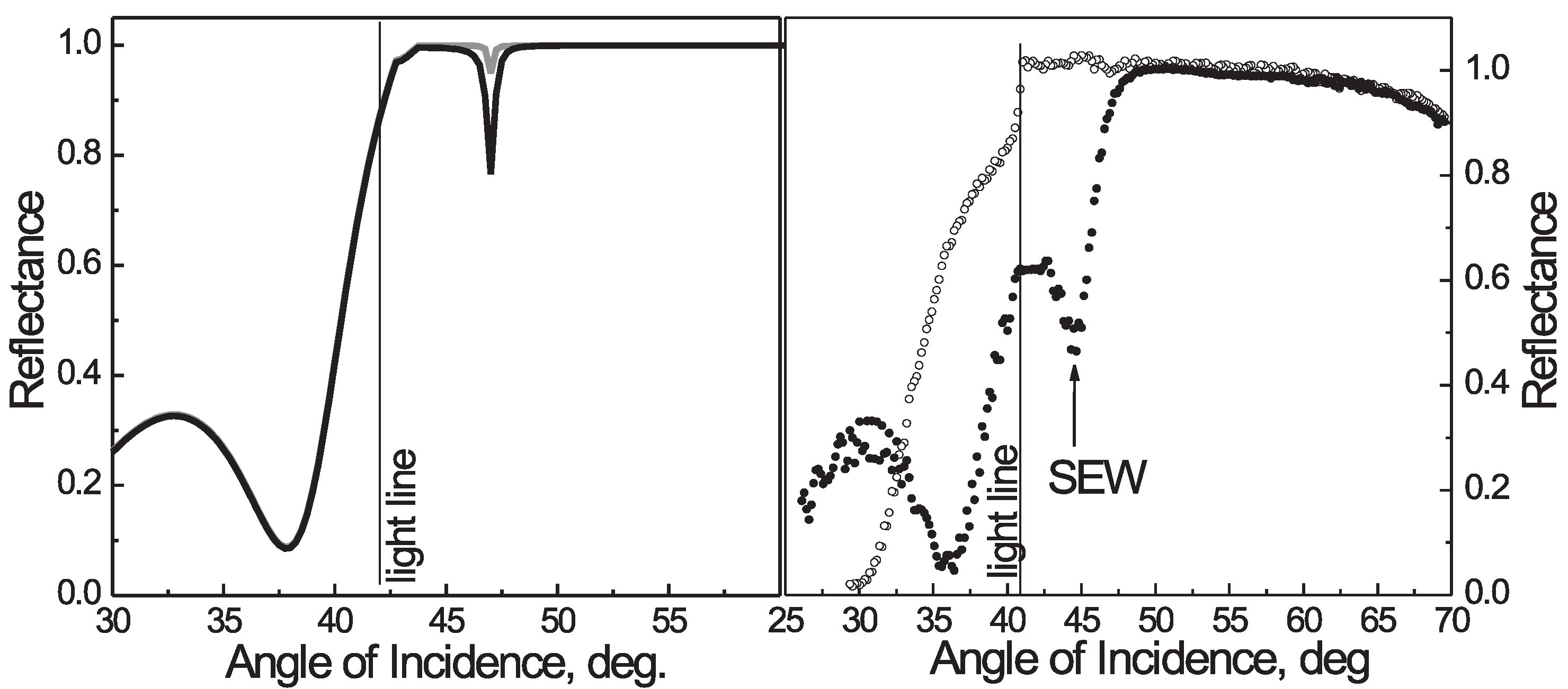
Figure 3.
(a) The model angular reflectance spectrum of the one-dimensional photonic crystal below the light line; (b–e) Experimental angular reflectance spectra (circles) of samples with 9, 11, 13 or 15 bilayers, and their fits according to numerical models (curves). Incident light is s-polarized. Dips in the spectra correspond to BSW excitation; (f) The model angular spectrum of the phase of the complex reflection coefficient. Reprinted with permission from I.V. Soboleva, V.V. Moskalenko, A.A. Fedyanin, Phys. Rev. Lett. 108, 123901 (2012). Copyright (2012) by the American Physical Society [26].
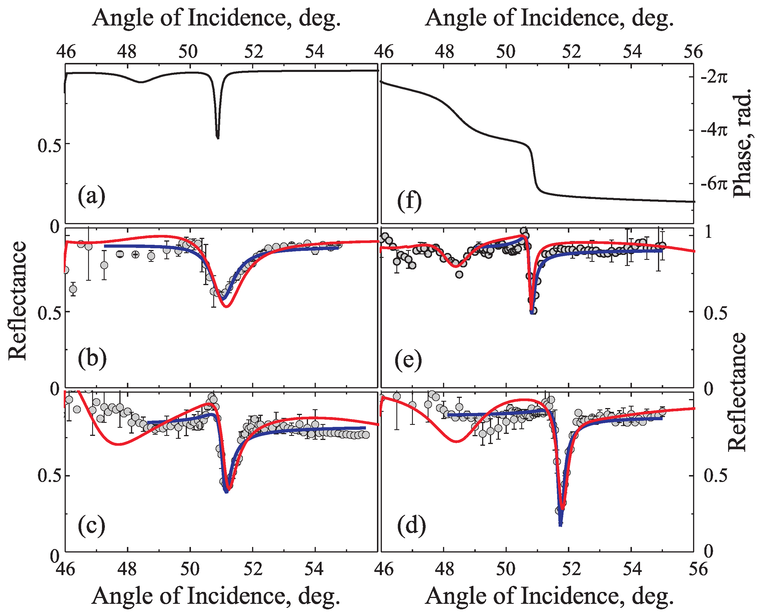
Figure 4.
(a) Schematic describing the scattering of the BSWs in the plane of the propagation on the surface of the photonic crystal in the Kretschmann configuration; k is the wave vector of the BSW, and k is the wave vector of the scattered component of the BSW. (b) Scattering pattern of surface electromagnetic waves in the total reflection direction. Reprinted from V.V. Moskalenko, I.V. Soboleva, A.A. Fedyanin, JETP Lett. 91, 382 (2010) with permission of Springer [28].
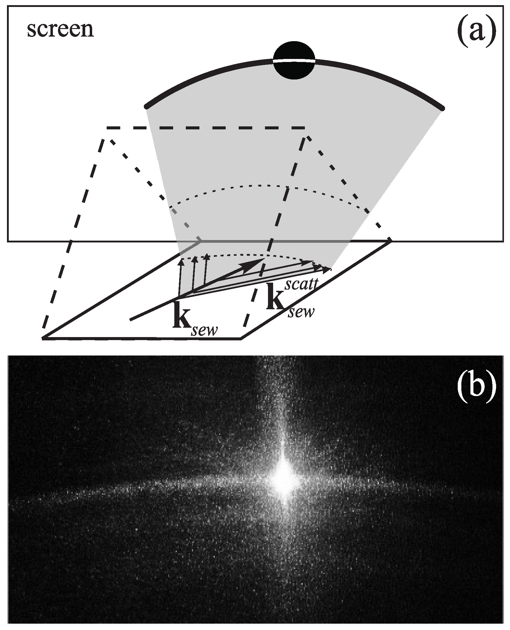
Figure 5.
BSW spatial distribution imaged by collecting (a) the light scattered by microdefects on the 1D photonic crystal surface, and (b) the fluorescence emitted by organic dyes on the 1D photonic crystal surface; (c) Fluorescence intensity profile along the BSW propagation direction. Reprinted from I.V. Soboleva, E. Descrovi, C. Summonte, A.A. Fedyanin, F. Giorgis, Appl. Phys. Lett. 94, 231122 (2009) with the permission of AIP Publishing [29].
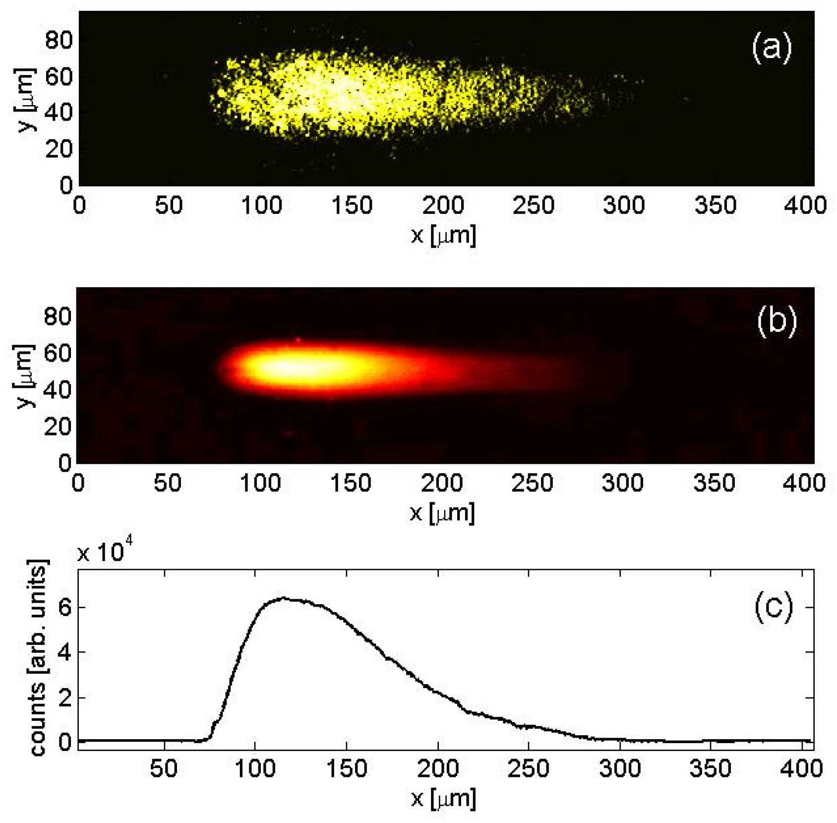
Figure 6.
Illustration of the Goos–Hänchen effect. The lateral shift D of the totally reflected beam () is observed. Reprinted from V.V. Moskalenko, I.V. Soboleva, A.A. Fedyanin, JETP Lett. 91, 382 (2010) with permission of Springer [28].
Figure 6.
Illustration of the Goos–Hänchen effect. The lateral shift D of the totally reflected beam () is observed. Reprinted from V.V. Moskalenko, I.V. Soboleva, A.A. Fedyanin, JETP Lett. 91, 382 (2010) with permission of Springer [28].

Figure 7.
Microimages of the surface of the photonic crystal illuminated with s- (a) and p-polarized (b) light; The objective lens is focused on the photonic crystal surface; (c) Fluorescence microimage of the reflected p-polarized beam. The objective is focused in the immersion liquid layer; (d–g) Fluorescence microimages of the s-polarized beam reflected from photonic crystals with different numbers of bilayers. The Goos–Hänchen shift is marked as D; (h–k) Fluorescence intensity profiles of s- (black line) and p-polarized (red line) beams. Left and right peaks correspond to incident (inc) and reflected (ref) spots. Reprinted with permission from I.V. Soboleva, V.V. Moskalenko, A.A. Fedyanin, Phys. Rev. Lett. 108, 123901 (2012). Copyright (2012) by the American Physical Society [26].
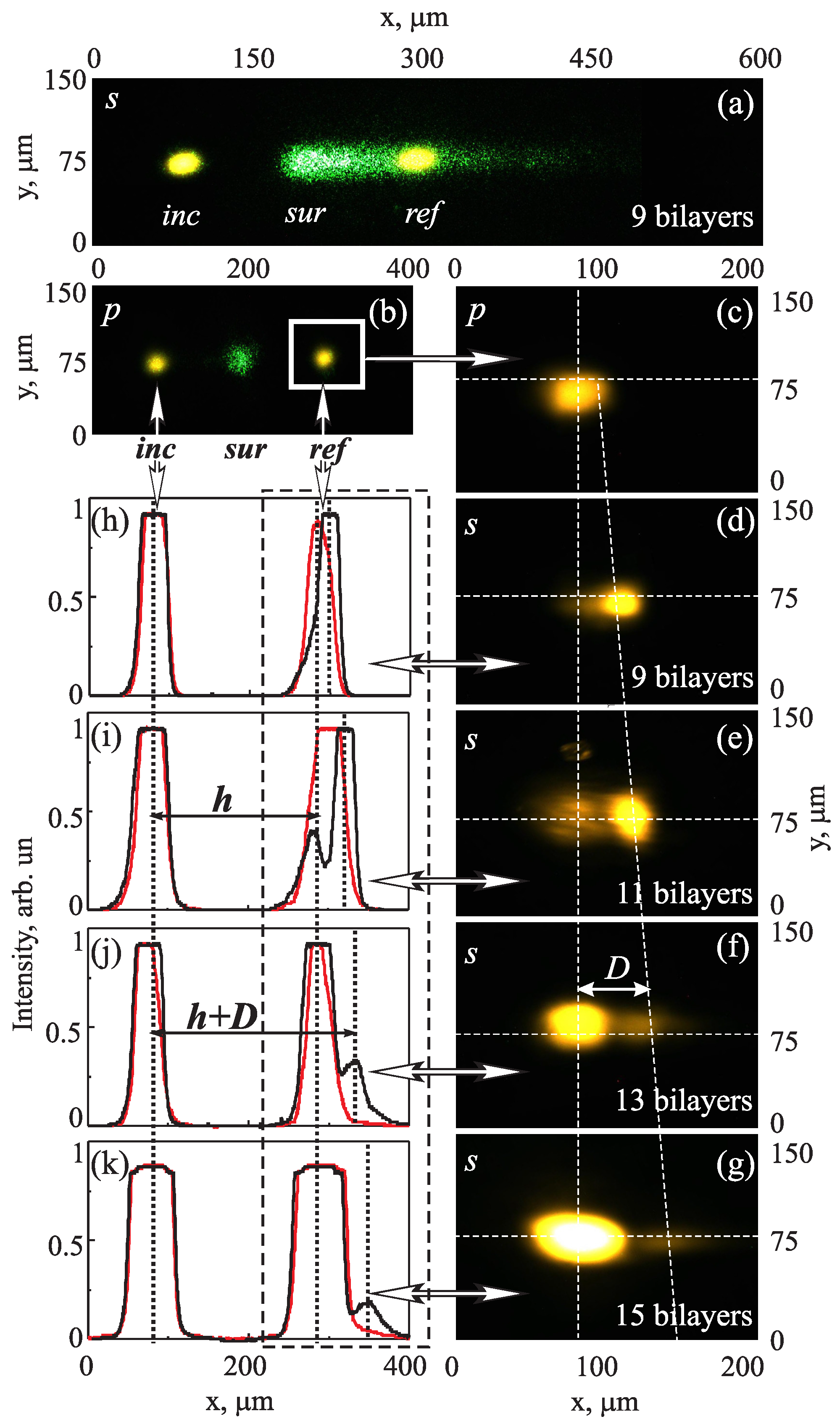
Figure 8.
Numerical spectra of the Stokes parameter and normalized Stokes parameters , and of light reflected by the magnetophotonic crystals in the presence of a magnetic field. The incident light is an s-polarized plane wave. Data are presented for the cases when the BSW resonance is (a) blue-shifted by 30 nm, (b) red-shifted by 30 nm relative to the waveguide mode (WGM) resonance, and (c) has the same spectral position as the WGM resonance. Reprinted with permission from M.N. Romodina, I.V. Soboleva, A.I. Musorin, Y. Nakamura, M. Inoue, A.A. Fedyanin, Phys. Rev. B 96, 081401(R) (2017). Copyright (2017) by the American Physical Society [53].

Figure 9.
(a) Experimental angular dependences of the photonic crystal (PC) reflectance (solid curve) and the magnitude of the BSW-generated force acting on a trapped microparticle at a PC/particle gap of approximately 300 nm (dots). Angle is the angle of incidence in the prism. The peak value corresponds to the BSW resonance angle; (b) x- (red dots) and z-coordinate (black dots) projection values of the BSW-generated force as a function of the distance between the trapped microparticle and the PC surface. Reprinted with permission from D.A. Shilkin, E.V. Lyubin, I.V. Soboleva, A.A. Fedyanin, Opt. Lett. 40, 4883 (2015). © 2015 Optical Society of America [75].

© 2018 by the authors. Licensee MDPI, Basel, Switzerland. This article is an open access article distributed under the terms and conditions of the Creative Commons Attribution (CC BY) license (http://creativecommons.org/licenses/by/4.0/).
Share and Cite
MDPI and ACS Style
Soboleva, I.V.; Romodina, M.N.; Lyubin, E.V.; Fedyanin, A.A. Optical Effects Induced by Bloch Surface Waves in One-Dimensional Photonic Crystals. Appl. Sci. 2018, 8, 127. https://doi.org/10.3390/app8010127
AMA Style
Soboleva IV, Romodina MN, Lyubin EV, Fedyanin AA. Optical Effects Induced by Bloch Surface Waves in One-Dimensional Photonic Crystals. Applied Sciences. 2018; 8(1):127. https://doi.org/10.3390/app8010127
Chicago/Turabian StyleSoboleva, Irina V., Maria N. Romodina, Evgeny V. Lyubin, and Andrey A. Fedyanin. 2018. "Optical Effects Induced by Bloch Surface Waves in One-Dimensional Photonic Crystals" Applied Sciences 8, no. 1: 127. https://doi.org/10.3390/app8010127
Note that from the first issue of 2016, this journal uses article numbers instead of page numbers. See further details here.