Review

Dental Applications of Optical Coherence Tomography (OCT) in Cariology

Department of Cariology, Endodontology and Periodontology, University of Leipzig, Liebigstraße 12, 04103 Leipzig, Germany
*
Author to whom correspondence should be addressed.
Appl. Sci. 2017, 7(5), 472; https://doi.org/10.3390/app7050472
Submission received: 10 February 2017 / Revised: 25 April 2017 / Accepted: 26 April 2017 / Published: 3 May 2017
(This article belongs to the Special Issue Development and Application of Optical Coherence Tomography (OCT))

Abstract

:
Across all medical disciplines, therapeutic interventions are based on previously acquired diagnostic information. In cariology, which includes the detection and assessment of the disease “caries” and its lesions, as well as non-invasive to invasive treatment and caries prevention, visual inspection and radiology are routinely used as diagnostic tools. However, the specificity and sensitivity of these standard methods are still unsatisfactory and the detection of defects is often afflicted with a time delay. Numerous novel methods have been developed to improve the unsatisfactory diagnostic possibilities in this specialized medical field. These newer techniques have not yet found widespread acceptance in clinical practice, which might be explained by the generated numerical or color-coded output data that are not self-explanatory. With optical coherence tomography (OCT), an innovative image-based technique has become available that has considerable potential in supporting the routine assessment of teeth in the future. The received cross-sectional images are easy to interpret and can be processed. In recent years, numerous applications of OCT have been evaluated in cariology beginning with the diagnosis of different defects up to restoration assessment and their monitoring, or the visualization of individual treatment steps. Based on selected examples, this overview outlines the possibilities and limitations of this technique in cariology and restorative dentistry, which pertain to the most clinical relevant fields of dentistry.

1. Introduction

Caries is still the most common chronic disease worldwide. Although prevention is generally possible, carious lesions are still one of the main reasons for dental treatment. In order to have an approach to prevent or causally treat caries, a clear diagnosis of the relevant findings in the oral cavity is necessary. Currently, visual and radiologic inspections are two standard techniques for the clinical detection, assessment and monitoring of carious lesions and dental restorations [1,2]. Although the “International Caries Detection and Assessment System” (ICDAS II) has helped to standardize visual diagnosis [3], the validity and reproducibility of lesion assessment is in need of improvement [4,5]. In particular, very early incipient demineralizations within outer enamel layers remain invisible, or cannot be correctly assessed, and radiography generally fails (Figure 1 and Figure 2).
Caries is still one of the main reasons for invasive restorative treatment [6]. Today, it is a primary objective in oral health care to preserve as much of the healthy tooth structure as possible. Therefore, early non- or minimally-invasive treatment options are becoming more important, thus placing higher demands on diagnostic tools as it is no longer sufficient to detect already extended carious lesions or cavitations. Rather, a goal is to recognize lesions, or other defects at their earliest possible stage, and to assess reproducibly whether they progress or not. Early lesion manifestations could be stabilized, or remineralization could even be initiated [7,8,9]. Traditional caries diagnostic methods like visual-tactile detection and radiography cannot achieve these objectives. X-ray diagnosis, in particular, has limitations and drawbacks: the exposure to ionizing radiation, the interpretation failures due to superpositioning effects, and a low sensitivity [10] that hinders the early detection and monitoring of minor pathological changes. Recently, innovative methods based on fluorescence [11], impedance spectroscopy, or digital infrared-transillumination have been implemented in caries diagnosis [12]. However, even these techniques were not able to solve the referred challenges and showed deficits in both sensitivity and specificity [1,13]. Therefore, there is still a medical need for procedures which could display early caries lesions and their progression. Initial findings concerning OCT suggested that different expressions of lesions, starting with very early demineralizations, could be detected. A threshold independent assessment of the validity by ROC analysis is aimed for the future to clarify whether a separation between sound and diseased is possible over the entire spectrum of carious lesions [14].
Furthermore, there is a substantial need for the assessment of dental restorations, which is technically demanding. Challenges include quality evaluation in terms of material homogeneity (bubble formation within material or at increments), or the detection of material overhangs at restoration margins. Currently there are no suitable methods available to enable dentists to self-check the quality of intermediate steps during restoration placement. Moreover, it is important to have the possibility to assess the bond at restoration margins and along the tooth-restoration interface, as well as to detect carious lesions adjacent to restorations (secondary caries) and compare different restoration materials in clinical trials or in in vitro studies. Today, the in vivo evaluation of marginal integrity can only be performed visually [15,16] and by a sensitive technique with a time-consuming quantitative margin analysis using scanning electron microscopy (SEM) [17]. However, the detection of early lesions adjacent to restorations is still a challenge [1].
Against the background of these demands, optical coherence tomography seems to be a promising technique. The method, which is based on low coherence interferometry, was first presented by Huang et al. [18]. In medicine, OCT is currently primarily used in ophthalmology for evaluating the pathological changes in retinal layers and the optic nerve [19,20,21,22]. Further applications are found in dermatology [23,24] and cardiology [25]. The first images of human dental tissues were presented by Colston et al. [26,27] and Feldchtein et al. [28]. Since then, the number of studies using OCT have increased markedly [29,30]. Seven features which make it particularly suitable for clinical application are non-invasive action avoiding radiation-induced tissue damage; easy to understand cross-sectional and 3D-images of soft and hard tissues; as well as defects at a very early stage with high spatial resolution. Structural changes can be obtained qualitatively as well as quantitatively. In particular, high speed data acquisition allows real-time imaging in vitro, ex vivo and in vivo [9,30].
Although OCT has been widely used in dental research, it nevertheless stands at the beginning of its application career. Numerous functional OCT systems [31,32], methodological extensions (e.g., polarization sensitive OCT [10]), as well as evaluation methods have been described [31,32,33], and also show the potential of this technology in characterizing specific material characteristics [33], or to improve the optical performance of the method, such as detection sensitivity or depth penetration [31,34]. This review presents applications of optical coherence tomography in the field of cariology, which includes subsections on caries prevention, detection, and assessment of carious lesions, as well as caries therapy. Particular focus is placed on restoration assessment and monitoring of the tooth-restoration bond.

2. Optical Coherence Tomography—The Methods

In biomedical and clinical research, the Fourier-domain optical coherence tomography (FD-OCT) is the technique currently applied and has two approaches: swept source OCT (SS-OCT) and the spectrometer-based system (spectral domain OCT, SD-OCT). Both approaches, which are based on low-coherence interferometry, have been well described in numerous publications [8,26,31,32,35]. The light from the source is split into a sample and a reference arm (Michelson interferometer configuration). The back reflected light from the sample (sample arm) and the reference mirror interfere with each other, and the resulting signal (spectrum) is then recorded by the detector.
In contrast, SS-OCT uses a frequency sweeping laser source combined with a photo diode; and SD-OCT applies a wideband laser source in combination with a spectrometer to split the interference signal into single wavelengths. After Fourier transform of the signal, a depth profile of backscattering along a perpendicular line to the object surface is generated (A-scan). The point-by-point scanning of the OCT beam across the sample produces 2D cross-sectional images (B-scans), and the line-by-line scanning generates a series of 2D images from which 3D image stacks can be created (Figure 3). OCT enables images to be generated from the different absorption and scattering of light of various material components in hard and soft tissues. Image contrast arises in areas with structures of different refractive index and light absorption, such as tooth-restoration interfaces, gaps, bubbles, material cracks, or porous areas in carious lesions [8,29,31].
The scenarios presented in this article are based on both SS- and SD-OCT. The techniques produce images non-invasively and at high-speed, allowing real-time imaging, and provide high axial and lateral resolution in the micrometer range. Dental structures and restorations can be imaged up to a depth of 2–2.5 mm thanks to the translucency and specific refractive indices of dental hard tissues (ndentin: 1.48–1.80; nenamel: 1.45–1.61, own measurements) and composite restoration materials (ncomposite: 1.42–1.63, own readings) in the range 1325 nm of near infrared light. In this wavelength range the transparency of enamel is highest [31] with high axial resolution at the same time. The refractive indices of lesions vary widely depending on the demineralization degree such as the values of natural carious enamel lesions. Usually these exceeded the values of the adjacent sound enamel up to +16% (own data).
The following setups were used in our lab:
SD-OCT: TELESTO SP II or SP 5, Thorlabs GmbH, Dachau, Germany (Figure 4a).
Recording parameters in vitro, ex vivo and in vivo were: center wavelength 1310 ± 107 nm; sensitivity ≤106 dB; axial/lateral resolution <7.5 (air)/15 µm; field of view maximum 9 mm × 9 mm × 3.5 mm (air, pixel size 700 × 700 × 512 or 1024); imaging speed 76/91 kHz (in vivo) or 48–91 kHz (in vitro, ex vivo); A-Scan average 1 (in vivo) or 1–5 (in vitro, ex vivo); spot size 20 µm; and power on sample 3 mW.
SS-OCT: SS-OCT, OCS 1300SS, Thorlabs Inc., Newton, NJ, USA (Figure 4b).
The parameters of the OCT equipment in vitro, ex vivo and in vivo were: center wavelength 1325 ± 100 nm; sensitivity 100 dB; axial/lateral resolution 12 (air)/25 µm; field of view maximum 10 mm × 10 mm × 3 mm (pixel size 512 × 512 × 512); imaging speed 16 kHz; A-Scan average 1; and power on sample 4.5 mW.
In vitro/ex vivo studies: OCT signals were verified within a predefined region of interest (ROI) by comparison with corresponding X-ray microtomography images (µCT, Skyscan 1172-100-50, Bruker MicroCT, Kontich, Belgium); and after sectioning specimens with images from the reference methods transverse microradiography (TMR, PW 3830/40, Philips, Amsterdam, The Netherlands); scanning electron microscopy (SEM, 5 kV, Phenom, Phenom World, Eindhoven, The Netherlands); spinning disc confocal laser microscopy (SDCM, Smartproof 5, Carl Zeiss Microscopy, Oberkochen Germany); and different modes of light microscopy.
In vitro/ex vivo studies were performed on extracted human teeth. The teeth were sound or had caries lesions, were unrestored or restored with composite. The focus on the specimen was set on a ROI and the surface was dried using a cotton pellet to leave it moist with no visible water droplets (controlled hydrated condition). 2D cross-sectional images of the ROI and 3D image stacks were recorded and images processed (ImageJ from version 1.45S; Wayne Rasband, NIH, Bethesda, MD, USA).
In vivo studies: Because of the geometric dimensions of the probes (diameter 34 mm, working distance about 42 mm), the imaging was limited to vestibular smooth surfaces of incisors, canines and premolars, after restorations and tooth surfaces were cleaned. The handheld and mechanically stabilized scanning probe was positioned at a rough right-angle to the restoration surface (Figure 4c). The restoration area was brought into focus and within 6 s, 2D cross-sectional images and 3D image stacks were generated and processed (ImageJ from version 1.45S).
The studies were conducted in accordance with the Declaration of Helsinki, and the protocols were approved by the Ethics Committee of the University of Leipzig. The extracted teeth were used with patients’ approvals (informed consents, protocol no. 299-10-04102010), and all subjects gave their informed consent for inclusion before they participated in the study (protocols no. 087/2003, 131-11-18042011, 196-14-14042014, 294-15-13072015).
With OCT, in vivo imaging is a challenge if dental hard tissues (enamel, dentin), which induce more scattering and containing less water, are to be displayed together with soft tissues (gingiva, pulp), which contain more water. The optical properties of these tissues, such as light scattering and absorption, are very diverse and also vary with imaging wavelength. One limitation of OCT is the shallow penetration depth, caused by signal attenuation due to scattering and absorption. Depth penetration can be enhanced by optimizing the center wavelength. In particular, in the presence of structures such as carious lesions which induce increased scattering, multiple scattering can further reduce imaging quality at deeper penetration depths. As well as the technical parameters of the OCT equipment, the center wavelength of the light source and the optical bandwidth are key determinants for axial resolution. For soft and hard tissues, there are characteristic dependences of wavelength of OCT signal attenuation [36]. Some authors suggested that an imaging window at 1700 nm offers an advantage over shorter wavelengths by increasing penetration depth as well as enhancing the image contrast at deeper penetration depths by reducing multiple scattering [37]. For biological tissues, it is expected an increase in OCT imaging depth at 1600 nm compared to 1300 nm on samples with high scattering power and low water content (enamel) [38]. Otherwise at longer wavelengths, absorption increases with greater water content, which has a counterbalancing effect [37]. Also, as in the case of enamel, transparency is higher at 1300 nm than at 1600 nm. In general, however, axial resolution decreases with increasing imaging wavelength. On a human tooth in the range 1060 nm–1700 nm, this effect clearly manifested for enamel and dentin, whereas image contrast and imaging depth were enhanced at 1700 nm [36]. It was observed that there was more variation in the wavelength dependence of total signal attenuation in enamel than in dentine. For OCT users, a high axial resolution in particular, plus adequate image contrast and penetration depth are essential parameters. Against this background and considering object-specific characteristics, the center wavelength, bandwidth and optics must be adjusted so that the advantages outweigh the drawbacks.

3. Applications of OCT

3.1. Caries Diagnosis

Today the big challenge in caries diagnosis is the detection of very early stages of demineralization, especially in enamel [12,39]. Effective caries management presupposes that these early lesions (represented by porous areas very different in extension) can be reliably recorded. On smooth tooth surfaces, beginning demineralizations can be detected visually as white spot lesions on dried enamel surfaces (ICDAS II Code 1, Figure 1) [3,40], which are a common complication during treatment with fixed orthodontic appliances [41]. At this stage, the subsurface enamel porosity can be stopped or reversed using appropriate non- or minimally invasive therapies and biofilm control [8]. White spot lesions appear whitish as the incident light is backscattered off porous regions to a considerable extent [29,39]. OCT makes use of the same phenomenon. In contrast to the clinical detection solely at the surface, OCT can image structures up to a depth of 2.5 mm and might therefore be a useful supplement to the visual-tactile assessment of tooth surfaces (ICDAS II) and radiography. More reliable differentiation between the really early lesion signs (ICDAS II Codes 0–2) might become possible, irrespective of existing color changes or surface moisture (Figure 1 and Figure 2). Unlike other diagnostic methods, cross-sectional OCT images can present the axial and lateral extension of different demineralized zones (Figure 5).
In vitro studies showed an adequate to strong agreement, when SS- or SD-OCT were compared to histology [29,42,43], confocal microscopy, X-ray microtomography, or transverse microradiography and a diagnostic superiority compared to bitewing radiography [44] (Figure 1, Figure 2, Figure 5, Figure 6, Figure 7, Figure 8, Figure 9, Figure 10, Figure 11 and Figure 14).
Image contrast and the spatial separation of the lesion body versus sound enamel can be further enhanced using polarization-sensitive OCT [45]. Additionally, variation of the imaging beam angle by using different positions of the OCT probe can improve the detectability of non-cavitated occlusal carious lesions (Figure 8). The sensitivity of the method can be increased among others by increasing the integration time (A-scan rate) or using coupling media [46] to minimize surface reflections, which can also contribute to enhance the image contrast (Figure 9).
The International Caries Detection and Assessment System in combination with radiography is insensitive to early caries detection. This has been confirmed by a number of the authors’ own OCT evaluations of apparently sound enamel surfaces (ICDAS II Code 0), particularly in cross-sectional OCT images where early stages of decay can often be detected without any clinical findings (Figure 10 and Figure 11).
Another highly relevant scenario in need of diagnostic information is the field of restoration assessment. In Figure 12, a clinical case of a discolored restoration margin gap is shown. However, it could be seen that discoloration at margins of composite restorations is not an indicator for deeper interfacial gap formations. OCT allows the identification of weak spots in the composite restorations and the differentiation of the findings associated with discolorations. If a carious lesion is detected, the treatment depends on its longitudinal stability. If progression is identified, treatment will be related to the extent of the lesion and speed of progression (activity).
Today, there is no single method that can be considered the gold standard for imaging the morphology of the hard tooth tissue while simultaneously assessing the longitudinal activity of a carious lesion. Quantitative light-induced fluorescence (QLF) is known as an imaging technique with the option to visualize present bacterial activity in carious lesions [11,47]. The method is based on autofluorescence of tooth hard tissues and quantifies the autofluorescence difference between sound and carious (pathogenic) enamel. This difference results from the decrease of autofluorescence with increasing porosity of progressing subsurface enamel lesions [48]. With the QLF-D Biluminator™ 2 (Inspektor Research Systems bv, Amsterdam, The Netherlands), a tool becomes available that makes it possible to additionally image and quantify the red fluorescence of oral bacteria induced by various porphyrin species as products of anaerobic bacterial metabolism. Thus, detection of low porphyrin concentrations would be an indicator of early stage caries formation [49]. Now, OCT, contrary to histopathological assessment, can provide submicrometer resolved tomographic images of tissues in vivo. We hypothesized that the combination of both imaging techniques would be beneficial as the three-dimensional lesion morphology could be brought together with the microbial and metabolic findings in real-time, as well as of one and the same tooth area. Such an approach should hopefully facilitate more accurate treatment decisions and the assessment of the restoration outcome during follow-ups.

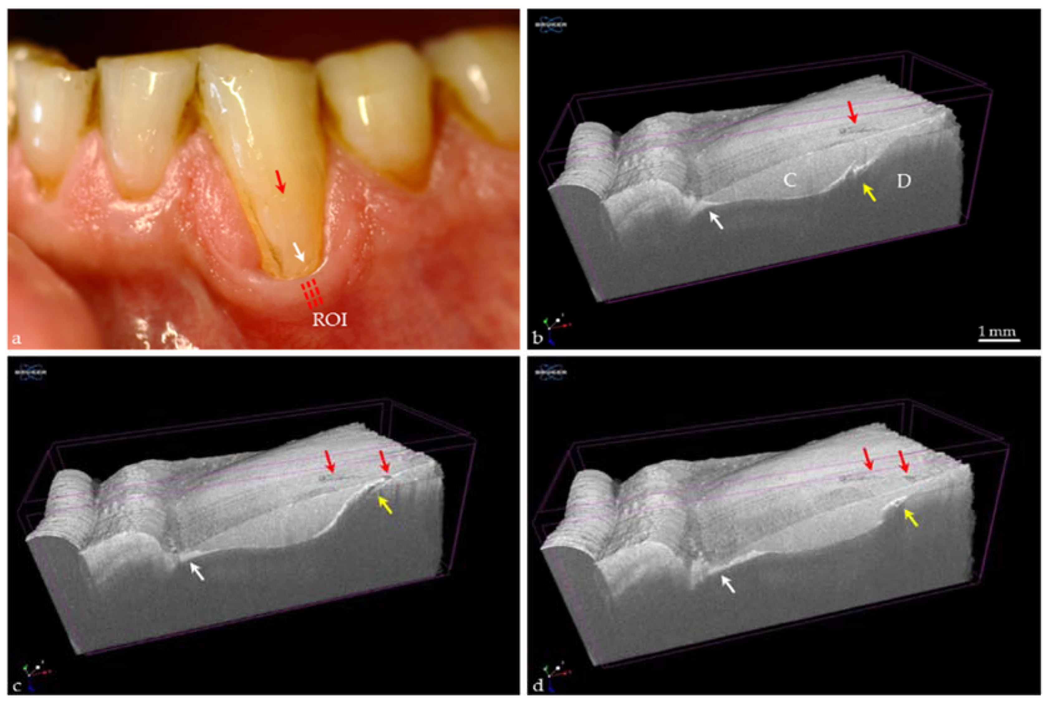
3.2. Erosive Tooth Wear

Within the oral cavity, demineralization and remineralization of tooth surfaces (enamel, dentin) are in a state of equilibrium. Even without the participation of bacteria (caries) in a multifactorial process, a shift in the balance can occur towards demineralization, which is caused by different patient-related and nutritional factors, e.g., eating/drinking habits, oral hygiene, medication and saliva conditions. The destructive effect of acid-induced tissue loss of tooth surface and subsurface regions is known as dental erosion (erosive tooth wear) [50].
Clinical diagnosis indices for recording the erosive wear include morphological as well as quantitative criteria, particularly the Basic Erosive Wear Examination (BEWE) [51]. However, the validity of diagnostic criteria and grading/scoring are unsatisfactory or unclear. Thus, there is a need to develop practicable and preferably chairside diagnostic tools [51]. Different assessment methods have been applied for in vitro and in vivo studies to evaluate erosive tooth wear, e.g., profilometry, measuring microscopy techniques, TMR, SEM, atomic force microscopy, nano- and micro-hardness tests, and the iodide permeability test, as well as methods which chemically analyze minerals dissolved from dental hard tissue [52]. In this context, OCT has been described as a suitable tool for the investigation of early erosions of unaffected surfaces [52].
OCT allows the assessment of the mineralization degree of enamel or dentin and the visualization of very early demineralizations, and thus permits early erosive lesions to be characterized [52]. Until now, erosion could only be assessed clinically through long-term observations of the loss of hard tooth tissue over months to years, well after the erosion has been initiated. With OCT, incipient erosion without loss of enamel height could be recognized and a therapeutic remineralization process could be monitored and assessed [8]. Figure 13 shows an initial enamel erosion before the thickness of hard tissue had changed, and its partial repair. The erosion was produced by the soft drink Coca Cola [53,54]. The method can visualize the partial reversal of demineralization using artificial saliva and “effects”, which clearly took place within covered and uncovered areas of the enamel surface. It is clear that the surface area of the partially protected enamel was repaired to a higher degree by artificial saliva.

3.3. Caries Therapy

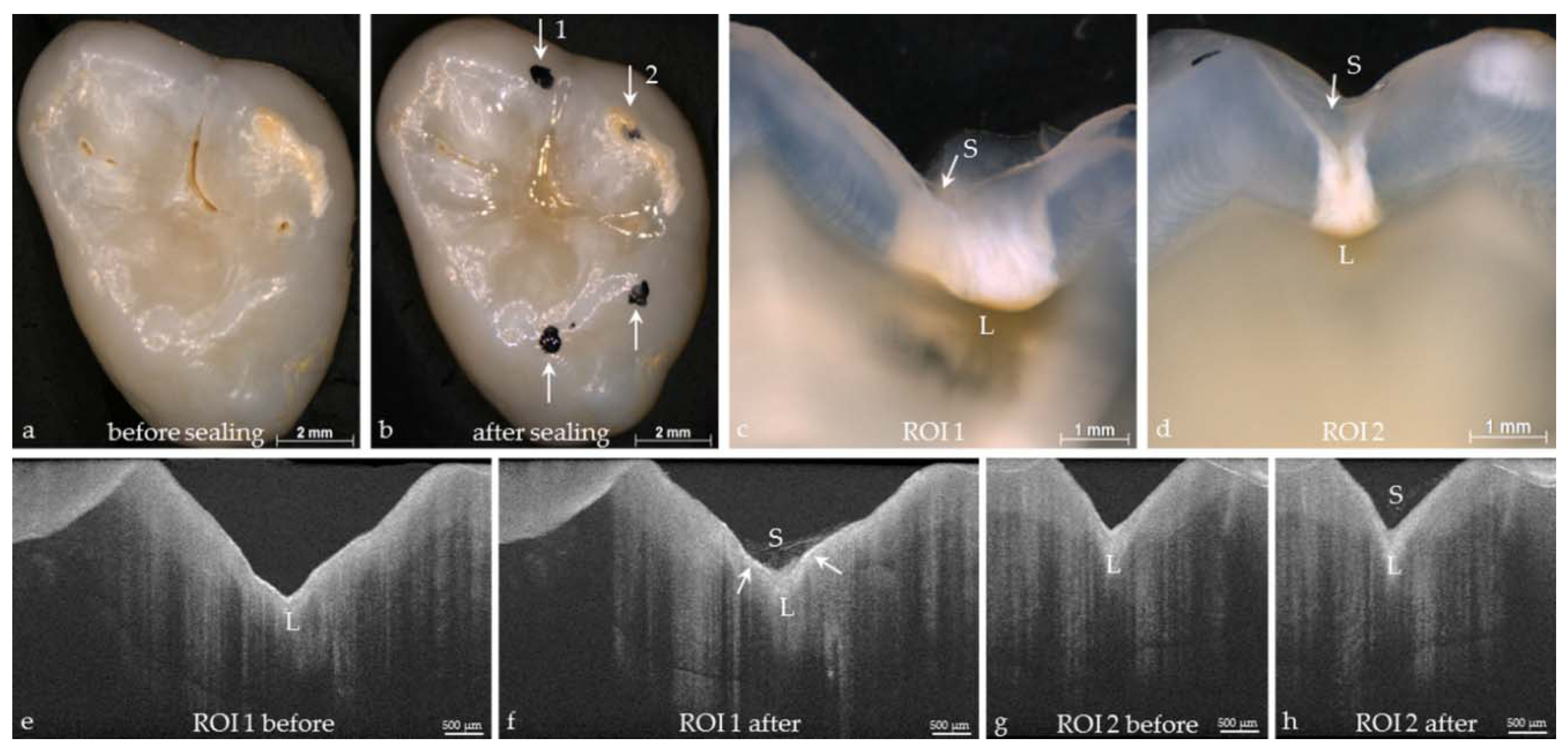
3.3.1. Assessment of Pit and Fissure Sealing

A major focus of prevention is on pit and fissure sealing as one measure to prevent early caries initiation and progression in occlusal surfaces [40]. In cross-sectional OCT images, fissure depth and caries lesions can be detected due to increased backscattering of light. After sealant application, images reveal its penetration into fissures and its adaptation to the tooth surface (Figure 14). Incompletely filled zones or bubbles can be detected and monitoring over time is possible. Strong reflections at the enamel surface can hamper the detection of caries lesions by covering the light backscattered from lesions. Using polarization-sensitive optical coherence tomography, the contrast can be enhanced by minimizing this effect [55].

3.3.2. Remaining Dentin during Caries Removal

Opening the pulp chamber during caries removal of deep lesions or tooth preparation is a major risk in the maintenance of the pulp vitality and the tooth, and should therefore be avoided. However, during the treatment of dentin areas close to the pulp, an iatrogenic opening of the pulp complex is sometimes difficult to prevent due to the unknown and invisible location of the pulp chamber.
In contrast to an introduced indirect measuring method based on the determination of the electrical resistance of the residual dentin (prepometer™, Hager and Werken, Duisburg, Germany), the OCT offers great potential for imaging the outline of the pulp chamber. The remaining dentin thickness and pulp geometry, e.g., pulp horns, can be visualized in vitro during dental procedures using optical coherence tomography [56,57,58,59]. We found that the roof of the pulp chamber could be displayed using SD-OCT at a mean distance through dentin of 850 µm, whereas the minimum remaining dentin thickness which could be imaged was 45 µm (Figure 15), and is in accordance with Fonseca et al. [57]. Therefore, the OCT technique could be a valuable diagnostic tool during dental treatment and help prevent accidental pulp exposures by estimating the remaining dentin thickness.

3.3.3. Composite Restorations

Today, the adhesive bonding of composite materials to enamel and dentin is the predominant restoration technique. The concept is based on both a durable micro retentive and a chemical bond between composite, adhesive and tooth to obtain restorations, which are free of interfacial adhesive defects. As composites shrink during polymerization, the adhesive technique is the crucial prerequisite for minimally invasive treatment. Conversely, this means that the adhesive failure of the bond can be considered as a parameter to assess the quality of restorations [60] (Figure 16).
The morphological correlate for this is the formation of interfacial gaps, or so-called adhesive defects. For the evaluation of composite restorations, clinical trials are still the gold standard, with clinical success assessed by functional, biological, and esthetic criteria [15,61]. Clinically interfacial adhesive defects can only be detected at restoration margins. According to FDI (Fédération Dentaire Internationale) [15], marginal gaps of score 2 (50 µm width) are to be removed by polishing. Gaps of score 3 (50–150 µm), cannot be removed by polishing but are to be monitored. Restorations with marginal gaps of score 4 (width > 250 µm) must be repaired or replaced if these are loose (score 5). However, statements on the clinical performance of a restoration system are possible after the passage of at least three years [61,62,63]. Furthermore, clinical studies have additional disadvantages, for instance, personnel and financial expenses are relatively high and the filling systems are often no longer on the market at the conclusion of clinical trials after 3–5 years. Consequently, early experimental evaluation of adhesive systems and composites is desirable and a prerequisite for further developing restoration systems. It is also desirable to formulate clear statements regarding the quality of the adhesive bond and the long-term prognosis of restorations immediately after restoration placement, or at early follow-up. On this matter, OCT could provide relevant information. The method enables high-resolution real-time images to be made of composite restorations in 2D and 3D in vitro, ex vivo and in vivo, up to an imaging depth of 2.5 mm. The homogeneity of different restoration materials can be checked, as well as interfacial adhesive defects. Especially the clinically relevant integrity of enamel- and dentin-restoration margins can be reliably evaluated, including (at least partially) the situation beneath the gingiva, as well as the seal quality at these locations (Figure 17). The validity and reproducibility of the method has been demonstrated [64,65].

Quality Control Using OCT

Thanks to the fast processing of highly resolved images and its non-invasive and harmless approach, OCT has great potential for time-resolved visualization of fast processes [9]. This is also the case in the fields of learning and teaching, and consequently in quality or process control and in monitoring therapy outcomes. The technique allows many opportunities for self-checking. Individual work steps during restoration placement can be demonstrated, better understood and single procedural errors and resulting failures can be clearly seen. This results in great potential in supporting the development of dental materials, and to teach and learn therapeutic procedures (Figure 18 and Figure 19).

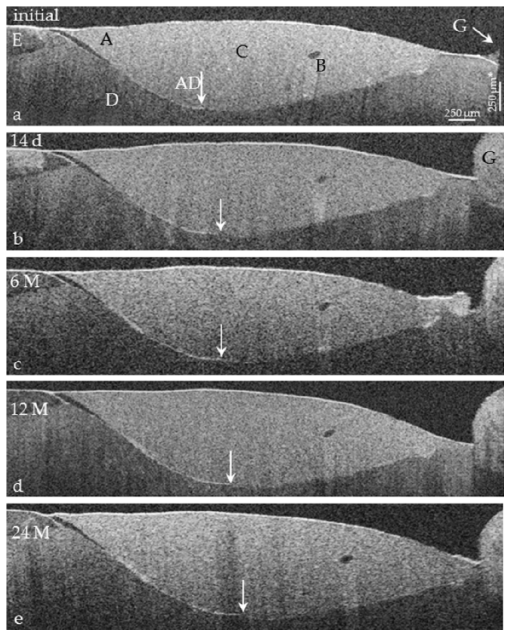
Monitoring of Composite Restorations

As OCT is non-invasive, it inevitably follows that it offers the possibility of monitoring the bond failure at the same composite restorations in the same cross-sectional images at any time. In long-term clinical studies conducted by the authors, composite restorations will be imaged parallel to clinical assessment using SD-OCT (vestibular areas, Class V, Figure 4c). In a B-scan by measurement the lengths of adhesive failure and interface the proportion (%) of the interfacial adhesive failure can be calculated separately for enamel, dentin or cement. In 25 equidistantly distributed B-scans of an image stack the mean values of a restoration result with regard to enamel, dentin or cement. From these the values per group can be calculated over the entire period of study. The results of the clinical studies will reveal whether OCT can be an early, cost-effective, and time-saving tool for evaluating the performance of adhesives or composite restoration systems in vivo. In vitro and ex vivo, an exceptional methodological advantage is that identical cross-sectional images will be assessed and compared before and after artificial aging. This results in pairs of measured values. In this case the variance between specimens can be excluded and just the variance within the specimens remains. Compared with unpaired values, at identical ratings of statistical power the number of specimens can be reduced.
The quality assessment of composite restorations is based on the evaluation of functional, biological, and esthetic criteria [61]. It is also recognized that restoration margins should be sealed or intact. The question of what degree of interfacial bond failure is “clinically acceptable” is still open for discussion. From this point of view, we believe that development over time for each individual case must be a focus of consideration as interfacial gap is not just like another. To date, nobody has reliably assessed and estimated these individual dynamics under clinical conditions.
Figure 20 and Figure 21 demonstrate two specific cases of gap formation between composite restoration and tooth during clinical function. Figure 20a–c show a rapid increase of bond failure at dentin over a short period of six months, while the composite-enamel bond has proven itself. In contrast, a much slower dynamic of gap progression over the longer period of 24 months is seen in Figure 21a–e. There are no signs of caries at the defective restoration margins (secondary caries). Figure 22 and Figure 23 provide an example of partial restoration loss in images and the percentage of interfacial gap formation. Within the limits of the method, the concept of restoration monitoring using OCT can be transferred onto other restoration materials.

4. Conclusions

As a non-invasive imaging technique, optical coherence tomography opens up enormous potential for its application in more effective and reproducible diagnosis and therapy of caries. Caries lesions can be detected significantly earlier and the progress of early dental caries and the effectiveness of restorative treatment options could be monitored longitudinally. This explorative technique could provide additional clinically relevant information, is fast, and thus suitable and cost-effective to use in research. In clinical practice it could be applied equally well if appropriate equipment becomes available.

Acknowledgments

This work was supported by the European Regional Development Fund (ERDF, 100175024; 100175035) and by the German Research Foundation (DFG)/the Saxon State Ministry for Science and the Arts (SMWK) (376/7-1 FUG). We acknowledge support from the German Research Foundation (DFG) and Universität Leipzig within the program of Open Access Publishing. We would like to thank Thorlabs GmbH, Dachau, Germany for provision of the SS-OCT equipment and Timothy Jones (IALT, University of Leipzig, Germany) for editorial assistance.

Author Contributions

Hartmut Schneider and Rainer Haak conceived the ideas. Hartmut Schneider, Kyung-Jin Park, Matthias Häfer, Felix Krause and Rainer Haak designed the experiments. Hartmut Schneider, Kyung-Jin Park, Matthias Häfer, Claudia Rüger, Gerhard Schmalz and Jana Schmidt performed the experiments. Hartmut Schneider, Kyung-Jin Park, Matthias Häfer, Claudia Rüger, Gerhard Schmalz, Felix Krause, Jana Schmidt, Dirk Ziebolz and Rainer Haak processed the data. Kyung-Jin Park, Matthias Häfer, Claudia Rüger, Gerhard Schmalz, Felix Krause, Jana Schmidt contributed with the materials and samples. Hartmut Schneider, Felix Krause, Dirk Ziebolz and Rainer Haak wrote the paper.

Conflict of Interest

The authors declare no conflict of interest. The founding sponsors had no role in the design of the studies; in the collection, analyses, or interpretation of data; in the writing of the manuscript, and in the decision to publish the results.

References

  1. Brouwer, F.; Askar, H.; Paris, S.; Schwendicke, F. Detecting Secondary Caries Lesions: A Systematic Review and Meta-analysis. J. Dent. Res. 2016, 95, 143–151. [Google Scholar] [CrossRef] [PubMed]
  2. Schwendicke, F.; Brouwer, F.; Paris, S.; Stolpe, M. Detecting Proximal Secondary Caries Lesions: A Cost-effectiveness Analysis. J. Dent. Res. 2016, 95, 152–159. [Google Scholar] [CrossRef] [PubMed]
  3. Ismail, A.I. The International Caries Detection and Assessment System (ICDAS II). Available online: https://www.icdas.org/uploads/Rationale%20and%20Evidence%20ICDAS%20II%20September%2011-1.pdf (accessed on 12 January 2017).
  4. Ismail, A.I.; Sohn, W.; Tellez, M.; Amaya, A.; Sen, A.; Hasson, H.; Pitts, N.B. The International Caries Detection and Assessment System (ICDAS): An integrated system for measuring dental caries. Community Dent. Oral Epidemiol. 2007, 35, 170–178. [Google Scholar] [CrossRef] [PubMed]
  5. Diniz, M.B.; Rodrigues, J.A.; Hug, I.; Cordeiro, R.d.C.L.; Lussi, A. Reproducibility and accuracy of the ICDAS-II for occlusal caries detection. Community Dent. Oral Epidemiol. 2009, 37, 399–404. [Google Scholar] [CrossRef] [PubMed]
  6. Deligeorgi, V.; Mjör, I.A.; Wilson, N.H.H. An Overview of and Replacement Reasons for the of Restorations Placement. Prim. Dent. Care 2001, 8, 5–11. [Google Scholar] [CrossRef] [PubMed]
  7. Abdullah, Z.; John, J. Minimally Invasive Treatment of White Spot Lesions-A Systematic Review. Oral Health Prev. Dent. 2016, 14, 197–205. [Google Scholar] [PubMed]
  8. Mandurah, M.M.; Sadr, A.; Shimada, Y.; Kitasako, Y.; Nakashima, S.; Bakhsh, T.A.; Tagami, J.; Sumi, Y. Monitoring remineralization of enamel subsurface lesions by optical coherence tomography. J. Biomed. Opt. 2013, 18, 46006. [Google Scholar] [CrossRef] [PubMed]
  9. Schneider, H.; Park, K.-J.; Rueger, C.; Ziebolz, D.; Krause, F.; Haak, R. Imaging resin infiltration into non-cavitated carious lesions by optical coherence tomography. J. Dent. 2017. [Google Scholar] [CrossRef] [PubMed]
  10. Douglas, S.M.; Fried, D.; Darling, C.L. Imaging Natural Occlusal Caries Lesions with Optical Coherence Tomography. Proc. SPIE. Int. Soc. Opt. Eng. 2010, 7549, 75490N. [Google Scholar] [PubMed]
  11. Alammari, M.R.; Smith, P.W.; de Jong, E.D.J.; Higham, S.M. Quantitative light-induced fluorescence (QLF): A tool for early occlusal dental caries detection and supporting decision making in vivo. J. Dent. 2013, 41, 127–132. [Google Scholar] [CrossRef] [PubMed]
  12. Pretty, I.A. Caries detection and diagnosis: Novel technologies. J. Dent. 2006, 34, 727–739. [Google Scholar] [CrossRef] [PubMed]
  13. Gimenez, T.; Piovesan, C.; Braga, M.M.; Raggio, D.P.; Deery, C.; Ricketts, D.N.; Ekstrand, K.R.; Mendes, F.M. Visual Inspection for Caries Detection: A Systematic Review and Meta-analysis. J. Dent. Res. 2015, 94, 895–904. [Google Scholar] [CrossRef] [PubMed]
  14. Swets, J. Measuring the accuracy of diagnostic systems. Science 1988, 240, 1285–1293. [Google Scholar] [CrossRef] [PubMed]
  15. Hickel, R.; Peschke, A.; Tyas, M.; Mjor, I.; Bayne, S.; Peters, M.; Hiller, K.-A.; Randall, R.; Vanherle, G.; Heintze, S.D. FDI World Dental Federation—Clinical criteria for the evaluation of direct and indirect restorations. Update and clinical examples. J. Adhes. Dent. 2010, 12, 259–272. [Google Scholar] [CrossRef] [PubMed]
  16. American Dental Association. American Dental Association acceptance program guidelines: Composite resins for posterior restorations. JADA 2003, 134, 510–512. [Google Scholar]
  17. Roulet, J.F.; Reich, T.; Blunck, U.; Noack, M. Quantitative margin analysis in the scanning electron microscope. Scanning Microsc. 1989, 3, 147–159. [Google Scholar] [PubMed]
  18. Huang, D.; Swanson, E.A.; Lin, C.P.; Schuman, J.S.; Stinson, W.G.; Chang, W.; Hee, M.R.; Flotte, T.; Gregory, K.; Puliafito, C.A.; et al. Optical Coherence Tomography. Science 1991, 22, 1178–1181. [Google Scholar] [CrossRef]
  19. Wylegala, A.; Teper, S.; Dobrowolski, D.; Wylegala, E. Optical coherence angiography: A review. Medicine 2016, 95, e4907. [Google Scholar] [CrossRef] [PubMed]
  20. Adhi, M.; Duker, J.S. Optical coherence tomography--current and future applications. Curr. Opin. Ophthalmol. 2013, 24, 213–221. [Google Scholar] [CrossRef] [PubMed]
  21. Hangai, M.; Ojima, Y.; Gotoh, N.; Inoue, R.; Yasuno, Y.; Makita, S.; Yamanari, M.; Yatagai, T.; Kita, M.; Yoshimura, N. Three-dimensional imaging of macular holes with high-speed optical coherence tomography. Ophthalmology 2007, 114, 763–773. [Google Scholar] [CrossRef] [PubMed]
  22. Bernardes, R.; Cunha-Vaz, J. Optical Coherence Tomography: A Clinical and Technical Update; Springer: Berlin/Heidelberg, Germany, 2012. [Google Scholar]
  23. Ulrich, M. Optical coherence tomography for diagnosis of basal cell carcinoma: Essentials and perspectives. Br. J. Dermatol. 2016, 175, 1145–1146. [Google Scholar] [CrossRef] [PubMed]
  24. Cheng, H.M.; Lo, S.; Scolyer, R.; Meekings, A.; Carlos, G.; Guitera, P. Accuracy of optical coherence tomography for the diagnosis of superficial basal cell carcinoma: A prospective, consecutive, cohort study of 168 cases. Br. J. Dermatol. 2016, 175, 1290–1300. [Google Scholar] [CrossRef] [PubMed]
  25. Vignali, L.; Solinas, E.; Emanuele, E. Research and Clinical Applications of Optical Coherence Tomography in Invasive Cardiology: A Review. Curr. Cardiol. Rev. 2014, 10, 369–376. [Google Scholar] [CrossRef] [PubMed]
  26. Colston, B.; Sathyam, U.; Dasilva, L.; Everett, M.; Stroeve, P.; Otis, L. Dental OCT. Opt. Express 1998, 14, 230–238. [Google Scholar] [CrossRef]
  27. Colston, B.W.; Everett, M.; Sathyam, U.S.; Dasilva, L.; Otis, L.L. Imaging of the oral cavity using optical coherence tomography. Monogr. Oral. Sci. 2000, 17, 32–55. [Google Scholar] [PubMed]
  28. Feldchtein, F.I.; Gelikonov, G.V.; Gelikonov, V.M.; Iksanov, R.R.; Kuranov, R.V.; Sergeev, A.M.; Gladkova, N.D.; Ourutina, M.N.; Warren, J.A.; Reitze, D.H. In vivo OCT imaging of hard and soft tissue of the oral cavity. Opt. Express 1998, 3, 239–250. [Google Scholar] [CrossRef] [PubMed]
  29. Shimada, Y.; Sadr, A.; Sumi, Y.; Tagami, J. Application of Optical Coherence Tomography (OCT) for Diagnosis of Caries, Cracks, and Defects of Restorations. Curr. Oral Health Rep. 2015, 2, 73–80. [Google Scholar] [CrossRef] [PubMed]
  30. Min, J.H.; Inaba, D.; Kwon, H.K.; Chung, J.H.; Kim, B.I. Evaluation of penetration effect of resin infiltrant using optical coherence tomography. J. Dent. 2015, 43, 720–725. [Google Scholar] [CrossRef] [PubMed]
  31. Drexler, W.; Liu, M.; Kumar, A.; Kamali, T.; Unterhuber, A.; Leitgeb, R.A. Optical coherence tomography today: Speed, contrast, and multimodality. J. Biomed. Opt. 2014, 19, 71412. [Google Scholar] [CrossRef] [PubMed]
  32. Hsieh, Y.-S.; Ho, Y.-C.; Lee, S.-Y.; Chuang, C.-C.; Tsai, J.-C.; Lin, K.-F.; Sun, C.-W. Dental optical coherence tomography. Sensors 2013, 13, 8928–8949. [Google Scholar] [CrossRef] [PubMed]
  33. Wijesinghe, R.E.; Cho, N.H.; Park, K.; Jeon, M.; Kim, J. Bio-Photonic Detection and Quantitative Evaluation Method for the Progression of Dental Caries Using Optical Frequency-Domain Imaging Method. Sensors 2016, 16. [Google Scholar] [CrossRef] [PubMed]
  34. Wu, T.; Wang, Q.; Liu, Y.; Wang, J.; He, C.; Gu, X. Extending the Effective Ranging Depth of Spectral Domain Optical Coherence Tomography by Spatial Frequency Domain Multiplexing. Appl. Sci. 2016, 6, 360. [Google Scholar] [CrossRef]
  35. Nakagawa, H.; Sadr, A.; Shimada, Y.; Tagami, J.; Sumi, Y. Validation of swept source optical coherence tomography (SS-OCT) for the diagnosis of smooth surface caries in vitro. J. Dent. 2013, 41, 80–89. [Google Scholar] [CrossRef] [PubMed]
  36. Ishida, S.; Nishizawa, N. Quantitative comparison of contrast and imaging depth of ultrahigh-resolution optical coherence tomography images in 800–1700 nm wavelength region. Biomed. Opt. Express 2012, 3, 282–294. [Google Scholar] [CrossRef] [PubMed]
  37. Sharma, U.; Chang, E.W.; Yun, S.H. Long-wavelength optical coherence tomography at 17 μm for enhanced imaging depth. Opt. Express 2008, 16, 19712. [Google Scholar] [CrossRef] [PubMed]
  38. Kodach, V.M.; Kalkman, J.; Faber, D.J.; van Leeuwen, T.G. Quantitative comparison of the OCT imaging depth at 1300 nm and 1600 nm. Biomed. Opt. Express 2010, 1, 176–185. [Google Scholar] [CrossRef] [PubMed]
  39. Darling, C.L.; Huynh, G.D.; Fried, D. Light scattering properties of natural and artificially demineralized dental enamel at 1310 nm. J. Biomed. Opt. 2006, 11, 34023. [Google Scholar] [CrossRef] [PubMed]
  40. Ito, S.; Shimada, Y.; Sadr, A.; Nakajima, Y.; Miyashin, M.; Tagami, J.; Sumi, Y. Assessment of occlusal fissure depth and sealant penetration using optical coherence tomography. Dent. Mater. J. 2016, 35, 432–439. [Google Scholar] [CrossRef] [PubMed]
  41. Srivastava, K.; Tikku, T.; Khanna, R.; Sachan, K. Risk factors and management of white spot lesions in orthodontics. J. Orthod. Sci. 2013, 2, 43–49. [Google Scholar] [CrossRef] [PubMed]
  42. Shimada, Y.; Sadr, A.; Burrow, M.F.; Tagami, J.; Ozawa, N.; Sumi, Y. Validation of swept-source optical coherence tomography (SS-OCT) for the diagnosis of occlusal caries. J. Dent. 2010, 38, 655–665. [Google Scholar] [CrossRef] [PubMed]
  43. Schneider, H.; Gottwald, R.; Meißner, T.; Krause, F.; Becker, K.; Attin, T.; Haak, R. Assessment of uncavitated carious enamel lesions by optical coherence tomography and X-ray microtomography. Caries Res. 2016, 50, 239–240. [Google Scholar]
  44. Shimada, Y.; Nakagawa, H.; Sadr, A.; Wada, I.; Nakajima, M.; Nikaido, T.; Otsuki, M.; Tagami, J.; Sumi, Y. Noninvasive cross-sectional imaging of proximal caries using swept-source optical coherence tomography (SS-OCT) in vivo. J. Biophotonics 2014, 7, 506–513. [Google Scholar] [CrossRef] [PubMed]
  45. Fried, D.; Xie, J.; Shafi, S.; Featherstone, J.D.B.; Breunig, T.M.; Le, C. Imaging caries lesions and lesion progression with polarization sensitive optical coherence tomography. J. Biomed. Opt. 2002, 7, 618–627. [Google Scholar] [CrossRef] [PubMed]
  46. Kang, H.; Darling, C.L.; Fried, D. Enhancing the detection of hidden occlusal caries lesions with OCT using high index liquids. Proc. SPIE Int. Soc. Opt. Eng. 2014, 8929, 89290O. [Google Scholar] [PubMed]
  47. Volgenant, C.M.C.; Fernandez Y Mostajo, M.; Rosema, N.A.M.; van der Weijden, F.A.; Cate, J.M.; van der Veen, M.H. Comparison of red autofluorescing plaque and disclosed plaque-a cross-sectional study. Clin. Oral Investig. 2016, 20, 2551–2558. [Google Scholar] [CrossRef] [PubMed]
  48. Karlsson, L. Caries Detection Methods Based on Changes in Optical Properties between Healthy and Carious Tissue. Int. J. Dent. 2010. [Google Scholar] [CrossRef] [PubMed]
  49. Timoshchuk, M.-A.I.; Ridge, J.S.; Rugg, A.L.; Nelson, L.Y.; Kim, A.S.; Seibel, E.J. Real-Time Porphyrin Detection in Plaque and Caries: A Case Study. Proc. SPIE 2015. [Google Scholar] [CrossRef]
  50. Lussi, A.; Carvalho, T.S. Erosive tooth wear: A multifactorial condition of growing concern and increasing knowledge. Monogr. Oral Sci. 2014, 25, 1–15. [Google Scholar] [PubMed]
  51. Ganss, C.; Lussi, A. Diagnosis of erosive tooth wear. Monogr. Oral Sci. 2014, 25, 22–31. [Google Scholar] [PubMed]
  52. Attin, T.; Wegehaupt, F.J. Methods for assessment of dental erosion. Monogr. Oral Sci. 2014, 25, 123–142. [Google Scholar] [PubMed]
  53. Poggio, C.; Lombardini, M.; Colombo, M.; Bianchi, S. Impact of two toothpastes on repairing enamel erosion produced by a soft drink: An AFM in vitro study. J. Dent. 2010, 38, 868–874. [Google Scholar] [CrossRef] [PubMed]
  54. Carvalho Sales-Peres, S.H.; Magalhães, A.C.; Andrade Moreira Machado, M.A.; Buzalaf, M.A.R. Evaluation of The Erosive Potential of Soft Drinks. Eur. J. Dent. 2007, 1, 10–13. [Google Scholar] [PubMed]
  55. Jones, R.S.; Staninec, M.; Fried, D. Imaging artificial caries under composite sealants and restorations. J. Biomed. Opt. 2004, 9, 1297–1304. [Google Scholar] [CrossRef] [PubMed]
  56. Majkut, P.; Sadr, A.; Shimada, Y.; Sumi, Y.; Tagami, J. Validation of Optical Coherence Tomography against Micro-computed Tomography for Evaluation of Remaining Coronal Dentin Thickness. J. Endod. 2015, 41, 1349–1352. [Google Scholar] [CrossRef] [PubMed]
  57. Fonsêca, D.D.D.; Kyotoku, B.B.C.; Maia, A.M.A.; Gomes, A.S.L. In vitro imaging of remaining dentin and pulp chamber by optical coherence tomography: Comparison between 850 and 1280 nm. J. Biomed. Opt. 2009, 14, 24009. [Google Scholar] [CrossRef] [PubMed]
  58. Fujita, R.; Komada, W.; Nozaki, K.; Miura, H. Measurement of the remaining dentin thickness using optical coherence tomography for crown preparation. Dent. Mater. 2014, 33, 355–362. [Google Scholar] [CrossRef]
  59. Sinescu, C.; Negrutiu, M.L.; Bradu, A.; Duma, V.-F.; Podoleanu, A.G. Noninvasive Quantitative Evaluation of the Dentin Layer during Dental Procedures Using Optical Coherence Tomography. Comput. Math. Methods Med. 2015. [Google Scholar] [CrossRef] [PubMed]
  60. Heintze, S.D. Clinical relevance of tests on bond strength, microleakage and marginal adaptation. Dent. Mater. 2013, 29, 59–84. [Google Scholar] [CrossRef] [PubMed]
  61. Hickel, R.; Roulet, J.-F.; Bayne, S.; Heintze, S.D.; Mjor, I.A.; Peters, M.; Rousson, V.; Randall, R.; Schmalz, G.; Tyas, M.; et al. Recommendations for conducting controlled clinical studies of dental restorative materials. Clin. Oral Investig. 2007, 11, 5–33. [Google Scholar] [CrossRef] [PubMed]
  62. Häfer, M.; Jentsch, H.; Haak, R.; Schneider, H. A three-year clinical evaluation of a one-step self-etch and a two-step etch-and-rinse adhesive in non-carious cervical lesions. J. Dent. 2015, 43, 350–361. [Google Scholar] [CrossRef] [PubMed]
  63. Häfer, M.; Schneider, H.; Rupf, S.; Busch, I.; Fuchß, A.; Merte, I.; Jentsch, H.; Haak, R.; Merte, K. Experimental and clinical evaluation of a self-etching and an etch-and-rinse adhesive system. J. Adhes. Dent. 2013, 15, 275–286. [Google Scholar] [PubMed]
  64. Park, K.-J.; Schneider, H.; Haak, R. Assessment of defects at tooth/self-adhering flowable composite interface using swept-source optical coherence tomography (SS-OCT). Dent. Mater. 2015, 31, 534–541. [Google Scholar] [CrossRef] [PubMed]
  65. Park, K.J.; Schneider, H.; Haak, R. Assessment of interfacial defects at composite restorations by swept source optical coherence tomography. J. Biomed. Opt. 2013, 18. [Google Scholar] [CrossRef] [PubMed]
Figure 1. Conformance of visual assessment with optical coherence tomography. (a) Extracted human premolar with a carious lesion (L) of International Caries Detection and Assessment System (ICDAS II) Code 1. The lesion is visually detectable only after drying. Marks define the region of interest (ROI); (b) In the cross-sectional image of the ROI, generated using spectral domain OCT, bright shadowed spots reveal the lesion area is limited to the first half of the enamel (E); (c) After sectioning, demineralization can be imaged using dark-field light microscopy (DFLM) corresponding to the lesion details in the OCT image. D: dentin, EDJ: enamel-dentin junction.
Applsci 07 00472 g001
Figure 2. Screenshot, in vivo image of a human incisor. Partial conformance of visual assessment with OCT. A carious lesion (L) of ICDAS II Code 2 can be detected visually at the air-dried enamel surface (red arrow). In the SD-OCT B-scan, this lesion appears as a bright shadowed area without cavitation. Compared to visual assessment, the OCT signal reveals an extended lesion body with dentin (D) involvement and a mineral-rich and porous surface layer (*). In addition, defects, or cracks in the enamel (E) are seen to cause shadowing (white arrows). G: gingiva, EDJ: enamel-dentin junction.
Applsci 07 00472 g002
Figure 3. SD-OCT imaging (2D, 3D) of an extracted human premolar restored with composite (C). FOV: field of view, E: enamel, D: dentin, EDJ: enamel-dentin junction.
Applsci 07 00472 g003
Figure 4. (a) SD-OCT Telesto SP II; and (b) SSOCT OCS1300SS; (c) In vivo imaging of vestibular smooth surfaces of incisors, canines and premolars with the handheld and mechanically stabilized scanning probe (P).
Applsci 07 00472 g004
Figure 5. (a) Extracted human molar. A carious lesion (ICDAS-II Code 2) without cavitation, but with involvement of dentin (D); (bd) Using different positions or angles, SS-OCT cross-sectional images reveal bright areas (signals) indicating the extension of the lesion (white arrows) and to detect further tissue destructions like enamel cracks ((e), red arrows, *), which are primarily invisible in light microscopy. EDJ: enamel–dentin junction.
Applsci 07 00472 g005
Figure 6. Extracted human premolar with a carious lesion (L) of ICDAS II Code 1. (a) ROI; (b) The demineralization within the ROI (white arrow) is equally imaged by dark-field light microscopy (DFLM); (c) spinning-disc confocal microscopy (SDCM); (d) X-ray microtomography (µCT); as well as (e) SD-OCT. E: enamel, D: dentin, EDJ: enamel-dentin-junction.
Applsci 07 00472 g006
Figure 7. (a) Extracted human molar with occlusal caries (ICDAS II Code 2); (b) In the histological section through ROI, lesions (white arrows) and enamel cracks (yellow arrows) appear; (c) In the conventional digital radiograph no defects or lesions are visible; (d) Bright signals in the OCT image of the ROI demonstrate caries lesions (white arrows) and enamel cracking (yellow arrow). E: enamel; D: dentin.
Applsci 07 00472 g007
Figure 8. Extracted human molar with occlusal carious lesions without cavitation (L, arrow). (a) µCT image of a ROI as reference; (b) Bright signals show extended lesion areas (arrows); (c) The varying of the OCT probe angle provides increased OCT signals and additional information about dentin involvement.
Applsci 07 00472 g008
Figure 9. Extracted human molar with occlusal carious lesions without cavitation (L). (a) µCT image of ROI. After application of glycerin gel signal-to-noise ratio in the SD-OCT cross-sectional image (c) can be improved towards the image (b) (without glycerine, white arrows) leading to an adequate conformance of µCT with OCT.
Applsci 07 00472 g009
Figure 10. Extracted human canine. There is no conformance of visual assessment with OCT. Visual inspection of the dry smooth surface does not reveal signs of an early-stage carious lesion (L). In contrast, the 3D SD-OCT cross-sectional image of the ROI showed a distinct bright area (L) within the first quarter of enamel (E) with a shadow underneath. The lesion can be confirmed using light microscopy (LM). The A-scan of the position marked in the OCT-image shows the depth profile of the demineralized zone in the enamel surface (A-Scan average 5, additional signal median averaging 6). * grey scale between demineralized and healthy region.
Applsci 07 00472 g010
Figure 11. Extracted human premolar with early proximal demineralizations. There is a partial match of the visual and OCT assessment. (a) Hardly visible on wet enamel, the early demineralization (1) could also be seen on the dry surface (b); (cf) SD-OCT reveals a clinically invisible demineralization in the outer enamel zone (*); (c,d) The OCT images reveal a bright signal in position 1 (L, shadow); (e) The OCT of the wet surface shows an early demineralization in position 2 of image (b); (f) After air drying, an additional signal arises in position 3. Visually both lesions are invisible (a,b). With the knowledge of the OCT images, at points 2 and 3, slight opacities could also be anticipated on the images (a,b). The A-scans (average 5) of the marked positions 1 and 2 in the OCT-images demonstrate the depth profiles of the demineralized zones of the enamel surface. Δ grey scales between demineralized and healthy region.
Applsci 07 00472 g011
Figure 12. Canine tooth in vivo. (a) A cervical composite restoration (C) shows a margin discoloration (white arrow); (b,c) In the 3D and 2D OCT images, a margin gap with ingress of material is detected (red arrows). At dentin (D), an extensive interfacial gap has formed (white arrows); (d) Using quantitative light-induced fluorescence the image showed red fluorescence (red arrow) at the cervical restoration margin indicating bacterial activity by porphyrin invasion into the gap. There are no signs of “secondary caries” at the restoration margin, but the stability of the situation requires observation over time (monitoring).
Applsci 07 00472 g012
Figure 13. Extracted human incisor. (a) Starting situation. The SD-OCT shows a small bright band in the enamel surface (E), which could represent a lower mineralized zone (white asterisks). The yellow double-headed arrow indicates the surface area, which was covered by composite to prevent demineralization of the enamel; (b) After 5 min exposure of enamel to Coca Cola (37 °C) a broader bright area (red asterisks) can already clearly be distinguished, which represents a zone of erosion that also extended below the composite coating; (c) After 30 min of exposure, the demineralization has made further progress, which is indicated by the reduced contrast at the enamel-dentin junction (EDJ, red arrow) or its disappearance (white arrow); (d) After removal of the composite coating the tooth was stored in artificial saliva. Within 60 min, the bright demineralized area previously covered by composite (dotted double-headed arrow) completely disappeared indicating a process of repair (“remineralization”). In uncovered areas, the EDJ appears in a higher contrast compared to (c) and is more extended (green arrow). Particularly in the incisal area, the erosion is clearly reduced (**) compared to (b,c).
Applsci 07 00472 g013
Figure 14. (a) Extracted human molar before; and (b) after fissure sealing with Helioseal. (c,d) In cross-sections through ROI 1 and 2 occlusal caries beneath the sealer can be identified (L). Using SD-OCT, carious lesions (L, shadow) can be localized (e,g) before; and (f,h) after sealing. The sealer (S) has penetrated into the fissures, is inhomogeneously distributed and adapted to the enamel surface with (f, white arrows) or (h) without interfacial gap; (f) The bright signals reveal an interfacial gap (white arrows) between sealant and enamel. Monitoring will reveal changes over time.
Applsci 07 00472 g014
Figure 15. Extracted human molars trimmed and cross-sectioned longitudinally through pulp chamber (PC). Imaging of the pulp borders by (a,c) light microscopy, and (b,d) SD-OCT, the pulp horns and pulp chamber roof (P) can be clearly visualized in the OCT images. EDJ: enamel-dentin junction.
Applsci 07 00472 g015
Figure 16. A clinical situation. It is unclear and difficult to determine visually whether the discolored margin of the composite restoration results from an interfacial margin gap.
Applsci 07 00472 g016
Figure 17. (a) Screenshot of the clinical image of a cervical composite restoration (C) on a premolar; (b) The cross-sectional OCT image reveals a homogeneous filling showing an extended bond failure at the dentin and enamel (bright signal lines, white arrows). At enamel margin (E), no gap appears, whereas the gingival margin (G) shows a gap which is extended along the composite-dentin interface. In multiple equidistantly distributed cross-sectional images, the length of the interfacial adhesive failures can be measured for dentin (D) and enamel (E). From these, the “percentage gap” of this restoration can be derived separately for enamel and dentin. EDJ: enamel-dentin junction.
Applsci 07 00472 g017
Figure 18. OCT quality control in vivo. 3D OCT imaging of a cervical composite (C) restoration at a premolar after filling the cavity in small increments (ad). Images (bd) show the image stack using a sequence of three OCT B-scans in y-direction (ROI shown in a). The bright lines at the tooth-composite interface demonstrate a margin gap at dentin (D) and extended interfacial bond failures (white arrows). Additionally, communicating bubbles are clearly evident (yellow arrows) and reach the restoration surface, forming an entrance for material to penetrate into the restoration (ad, red arrows).
Applsci 07 00472 g018
Figure 19. OCT quality control in vivo. (a) A cervical composite (C) restoration at a premolar 34 immediately after filling the cavity. The gingiva (G) is slightly retracted. In contrast to Figure 18 the composite has been homogeneously dispersed; (a) Using visual-tactile assessment the restoration margins appear smooth; (b) However, in the OCT image at dentin (D, ROI) a margin gap in combination with a composite overhang indicates a critical area (bright line, red arrow). In knowledge of the OCT image, the overhang could easily be removed. An adhesive layer (A) could only be partially detected.
Applsci 07 00472 g019
Figure 20. SD-OCT monitoring of tooth-composite bond at a cervical composite restoration (C). (a) The restoration immediately after filling the cavity in small composite increments. The composite has been homogeneously dispersed. Initially, the bright line marks an extensive adhesive defect (AD, white arrow) at dentin (D), which progressed rapidly up to the 6-month reevaluation (red arrow, the same cross-section as in image a). (b,c) Along the interface the gap is at an advanced stage (bright line, white arrow). There are no signs of secondary caries, but of ingressed material (red star, c). No distinct adhesive layer could be detected. * Vertical bar is related to refractive index n = 1.5.
Applsci 07 00472 g020
Figure 21. Monitoring of tooth-composite bond using SD-OCT in vivo. (a) A cervical composite restoration (C) immediately after filling the cavity in small composite increments. The gingiva (G) is slightly retracted. The composite has been homogeneously dispersed. Initially the bright line marks an extensive adhesive defect (AD) at enamel (E) and dentin (D); (be) The same cross-section (see bubble in composite, B), imaged using OCT in the period 14 days (b) to 24 months (M, e); the interfacial gap has progressed slightly (bright line, white arrow). There are no signs of secondary caries. A distinct adhesive layer (A) could only be partially detected. * Vertical bar is related to refractive index n = 1.5.
Applsci 07 00472 g021
Figure 22. In vivo monitoring of the tooth-composite bond using SD-OCT. (a) A cervical composite restoration (C) at premolar 34, sixteen months after restoration. The cavity was filled in increments. The composite contains imperfections (yellow arrow). The bright line marks an extensive adhesive defect (white arrows) at dentin (D). (b,c) The same cross-section imaged using OCT in the period up until 50 months; the interfacial gap has progressed (bright line, white arrows), but there are no signs of secondary caries. (d) Three weeks later, the restoration failed. The imperfection has probably acted as a hinge (yellow arrow). At enamel (E) this saved the composite from loss. * Vertical bar is related to refractive index n = 1.5.
Applsci 07 00472 g022
Figure 23. Percentage progression of the interfacial gap formation according to Figure 22, based on OCT cross-sectional images.
Applsci 07 00472 g023

