Article

The Experimental Study of the Temperature Effect on the Interfacial Properties of Fully Grouted Rock Bolt

1
Department of Building Materials, School of Civil Engineering, Southwest Jiaotong University, Chengdu 610031, China
2
Key Laboratory of High-speed Railway Engineering, Ministry of Education, Southwest Jiaotong University, Chengdu 610031, China
3
Key Laboratory of Transportation Tunnel Engineering, Ministry of Education, Southwest Jiaotong University, Chengdu 610031, China
*
Author to whom correspondence should be addressed.
Appl. Sci. 2017, 7(4), 327; https://doi.org/10.3390/app7040327
Submission received: 9 January 2017 / Revised: 11 March 2017 / Accepted: 24 March 2017 / Published: 27 March 2017
(This article belongs to the Special Issue Structural Health Monitoring (SHM) of Civil Structures)

Abstract

:
This study analyzes the phenomenon of performance deterioration in fully grouted rock bolts in tunnels with a dry, hot environment and high geothermal activity with a focus on temperature effects on interfacial bond performance. Three groups of fully grouted rock bolt specimens were designed based on similar mechanical principles. They were produced and maintained at 20 °C, 35 °C, and 50 °C. Through the indoor gradual loading tensile test of specimens, variations of axial force and shear stress between the rock bolt and mortar adhesive interface were obtained under different environmental temperatures. Distribution of the axial force and shear stress on the anchorage section were found under different tensile forces. Results showed that, with an increase in specimen environmental temperature, maximum shear stress of the rock bolt section became smaller, while shear stress distribution along the rock bolt segment became more uniform. In addition, the axial force value at the same position along the pull end was greater, while axial stress along the anchorage’s length decayed faster. With an increase in tensile force under different temperatures, the axial force and maximum shear stress of rock bolt specimens along the anchorage section has a corresponding increase.

1. Introduction

As an important support method in tunnel engineering, rock bolt supports are widely used in design and construction. When rock bolts are applied in a geothermally active tunnel, a series of physical and chemical reactions can arise affecting the anchorage system. These reactions may lead to bond behavior degradation and structural damage to the anchorage body, thus compromising the durability and safety of the entire tunnel structure. Therefore, there is a need to study the effects of temperature on bond behavior of the anchorage system’s interface. Anchorage performance in the system mainly depends on interfacial bond strength between the rock bolt and grouting body, and on the strength of the rock bolt rod body. In this context, the complex nature of interfacial bond strength is therefore the focus of this study of the anchoring system.
In the exploration of stress characteristics of the rock bolt’s interface under the action of the tensile load, it is generally accepted at present that frictional resistance of the anchoring section is not evenly distributed along the length of the rock bolt. Moreover, maximum shear stress appears near the orifice. Frictional resistance appears to have nonlinearly decreasing distribution along the rock bolt rod body [1]. However, there is no unified conclusion about the specific distribution of shear stress. In 1970, Philips [2] proposed a formula for the distribution of friction resistance along the length of a rock bolt according to the power function. According to the formula, frictional resistance at the external end of the anchorage body was the maximum frictional resistance. After many experiments, it was found that this feature did not agree with field measurements. Based on the displacement solution of Mindlin, supposing that the adhesive material and that the rock and soil mass were the same kind of elastic material, You [3] derived an elastic solution for shear stress distribution of an anchorage body. Zhang and Tang [4] established a hyperbolic function model for the load transfer of bolts and derived a calculation formula for the distribution of frictional resistance and shear displacement along the length of a rock bolt. On the supposition that a whole anchorage system is in an elastic condition, and considering the axial stress distribution on the rock bolt, Zhong et al. [5] derived a calculation formula for the shear stress along the length distribution of a rock bolt. In order to better reflect the nonlinear and softening characteristics of the relationship between shear stress and shear displacement of an anchorage interface, Zhang and Yin [6] established a composite exponential-hyperbola nonlinear shear slip model. Based on that model, interfacial mechanical characteristics for the whole system, from the elastic stage to the rock and soil mass interface slip of the anchored section, were analyzed. Huang [7] established a shear slip model of a double exponential curve of an anchorage interface by analyzing the characteristics of the relationship between shear stress and the shear displacement of the load transfer of the anchored section. Delhomme et al. and others [8,9,10,11] carried out many theoretical analyses and experimental studies on the mechanical principles and anchorage mechanism of the rock bolt. Yao et al. [12] derived the rock bolt interface shear stress produced by the deformation of the surrounding rock, taking the displacement of rock as the functional parameter, thereby allowing the location of the neutral point and axial force distribution of a fully grouted rock bolt to be determined. Based on the damage characteristics of rock and soil under the action of shear stress and the load transfer mechanism of rock bolts in rock and soil mass, Zou et al. and others [13,14,15] established a differential equation for the load transfer of a rock bolt when the rock and soil mass was damaged, and derived an analytical solution of the distribution of axial force, shear displacement, and side friction along the length of a rock bolt.
Though numerous studies have been conducted on interfacial bond performance of a rock bolt, little research focuses on the interfacial properties of fully grouted rock bolts under high temperature. Results have indicated that the failure mechanism of fully grouted rock bolts under high temperature and the load transfer mechanism of the interface are very complicated. Consequently, studying the distribution of the axial force and shear stress of the interface of fully grouted rock bolts is of great theoretical and practical significance for understanding the mechanism of anchorage to the surrounding rock. In this paper, through a tensile test of fully grouted rock bolts produced under different environmental temperatures, the distribution and size of axial force and shear stress of the rock bolt’s interface are analyzed. Ideally, this will lead to the improved application of fully grouted rock bolts in support engineering for tunnels with high geothermal activity, and provide data and theoretical support for the formulation of relevant standards [16,17].

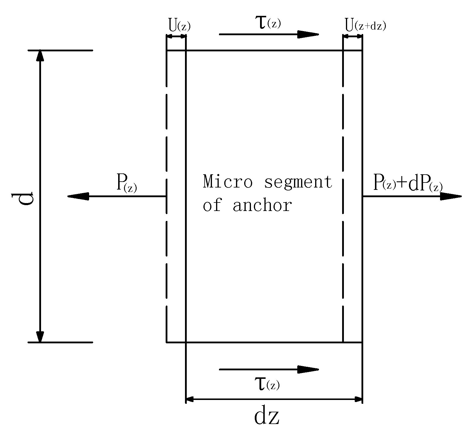
2. The Mechanical Principle of the Interfacial Bond between the Rock Bolt and the Grouting Body

It is generally believed that the bond-slip is divided into three stages according to the failure process of tensile test. These stages are the elastic stage, the plastic slip stage, and the residual shear stage [5]. Under the action of axial tensile force, when shear stress on the surface between the rock bolt and the grouting body is smaller than the shear strength on the interface, the tensile force at this time is less than the ultimate tensile force under an elastic state. Under a complete elastic state, there is no relative displacement between interfaces. When the tensile force increases continuously, once the shear stress on the surface between the rock bolt and the grouting body is greater than the shear strength on the interface, the extrusion plastic zone will develop in the front of the deformation plane. The extrusion plastic zone will expand continuously and form a squeezing wedge accumulation and a new extrusion slip surface. When the extrusion slip surface is crushed, the interface will slip and come into the plastic flow state. With a further increase in tensile force, shear stress decreases significantly and transverse fracture and failure happen on the anchorage body. Finally, the anchorage body is then separated from the hole wall and enters the residual shear stage [18]. Shear stress on the interface of the anchorage body increases with the increase in tensile force. The variations are shown in Figure 1.
Considering shear strength between the rock bolt and grouting body and supposing that the anchorage body material conforms to Hooke’s law, along the direction of the rock bolt length, a micro rock bolt segment whose length is dz is taken at the place where the distance from the pull end is z, as shown in Figure 2. On the supposition that axial displacement u ( z ) is produced under the action of axial force P ( z ) , according to the static equilibrium relationship and the principle of the load transfer method, it can be concluded that the shear displacement of z at any position on the interface between the anchorage body and the rock bolt equals the value of the axial displacement of the rock bolt under the action of tensile force (this does not consider the deformation of the rock bolt itself) [5].
When the calculated position of z on the interface between the rock bolt and the grouting body is at the position of j on the strain gauge, combined with Equation (1) and based on the variation in strain value of the strain gauge at each point, which is arranged along the axial direction of the rock bolt, Equation (2) can be obtained. Equation (2) is used to calculate the axial force at point j. According to the strain value of two adjacent points and Equation (3), the average value of shear stress on the interface between the rock bolt and the grouting body of two adjacent points can be obtained [19].
ε ( z ) = d u ( z ) d z = P ( z ) A E
P ( j ) = ε ( j ) E A
τ ( i ) = [ ε ( j ) + ε ( j + 1 ) ] E A π d Δ z
where P ( j ) is the calculated value of the axial force at the point j; τ ( i ) is the average value of shear stress between point j and point j + 1. ε ( j ) and ε ( j + 1 ) are the strain values measured by the strain gauge at the point j and point j + 1; E is the elastic modulus of the rock bolt. A and d are the cross-sectional area and diameter of the rock bolt rod, respectively; Δ z is the distance between adjacent strain gauges.

3. Test Schemes

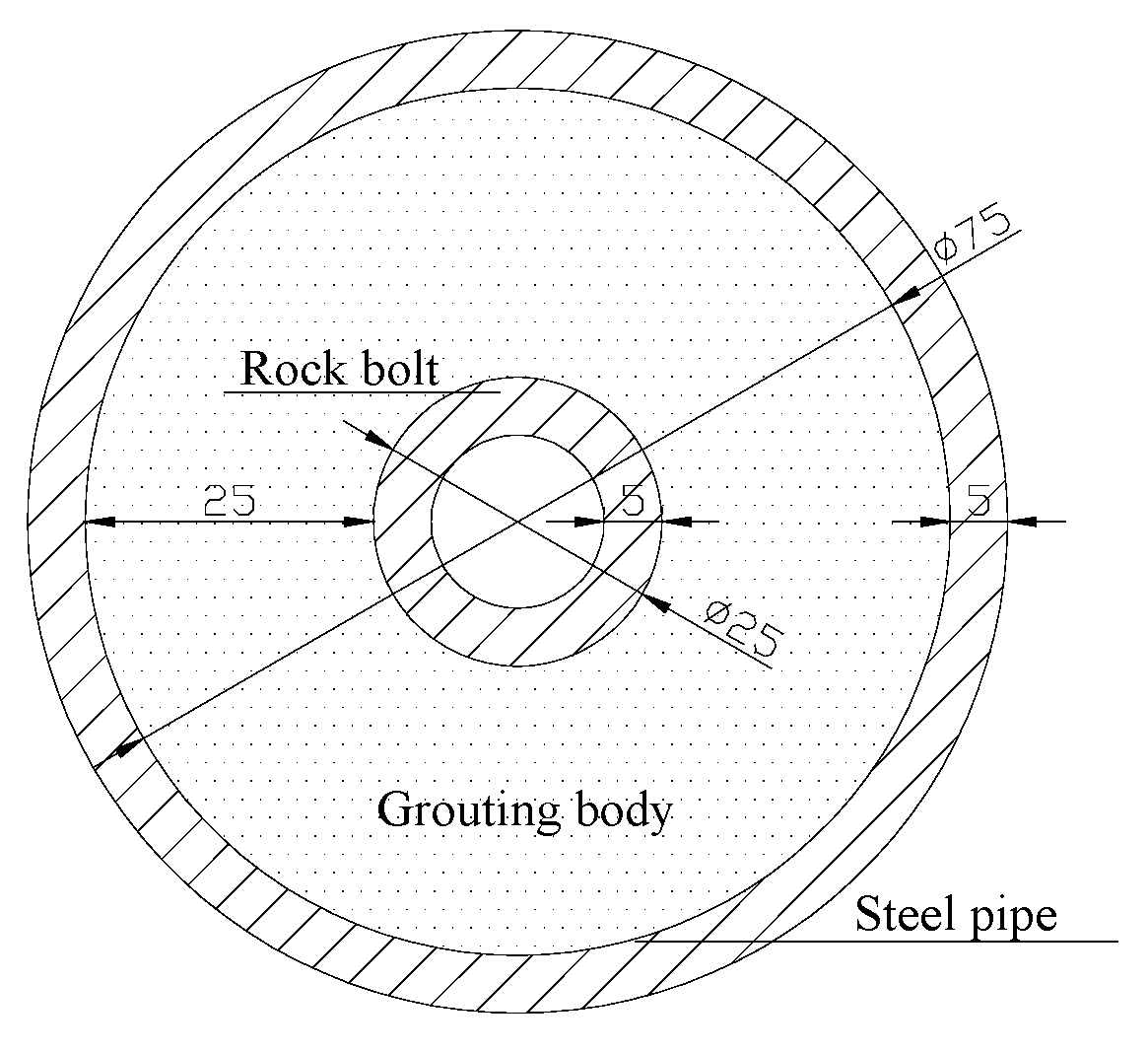
3.1. Test Introduction

In this test, an ordinary hollow thread rock bolt was used. Cement mortar with a water/cement ratio of 0.45 and a cement/sand ratio of 1.00 was used as the grouting material. Three anchorage body specimens whose anchorage section lengths were 100 cm were made. Strain gauges were attached to the surface of the rock bolt along the axial direction. The anchorage body specimens were then maintained in a constant temperature box at temperatures of 20 ± 0.2 °C, 35 ± 0.2 °C, and 50 ± 0.2 °C, respectively. Indoor tensile tests were then carried out for all specimens after 28 days of environmental. During the procedure of step loading, the strain value at the mark position on the interface under each step loading was recorded. The first step loading of the test was 5 kN. Afterwards, each level of load was 10 kN. The tests were stopped when the load reached 110 kN.

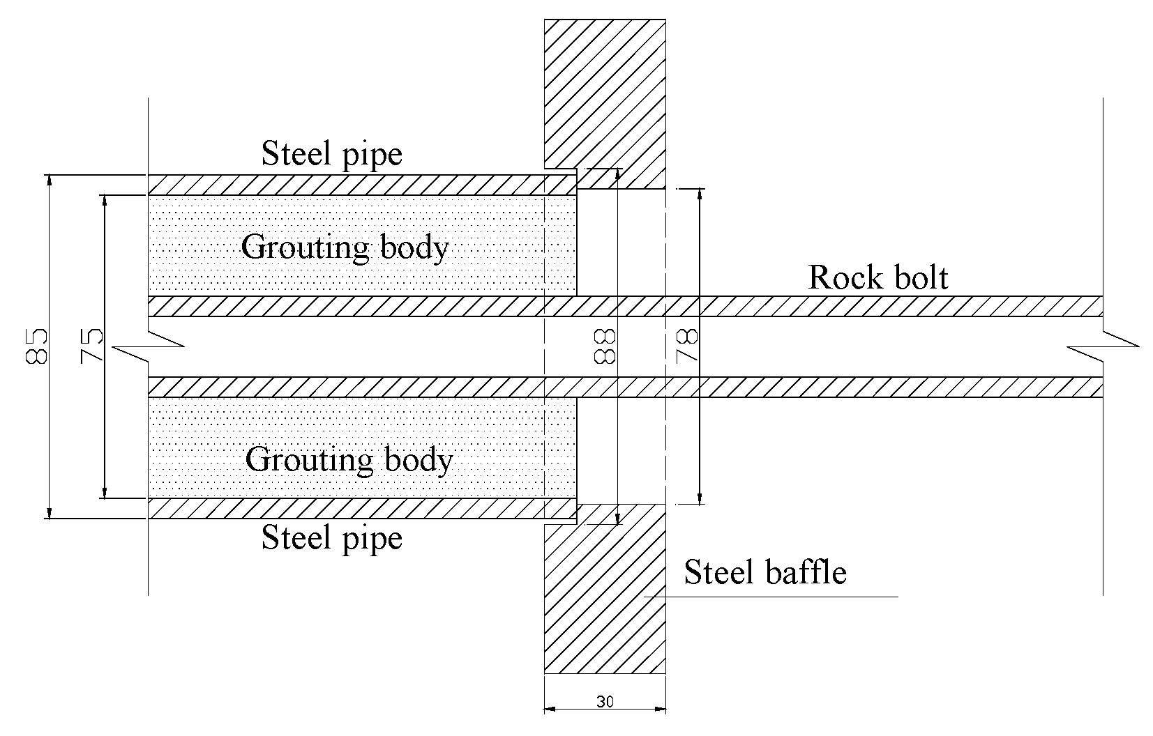
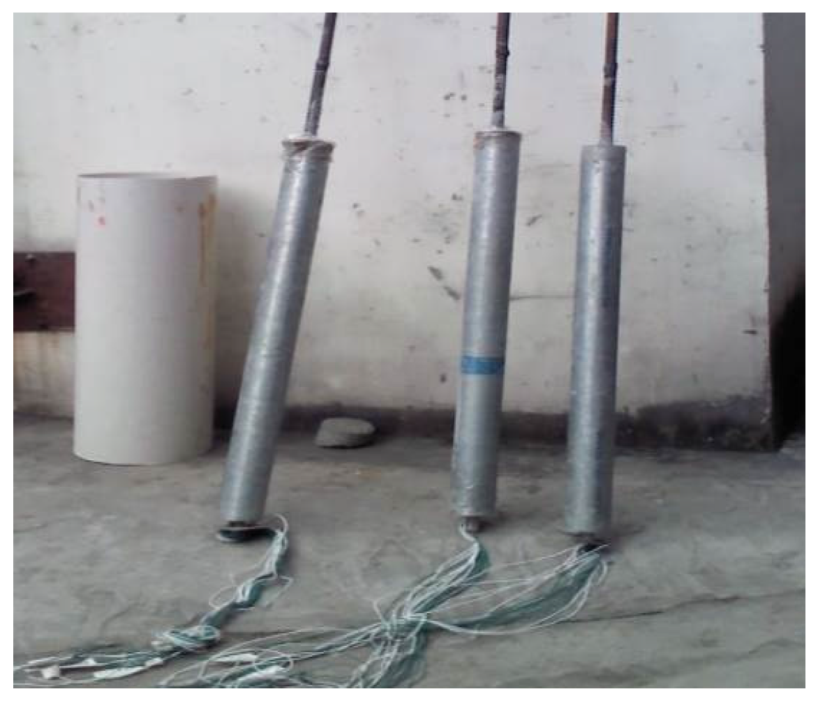
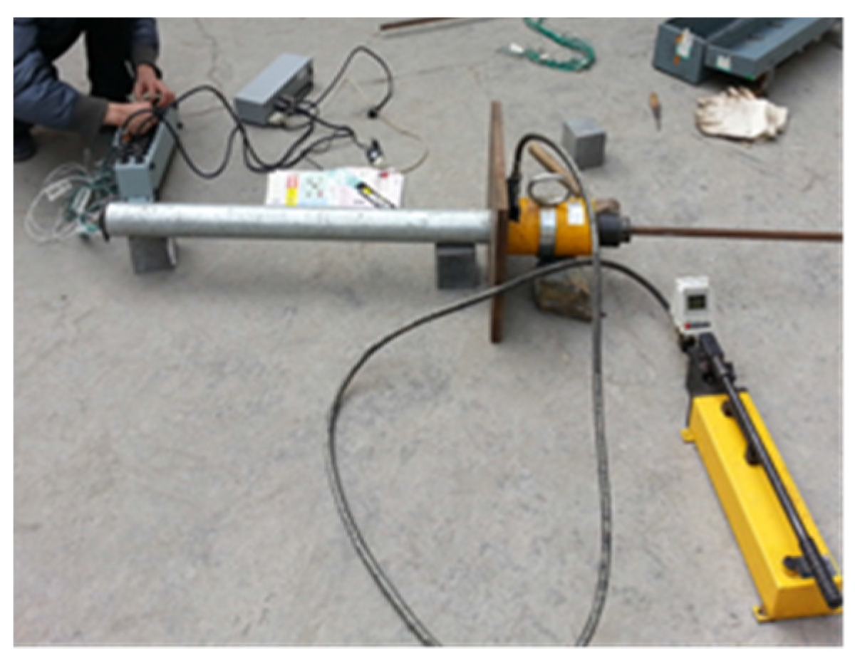
3.2. Test Materials and Device

(1) Test materials
Rock bolt: Rock bolts complying with standard TB/T 3209-2008, “Technical condition of hollow rock bolt” were provided by Hangzhou Tuqiang Engineering Materials Co., Ltd. (Hangzhou, China). The types of the rock bolt were ϕ 25 × 5 . In order to measure the tensile properties of the rock bolts and study the effects of temperature stress on performance, according to the requirements of the Chinese national standard, “Metallic Materials Tensile Testing at Ambient Temperature (GB/T 228-2002),” these rock bolts were sampled, marked, and stretched. Test results for the mechanical performance of these rock bolts are shown in Table 1.
Cement: The type of the cement was P·O 42.5 Lafarge ordinary Portland cement produced by Dujiangyan City, Sichuan Province. The density of the cement was 3.1 g/cm3, the specific surface area was 328 m2/kg, and the water requirement of normal consistency was 26.8%. The main parameters are shown in Table 2. Detection results showed that all indicators met the Chinese national standard requirements.
Steel pipe: Seamless steel pipes of type DN75 were used. The wall thickness was 5 mm and the material type was Q235.
Resistance strain gauge: Type BFH120-3AA gauges with a resistance value of 119% ± 0.2% were used. The sensitivity coefficient and sensitive gate size were 2.05% ± 0.23% and 6.9 mm × 3.9 mm, respectively. It is a kind of self adhesive strain gauge.
Strain gauge binder: Cyanoacrylate adhesive 502 produced by a Beijing chemical plant (Beijing, China) and South 704 silicone rubber produced by Liyang Kangda Chemical Co., Ltd. (Liyang, China) were used. The binder could endure temperatures from −50 °C up to +250 °C, conforming to Q/320481KD-001-2010, “Single Pack Room Temperature Environmental Silicone Rubber Executive Standard.”
(2) Test instrument
Static strain gauge: The static strain gauge was a model JC-4A produced by the Beijing Chuanger Building Test Technology Development Co., Ltd. (Beijing, China) and was connected to a PC through the CAN bus.
Rock bolt shank tension meter: The model YML-30B rock bolt shank tension meter was produced by Shanghai ShenRui Testing Equipment Co., Ltd. (Shanghai, China).

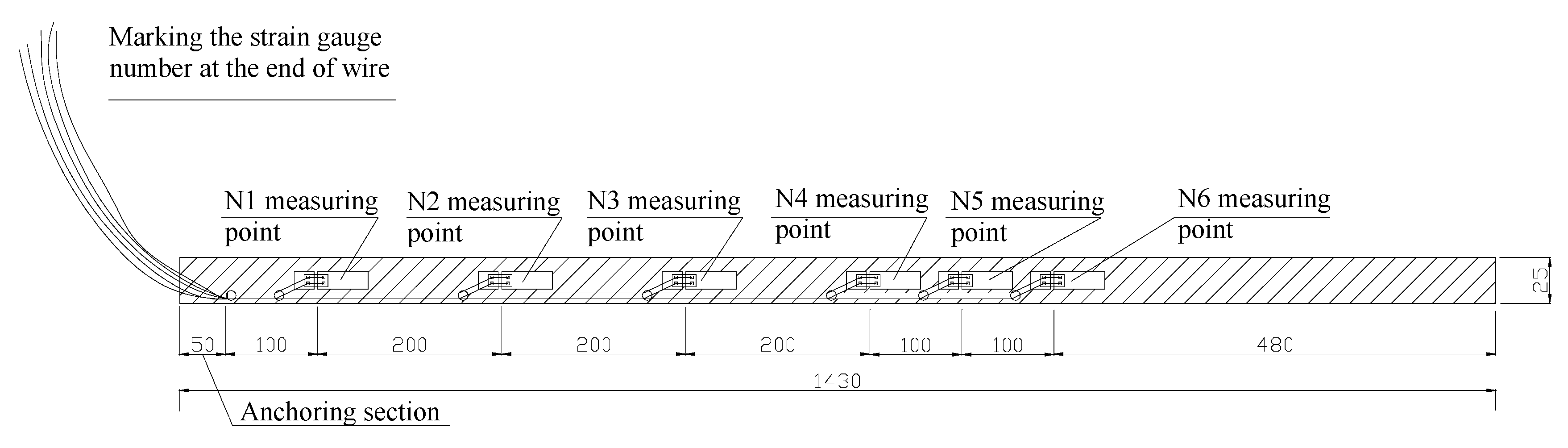
3.3. Strain Gauge Layout and Test Procedure

Considering the distribution of shear stress along the length of the rock bolt under axial load, strain gauges were mostly arranged around the tensile end of the rock bolt rod. The distance between strain gauges changed from 20 cm to 10 cm. Longitudinal strain gauges were attached on the surface of the rock bolt rod along the length direction and each strain gauge had a number. The specific layout of the strain gauge is shown in Figure 3. Three specimens produced under environmental temperatures of 20 °C, 35 °C, and 50 °C, labeled D2, D3, and D5, respectively, were tested.
The specific steps of this test are as follows: ① Firstly, the surface of the measuring point is ground with a grinding wheel and scrubbed with acetone, and the coordinate line of strain gauge is drawn. Secondly, the bottom of the strain gauge and the surface of the measuring point are brushed with a thin layer of binder. Strain gauges are attached to the surface of the rock bolt along the axial direction according to design requirements. The bubbles and excess binder are squeezed out until the strain gauge is tightly bonded to the rock bolt. Thereafter, protection and sealing treatment are carried out. A thin layer of the silica gel is attached to the strain gauge. ② The steel pipes, which are 100 cm long, are used as the forming die. Rock bolts with strain gauges are inserted into the middle of the steel pipes, leaving a reserved length at the end of 5 cm in the lower portion. ③ The gap between the steel pipe and the rock bolt is filled with configured cement mortar. The thickness of the cement mortar surrounding the bolt is 25 mm, as shown in Figure 4 and a hammer is used to tap on the bottom of steel pipe to make sure the concrete was condensed. ④ Shrinkage curves of cement mortar in a high temperature environment have been previously obtained. The shrinkage mainly occurs at an early age, within 3 days. Then, the shrinkage rate slows down and becomes steady. Thus, molded specimens are maintained in a standard environmental environment for 1 day as shown in Figure 5. ⑤ Molded specimens are maintained under respective temperatures for 28 days. ⑥ Tensile tests are carried out on all specimens as shown in Figure 6 and Figure 7. When the load is applied, the steel baffle and steel pipe form a reaction frame depending on the friction between steel pipe and grouting material. The load will be transferred to a rock bolt. Test data and observation are recorded.

4. Results and Discussion

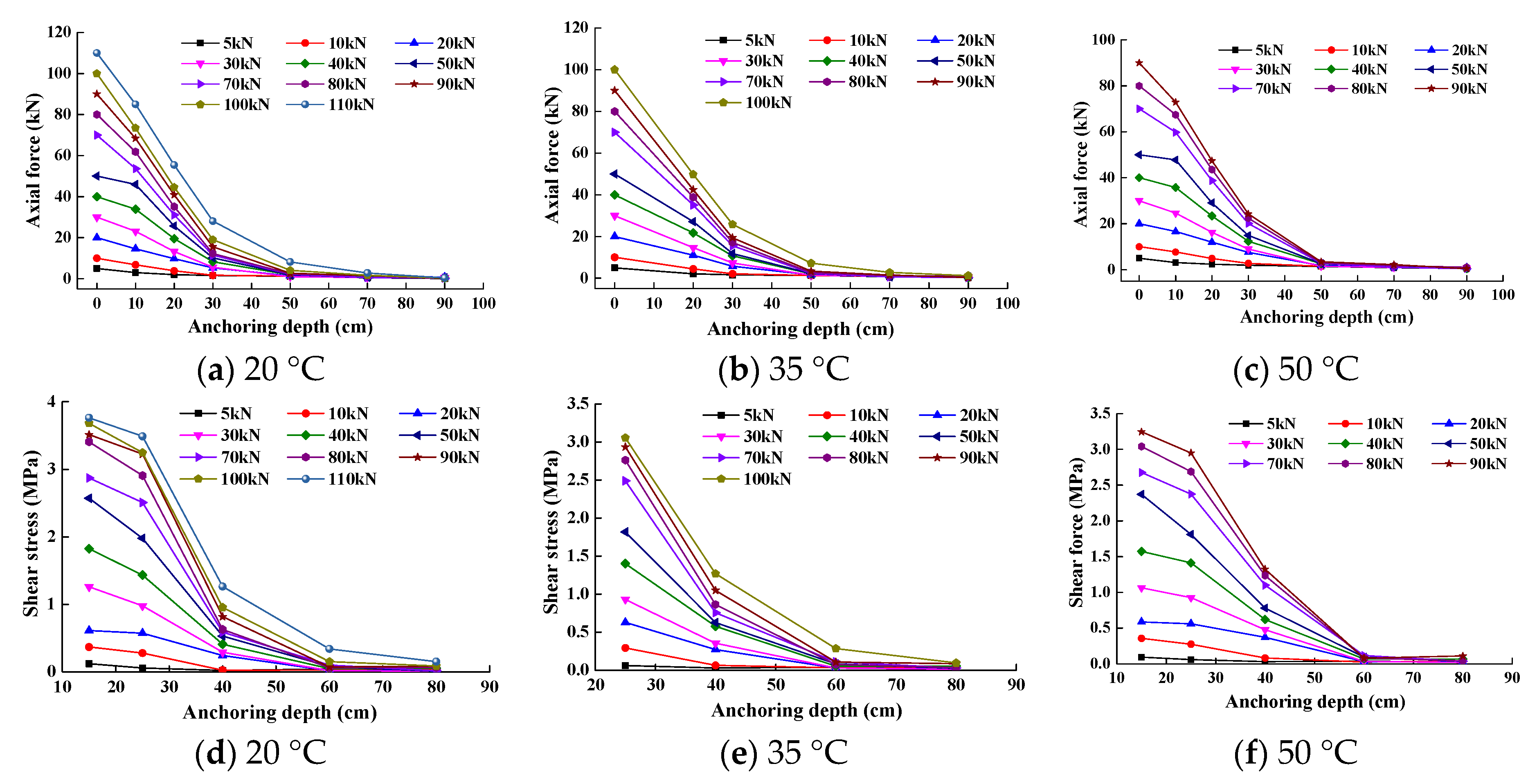
4.1. Distribution of Internal Force under Different Loads

According to Equations (2) and (3), the axial force and average shear stress of the bonding interface of the anchorage body specimen can be obtained after processing test data. Through the action of tensile force, the distribution curves of the axial force and shear stress along the length of the anchorage body under environmental temperature of 20 °C, 35 °C, and 50 °C were obtained and are shown in Figure 8.
As can be seen from Figure 8a, the axial force on the interface of Specimen D2 decreases gradually from the pull end of the anchorage section to the non-pull end under different loads. With an increase in tensile force, the shape of the curve rises slightly upward. Moreover, the maximum shear stress at the pull end of the anchorage section increases correspondingly and tends to zero as it comes close to the end (Figure 8d). On the supposition that it has entered the stage of elastic-plastic reinforcement, the shear stress reaches its peak value near the end of the anchorage section and the peak value moves continuously parallel along the length of the anchorage body.
During the test procedure of Specimen D3, the strain gauge, which was 10 cm from the pull end of the anchorage section, was damaged. The axial force value at a distance of 10 cm from the pull end of the anchorage section and the shear stress distribution value at a distance from the pull end of less than 25 cm were missing. When tensile force was increased to 110 kN, the strain gauges near the pull end of anchorage section had already failed. As can been seen from Figure 8b,e, the variation in axial force and shear stress on the interface of the rock bolt specimen along the length of the anchorage body is similar to that of the 20 °C specimen (D2). Axial force and shear stress all gradually decreased from the pull end to the opposite end of the anchorage section until they became zero.
In the case of Specimen D5, the average shear stress value of the anchorage section at the top 10 cm could not be obtained due to failure of the strain gauge. When the tensile force was increased to 90 kN, the reading of the strain gauge near the pull end of the anchorage body was abnormal. Figure 8c,f show that the variation in shear stress and axial force along the length of the anchorage body is almost the same at 20 °C and 35 °C. Axial force and shear stress all gradually decreased from the pull end to the non-pull end until they became zero.

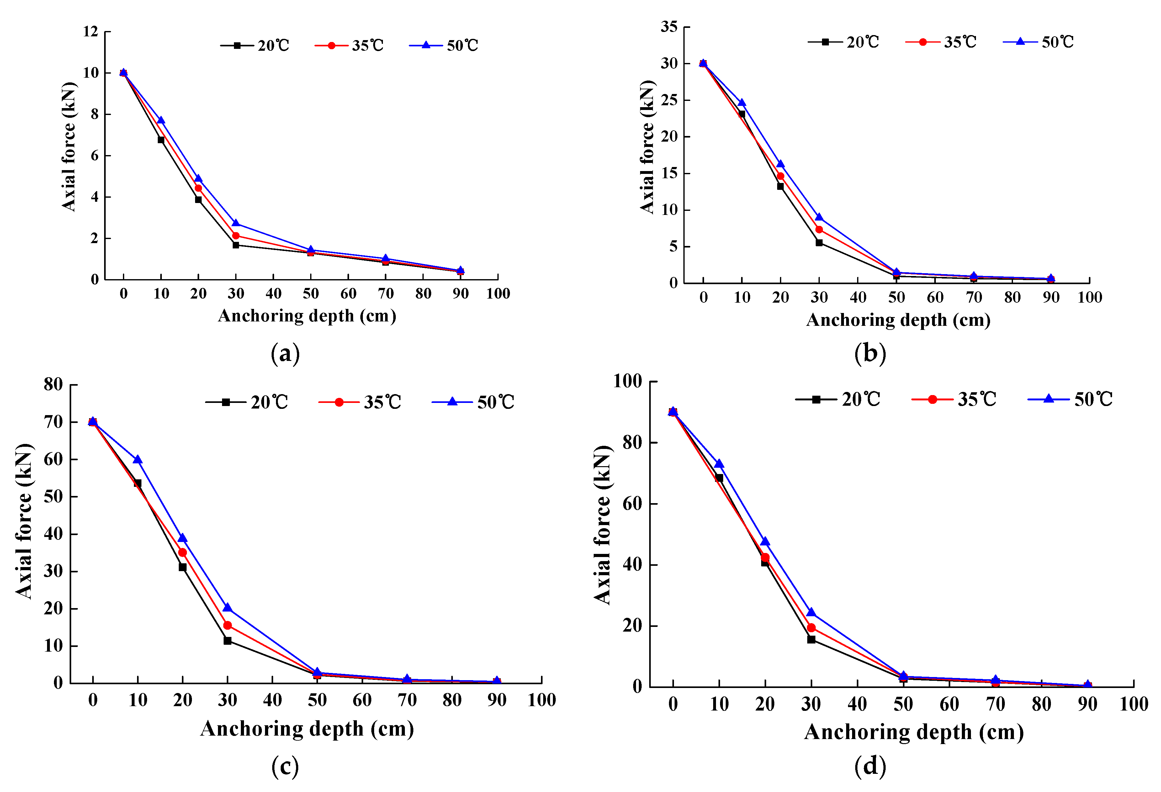
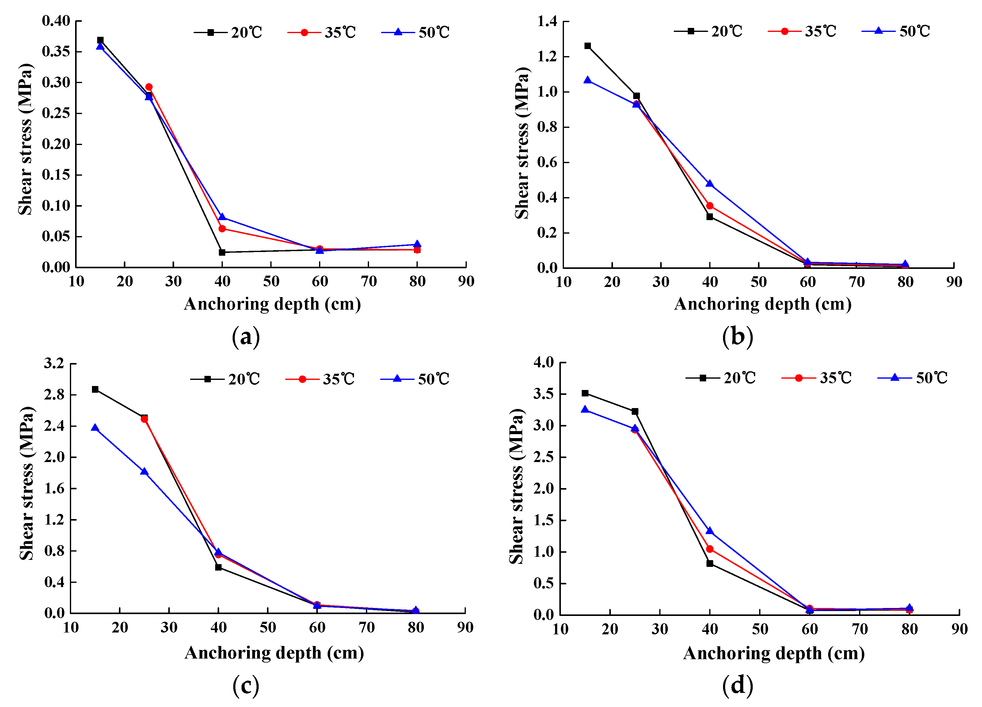
4.2. Effect of Temperature on the Axial Force and Shear Stress on the Interface of Specimens

Analysis of temperature effects on the distribution of axial force and shear stress of the anchorage section was achieved by changing the physical and mechanical properties of anchorage material. The ratio of elastic modulus in forming the medium of anchorage system has a large impact on the value and the distribution form of axial force and shear stress of the rock bolt. When the value and the distribution of axial force and shear stress of the anchorage body under the action of high temperature were analyzed, the data of four representative groups whose tensile force were 10 kN, 30 kN, 70 kN, and 90 kN were chosen, and relevant analyses were carried out.
(1) Effect of temperature on axial force
From Figure 9, it can be seen that, under the same tensile force, with an increase in environmental temperature, the axial force along the length of the anchorage body decreases more slowly. Decay law along the length of the anchorage body is the slowest at an environmental temperature of 50 °C, followed by axial force at 35 °C and 20 °C. With an increase in temperature, the axial force at the same place from the pull end of the anchorage body becomes larger.
(2) Effect of temperature on shear stress
From Figure 10, it can be seen that, under the same tensile force, with an increase in temperature, the decay law of shear stress along the length of anchorage body becomes slower. At the point near the pull end of the anchorage body, with an increase in temperature, the maximum value of shear stress becomes smaller which means the interface bond strength between rock bolt and grouting body decreases gradually. With an increase in temperature, when the depth exceeds a certain value along the length of the anchorage body, the shear stress at the same point increases gradually, which means the distribution of the shear stress along the length of the anchorage body becomes more uniform.
It can be seen from the above result that the axial force and shear stress all gradually decreased from the pull end to the non-pull end until they became zero. High temperature has little influence on the fully grouted rock bolt used in tunnel support construction with high geothermal activities. If the surrounding rock is a kind of nonabsorbent rock, the surrounding rock will prevent the evaporation of water in the process of cement hydration. If the surrounding rock is absorbent rock, water will evaporate, which will affect the performance of the anchorage system. Thus, it is very important to take measures to avoid the evaporation of water during the strength growth process in future anchor construction.
The anchorage system is a heterogeneous material. The stress distribution is not to be linear, with the maximum load at the rock bolt head and zero stress not at the end. The point of zero stress is called the critical point. The critical length is different because of a different diameter, the roughness of the rock bolt, and a different strength of grouting material. Therefore, it is suggested that the design length of the rock bolt be longer than the critical length.

5. Conclusions

In this paper, the size and distribution of axial force and shear stress on the interface of fully grouted rock bolts produced under different environmental temperatures are studied systematically, with the following conclusions obtained:
(1)
With an increase in environmental temperature, the maximum shear stress on the interface between rock bolt and grouting body becomes smaller, while the distribution of shear stress along the length of the anchorage section becomes relatively uniform. A high temperature has little influence on the fully grouted rock bolt used in tunnel support construction with high geothermal activities. It is very important to avoid the evaporation of water during the strength growth process in future anchor construction.
(2)
With an increase in tensile force, the axial force and maximum shear stress on the interface between the rock bolt and the grouting body along the anchorage section increase correspondingly. Axial force and shear stress all gradually decreased from the pull end to the non-pull end until they became zero. The design length of the rock bolt should be longer than the critical length.
(3)
The performance of the anchorage system is also related to other factors except high geothermal The deformation of the surrounding rock will produce a large tensile force on the rock bolt. The coupling of high temperature and load will lead to further deterioration of the anchorage system. In addition, the roughness of the surrounding rock will affect the ultimate pull-out force of rock bolts. These are very important research areas for the future.

Acknowledgments

The authors are very grateful for the funding from projects 51308471, 51378434, and 51578456 supported by the National Natural Science Foundation of China. Their thanks also go to the Fundamental Research Funds for the Central University with Grant No. 2682015ZD13. The first author wishes to thank the Key Laboratory of High-speed Railway Engineering, Ministry of Education, Southwest Jiaotong University, People’s Republic of China, for its support.

Author Contributions

Fuha Li and Xiaojuan Quan conceived and put forward the research ideas. Bo Wang, Yi Jia and Siyin Chen designed the test project. Fuhai Li and Guibin Zhang carried out the research and wrote the paper.

Conflicts of Interest

The authors declare no conflicts of interest.

References

  1. Hu, T.; Zhu, B.; Zheng, J.; Liang, L. Numerical analysis of load transfer mechanism of recursive control rock bolt. J. Railw. Eng. Soc. 2013, 7, 11–15. [Google Scholar]
  2. Phillips, S. Factors Affecting the Design of Anchorages in Rock; Cementation Research Ltd.: London, UK, 1970. [Google Scholar]
  3. You, C. Theory and application study on stress-transfer mechanism of anchoring system. Shandong Univ. Sci. Technol. 2005, 24, 1272–1272. [Google Scholar]
  4. Zhang, J.; Tang, B. Hyperbolic function model to analyze load transfer mechanism on bolts. Chin. J. Geotech. Eng. 2002, 24, 188–192. [Google Scholar]
  5. Zhong, Z.; Lv, L.; Deng, R. Mechanicalanalysis of wholly grouted bolt considering axial distribution along the bars. J. Disaster Prev. Mitig. Eng. 2013, 33, 311–315. [Google Scholar]
  6. Zhang, P.; Yin, K. An analysis method of the whole working course for the force transferring mechanism in fixed segment of tensile-type anchor bar. Chin. J. Undergr. Space Eng. 2009, 5, 716–723. [Google Scholar]
  7. Huang, M. Analysis on Pullout Load Transfer Mechanism of Geotechnical Anchor and Its Validating Monitor with Smart FRP Anchor. Ph.D. Thesis, Harbin Institute of Technology, Harbin, China, July 2014. [Google Scholar]
  8. Delhomme, F.; Debicki, G.; Chaib, Z. Experimental behaviour of anchor bolts under pullout and relaxation tests. Constr. Build. Mater. 2010, 24, 266–274. [Google Scholar] [CrossRef]
  9. Deb, D.; Das, K.C. Modelling of fully grouted rock bolt based on enriched finite element method. Int. J. Rock Mech. Min. Sci. 2011, 48, 283–293. [Google Scholar] [CrossRef]
  10. Xu, H.; Wang, W.; Jiang, M.; Dong, Q. Theoretical analysis of pullout deformation and stiffness of grouted rock bolts. Chin. J. Geotech. Eng. 2011, 33, 1511–1516. [Google Scholar]
  11. Zhang, W.; Liu, Q. Synthetical deformation analysis of anchor bolt in jointed rock mass. Rock Soil Mech. 2012, 33, 1067–1074. [Google Scholar]
  12. Yao, X.; Li, N.; Chen, Y. Theoretical solution for shear stresses on interface of fully grouted bolt in tunnels. Chin. J. Rock Mech. Eng. 2005, 24, 2272–2276. [Google Scholar]
  13. Zou, J.; Li, L.; Yang, X.; Wang, Z.; Zhao, H. Study on load transfer mechanism for span-type anchor based on the damage theory. J. China Railw. Soc. 2007, 29, 84–88. [Google Scholar]
  14. Abdelmoneim Elamin Mohamad, A.-B.; Chen, Z. Experimental and numerical analysis of the compressive and shear behavior for a new type of self-insulating concrete masonry system. Appl. Sci. 2016, 245, 1–14. [Google Scholar] [CrossRef]
  15. Zhang, A.; Gao, X. The feasibility of modified magnesia-phosphate cement as a heat resiatant adhesive for strengthening concrete with carbon sheets. Appl. Sci. 2016, 178, 1–13. [Google Scholar]
  16. Jia, X.; Yuan, Y.; Li, C.-F. Experimental study on bond behavior of new type cement grouted GFRP bolts. Chin. J. Rock Mech. Eng. 2006, 25, 2108–2114. [Google Scholar]
  17. Cheng, L.; Li, C.; Zheng, Y. Technical Code for Engineering of Ground Anchorage and Shotcrete Support; China Planning Press: Beijing, China, 2016. [Google Scholar]
  18. Xu, B. Analytical and Experimental Study on Adhesive Anchors. Ph.D. Thesis, Dalian University of Technology, Dalian, China, October 2006. [Google Scholar]
  19. Fang, Y.; He, C. Study on the interaction of whole bonded rock bolt and tunnel surrounding rock. Eng. Mech. 2007, 24, 111–116. [Google Scholar]
Figure 1. Shear stress variation law along with the tensile force: (a) elastic stage; (b) plastic slip stage; (c) residual shear stage.
Applsci 07 00327 g001
Figure 2. Schematic diagram of the interaction between rock bolts and the grouting body.
Applsci 07 00327 g002
Figure 3. Strain gauge layout (unit: mm).
Applsci 07 00327 g003
Figure 4. Section of rock bolts (unit: mm).
Applsci 07 00327 g004
Figure 5. Forming diagram of rock bolt specimens.
Applsci 07 00327 g005
Figure 6. Tensile test of rock bolts.
Applsci 07 00327 g006
Figure 7. Schematic diagram of rock bolts with steel baffle (unit: mm).
Applsci 07 00327 g007
Figure 8. Axial force and shear stress distribution diagrams under different loads: (a,d) for Specimen D2; (b,e) for Specimen D3; (c,f) for Specimen D5.
Applsci 07 00327 g008
Figure 9. The distribution diagrams of axial force under different tensile force. (a) Tensile force is 10 kN. (b) Tensile force is 30 kN. (c) Tensile force is 70 kN. (d) Tensile force is 90 kN.
Applsci 07 00327 g009
Figure 10. The distribution diagrams of shear stress under different Tensile force. (a) Tensile force is 10 kN. (b) Tensile force is 30 kN. (c) Tensile force is 70 kN. (d) Tensile force is 90 kN.
Applsci 07 00327 g010
Table 1. Mechanical parameters of rock bolts.
ParametersMaximum Tensile Force (kN)Cross Sectional Area (mm2)Ultimate Tensile Strength (MPa)Elongation (%)
Test values161.5314.251419.47
Table 2. Material parameters of cement.
ProjectFinenessInitial Setting Time (s)Final Setting Time (s)StabilityCompressive Strength (MPa)
3 d28 d
Test results3.9171259Qualified3049
National standards≤10>45<600/≥17≥42.5

