Improving Performance of Cold-Chain Insulated Container with Phase Change Material: An Experimental Investigation

1
Faculty of Architecture, Civil Engineering College, Ningbo University, Fenghua Street 818, Ningbo 315211, China
2
Fraunhofer Institute for Environmental, Safety, and Energy Technology UMSICHT, Osterfelder Strasse 3, Oberhausen 46047, Germany
*
Author to whom correspondence should be addressed.
Appl. Sci. 2017, 7(12), 1288; https://doi.org/10.3390/app7121288
Submission received: 26 October 2017
/
Revised: 17 November 2017
/
Accepted: 27 November 2017
/
Published: 11 December 2017
(This article belongs to the Special Issue Phase Change Material (PCM) 2017)
Abstract
:The cold-chain transportation is an important means to ensure the drug and food safety. An cold-chain insulated container incorporating with Phase Change Material (PCM) has been developed for a temperature-controlled transportation in the range of 2~8 °C. The container configuration and different preconditioning methods have been determined to realize a 72-h transportation under extremely high, extremely low, and alternating temperature conditions. The experimental results showed that the temperature-controlled time was extended from 1 h to more than 80 h and the internal temperature maintained at 4~5 °C by using a PCM with a melting/freezing point of 5 °C, while the container presented a subcooling effect in a range of −1~2 °C when using water as PCM. The experimental values of the temperature-controlled time agreed well with the theoretical values.
1. Introduction
Drug and food safety have become more important issues with a growing population and demand in recent years. In order to extend and ensure the shelf-life of pharmaceutical drugs or food, it is very important to keep their temperature at a given range through the storage and transportation processes. Such a temperature-controlled supply chain is called cold chain. Large quantities of drugs or food are normally transported by refrigerated trucks, while small quantities are delivered by containers. There are at least 1 million refrigerated road vehicles and 400,000 refrigerated containers worldwide [1]. They run on a vapor compressor that is driven by electric or fuel energy, and release amounts of greenhouse gas. It was reported that the cold chain is responsible for approximately 2.5% of global greenhouse gas emissions when considering both direct and indirect effects [2].
Thermal energy storage based on phase change materials (PCMs) is an advanced energy technology that has recently attracted increasing interest in cold-chain systems. PCMs are able to absorb or release amounts of thermal energy during the phase transition process, maintaining the internal temperature in an acceptable range. Many studies have indicated that the energy savings can be achieved by utilizing PCMs in cold-chain systems. For example, Ahmed et al. added PCM into the insulation layer of a refrigerated truck trailer. The inclusion of the paraffin-based PCM in the standard trailer walls was studied as a heat transfer reduction technology. An average reduction of 16.3% in total heat transfer from the exterior to the refrigerated truck was achieved by adding PCM to the insulation foam of the trailer walls [3].
Liu et al. developed an innovative refrigeration system incorporating PCM to maintain refrigerated trucks at the desired thermal conditions. The PCM storage tank was charged by a refrigeration unit when stationary and provides cooling when in service. An analysis showed that delivery of refrigerated products can be made with a PCM system having a weight that is comparable to that of an on board conventional refrigeration system, with less than half of the energy cost [4].
Fioretti et al. integrated an external PCM layer with a refrigerated container envelop to reduce and displace the heat flux phase caused by the external climatic conditions. It was found that a PCM-added layer helps to store the incoming heat load at a constant temperature during the melting phase. A reduction on peak heat transfer rate of 5.55% and 8.57% during two experimental days was observed in comparison with the reference [5].
Copertaro et al. presented the first numerical investigation of the energy behavior of a refrigerated container envelope that was fitted with PCMs. An organic PCM named RT35HC manufactured by Rubitherm® Technologies GmbH in Berlin in Germany, which has a melting peak temperature of 35 °C, was found to perform best on a typical summer day in Milan, Ancona, and Palemo. It was observed that the heat load peak was reduced by 20% and the peak was delayed for 2~3 h [6].
The above-mentioned studies focus on the trucks or containers having a refrigeration system. However, insulated containers integrated with PCMs are also an attractive alternative for cold-chain systems. Such containers do not use any conventional refrigerators, but a thermal energy storage of PCMs to control the internal temperature. The PCMs are normally preconditioned when stationary and provide cooling or heating when in service. The temperature-controlled time is mostly within 48 h due to the limited thermal capacity of PCMs and the poor insulation of the containers. For example, the company EMBALL’ISO in Saint-Georges-de-Reneins in France provides a packaging comprising a cardboard box, six vacuum insulation panels, and six PCM briquettes [7]. This packaging is normally used for an isothermal transportation up to 48 h at extreme temperatures.
In China, it usually takes two to three days for the drugs or food transportation between cities and the weather conditions could be very different in destination and departure sites. In order to meet this challenge, an insulated container with PCM panels has been developed for a 72-h transportation in the range of 2~8 °C, which is the most common temperature range for cold-chain systems. Different preconditioning methods have been determined for the application under various temperature conditions. The thermal performance of the container without PCM and with different PCMs have been experimentally investigated and compared with the results being theoretically calculated.
2. Materials and Methods
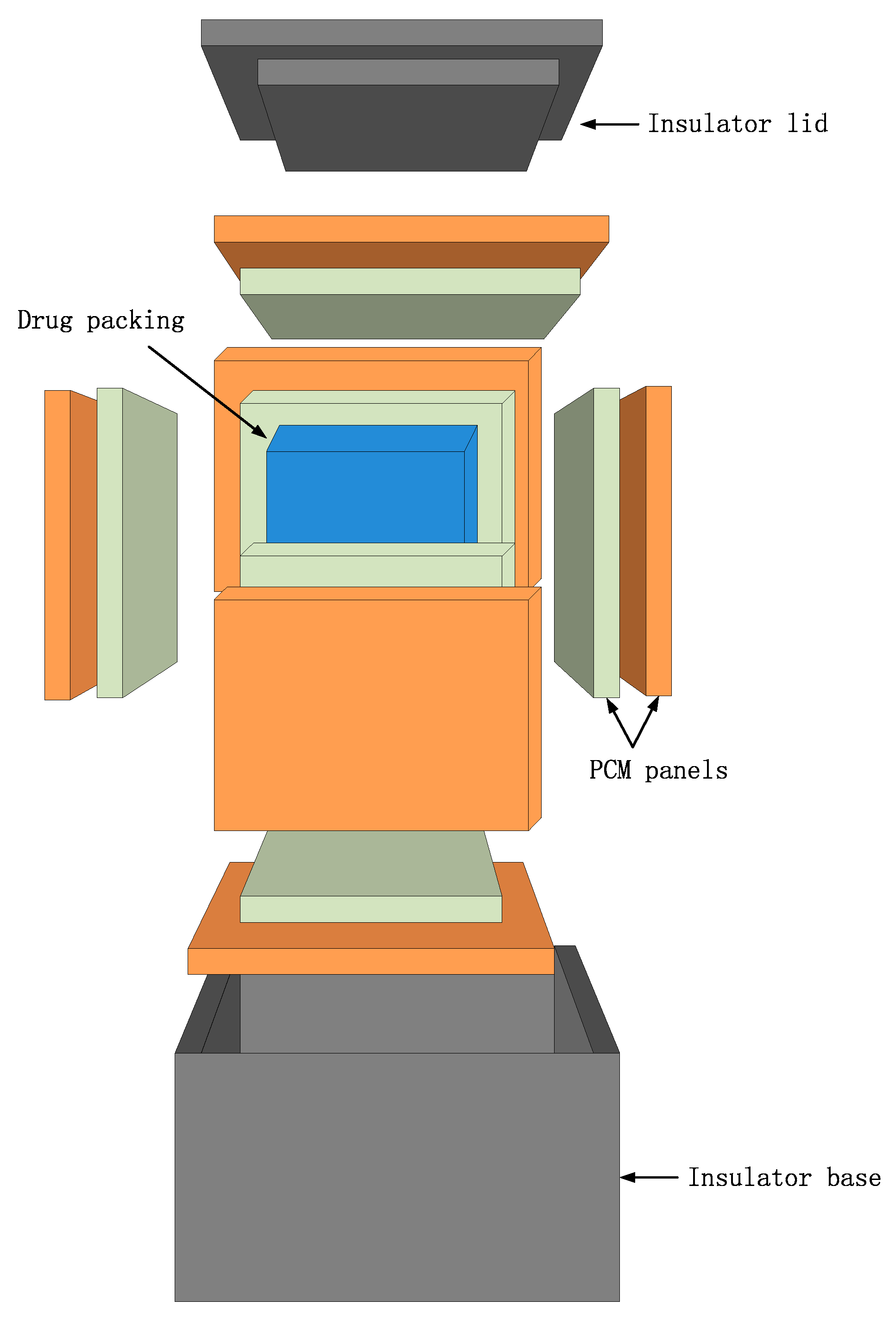
2.1. Configuration of Cold-Chain Insulated Container
As shown in Figure 1, the cold-chain insulated container is comprised of an insulator base, an insulator lid, and double-layer panels filled with PCM. The seamless and leak-proof insulator base was made with all-in-one foaming technology and has a high insulation performance. The external dimension of the base is 540 × 420 × 480 mm and the internal 420 × 300 × 360 mm. The insulation material has a sandwich structure, which consists of 10 mm polyurethane (PU), 10 mm vacuum insulation panel (VIP), and 10 mm polyurethane (PU), namely the VIP layer is enclosed by PU material. The thermal conductivity of the PU and VIP are 0.022 W/(m·K) and 0.005 W/(m·K), respectively.
Two layers of the PCM panels are inserted into the insulator base. The panels are made of high-density polyethylene (HDPE) and have an external dimension of 350 × 290 × 15 mm. Different preconditioning methods have been determined with the construction of the double-layer PCM panels, which contributes to a temperature-controlled transportation more than 72 h both at extreme temperatures and at alternating temperature.
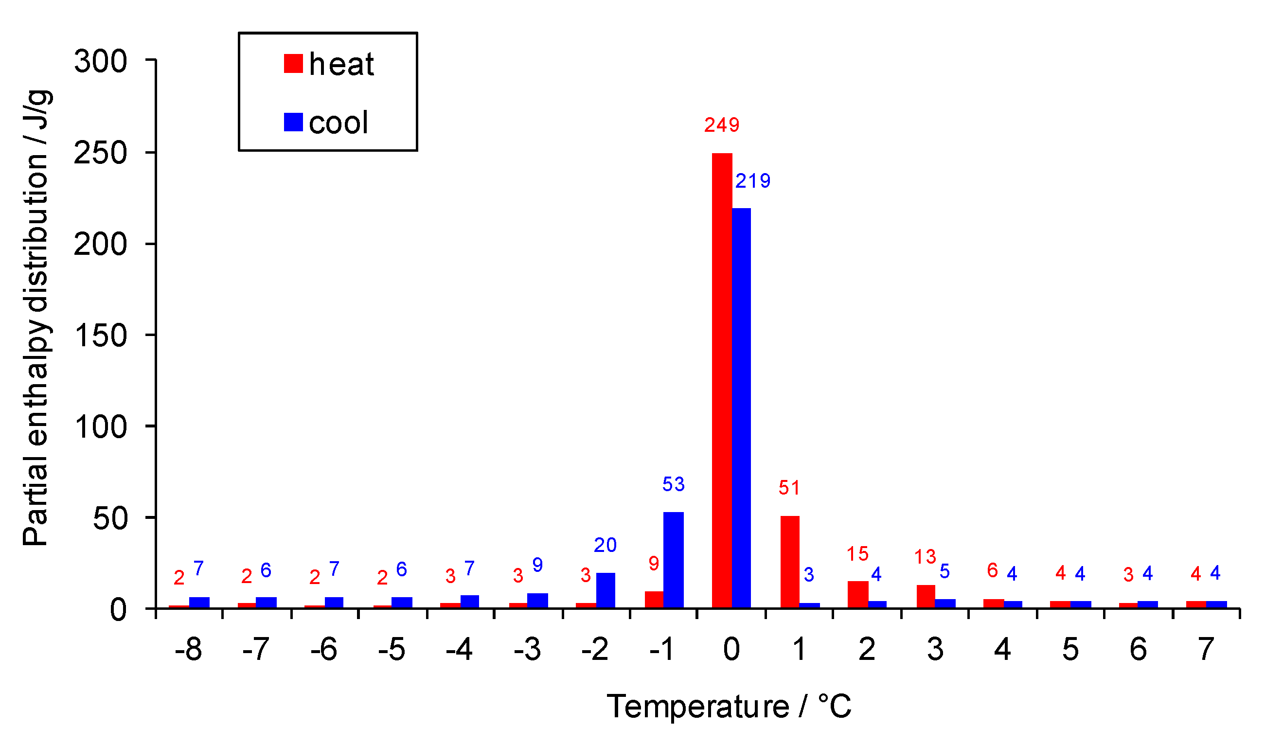
Water and an alkane mixture named OP5E manufactured by Ruhr New Material Technology Co., Ltd. in Hangzhou in China have been used as PCM in this paper. Their phase change temperature and enthalpy were analyzed with a three-layer calorimeter. Figure 2 and Figure 3 present the stored heat of water and of OP5E as a function of temperature in the case of heating/cooling respectively. The bars in the figures display the partial enthalpy of the material in a temperature interval of 1 K. The temperature, at which the maximal partial enthalpy appears, corresponds to the melting/freezing point of the material. From Figure 2 it can be seen that water has a melting/freezing peak at 0 °C and the total enthalpy is 340 kJ/kg between −2 °C and 4 °C, while OP5E has a melting/freezing temperature at 5~6 °C, and the total enthalpy is 235 kJ/kg between 2 °C and 8 °C (see Figure 3). Their technical parameters and the total mass used in the container are given in Table 1. The enthalpy and the total mass of water and OP5E were used for the heat transfer calculation in Section 2.2.
2.2. Heat Transfer Calculation
The following assumptions were made for the heat transfer calculations:
- (1)
- the ambient temperature and the air temperature inside the container distribute homogeneously; and,
- (2)
- the PCM’s temperature keeps constant and distributes homogeneously during the phase transition process.
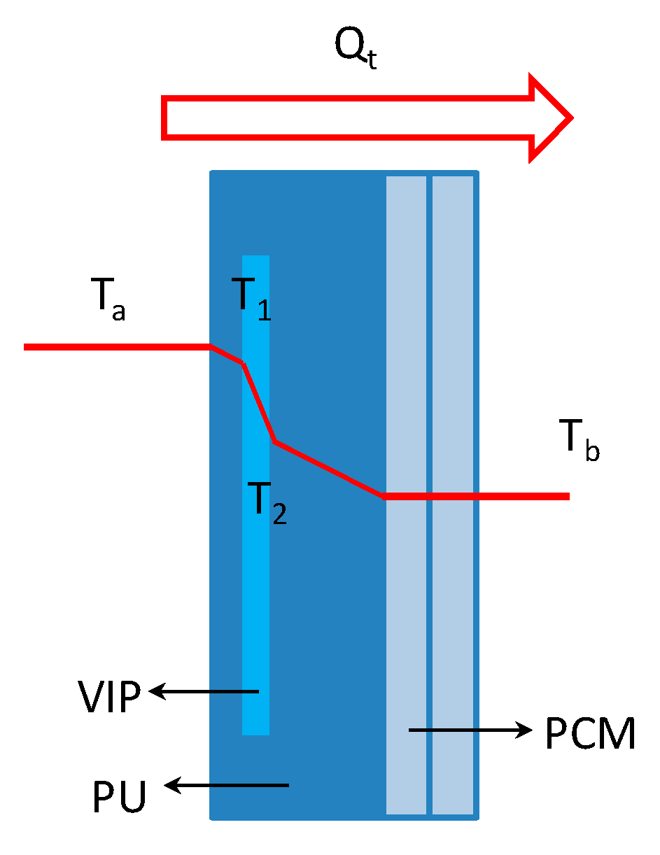
Figure 4 shows the heat transfer schema of the container at a high ambient temperature as an example.
The average heat transfer area F of the container can be calculated according to Equation (1) as follows:
where Fa and Fb are the external and internal area of the container respectively. It was obtained that F = 0.856 m2 by substituting data into Equation (1).
The overall heat transfer coefficient K of the container is obtained as follows:
where α1 and α2 are the heat transfer coefficient of air outside and inside the container. The air flows outside and inside the container can be considered as natural convection since the containers are normally transported in a closed cabin of refrigerated trucks or vans. The coefficient is 7.0~9.3 W/(m2K) for natural convection [8], here α1 = α2 = 8.0 W/(m2K). λ1, λ2 and λ3 are the thermal conductivity of PU, VIP, and PCM, respectively, here λ1 = 0.022 W/(m·K), λ2 = 0.005 W/(m·K), λ3 = 0.2 W/(m·K). δ1, δ2 and δ3 are the thickness of PU, VIP, and PCM, respectively.
Heat is transferred from the ambient into the container or conversely by conduction and convection. The heat flow q1 can be estimated with the overall heat transfer coefficient K, the average heat transfer area F, the ambient temperature Ta and the air temperature Tb inside the container as follows:
Tb is taken as the maximum temperature allowed in the container under extremely high temperature condition (Tb,max = 8 °C) or the minimum temperature allowed under extremely low temperature condition (Tb,min = 2 °C).
The heat flow q2 caused by air leakage is obtained according to Equation (4):
where is the additional thermal load factor, here .
The total heat flow q is the sum of the heat flow q1 and q2:
q = q1 + q2
The heat capacity ΔH of PCM can be determined as follows:
where m is the total mass of PCM and Δh is the melting/freezing enthalpy of PCM in a given temperature interval.
ΔH = m × Δh
The heat loads that are transferred from the ambient into the container are primarily absorbed by PCM. The air temperature inside the container maintains steady before the PCM are completely melted or frozen. Therefore, the temperature-controlled time t can be estimated with the heat capacity ΔH of PCM and the total heat flow q:
It can be seen that the temperature-controlled time depends on the phase transition temperature range, the melting/freezing enthalpy, and the mass of PCM that is used for the same container.
2.3. Experimental Method and Procedure
According to Chinese National Standard “Temperature control facilities of pharmaceutical products cold chain logistics—Specification for performance qualification”, the container performance should be determined for a temperature-controlled range between 2 °C and 8 °C under the following conditions:
- (1)
- under extremely high temperature condition, the ambient temperature is set at 35 ± 2 °C;
- (2)
- under extremely low temperature condition, the ambient temperature is set at −20 ± 2 °C; and,
- (3)
- under alternating temperature condition, the ambient temperature is set at 35 ± 2 °C for the first half of the time and −20 ± 2 °C for the second half of the time.
A temperature-controlled chamber was used to simulate the above-mentioned temperature conditions. Eight temperature sensors were put inside the container and one for the ambient, as shown in Figure 5. The time period, in which one of the measuring points firstly reaches the maximum or minimum temperature allowed, was taken as the temperature-controlled time of the container. All of the tests were repeated three to five times, and the typical results were presented in this paper.
The PCM could be either solid or liquid at the initial state according to the service temperature condition to take full advantage of the phase transition of the PCM. Therefore, the PCM panels were preconditioned to adapt to the three temperature conditions.
2.3.1. Preconditioning for the Use at Extremely High Temperature
The PCM should be fully frozen at the initial state for the application under extremely high temperature condition. Furthermore, the temperature of the PCM panels should not be too low to subcool or freeze drugs or foods. The preconditioning was carried out as follows:
- (1)
- place twelve PCM panels in a −20 °C freezer or below for a minimum of 48 h to ensure PCM was fully frozen;
- (2)
- place all frozen water panels in a 4~5 °C cooler for 60 h until the surface temperature reaches 0 °C, or place all frozen OP5E panels in a 4~5 °C cooler for 60 h until the surface temperature reaches 5 °C;
- (3)
- insert the PCM panels and temperature sensors into the container;
- (4)
- place the container and a temperature sensor into the temperature-controlled chamber; and,
- (5)
- set the chamber temperature at 35 °C and start the test.
2.3.2. Preconditioning for the Use at Extremely Low Temperature
The PCM should be fully melted at the initial state for the application under a extremely low temperature condition. Furthermore, the temperature of the PCM panels should not be too high to overheat drugs or foods. The preconditioning was carried out as follows:
- (1)
- place twelve PCM panels and the container in a 5~6 °C cooler for 8 h;
- (2)
- insert the PCM panels and temperature sensors into the container; and,
- (3)
- place the container and a temperature sensor into the temperature-controlled chamber.
- (4)
- set the chamber temperature at −20 °C and start the test.
2.3.3. Preconditioning for the Use at Alternating Temperature
The PCM should be half melted and half frozen at the initial state for the utilization under alternating temperature condition. It takes advantage of the construction of the double-layer panels in this case. Therefore, one layer of PCM panels was fully frozen and the other was kept in the liquid state. The preconditioning was carried out as follows:
- (1)
- place six PCM panels in a −20 °C freezer or below for 30 h;
- (2)
- place six PCM panels in a 5~6 °C cooler for 8 h;
- (3)
- insert the six frozen PCM panels into the container near to the drug or food packing and the other six cooled panels near to the insulator base.
- (4)
- insert the temperature sensors into the container; and,
- (5)
- place the container and a temperature sensor into the temperature-controlled chamber.
- (6)
- set the chamber temperature at 35 °C for the first half of the time and then −20 °C for the next half of the time and start the test.
3. Results and Discussion
3.1. Performance under Extremely High Temperature Condition
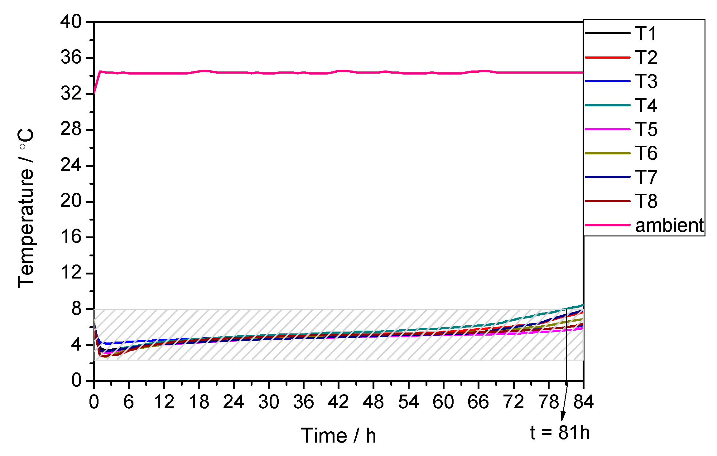
Figure 6, Figure 7 and Figure 8 present the ambient temperature and air temperature inside the container without PCM, with water as PCM and with OP5E as PCM under extremely high temperature condition, respectively. It can be seen that the temperature-controlled time was less than 1 h (about 54 min) by using the container without PCM. The performance was distinctly improved when incorporating a PCM into the container. However, the most measuring points inside the container showed a temperature at 1~2 °C for the first 70 h by applying water as PCM. This would cause a subcooling of drugs or food during the transportation. On the other hand, the air temperature inside the container was controlled in the range of 2~8 °C for 81 h by using OP5E as PCM. It kept at 4~5 °C for most of the time, which corresponds to the melting/freezing peak temperature of OP5E. In all three cases, the measuring point, which firstly exceeded the maximum temperature of 8 °C, was one of the points in the corner of the container, namely T1, T2, T3, or T4. The reason was that the tightness between the insulator base and lid is normally worse in the corner than elsewhere. Consequently, the heat transfer was intensified in the corner by the air leakage. Furthermore, it was observed that the air temperature in the container decreased firstly and then went up. The reason was that the container was not pre-cooled before the test because of the limited operation condition. The air in the container had the room temperature at the beginning and was firstly cooled when inserting the frozen PCM panels into the container. The air temperature began to rise when heat was transferred from the ambient to the inside of the container.
3.2. Performance under Extremely Low Temperature Condition
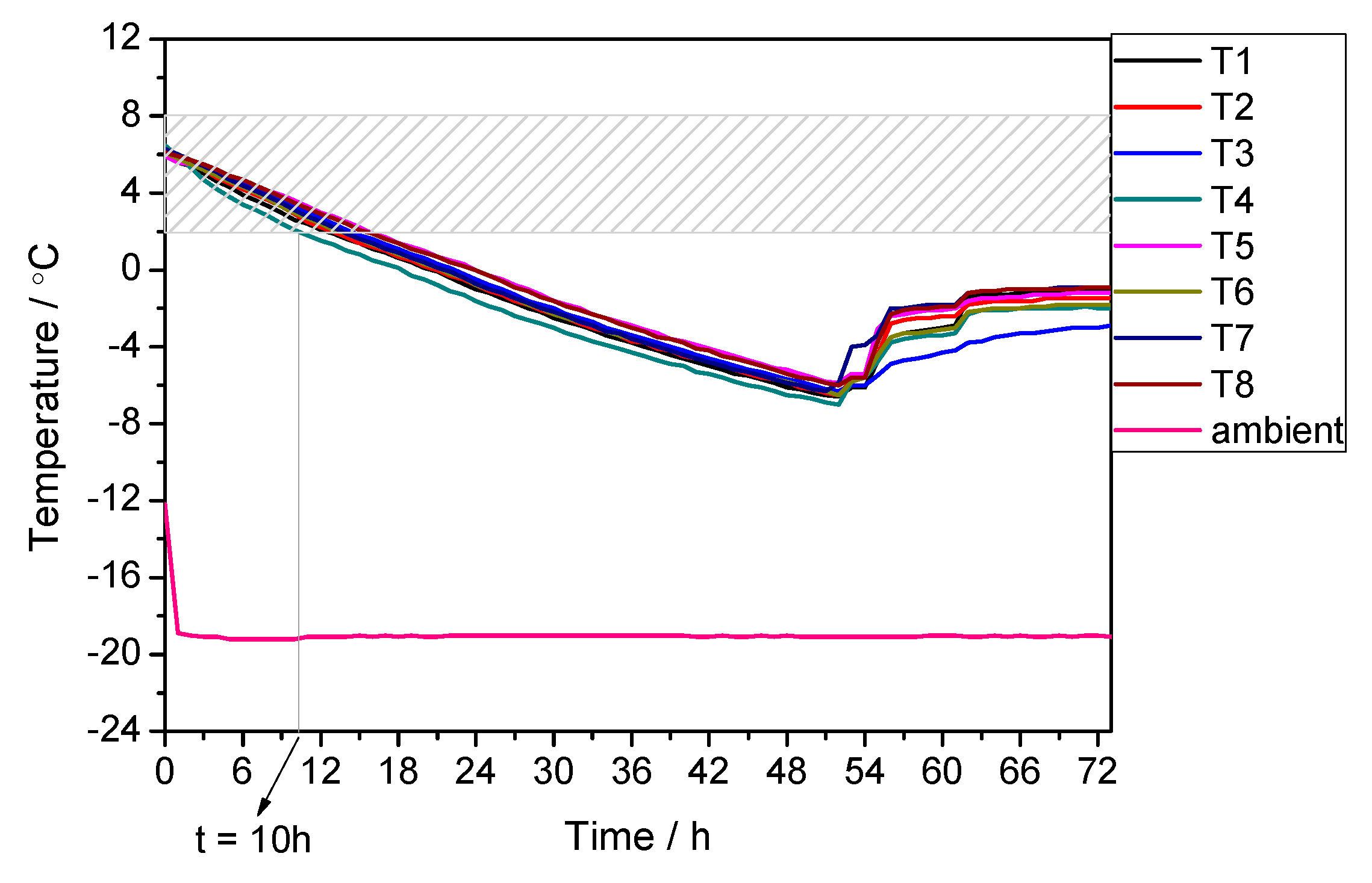
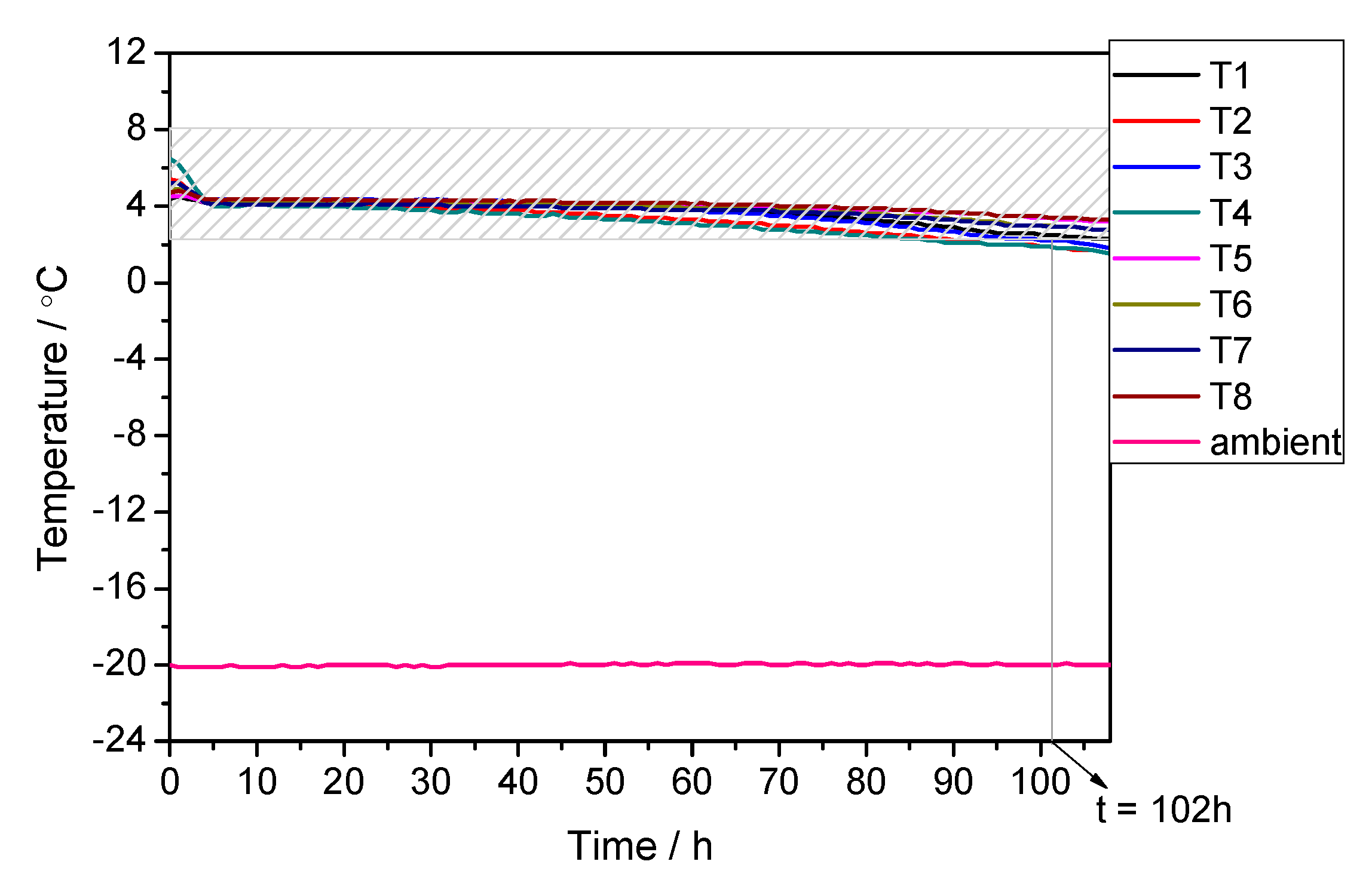
Figure 9, Figure 10 and Figure 11 present the ambient temperature and air temperature is inside the container without PCM, with water as PCM, and with OP5E as PCM under extremely low temperature conditions, respectively. It was observed that the temperature-controlled time was about 1 h (62 min) by using the container without PCM. This time was extended to 10 h when using water as PCM and to 102 h when using OP5E as PCM. The air temperature in the container dropped swiftly to −6 °C and rose to −1~−2 °C by applying water. This phenomenon could be caused by the subcooling of water. The nucleation of water did not occur until the air temperature in the container decreased to −6 °C. The air temperature increased when water began to freeze and amounts of heat were released during the liquid-solid phase transition. The temperature inside the container kept constant at −1~−2 °C until the nucleation process ended. On the other hand, the air temperature in the container maintained at 4~5 °C for the first 60 h and then decreased slowly to 2 °C after 102 h when using OP5E as PCM. In all three cases, the measuring point, which firstly exceeded the minimum temperature of 2 °C, was also one of the points in the corner as in the case under extremely high temperature condition.
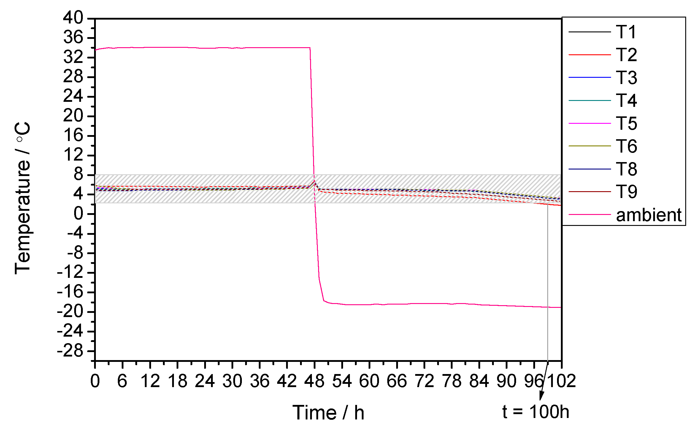
3.3. Performance under Alternating Temperature Condition
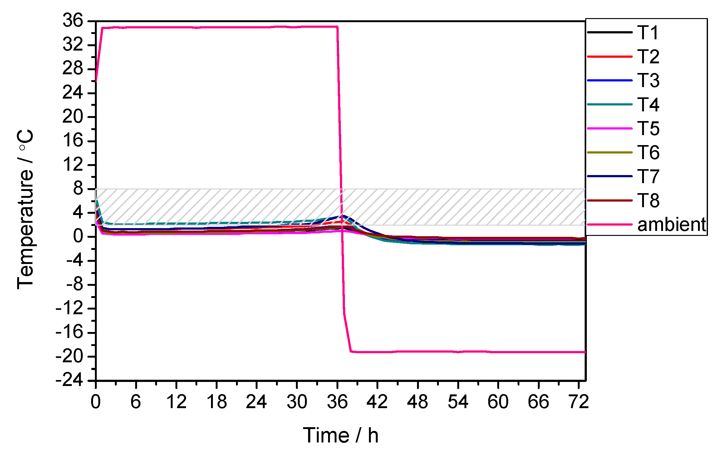
Figure 12 and Figure 13 show the ambient temperature and air temperature inside the container with water and with OP5E as PCM under alternating temperature conditions, respectively. The container without PCM was not tested under this condition since the holding time was just one hour at both of the extreme temperatures. The most measuring points in the container indicated a temperature below 2 °C when using water as PCM. The air temperature kept at 0 °C for the first 36 h and at −1 °C for the second 36 h. It may pose a subcooling risk to drugs or food. However, the container incorporated with OP5E maintained a stable internal temperature at 4~5 °C for the first 72 h and dropped to 2 °C after 100 h.
The experimental temperature-controlled time of the container with OP5E was compared with that theoretically calculated according to the equations in Section 2.2. From Table 2 it can be seen that the deviation was within an acceptable range of ±10%. The experiment error mainly resulted from the inhomogeneous temperature distribution inside the container. In most cases, the temperature in the corner firstly exceeded the maximum or minimum temperature that was allowed because of the air leakage.
4. Conclusions
A cold-chain insulated container integrated with PCM has been developed for a temperature-controlled transportation in a range of 2~8 °C. A 72-h transportation under various temperature conditions has been achieved with the high insulation performance of the container and the double-layer PCM panels. Different preconditioning methods have been determined to take full advantage of the phase transition of the PCM.
The container performance depends largely on the phase transition temperature range, the melting/freezing enthalpy, and the mass of that is PCM used. The container presented a subcooling effect in a range of −1~2 °C for 72 h under extremely high temperature and alternating temperature conditions by applying water as PCM. For the utilization at extremely low temperature, the holding time was only 10 h. However, the temperature-controlled time was extended from 1 h to more than 80 h by using a PCM with a melting/freezing point at 5 °C. Furthermore, the air temperature in the container was maintained at a steady at 4~5 °C for most of the time under extremely high, extremely low, and alternating temperature conditions, which would contribute to extending the shelf-life of drugs or food. The experimental values of the temperature-controlled time agreed well with the theoretical values. The results showed that the insulated containers with PCM could be an attractive alternative to refrigerated trucks or containers having a compressor for cold-chain systems.
Acknowledgments
This work was developed within the framework of the research project 2017C34002 “Development of isothermal packaging technology based on phase change materials (PCMs) and intelligent monitoring system” funded by Science Technology Department of Zhejiang Province of China.
Author Contributions
Li Huang conceived and designed the experiments; Udo Piontek performed the experiments and analyzed the data; Li Huang contributed materials and wrote the paper.
Conflicts of Interest
There are no conflicts of interest.
Nomenclature
| F | average heat transfer area of the container, m2 |
| Fa | external heat transfer area of the container, m2 |
| Fb | internal heat transfer area of the container, m2 |
| Δh | melting/freezing enthalpy of PCM, kJ/kg |
| ΔH | heat capacity of PCM, kJ |
| K | overall heat transfer coefficient, W/(m2·K) |
| m | total mass of PCM, kg |
| q | total heat flow, W |
| q1 | heat flow rate, conduction and convection, W |
| q2 | heat flow rate, air leakage, W |
| t | temperature-controlled time, h |
| Ta | ambient temperature, °C |
| Tb | air temperature inside the container, °C |
| α1 | air heat transfer coefficient outside, W/(m2·K) |
| α2 | air heat transfer coefficient inside the container, W/(m2·K) |
| additional thermal load factor | |
| λ1 | thermal conductivity of PU, W/(m·K) |
| λ2 | thermal conductivity of VIP, W/(m·K) |
| λ3 | thermal conductivity of PCM, W/(m·K) |
| δ1 | thickness of PU, m |
| δ2 | thickness of VIP, m |
| δ3 | thickness of PCM, m |
References
- Gac, A. Refrigerated transport: What’s new? Int. J. Refrig. 2002, 25, 501–503. [Google Scholar]
- Evans, A.; Hammond, E.C.; Gigiel, A.J.; Fostera, A.M.; Reinholdt, L.; Fikiin, K.; Zilio, C. Assessment of methods to reduce the energy consumption of food cold stores. Appl. Therm. Eng. 2014, 62, 697–705. [Google Scholar] [CrossRef]
- Ahmed, A.; Meade, O.; Medina, M.A. Reducing heat transfer across the insulated walls of refrigerated truck trailer by application of phase change materials. Energy Convers. Manag. 2010, 51, 383–392. [Google Scholar] [CrossRef]
- Liu, M.; Saman, W.; Bruno, F. Development of a novel refrigeration system for refrigerated trucks incorporating phase change material. Appl. Energy 2012, 92, 336–342. [Google Scholar] [CrossRef]
- Fioretti, R.; Principi, P.; Copertaro, B. A refrigerated container envelope with a PCM (Phase Change Material) layer: Experimental and theoretical investigation in a representative town in Central Italy. Energy Convers. Manag. 2016, 122, 131–141. [Google Scholar] [CrossRef]
- Copertaro, B.; Principi, P.; Fioretti, R. Thermal performance analysis of PCM in refrigerated container envelops in the Italian context—Numerical modeling and validation. Appl. Therm. Eng. 2016, 105, 873–881. [Google Scholar] [CrossRef]
- EMBALL’ISO Company. Available online: http://www.emballiso.com/en/products-packaging-isothermal/long-duration-small-packaging/vype-new-generation-packaging-isothermal (accessed on 26 October 2017).
- Ren, J.S.; Li, A.M. Characteristics of cool storage plate refrigerated truck and calculation of cooling capacity. Spec. Purp. Veh. 2010, 8, 47–49. [Google Scholar]
Figure 1.
Configuration of the cold-chain insulated container with Phase Change Material (PCM).

Figure 2.
Partial enthalpy distribution of water.

Figure 3.
Partial enthalpy distribution of OP5E. OP5E: an alkane mixture manufactured by Ruhr New Material Technology Co.,Ltd. in Hangzhou in China.
Figure 3.
Partial enthalpy distribution of OP5E. OP5E: an alkane mixture manufactured by Ruhr New Material Technology Co.,Ltd. in Hangzhou in China.
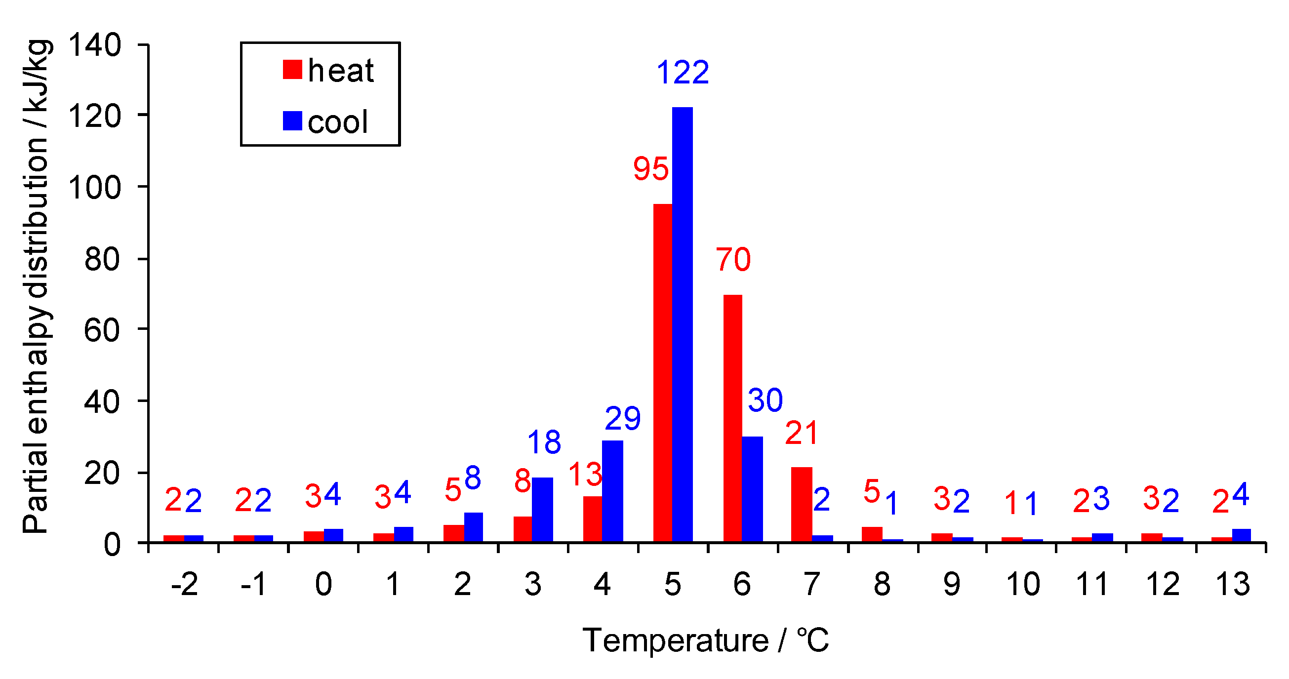
Figure 4.
Heat transfer schema of the cold-chain insulated container at a high ambient temperature. VIP: vacuum insulation panel; PU: polyurethane.
Figure 4.
Heat transfer schema of the cold-chain insulated container at a high ambient temperature. VIP: vacuum insulation panel; PU: polyurethane.

Figure 5.
Arrangement of the temperature measuring points.
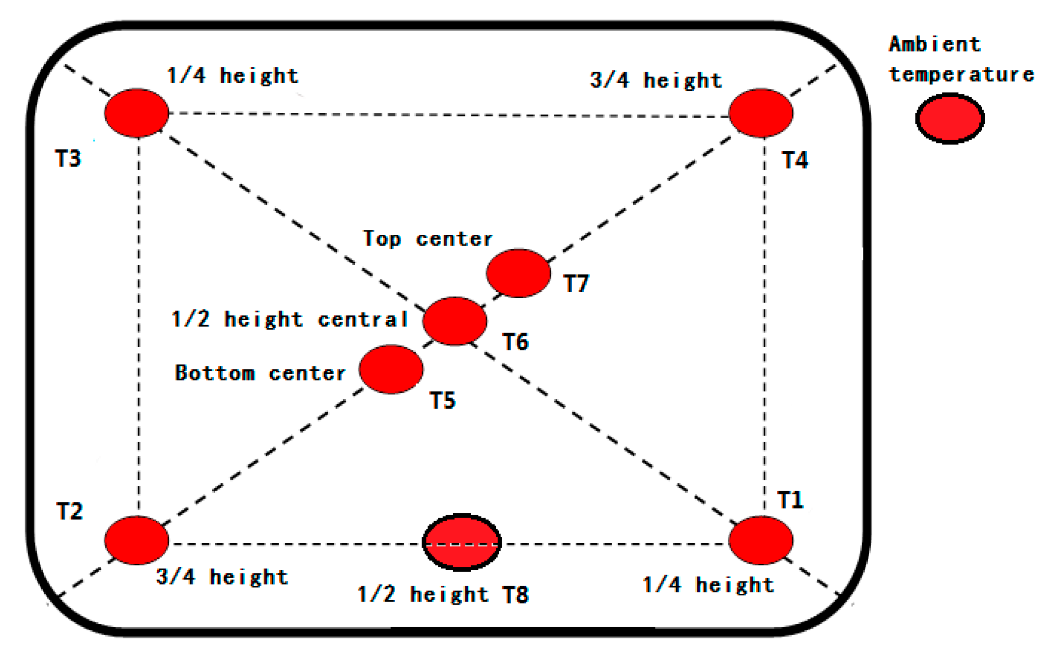
Figure 6.
The ambient temperature and air temperature inside the container without PCM under extremely high temperature condition. The shaded part means the controlled temperature range of 2 to 8 °C.
Figure 6.
The ambient temperature and air temperature inside the container without PCM under extremely high temperature condition. The shaded part means the controlled temperature range of 2 to 8 °C.
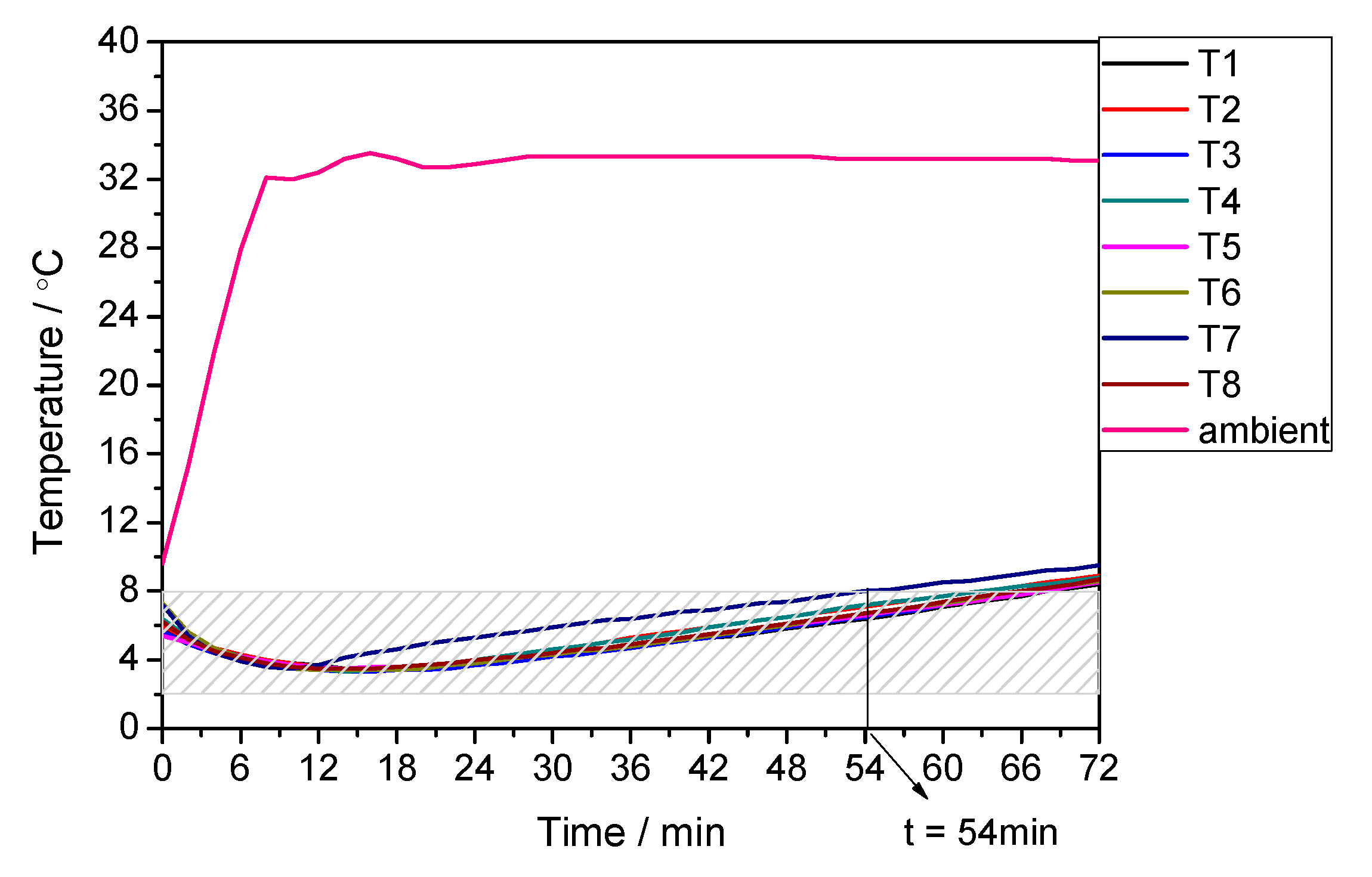
Figure 7.
The ambient temperature and air temperature inside the container with water as PCM under extremely high temperature condition.
Figure 7.
The ambient temperature and air temperature inside the container with water as PCM under extremely high temperature condition.

Figure 8.
The ambient temperature and air temperature inside the container with OP5E as PCM under extremely high temperature condition.
Figure 8.
The ambient temperature and air temperature inside the container with OP5E as PCM under extremely high temperature condition.

Figure 9.
The ambient temperature and air temperature inside the container without PCM under extremely low temperature condition.
Figure 9.
The ambient temperature and air temperature inside the container without PCM under extremely low temperature condition.
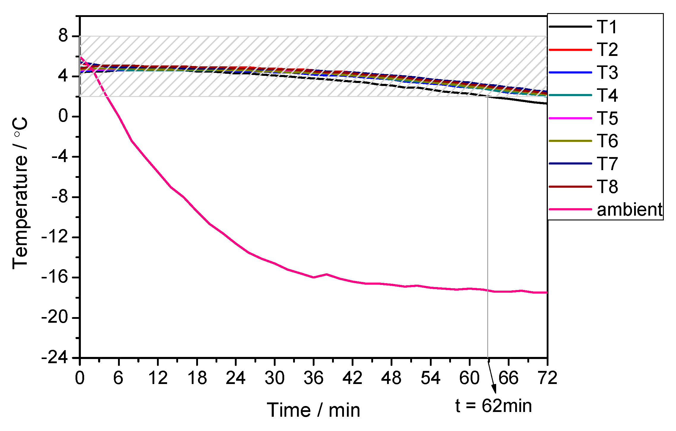
Figure 10.
The ambient temperature and air temperature inside the container with water as PCM under extremely low temperature condition.
Figure 10.
The ambient temperature and air temperature inside the container with water as PCM under extremely low temperature condition.

Figure 11.
The ambient temperature and air temperature inside the container with OP5E as PCM under extremely low temperature condition.
Figure 11.
The ambient temperature and air temperature inside the container with OP5E as PCM under extremely low temperature condition.

Figure 12.
The ambient temperature and air temperature inside the container with water as PCM under alternating temperature condition.
Figure 12.
The ambient temperature and air temperature inside the container with water as PCM under alternating temperature condition.

Figure 13.
The ambient temperature and air temperature inside the container with OP5E as PCM under alternating temperature condition.
Figure 13.
The ambient temperature and air temperature inside the container with OP5E as PCM under alternating temperature condition.

Table 1.
Technical parameters of water and OP5E. OP5E: an alkane mixture manufactured by Ruhr New Material Technology Co., Ltd. in Hangzhou in China.
Table 1.
Technical parameters of water and OP5E. OP5E: an alkane mixture manufactured by Ruhr New Material Technology Co., Ltd. in Hangzhou in China.
| Parameter | Water | OP5E |
|---|---|---|
| Specific heat capacity/kJ/(kg·K) | 4.2 | 2.0 |
| Solid density (−15 °C)/kg/L | 0.996 | 0.88 |
| Liquid density (20 °C)/kg/L | 0.998 | 0.76 |
| Thermal conductivity liquid/W/(m·K) | 0.56 | 0.2 |
| Volume expansion/% | 0.3 | 13 |
| Total mass used in the container (kg) | 10.87 | 8.28 |
Table 2.
The experimental and theoretical values of the temperature-controlled time of the container with OP5E as PCM under different temperature conditions.
Table 2.
The experimental and theoretical values of the temperature-controlled time of the container with OP5E as PCM under different temperature conditions.
| Ambient Temperature (°C) | Maximum or Minimum Temperature Allowed in the Container (°C) | Temperature-Controlled Time (h) | Deviation (%) | |
|---|---|---|---|---|
| Experimental | Theoretical | |||
| 35 | 8 | 81 | 88 | −7.95 |
| −20 | 2 | 102 | 108 | −5.56 |
| 35 °C for the first 48 h and −20 °C for rest time | 8 °C for the first 48 h and 2 °C for the rest time | 100 | 98 | +2.04 |
© 2017 by the authors. Licensee MDPI, Basel, Switzerland. This article is an open access article distributed under the terms and conditions of the Creative Commons Attribution (CC BY) license (http://creativecommons.org/licenses/by/4.0/).
Share and Cite
MDPI and ACS Style
Huang, L.; Piontek, U. Improving Performance of Cold-Chain Insulated Container with Phase Change Material: An Experimental Investigation. Appl. Sci. 2017, 7, 1288. https://doi.org/10.3390/app7121288
AMA Style
Huang L, Piontek U. Improving Performance of Cold-Chain Insulated Container with Phase Change Material: An Experimental Investigation. Applied Sciences. 2017; 7(12):1288. https://doi.org/10.3390/app7121288
Chicago/Turabian StyleHuang, Li, and Udo Piontek. 2017. "Improving Performance of Cold-Chain Insulated Container with Phase Change Material: An Experimental Investigation" Applied Sciences 7, no. 12: 1288. https://doi.org/10.3390/app7121288
Note that from the first issue of 2016, this journal uses article numbers instead of page numbers. See further details here.