Article

Atmospheric Attenuation Correction Based on a Constant Reference for High-Precision Infrared Radiometry

1
Changchun Institute of Optics, Fine Mechanics and Physics, Chinese Academy of Sciences, Changchun 13033, China
2
University of Chinese Academy of Sciences, Beijing 100049, China
*
Author to whom correspondence should be addressed.
Appl. Sci. 2017, 7(11), 1165; https://doi.org/10.3390/app7111165
Submission received: 11 September 2017 / Revised: 6 November 2017 / Accepted: 9 November 2017 / Published: 13 November 2017

Abstract

:
Infrared (IR) radiometry technology is an important method for characterizing the IR signature of targets, such as aircrafts or rockets. However, the received signal of targets could be reduced by a combination of atmospheric molecule absorption and aerosol scattering. Therefore, atmospheric correction is a requisite step for obtaining the real radiance of targets. Conventionally, the atmospheric transmittance and the air path radiance are calculated by an atmospheric radiative transfer calculation software. In this paper, an improved IR radiometric method based on constant reference correction of atmospheric attenuation is proposed. The basic principle and procedure of this method are introduced, and then the linear model of high-speed calibration in consideration of the integration time is employed and confirmed, which is then applicable in various complex conditions. To eliminate stochastic errors, radiometric experiments were conducted for multiple integration times. Finally, several experiments were performed on a mid-wave IR system with Φ600 mm aperture. The radiometry results indicate that the radiation inversion precision of the novel method is 4.78–4.89%, while the precision of the conventional method is 10.86–13.81%.

1. Introduction

With the development of IR detectors and radiometry technology, ground-based IR radiometric systems have become attractive, as they have the advantage of higher atmospheric transmittance compared with visible systems, and passive measurement can be used to hide the measurement systems. On the one hand, they are widely used for imaging and observation of the characteristics of military and scientific objects, on the other hand, radiometry technology tends to be topical for obtaining the infrared characteristics of targets at distances of tens or hundreds of kilometers. With this sort of study and application, infrared radiometric systems often require calibration against a blackbody near the entrance pupil. In fact, the discrepancy between calibration and actual radiometry in the outfield can create significant radiometric errors unless the attenuation is accurately taken into account [1,2].
The air is opaque to certain IR wavelengths and transparent to others. For example, the visible spectrum band (0.4–0.75 μm) is almost uniformly transparent. However, for IR light, there is a complicated atmospheric transmission curve, with many narrow absorption bands due to molecular resonances. The 3–5 μm window, namely mid-wave infrared (MWIR), is one of the most commonly used bands in infrared radiometry technology for long-range observation and target recognition [3]. The MWIR spans an atmospheric window with very strong absorption bands due to water (H2O) and carbon dioxide (CO2). As is shown in Figure 1, there is a strong CO2 absorption band within the 3–5 μm window at around 4.2–4.4 μm, marked with a red line [4]. For high-precision radiometry, it has a noticeable effect. Therefore, it is desirable to correct the atmospheric transmission for target signature radiometry and recognition. The air force atmospheric laboratory has been working on global atmospheric research, and is one of the earliest scientific research institutes to carry out atmospheric study. Some scholars, such as Yin, conducted infrared radiometry on the sea surface [5], Wei has developed software for atmospheric correction [6], and Han has studied the effect of atmosphere transmission on IR radiation features of targets and backgrounds [7]. When involving infrared radiometry, the effect of the atmospheric transmittance and the air path radiance cannot be disregarded.
At present, the process of IR radiometry and the acquisition of atmospheric transmission are conducted simultaneously, so the radiance could be revised for each frame. In the conventional radiometric method, it is necessary to measure atmospheric parameters with suitable devices and calculate the atmospheric transmittance and air path radiance from these parameters by atmospheric radiation transport calculation software, such as MODTRAN (MODTRAN4.0, Ontar Corporation, North Andover, MA, USA, 2004) [8]. Even so, the error of the atmospheric transmittance at a high-pitch angles (usually more than 30°) obtained by software is about 10–20%; even worse, the data in the horizontal direction and low pitch-angle are unreliable. Further investigation of the method for atmospheric transmission is desirable to improve the precision of radiometry [9,10,11].
In this article, to adjust the efficiency of IR radiometric calibration in the outfield, a model of high-speed calibration considering integration time is employed in Section 2. Following this, a radiometric method based on a constant reference to amend atmospheric transmission for high-precision radiometry is proposed in Section 3. Afterwards, calibration and radiometric experiments based on a MWIR system with a Φ600 mm diameter are carried out to verify the theories described above in Section 2 and Section 3. It is concluded, in Section 4, that our method yields high precision while allowing the user to perform radiometry without atmospheric radiative transfer calculation software. Additionally, it improves the flexibility and efficiency of radiometry.

2. High Dynamic Infrared (IR) Radiometry Based on a Constant Reference

2.1. High-Speed Calibration

Radiometric calibration of an IR system is essential to accurately determine the target’s radiance or temperature. In the outfield, it is worthy of an infrared radiometric system to provide high mobility and efficiency. Hence, the extended blackbody calibration method is adopted, which is suitable for large-aperture IR systems. The pattern of this method for a large aperture system is displayed in Figure 2. Additionally, IR radiometric systems are generally operated in a high dynamic range of irradiance. The alteration of the integration time could increase the dynamic range. The trouble with conventional calibration is that it has to be conducted at every integration time, which is time-consuming [12]. In order to meet high-dynamic range requirements in radiometric applications, the IR imaging systems are usually calibrated at different integration times; therefore, the model of high-speed calibration that includes the integration time can be described as:
G i , j = t ( R i , j ε L ( T ) + G o u t ) + G i n
where G i , j is the gray value of the ( i , j ) th detector in the array, and, t is the integration time in units of ms, R i , j is the normalized radiation flux response, ε is the emissivity of the calibration source, L(T) is the radiance of a blackbody at temperature T, G o u t is the offset caused by the ambient temperature, and G i n is the offset caused by internal factors.
( t 1 ε L ( T 1 ) t 1 1 t 2 ε L ( T 1 ) t 2 1 t 2 ε L ( T 2 ) t 2 1 ) ( R i , j G o u t G i n ) = ( G i , j ( t 1 , T 1 ) G i , j ( t 2 , T 1 ) G i , j ( t 2 , T 2 ) )
( R i , j G o u t G i n ) = ( t 1 L ( T 1 ) t 1 1 t 2 L ( T 1 ) t 2 1 t 2 L ( T 2 ) t 2 1 ) 1 ( G i , j ( t 1 , T 1 ) G i , j ( t 2 , T 1 ) G i , j ( t 2 , T 2 ) )
From Equation (1), we can see that the gray value is linear with the integration time and radiance. Hence, once the integration time and the temperature have been obtained, the calibration result at a random integration time may be calculated from Equation (3) by high-speed calibration that includes the integration time:
The observed targets are detected in the outfield in a large range of IR radiances; therefore, it is vital that the IR systems have the same high dynamic range, in order to detect the overall information of targets. Therefore, several different integration times are selected to avoid saturation of the detector. Thus, the output gray value of the detector pixel can be expressed as:
G i , j = t ( τ a t m R i , j ε 2 L ( T 0 ) + R i , j L p a t h + G o u t ) + G i n
where ε 2 is the emissivity of the target, τ a t m is the atmospheric transmittance, T 0 is the surface temperature of target, t is the integration time, R i , j is the normalized radiation flux response, G o u t is the offset caused by ambient temperature related with t, G i n is the offset caused by internal factors unrelated with t, and L p a t h denotes the path radiance.
The radiance of the target can be calculated by:
L ( T 0 ) = ( G i , j G i n ) t R i , j L p a t h G o u t ε 2 τ a t m R i , j
where R i , j , G o u t and G i n can be determined by high-speed calibration as proposed above in this paper.

2.2. Atmospheric Transmittance Correction Based on a Constant Reference

In Equation (5), τ a t m and L p a t h can be obtained by atmospheric transmittance calculation software such as MODTRAN4.0 and CART (Anhui Institue of Optics and Fine Mechanics, Anhui, Anhui, 2009) [13]. Under general conditions, the multiband radiometer can measure the profile of aerosols and an automatic meteorological data logger can provide data of visibility, temperature, and humidity [14,15,16]. Considering this, MODTRAN4.0 computes the transmittance of the spectrum with a spectral resolution of 1 cm−1 and CART the local atmosphere, then the average transmittance can be acquired with the combination of the two models under the operating band [17]. It is observed that the measurement of the transmittance by software is indirect [18]. Sometimes, the accuracy of this method can hardly be guaranteed.
To further improve the accuracy of IR radiometry, a novel method by which the atmospheric transmittance could be acquired directly is proposed.
The target emits radiation: (1) some of it is absorbed by the atmosphere τ a b s ; (2) another part passes through the atmosphere τ a t m ; and (3) a last portion is scattered by atmosphere τ s c a t . Thus:
τ a t m + τ a b s + τ s c a t = 1
where τ a b s is the ratio of absorption, and τ s c a t is the ratio of scatter.
In the pure atmosphere, aerosols can be ignored in the horizontal direction and at low angles of pitch; especially, for the transmission of IR radiation, the scatter is minimal compared with the transmittance and absorption [19]. Thus, L p a t h can be expressed as:
L p a t h = ( 1 τ a t m ) L ( T e )
where Te, is the ambient temperature. Suppose that the reference is characteristic of uniformity and has a fixed temperature Tm.
Therefore, the atmospheric transmittance τ a t m can be obtained according to Equations (5) and (7) as:
τ a t m = ( G i , j ( T m ) G in ) t G out R i , j L path R i , j ε L ( T m )
Equation (8) states that if a standard radiance has been available, the transmittance could be easily obtained. Therefore, atmospheric transmittance correction based on a constant reference for high precision and wide dynamic IR radiometry is proposed in this study. This method is part of the direct measurement, which has the characteristic of high accuracy. Compared with the method by a standard blackbody as a reference, our method only takes advantage of a constant reference; thus, it is fit for the requirements of IR radiometry in the outfield

3. Experimental Results

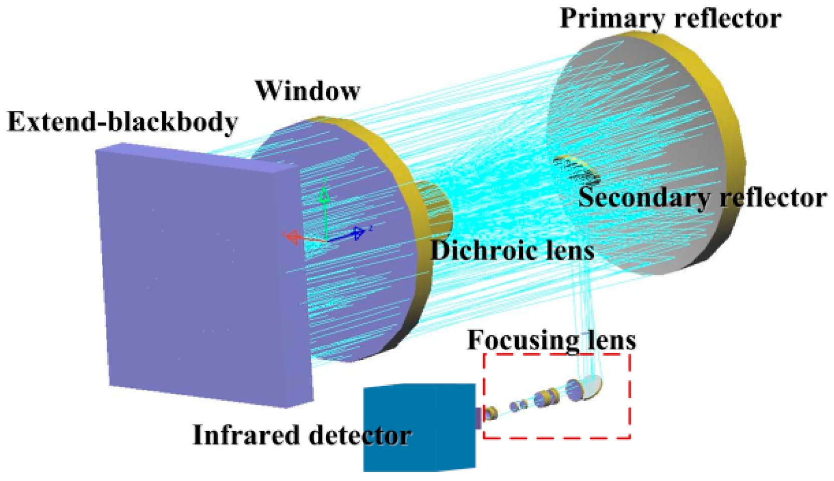
3.1. Experimental Setup

To verify the feasibility of this method, a verification experiment was carried out. The infrared detector operates in the 3–5 μm waveband, and it is composed of 640 × 512 pixels with a 14-bit digital output. The system has a diameter of 600 mm and a focal length of 1200 mm. The calibration source’s emissivity is 0.97, and the temperature range is 0–125 °C.

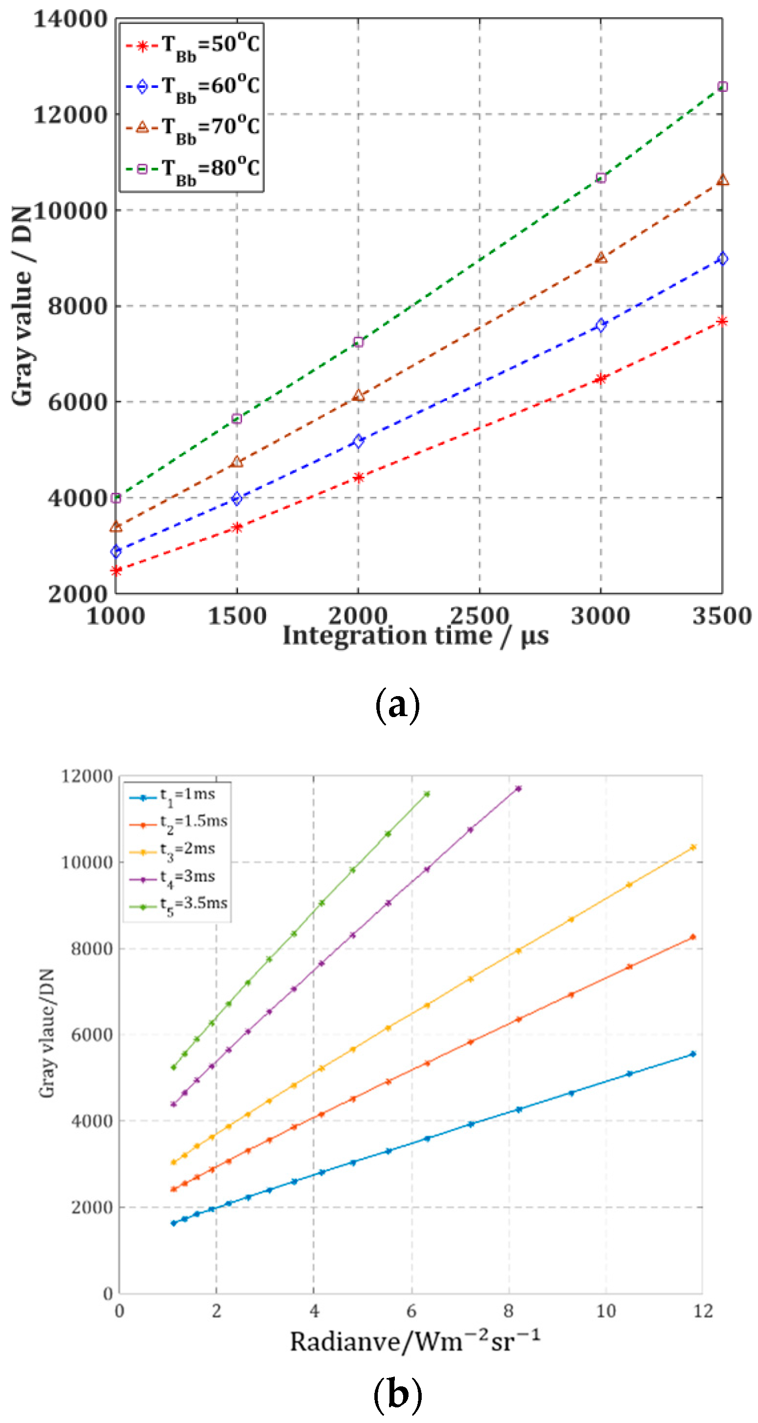
3.2. High-Speed Calibration

As is illustrated in Figure 3a, when the temperature of the extended blackbody is constant, the gray value is linear with the integration time. Additionally, the responsivity increases with the rising temperature of the blackbody. As is shown in Figure 3b, the gray value is linear to the radiance. Additionally, the responsivity increases when the integration time rises.
The calibration equation can be obtained from Equation (2).
y = t × (341.65 × L(T) + 1060.7) + 137.5
The calibration results at integration times of 1500, 2000, and 3000 μs were obtained by Equation (7), and then compared with the standard ones. The errors are shown in Figure 4. The temperatures of the blackbody vary from 20 to 100 °C at an interval of 20 °C. The maximum error between the actual calibration results and calculated results is 1.40% and the calibration error of the system is 0.63%, which demonstrates that the high-speed calibration method ensures the accuracy of the radiometric calibration. Therefore, the high-speed calibration method is valid for IR imaging systems to improve the efficiency of radiometric calibration.

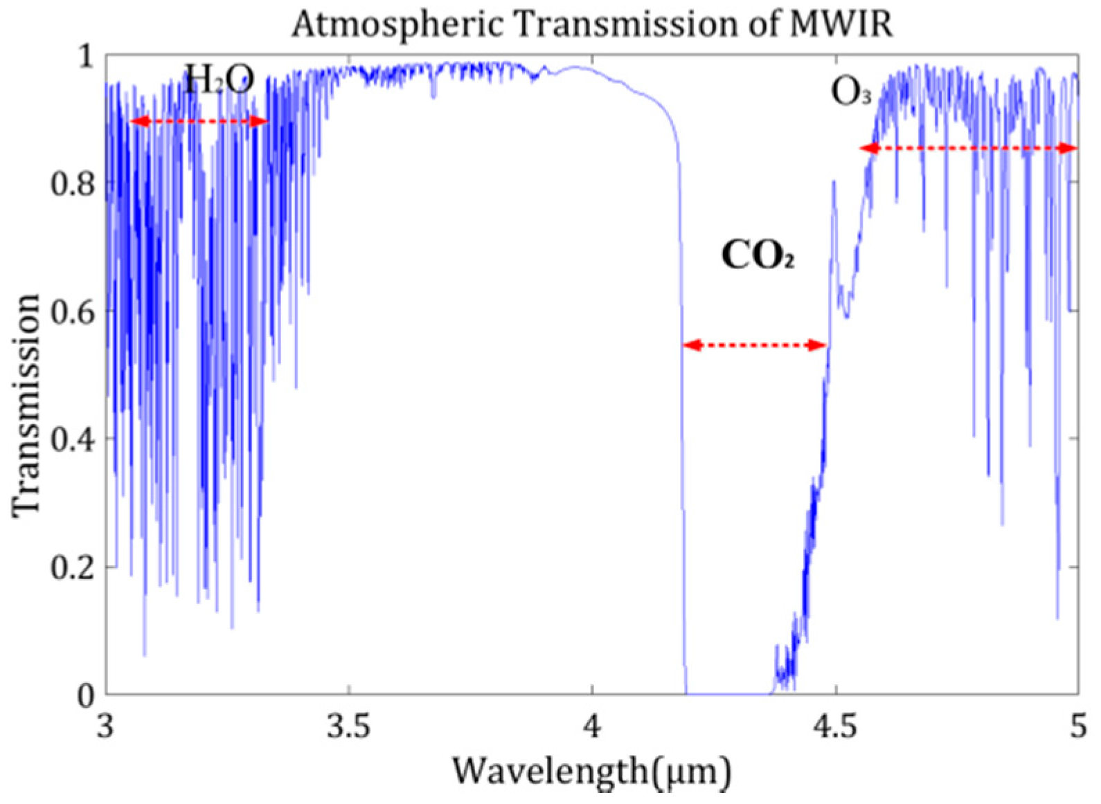
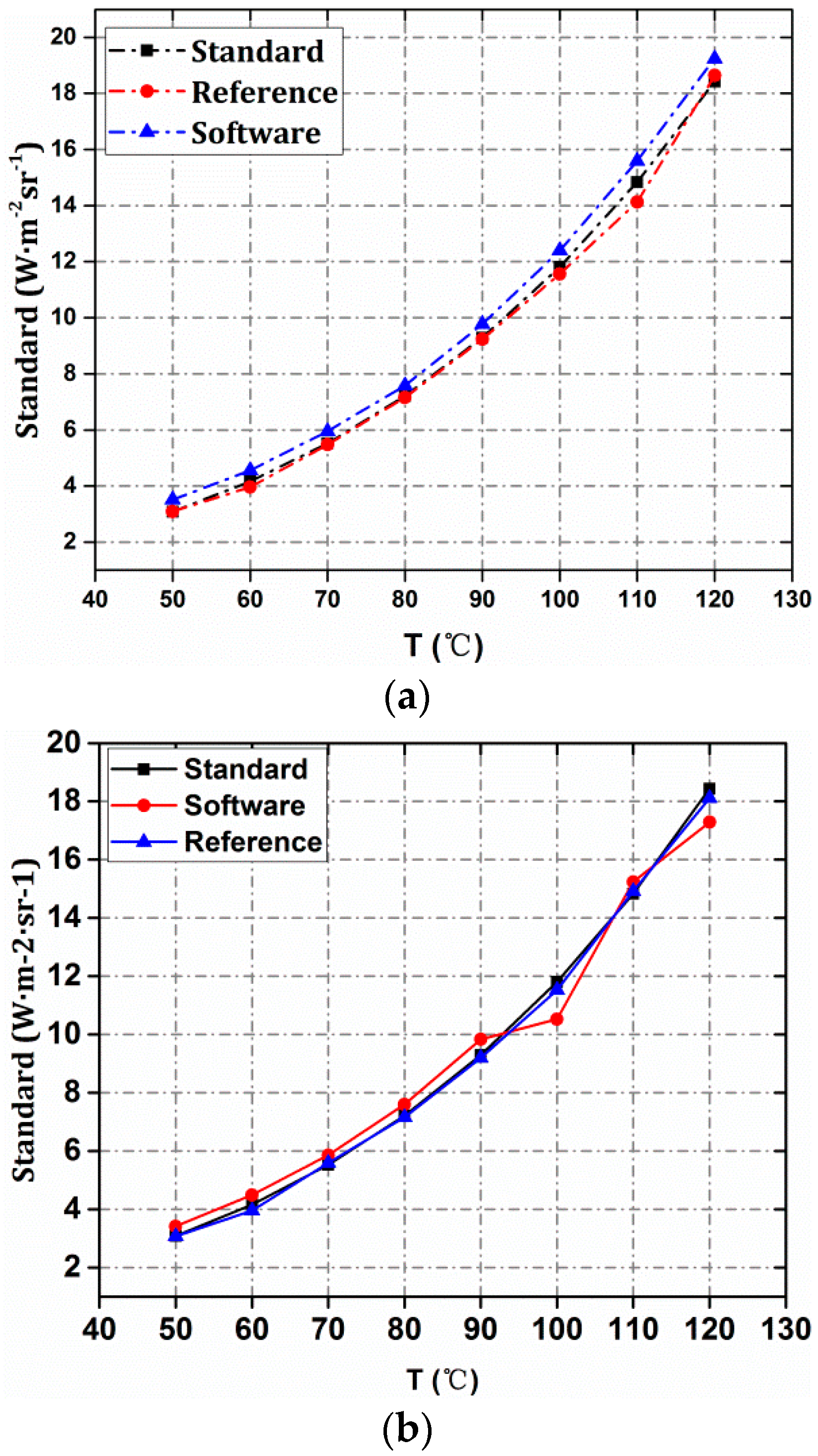
3.3. Atmospheric Transmittance Calculation

In the conventional method, the atmospheric transmittance is calculated with software. CART [20] software is used for atmosphere transmittance correction in this radiometry. During the experiment, the ground average temperature was about 7.5 °C, the pressure was about 856 hPa, the relative humidity was about 20%, the angle of pitch was 0°, the altitude was 1400 m, and the visibility was about 23 km. The distance from the system to the target was 830 m. The average atmospheric transmittance in waveband 3–5 μm was τ a t m 1 = 0.7399 , which was calculated by MODTRAN4.0 using the above-measured parameters, and the path radiance.
L p a t h 1 = 0.1942 W m 2 sr 1
In this paper, as the temperature of ambience was about 7.5 °C and the radiance was L ( T e ) = 0.6884, the path radiance can be expressed from Equation (7) as:
L p a t h = ( 1 τ a t m 2 ) L ( T e ) = ( 1 τ a t m 2 ) 0.6884
The temperature of the reference was 36 °C and the radiance was 1.966 W m 2 sr 1 near the target. To reduce the error, the image obtained at different integration times 2000, 3000, and 3500 μs were employed, and the results are shown in Table 1.
From Table 1, we can see that the radiance distribution of the reference is uniform and stable, so there was a steady transmittance. The average of the atmospheric transmittance was 0.7977. G/DN, Response gray value of infrared detector.

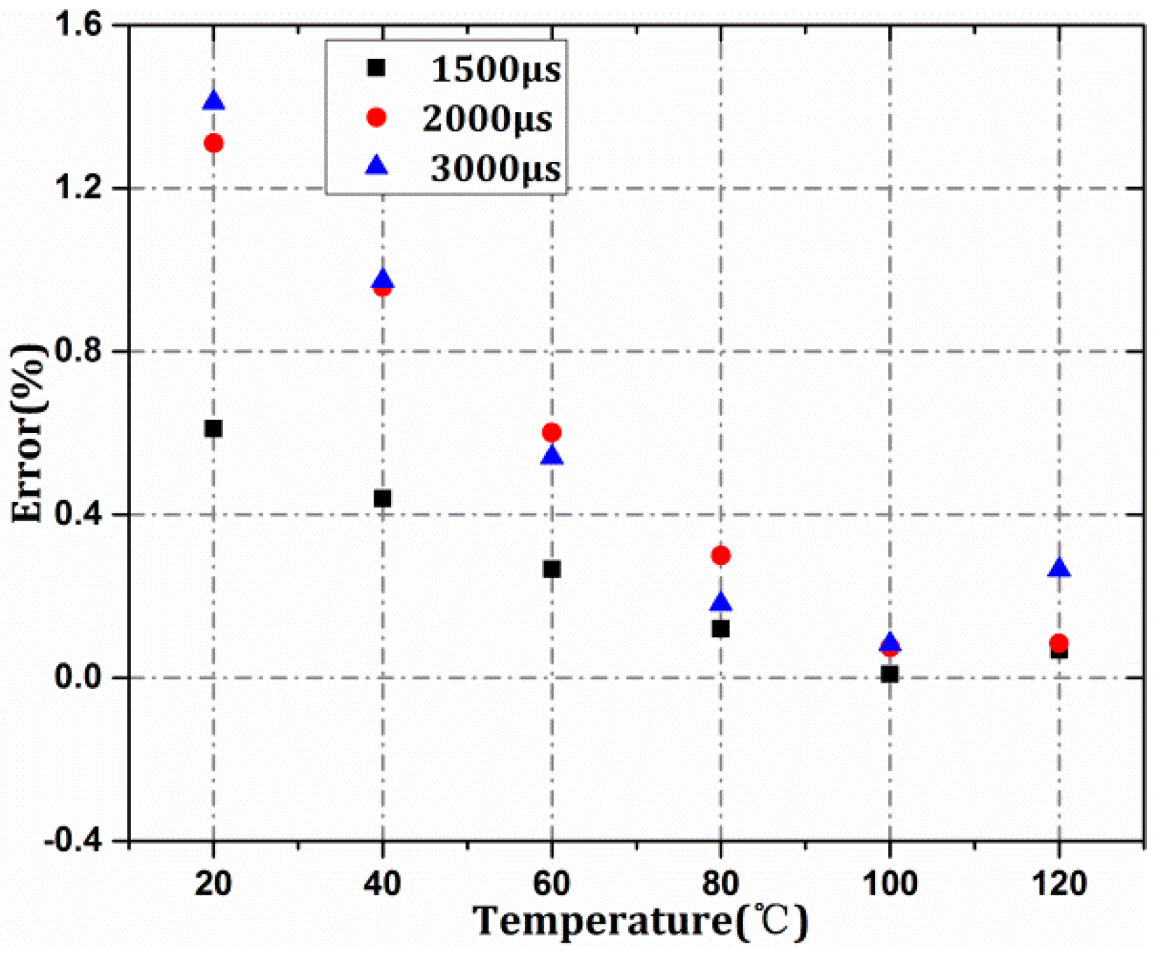
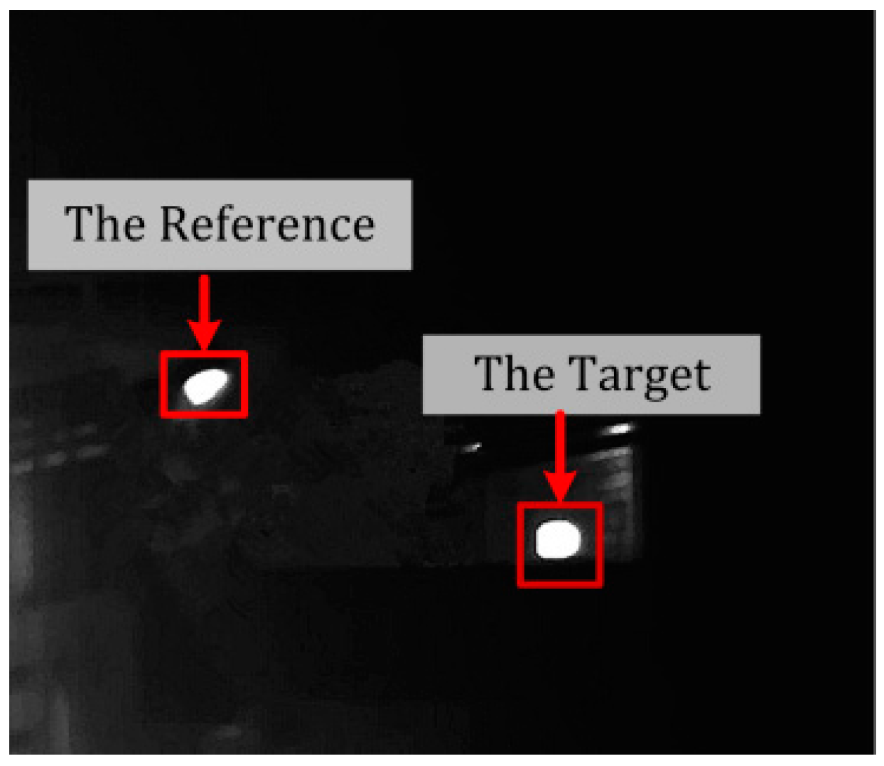
3.4. Radiometry of an IR Target

Images of the targets at temperatures from 20 to 100 °C at an interval of 20 °C were collected, and the integration time of the infrared imaging system was set to 2000 and 3000 μs. The gray image of the target at a distance of 830 m is shown in Figure 5.
Figure 6a,b shows the radiometric results at 2000 and 3000 μs in the outfield, respectively. The blue lines represent the radiation inversion result of the atmospheric transmittance correction MODTRAN. The black lines represent the radiation inversion by Planck’s formula with the correction of the spectrum. The red lines represent the radiation inversion by the method proposed in this paper. The x-axis is the corresponding temperature of target from 50 to 120 °C at intervals of 10 °C and the leftmost y-axis is the radiance of the target.
As shown in Figure 6 and Table 2, the results calculated by MODTRAN4.0 at 2000 μs show that the maximum error was 13.81% and the average error was 7.00%; on the whole, the system error of the root mean square (RMS) was 7.63%. The results using the proposed method demonstrate that the maximum error was 4.78% and the average error was 1.92%, the RMS of the system error is 2.67% at 2000 μs.
Similarly, at 3000μs, the results by software show that the maximum error was 10.86%, the average error was 6.94%, and the RMS of the system error was 7.41%. In contrast, the results by the constant reference show that the maximum error was 4.89% and the average error was 1.15%; and the RMS of the system error was only 2.12%.
Both integration time experiments reveal that the method based on constant references is more accurate for atmospheric inversion than the method based by software. The error tends to be moderate in the range of 50° to 120° at any random integration time.

4. Conclusions

This paper introduces an approach for revising atmospheric transmittance for high-precision and wide-dynamic IR radiometry. The effect of the atmosphere on IR radiometry has been analyzed, and a model of high-speed calibration considering integration times suitable for the outfield employed; therefore, the calibration equation at random integration times was able to be deduced immediately [21,22].
Then, based on ambient temperature and constant reference, an approach to calculating the atmospheric transmittance and the path radiance was proposed. The transmittance was acquired at 2000 and 3000 μs to eliminate stochastic error. Finally, calibration and radiometry experiments were performed based on a MWIR system with Φ600 mm diameter to evaluate whether the proposed method is effective for IR radiometry for even greater precision. The experimental results at 2000 μs and 3000 μs illustrate that the revised method yields high precision: (1) this method remedies the atmospheric transmittance and the path radiance accuracy in horizontal direction and low angle of pitch for high-precision in the outfield; (2) instead of expensive atmospheric observation devices, like laser radar and solar radiometers, it reduces the cost and the complexity of calculations; and (3) the proposed method is able to radiometers, it reduce the atmospheric transmittance and the path radiance in real-time, which makes the result direct, effective, and fit for the outfield. It has to be pointed out that the radiometric results are relevant to the uniformity and invariability of the reference. However, these problems could be solved if a suitable reference is picked up.

Author Contributions

Zhiguo Huang and Jianli Wang conceived the presented idea. Zhiguo Huang and Limei Yin developed the theoretical formalism. Zhiguo Huang and Hongzhuang Li collected and analysed the data. Zhiguo Huang discussed the result and wrote the paper. Jianli Wang supervised the entire work.

Conflicts of Interest

The authors declare no conflict of interest.

References

  1. Chang, S.; Zhu, W.; Sun, Z. Radiometric calibration method for large aperture infrared system with broad dynamic range. Appl. Opt. 2015, 54, 4659–4666. [Google Scholar]
  2. Chang, S.; Li, M.; Sun, Z.; Zhang, Y. Method to remove the effect of ambient temperature on radiometric calibration. Appl. Opt. 2014, 53, 6274–6279. [Google Scholar]
  3. Roney, P.L.; Findlay, F.D.; Blanchard, A.; Cann, M.W.P.; Nicholls, R.W. Atmospheric transmittance in the region near the 4.3-microm band head of CO2. Opt. Lett. 1981, 6, 151–153. [Google Scholar] [CrossRef] [PubMed]
  4. Wei, H.; Chen, X.; Rao, R.; Wang, Y.; Yang, P. A moderate-spectral-resolution transmittance model based on fitting the line-by-line calculation. Opt. Express 2007, 15, 8360–8370. [Google Scholar] [CrossRef] [PubMed]
  5. Yin, X.; Liu, Y.; Wang, Z.; Cheng, Y.; Gu, Y.; Wen, F. Comparison between infrared and microwave radiometers for retrieving the sea surface temperature. Mar. Sci. Bull. 2007, 11, 3–10. [Google Scholar]
  6. Wei, H.L.; Chen, X.H.; Zhan, J.; Rao, R. Atmospheric correction in the measurement of infrared radiance. J. Atmos. Environ. Opt. 2007, 2, 472–478. [Google Scholar]
  7. Han, Y.G.; Xuan, Y.M. Effect of atmospherictransmission on IR radiation feature of target and background. J. Appl. Opt. 2002, 23, 8–11. [Google Scholar]
  8. Acharya, P.K.; Berk, A.; Anderson, G.P.; Larsen, N.F.; Tsay, S.C.; Stamnes, K.H. MODTRAN4: Multiple scattering and bidirectional reflectance distribution function (BRDF) upgrades to MODTRAN. Proc. SPIE Int. Soc. Opt. Eng. 1999, 3756, 354–362. [Google Scholar]
  9. Ochs, M.; Schulz, A.; Bauer, H.J. High dynamic range infrared thermography by pixel wise radiometric self-calibration. Infrared Phys. Technol. 2010, 53, 112–119. [Google Scholar] [CrossRef]
  10. Samantaray, N.; Ruo-berchera, I.; Meda, A.; Genovese, M. Realization of the first sub-shot-noise wide field microscope. Light Sci. Appl. 2017, 6, e17005. [Google Scholar] [CrossRef]
  11. Zhang, T.S.; Liu, W.Q.; Gao, M.G.; Lu, Y.H.; Liu, J.G.; Liu, C.; Xu, L.; Zhu, J. The study of infrared background radiation of earth and atmosphere by airborne FTIR spectrometer. Spectrosc. Spectr. Anal. 2006, 26, 1018–1021. [Google Scholar]
  12. Zhu, J.; Liu, W.Q.; Lu, Y.H. Research on radiance measurements of target and background based on FTIR. Infrared Technol. 2004, 26, 52–55. [Google Scholar]
  13. Wei, H.; Chen, X.; Dai, C. Combined atmospheric radiative transfer (CART) model and its applications. Infrared Laser Eng. 2012, 41, 3360–3366. [Google Scholar]
  14. Richards, A. Atmospheric effects on infrared imaging systems. Proc. SPIE 2005, 5987, 1–14. [Google Scholar] [CrossRef]
  15. Yang, T.; Jin, G.F.; Zhu, J. Automated design of freeform imaging systems. Light Sci. Appl. 2017, 6, e17081. [Google Scholar]
  16. Yan, M.; Luo, P.L.; Iwakuni, K.; Millot, G.; Hänsch, T.W.; Picqué, N. Mid-infrared dual-comb spectroscopy with electro-optic modulators. Light Sci. Appl. 2017, 6, e17076. [Google Scholar] [CrossRef]
  17. Rothman, L.S.; Gordon, I.E.; Babikov, Y.; Barbe, A.; Benner, D.C.; Bernath, P.F.; Birk, M.; Bizzocchi, L.; Boudon, V.; Brown, L.R.; et al. The HITRAN 2012 molecular spectroscopic database. J. Quant. Spectrosc. Radiat. Transf. 2013, 130, 4–50. [Google Scholar] [CrossRef] [Green Version]
  18. Chen, X.; Wei, H. A Combined atmospheric radiative transfer model (CART): A review and applications. J. Opt. Soc. Korea 2010, 14, 190–198. [Google Scholar] [CrossRef]
  19. Wang, W.H.; Niu, Z.D.; Chen, Z.P. Research on the operating range of staring IR imaging system in sea-sky background. J. Infrared Millim. Waves 2006, 25, 150–152. [Google Scholar]
  20. Wei, H.L.; Chen, X.H.; Rao, R.Z. Introduction to the combined atmospheric radiative transfer software CART. J. Atmos. Environ. Opt. 2007, 2, 446–450. [Google Scholar]
  21. Rodrigo, D.; Tittl, A.; Limaj, O.; de Abajo, F.J.G.; Pruneri, V.; Altug, H. Double-layer graphene for enhanced tunable infrared plasmonics. Light Sci. Appl. 2017, 6, e16277. [Google Scholar] [CrossRef]
  22. Xu, Q.; Ma, T.; Danesh, M.; Shivananju, B.N.; Gan, S.; Song, J.; Qiu, C.W.; Cheng, H.M.; Ren, W.; Bao, Q. Effects of edge on graphene plasmons as revealed by infrared nanoimaging. Light Sci. Appl. 2017, 6, e16204. [Google Scholar] [CrossRef] [Green Version]
Figure 1. Atmospheric transmission in the mid-wave infrared (MWIR) region.
Applsci 07 01165 g001
Figure 2. Scheme of near extend-blackbody calibration method.
Applsci 07 01165 g002
Figure 3. The result of high-speed calibration considering the integration time. (a) Output gray value as a function of the integration time; (b) Output gray value as a function of the integration time.
Applsci 07 01165 g003
Figure 4. Errors of high-speed calibration considering the integration time.
Applsci 07 01165 g004
Figure 5. The site of IR radiometry.
Applsci 07 01165 g005
Figure 6. The precison result of radiometry. (a) The comparative result between conventional and the proposed method at 2000 μs; (b) The comparative result between conventional and the proposed method at 3000 μs.
Applsci 07 01165 g006
Table 1. The results of transmittance at different integration times.
t/μs200030003500
G/DN342150735896
τ0.79240.80020.8005
Table 2. The radiometric error at 2000 μs and 3000 μs 1.
2000 μs3000 μs
T/°CError of Software (%)Error of Reference (%)T/°CError of Software (%)Error of Reference (%)
5013.810.275010.730.26
609.574.83607.844.89
707.770.84706.081.23
805.140.78805.310.73
905.190.58905.831.02
1004.962.11100−10.862.41
1105.144.781102.720.56
120RMS4.427.63%1.172.67%120RMS−6.197.41%1.712.12%
1 RMS, root mean square.

