1. Introduction
Rotation angle measurement is essential in a variety of mechanical apparatuses. To achieve precision control for nanometer resolution, optical remote measurements have the advantage of being non-contact, and are easily performed using an optical interferometer. There are various optical methods of precision angle measurement, such as using surface plasmon resonance (SPR), total internal reflection (TIR), Fabry–Perot resonator, white-light interferometry, and imaging displacement sensing [
1,
2,
3,
4,
5,
6,
7,
8,
9]. In optical metrology, the amplitude or phase of a reflected and refracted probe light is dependent on an incident angle in the optical transducer. In the SPR transducer, the amplitude and phase of the reflection
p-wave (electric-field parallel to the incident plane) are abruptly changed at a resonance angle. In contrast, the amplitude and phase of the reflection s-wave (electric-field perpendicular to the incident plane) are only slightly changed. There are two schemes: intensity and phase interrogations, which have been proposed to explore angle measurement. The intensity interrogation approach is simple; however, the reflectance is minimal at the resonance condition. Only a small percentage of the incident photons are detected by the photodetector, which severely reduces the signal-to-noise ratio [
10]. In addition, laser stability is also critical in obtaining precise measurements. In the phase interrogation approach, a common path polarization interferometry has been proposed to overcome the limited resolution resulting from the unstable intensity or weak signal of the probe light. The step-like measured signals can enhance measurement sensitivity, and require precise control of the initial incident angle [
1,
5]. At the same time, the angle scanning range for maintaining a good linear relationship between the measured signal and the angle change is limited. Moreover, gold-film thickness and the probe wavelength are essential for attaining high sensitivity measurements [
1,
2]. In contrast to the SPR transducers, the phase delay of an input with two orthogonal polarizations is dependent on the incident angle while over the critical angle during TIR conditions. The phase curves of the TIR transducers are smoother than those of the SPR measurements. The sensitivity is lower than the SPR, but with a wider range of scanning angles [
4].
It is well known that a birefringent plate (BP) has been widely applied for fabrication of wave plates and polarization splitters [
11]. In addition, nonlinear birefringent crystals such as MgO-doped lithium niobate (MgO:LN) and potassium titanyl phosphate (KTP) are also important for the wavelength converters through nonlinear optics [
12,
13]. Therein, MgO:LN is a uniaxial birefringent crystal with two different refractive indices. KTP is a biaxial birefringent with three different refractive indices. In this paper, we present a new optical angle sensor (OAS) for rotation angle measurement using a birefringent-refraction (BR) transducer performed in a common-path heterodyne interferometer. The OASs were made using the birefringent plates (MgO:LN and KTP) immersed in different liquids. The optical phase delay between two orthogonal polarizations (
p- and
s-wave) of the probe light is dependent on incident angle, the thickness of the birefringent plate and the refractive index (RI) of immersed liquids. In comparison with SPR and TIR transducers [
1,
2,
3,
4,
5,
6], the proposed birefringent-type OAS does not require a precise setting of the specific angle. It can also provide sufficient sensitivity and wide dynamic measurements.
2. Measurement Principles
When the incident light with two orthogonal polarizations passes through the birefringent BPs, the phase delay between them can be measured in the common path polarization interferometry. Phase measurements based on angle scanning methods have been proposed to measure the retardation parameters of the multiple-order wave plate [
14], and the liquid crystal cell parameters (pretilt angle and the cell gap) [
15]. The results of studies measuring retardation parameters show that phase delay is deeply dependent on crystal orientations [
14].
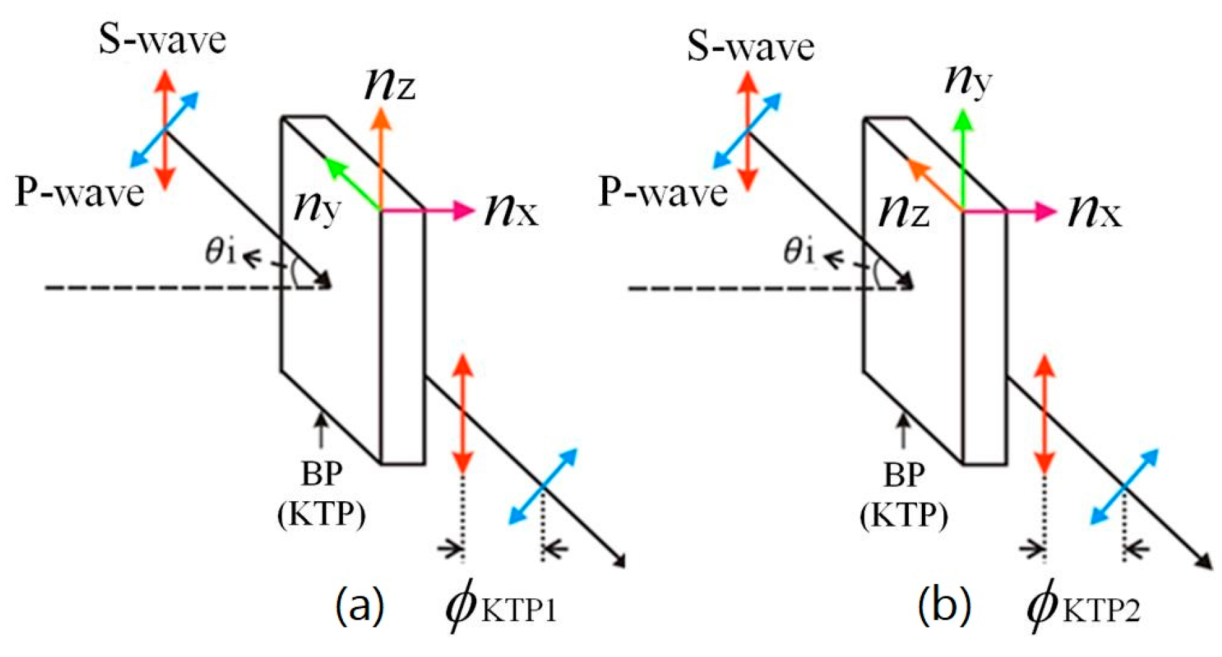
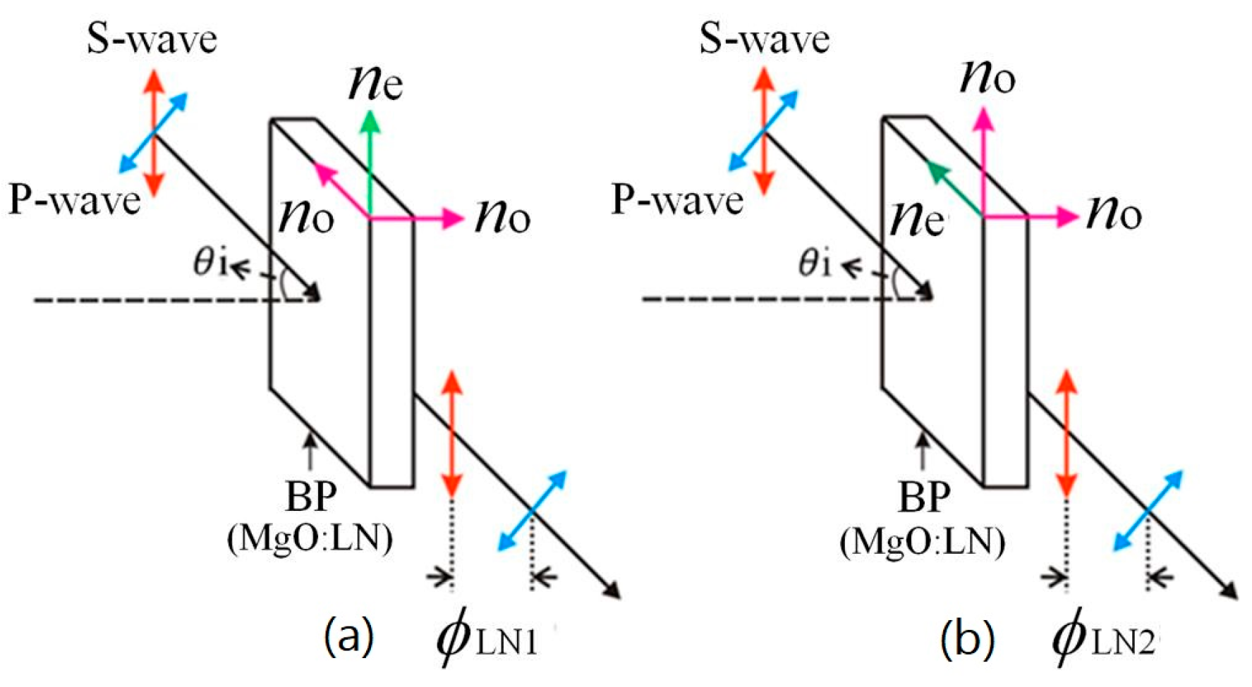
To study the characteristics of the proposed OAS, crystal orientations and the incident polarizations (
s-wave and
p-wave) are schematically shown in
Figure 1 and
Figure 2 for the MgO:LN and the KTP plates, respectively. The
s-wave is parallel to the
ne-axis of MgO:LN and the
nz-axis of KTP, respectively, as shown in
Figure 1a and
Figure 2a. The
s-wave is perpendicular to the
ne-axis and the
nz-axis, as illustrated in
Figure 1b and
Figure 2b.
The corresponding relationships of phase variation and the incident angle are represented by Equations (1)–(4):
where λ is a wavelength of the incident light,
t is a thickness of the BP,
ni is a RI of the immersed medium and θ
i is an incident angle. The refractive indices of extraordinary and ordinary are represented by
ne and
no (
ne = 2.203 and
no = 2.286 at 632.8 nm) in the MgO:LN [
16]. Three different refractive indices,
nx,
ny, and
nz (where
nx = 1.7619,
ny = 1.7712 and
nz = 1.8648 at 632.8 nm), are used for the KPT [
17].
LN1 and
LN2 are the phase variations of the
s-wave applied parallel and perpendicular to the ne-axis of MgO:LN, respectively.
KTP1 and
KTP2 are the phase variations for the
s-wave applied parallel and perpendicular to the
nz-axis of KTP, respectively.
3. Experimental Setup
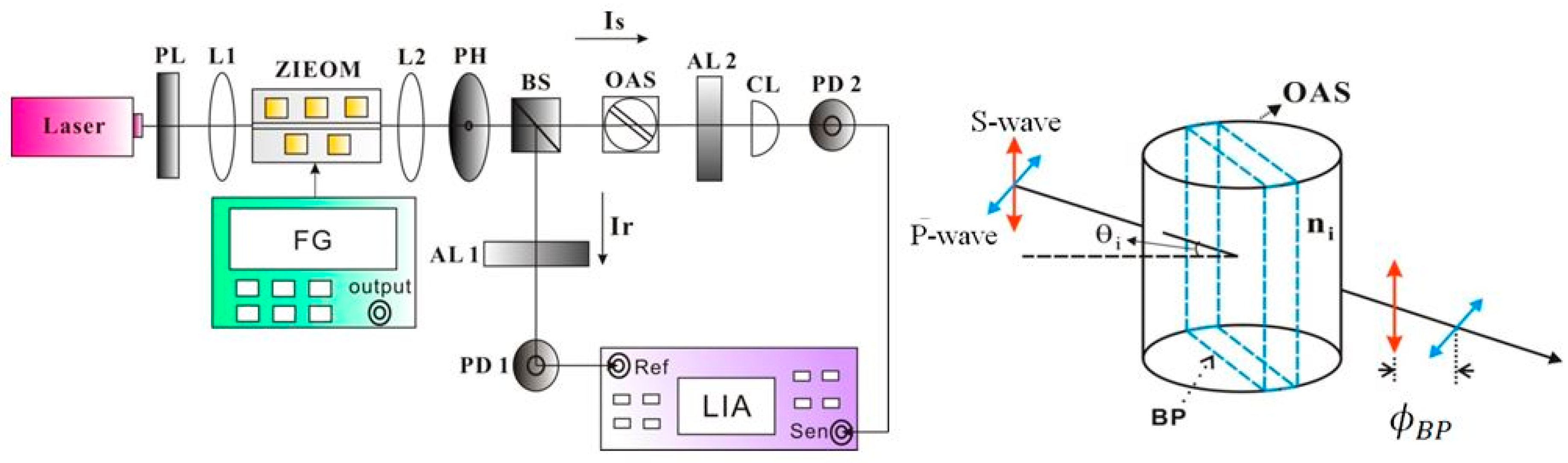
The proposed common-path interferometer for optical angle measurement is shown in
Figure 3. A He-Ne laser with a 632.8 nm wavelength is launched through a polarizer (PL) at 45°. The input light is coupled into a lithium niobate Zn-Indiffused electro-optic modulator (ZIEOM) [
18] through an objective lens (L1). The homemade ZIEOM is a waveguide-type electro-optic device that was fabricated in an
x-cut/
z-propagation lithium niobate substrate. The detailed fabrication process and the applications of heterodyne and homodyne interferometry have been reported in our previous work [
18,
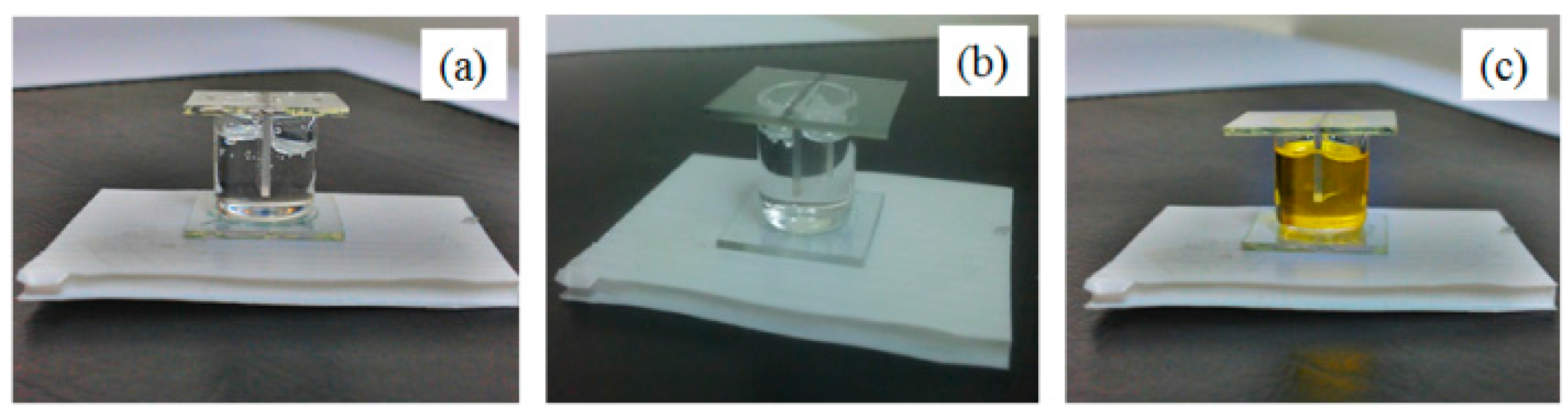
19]. In the heterodyne interferometry, the frequency shifted between two orthogonal lights in the ZIEOM can be generated by applying a prompt sawtooth voltage driven from a function generator (FG). The driving voltage and frequency are 7 V and 100 kHz, respectively. The light is then focused by another lens (L2). A pinhole (PH) is used to block the scattering light. The incident light is divided into two different paths after passing through a beam splitter (BS). The transmitted and reflected paths are used as sensing (Is) and reference (Ir) lights, respectively. The OAS was made using a 1 mm thick BP placed in a cylindrical glass cell filled with different liquids, as shown schematically in the inset of
Figure 3.
Figure 4 illustrates the fabricated OASs with the MgO:LN and KTP plates immersed in different liquids. In the initial development stage, a glass plate is placed directly on the top of the cylindrical glass cell. The covered plate was attached to the glass cell by using a UV curing step. Therefore, the high refractive index liquid can be sealed easily in the cell. The OAS is put on a rotation stage to allow changes in angle. The beam shape after AL2 is focused again, using a cylindrical lens (CL). After passing through two analyzers AL1 and AL2 oriented at 45°, both signals detected by PD1 and PD2 are processed by the lock-in-amplifier (LIA). The phase difference between them can be further extracted for the measurements of angle variations.
4. Results and Discussions
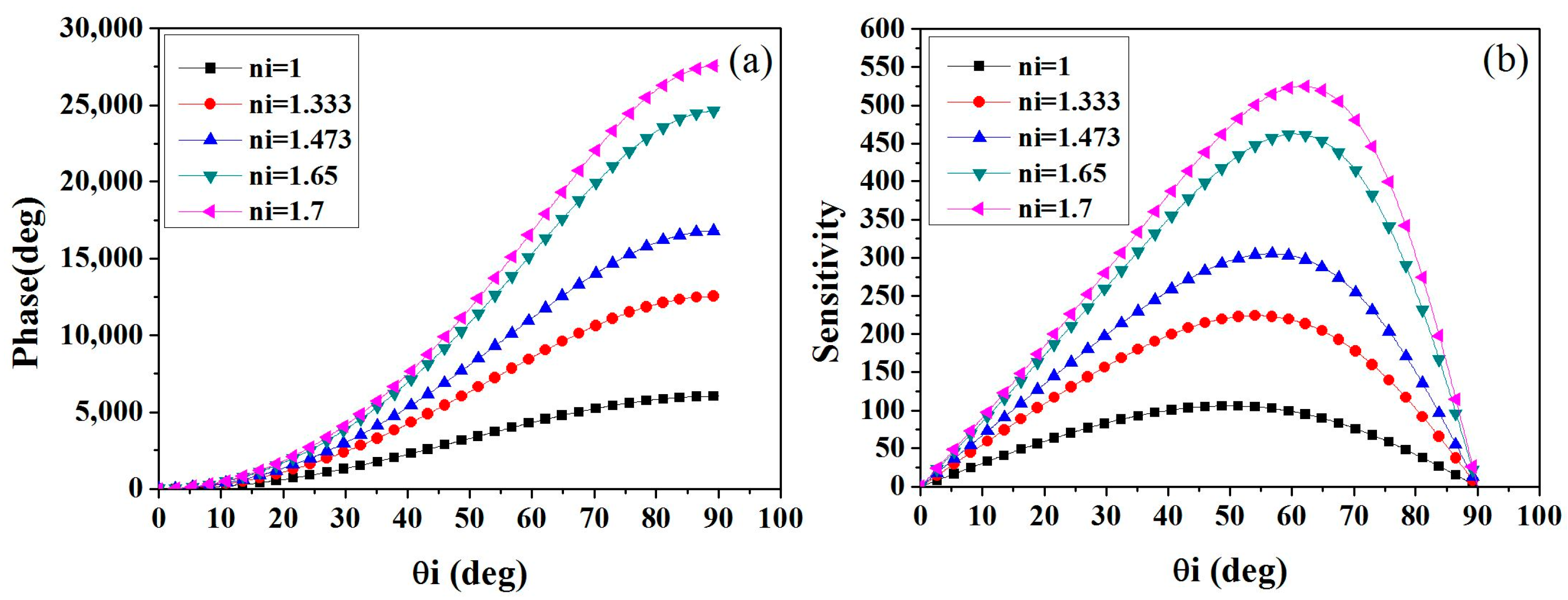
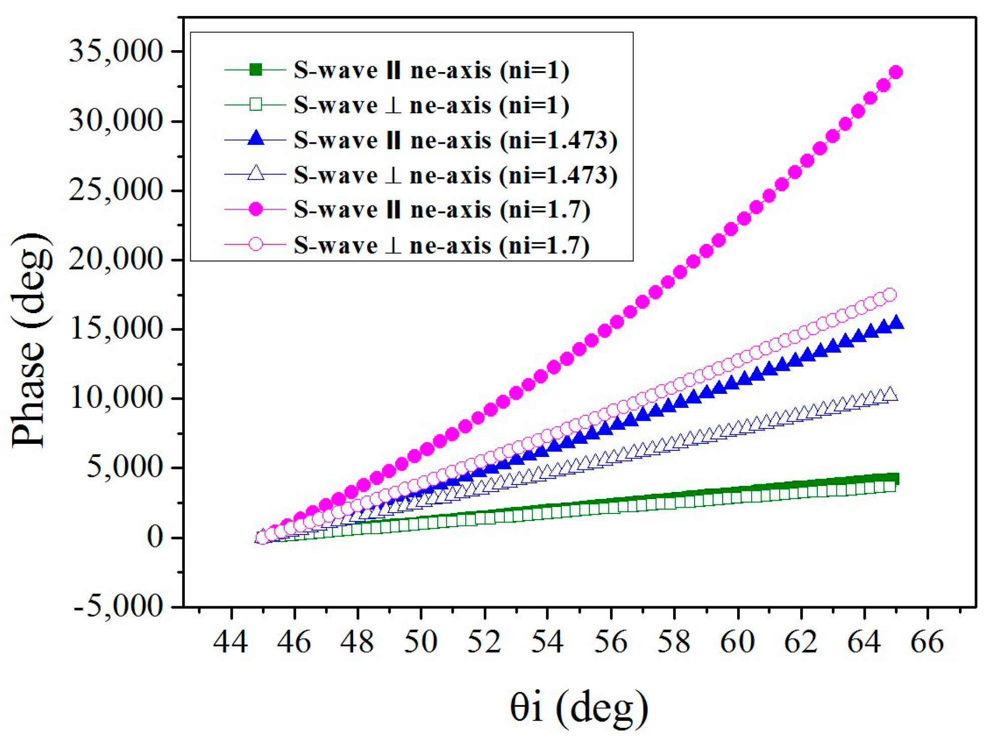
Figure 5 shows the simulation results of phase change versus incident angle for the two crystal orientations and the different RIs of mediums with incident angles ranging from 45° to 65°, according to Equations (1) and (2). The solid and empty symbols of the simulated curves represent the
s-wave parallel and perpendicular to the
ne-axis, respectively.
The results show that in both cases phase changes are increased with a corresponding increase in the RI of the medium with the same crystal orientations. At the same RI, the phase change is higher when the
s-wave is parallel to the
ne-axis of MgO:LN plate. The phase difference between the two crystal orientations (
Figure 1a,b) becomes evident as the RI of the environment is increased. Similar trends are obtained at the KTP plate (not shown), and having the
s-wave parallel to the
nz-axis can also result in higher phase variations. Therefore, it can be concluded that both crystal orientation and the RI of the environment are key parameters in enhancing angle measurement sensitivity.
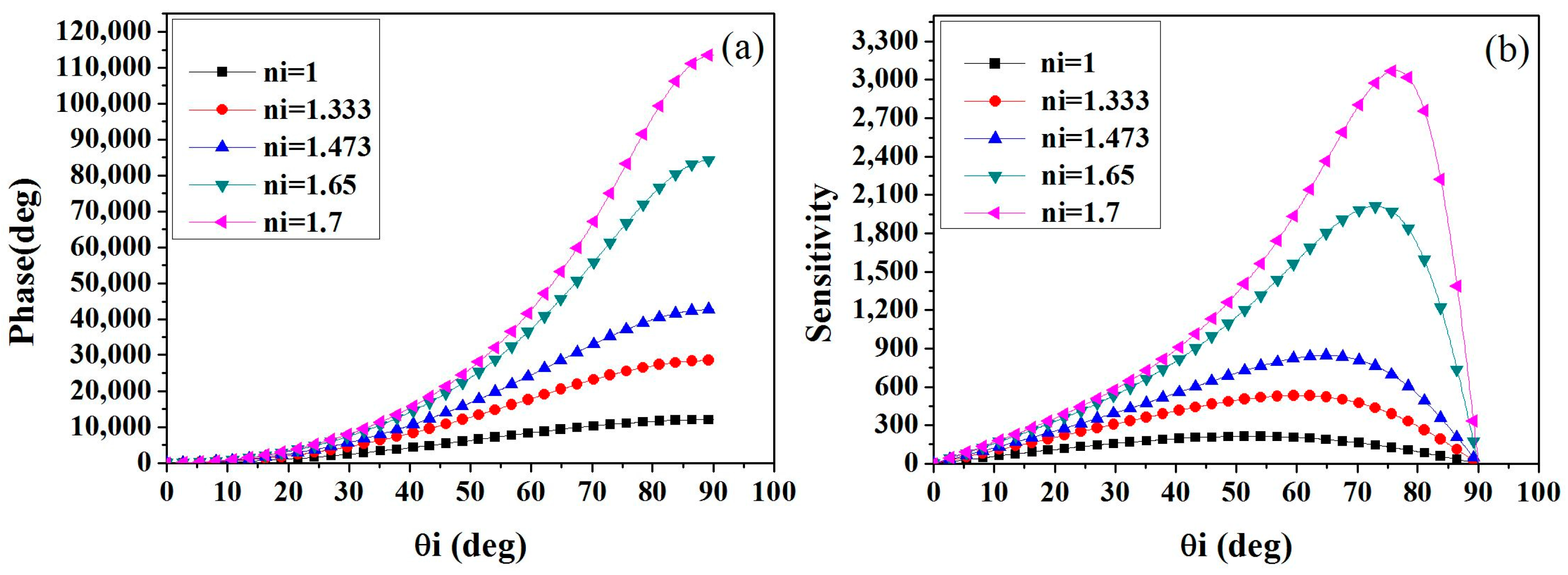
Figure 6a shows the relationships between phase variation and incident angle using various mediums with different RIs for the MgO:LN OAS. The quasi-linear regions of the phase curves are dependent on the incident angle. This indicates that the good linearity between phase change and incident angle has a limited dynamic range. A slope (phase change vs. angle change) is defined as sensitivity, which gradually increases as the RI of mediums in the linear region are increased. Sensitivity versus angle curves are shown in
Figure 6b. The sensitivity curves have maximum values at some specific angles, which in turn are dependent on the RI of mediums. The flattened region of the curves becomes smaller as the RI of mediums is increased. In comparison with the MgO:LN OAS, the phase variation and the sensitivity of the KTP OAS are greatly improved (see
Figure 7). By using the high refractive index oil (
ni = 1.7), the maximum values of sensitivity are 525 and 3072 for the MgO:LN and KTP OASs, respectively.
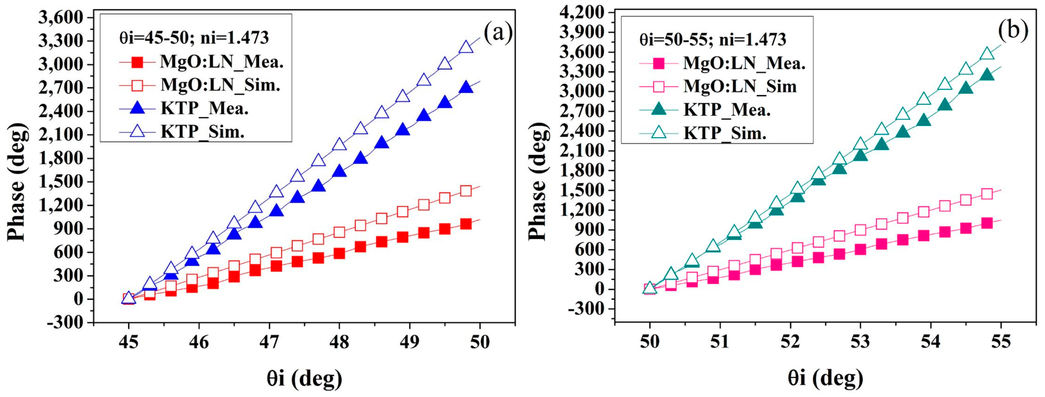
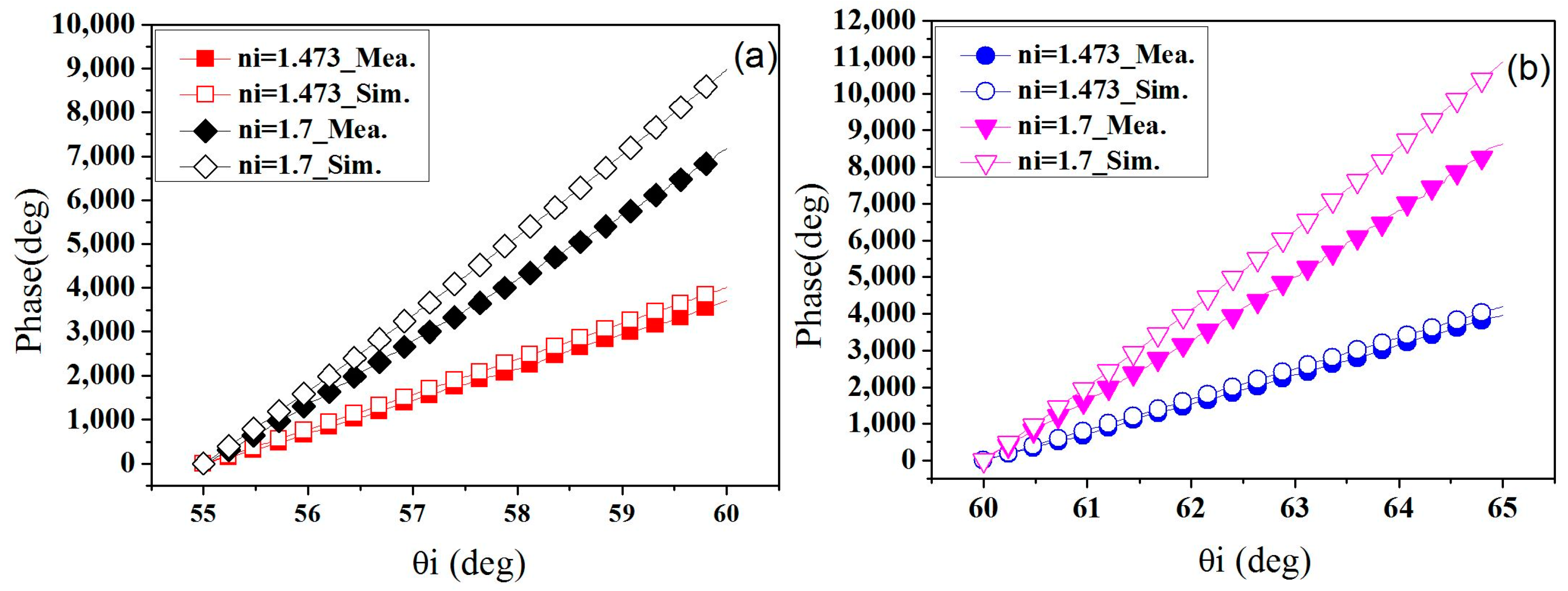
Figure 8 presents the measured results (solid symbol) of phase variation versus incident angle for the MgO:LN and the KTP plates immersed in the glycerin (
ni = 1.473) at different initial angles. By utilizing the MgO:LN plate, the values of measurement sensitivity are about 204 and 209 for the initial angles of 45° and 50°, respectively. In the case of the KTP plate, the sensitivity values are about 557 and 676 for the initial angles of 45° and 50°, respectively. In the simulations (empty symbol), the equations do not consider the cell parameters, including the curvature and refractive index of the cylindrical glass. There is a lens effect that causes the beam overlap difference between two orthogonal polarizations for the different RIs of the mediums. The lens effect is one of the reasons to cause the difference between the simulations and experiments. There are other possible reasons for this difference. According to the specifications provided by the makers, the errors of the thickness and RI of the BPs are less than 1%. These minor errors are not the key factors that cause huge difference. The original RIs of liquids from the makers are used for the simulations. In the experiments, only the RIs of the immersed liquids are possibly different from the expected values due to quality change in stored period. Even if the traces of measurements and simulations are not completely alike, it is obvious that both are still close with good linearity. Actually, the measurements are repeatable in linearity and sensitivity. Especially, the variations of sensitivity are within 0.5% in each measurement under the same conditions. The achievable repeatability and linearity provide the sufficient evidence for the practical use.
Figure 9 shows the measured results of the KTP plate immersed in the glycerin (
ni = 1.473) and the high refractive index oil (
ni = 1.7) using different incident angles. A good linearity is achieved only in the flattened region of the sensitivity curves. In the nonlinear region, the prompt correction factors shall be used to obtain the precision angle measurements based on the phase variation curves. The linearity error is defined as a ratio, half of maximum sensitivity difference versus mean value of sensitivity in the concern angle range. Therefore the linearity error is close to zero in the flattened region of the sensitivity curves. When the KTP plate is immersed in the glycerin, the values of measurement sensitivity are about 742 and 791 for the initial angles of 55° and 60°, respectively. Since the system phase stability is around 0.01°, the average sensitivity of around 766 can provide a measurement resolution of 1.3 × 10
−5 with a wide range of 10° and linearity error of 0.032. By using the high refractive index oil, the values of measurement sensitivity are about 1439 and 1725 for the initial angles of 55° and 60°, respectively. The measurement resolution can be further enhanced to 5.8 × 10
−6 with an angle range of 5° and linearity error of 0.090.
In the simulations, the phase variations only consider the optical path difference between the two orthogonal polarizations. As shown in
Figure 7b, when the environmental RIs of over 1.473, the best incident angles for the highest sensitivity are larger than 65°. In the experiments, the probing beam sizes of
p- and
s-waves are around 0.5 mm in diameter. The refracted angles of the
p- and
s-waves are different in the birefringent crystals. It will enhance walk off between the two orthogonal polarizations in the larger incident angles of over 65°. The experimental results indicate that the reduced overlap between them can further decrease the sensitivity. Therefore, the incident angles smaller than 65° are used for repeatable measurements.
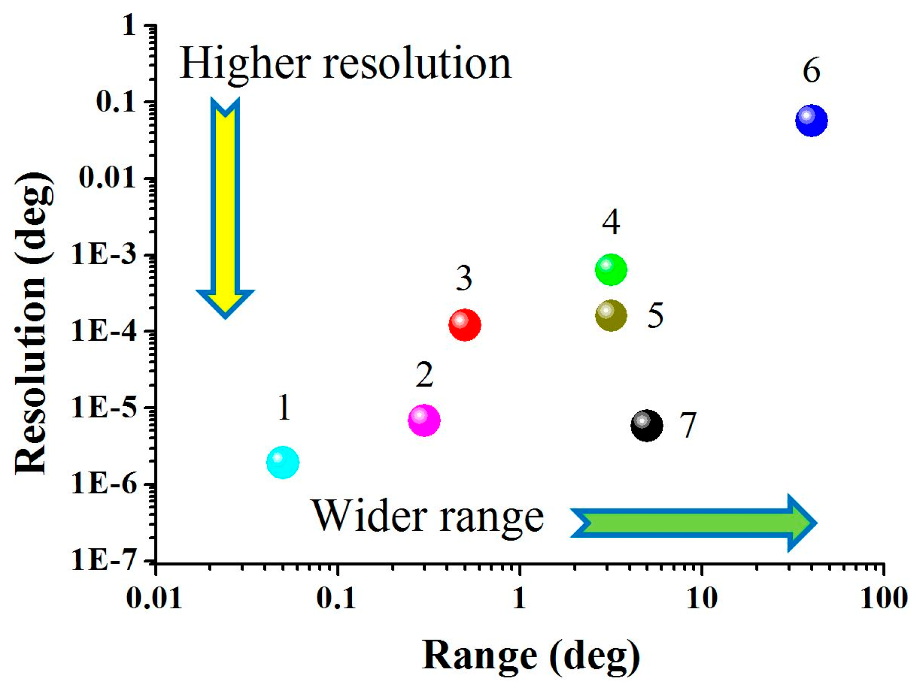
Among the various measurement schemes [
1,
2,
3,
4,
5,
6,
7,
8,
9], the measurement angle ranges and resolutions are all different, and most of the methods have a limited tradeoff relationship between them. It is desirable to have an accurate angle measurement resolution over a wide-angle measurement range. The measurement performance of this proposed birefringent-refraction (BR) methodology will be compared with other methods in the literature. The data of measurement resolution and linear angle range has been summarized and plotted on a performance map as shown in
Figure 10. The horizontal and vertical axes are represented for the range and resolution, respectively. According to the locations of data points on the map, it is clear to see that the SPR sensors (#1 and #2) have the high resolution down to ~10
−6 and narrow linear angle range below 0.3°. The phase-interrogation TIR (#3), Fabry–Perot resonator (#5), and intensity-interrogation TIR close to the critical angle (#4) have the middle resolution of ~10
−4 and middle linear range of 0.3° ~ 3°. The white-light interferometry (#6) provides low resolution of ~10
−1 but wide linear range of 40°. In our results (#7), the proposed BR sensor has the similar high resolution level of ~10
−6 (deg.) achieved in SPR. However, the linear range of 5° is much higher. Especially, the critical angle and SPR sensors always need fine initial angle setting [
1,
6]. In the case of the BR sensor, the tolerance of the initial angle conditions will help the sensing module integrate easily with other elements in the instrument.


