
Complex Fluids in Energy Dissipating Systems


Centro de Estudos de Fenómenos de Transporte, Faculdade de Engenharia da Universidade do Porto, CP 4200-465 Porto, Portugal
Appl. Sci. 2016, 6(8), 206; https://doi.org/10.3390/app6080206
Submission received: 19 May 2016
/
Revised: 4 July 2016
/
Accepted: 15 July 2016
/
Published: 25 July 2016
(This article belongs to the Special Issue Applications of Complex Fluids)
Abstract
:The development of engineered systems for energy dissipation (or absorption) during impacts or vibrations is an increasing need in our society, mainly for human protection applications, but also for ensuring the right performance of different sort of devices, facilities or installations. In the last decade, new energy dissipating composites based on the use of certain complex fluids have flourished, due to their non-linear relationship between stress and strain rate depending on the flow/field configuration. This manuscript intends to review the different approaches reported in the literature, analyses the fundamental physics behind them and assess their pros and cons from the perspective of their practical applications.
Keywords:
complex fluids; electrorheological fluids; ferrofluids; magnetorheological fluids; electro-magneto-rheological fluids; shear thickening fluids; viscoelastic fluids; energy dissipating systemsPACS:
82.70.-y; 83.10.-y; 83.60.-a; 83.80.-k1. Introduction
Preventing damage or discomfort resulting from any sort of external kinetic energy (impact or vibration) is an omnipresent problem in our society. On one hand, impacts and vibrations are responsible for several health problems. According to the European Injury Data Base (IDB), injuries due to accidents are killing one EU citizen every two minutes and disabling many more [1]. Additionally, the European Agency for Safety and Health at Work reported in 2008 that one European worker in three is exposed to vibrations at work and up to 63% of the workers in some sectors such as construction [2]. This can result in Whole Body Vibration (WBV) and Hand-Arm Vibration (HAV) syndromes and vibration-related injuries [3,4]. Many of these impact-related and vibration-related injuries could be prevented or minimized by wearing adequate personal protection equipment, e.g. helmets or anti-vibration gloves [1]. On the other hand, impacts and vibrations can induce malfunctioning in equipment or devices, and its prevention has generated huge and expanding markets. Just to give a couple of examples about its importance, the expected global market revenue of protective cases for smartphones will rise up to US$ ∼25,000 Mn by 2025 [5], while the global market for automotive anti-vibration products, such as engine mounts or dampers, accounted for US$ ∼1,600 Mn in 2013 [6]. Therefore, there is no doubt that developing new advanced energy dissipating systems, able to give the most effective response under external dynamic loads, is an unavoidable global need.
The use of fluid in damping systems is a rather common strategy to turn unwanted kinetic energy into heat energy, which is dissipated through the fluid itself. The classical example given is a hydraulic shock absorber [7], universally employed in automotive vehicles, where the damper is mounted in parallel with the springs to damp the accelerations applied to the frame from the wheel in order to provide a smooth ride. Traditionally, the fluid used in damping systems has been Newtonian, mainly air or oil. A Newtonian fluid provides a linear relationship between stress and strain-rate, being the viscosity of the fluid the constant of proportionality. Thus, as the amount of dissipated energy is proportional to the viscosity of the fluid, once selected a Newtonian fluid, the amount of energy dissipated in the system is determined and limited by the viscosity of the fluid. Then, damping systems using a Newtonian fluid are unable to damp external loads in a selective way. Non-Newtonian fluids offer an opportunity to overcome these limitations and allow enhanced selectivity, either by external field activation or the passive response to critical amplitude (stress or strain-rate) and/or transient timescales (frequencies), as they relationship between stress and strain-rate is non-linear [8]. While the Newtonian fluid dissipates more energy at higher velocity (strain rate), this is a linear relationship between stress and strain-rate. ACTIVE, field-responsive systems can change by many orders of magnitude (e.g., yield stress of magneto-rheological fluids changing by many order of magnitude), even under equivalent forcing conditions. This is clearly selective. Similarly, but less dramatically, shear-thickening and viscoelastic materials also change their stress response by orders of magnitude as a function of amplitude and driving frequency, respectively.
Energy dissipating systems can be understood as isolators. Their final aim is essentially protecting by minimizing displacements or transmitted forces. Within the frame of this publication, and also quite accepted in the literature, an isolation system is considered active if it requires external power supplies (electric or magnetic field), or passive if it does not [9].
In this article, a revision of the state-of-the-art of the main applications of complex fluids in energy dissipating systems is presented. According to the previous distinction, active systems are presented and discussed in Section 2, passive systems in Section 3 and, finally, in Section 4 they are compared, highlighting their pros and cons.
2. Active Systems
The current section is divided in two: Subsection 2.1 reviewing different complex fluids controlled by external field; and Subsection 2.2 showing their different applications in energy dissipating systems.
2.1. Field-Active Fluids
Similarly to the distinction made for isolators, one can distinguish between a fluid requiring an external power to modify its rheological behaviour (field-active fluid) and a fluid able to modify its rheological behaviors just by the action of a mechanical force (passive-field fluids). Within the frame of this section, different field-active fluids will be reviewed. It is worthy to highlight here that, in general, these fluids consist of dispersions of solid particles in a carrier Newtonian fluid. Thus, they ideally exhibit Newtonian behavior at low concentration of particles and without the action of an external field (electric or magnetic). Nevertheless, in practice, the concentration is relatively high and particle interactions may lead to a non-Newtonian behaviour (yield stress), as these particle do not constitute a hard-sphere system. Therefore, they can be strictly considered complex fluids with and without the influence of an external field.
2.1.1. Electrorheological Fluids
Back in 1896, A.W. Duff [10] discovered that the viscosity of certain fluids, like glycerine or castor oil, exhibited a slight reversible change when an electric field was applied perpendicular to the direction of the flow. Active research on electrorheological fluids (ERFs) started in the 1940s, being worldwide recognized through the pioneering work of W.M. Winslow. His patent in 1947 [11] comprised what he termed an electro-fluid clutch, an invention that exploits a novel phenomenon of electricity: “if two plates are separated by certain substantially dielectric fluids containing certain substances the fluid mixture will tend to cause the two plates to act as a unit as long as an electrical potential difference exists between the plates”. Later on, in 1949, he reported the electrorheological phenomena, working with certain suspensions of silica particles in low-viscosity oils. These suspensions exhibited induced shear resistances when bounded by electrodes providing an electric field of the order of 3000 V/mm. He also reported that at low shear stresses, the fluid behaved like a solid, but like a viscous fluid with higher viscosity at larger stresses. The origin of this change in the rheology of these suspensions is in the electrically induced fibration of small particles, that is the tendency to form elongated condensed structures of particles parallel to the field [12]. His research on the electrorheological effect is considered as the origin of the science of electrorheology [13]. Additionally, Wilson also patented a field controlled hydraulic device [14] and improved compositions of the type disclosed in his patent granted in 1947 [15]. For all his contributions, the electrorheological phenomena is also known as the Winslow effect.
Basically, the dielectric or conductivity mismatch between the particles and continuous phase gives place to the electrorheological phenomena. Thus, ERFs consist of particles dispersed in a carrier fluid, where the polarizable components can be either the fluid or the particles. Nevertheless, it is common to find ERFs consisting of colloidal suspensions in which polarizable particles are dispersed in nonpolarizable solvents [16]. ERFs can increase their apparent viscosity by orders of magnitude almost instantaneously upon the application of an electric field, from fluid-like to solid-like, with a yield stress [17,18,19,20,21,22,23,24] characterizing its strength [25]. That microstructural transition, in which the particles form chains connecting the electrodes once the electric field is active, is reversible once the voltage is removed, as depicted in Figure 1. This fast, strong and reversible response allows the development of simple and efficient electromechanical systems able to control vibrations and dissipate energy in shocks [26,27]. However, the development of applications has been hindered due to the weakness of the Electrorheological effect (<10 kPa, much below 30 kPa required by many mechanical devices [28]) until the discovery of the giant electrorheological (GER) effect [29], which can reach a yield strength (>10 kPa [28]) above the theoretical upper bound on conventional ERFs. Additionally, while the static yield stress of ERFs shows a quadratic dependence on the electric field, GER effect exhibits a quasi-linear dependence [30].
2.1.2. Magnetic Fluids
According to Charles [31], magnetic fluids are fluids with magnetic properties and they are conveniently divided into four categories: ferrofluids, magnetorheological fluids, dispersions of micron-sized particles of a non-magnetic material containing magnetic nano-sized particles and fluids containing paramagnetic particles. Due to purely practical reasons, the attention here is focused on Ferrofluids (particle size ≪1 µm) and Magnetorheological fluids (particle size ≥1 µm).
Recently, a new large family of elastomeric materials consisting of a solid polymeric matrix filled with doped polyparaphenylene or carbonyl iron particles exhibit strong electric/ magnetic-field-induced increases in their shear storage and loss moduli. Such elastomers may be used to construct tunable mounts, bushings, or vibration absorbers [32], but their applications will not be addressed in this manuscript, as we are just focusing on field-active fluids.
Magnetorheological Fluids
In the late 1940s, inspired by the work of Willis M. Winslow, Jacob Rabinow discovered the magnetorheological effect (MRFs) [33]. Similarly to their ERFs counterpart, MRF’s typically consist of micron-sized magnetizable particles suspended in a non-magnetic carrier fluid, such as mineral or silicone oil, whose rheological properties change rapidly and reversibly from liquid-like to solid-like with yield stress under the influence of an external magnetic field [34]. Again, as in ERF’s, the change in the rheological behavior is due to a change in the microstructure. Upon the application of a magnetic field, the particles magnetize, attracting to each other along the field lines and forming anisometric aggregates, as in ERFs [35]. MRFs typically possess several kPa of yield stress and a maximum yield stress above 50 kPa [36,37,38,39] depending on their composition , particle concentration and magnetic field strength. For this reason, despite that both types of complex fluids were discovered almost simultaneously, MRFs are currently preferred for commercial applications over ERFs [32], with the exception of giant electrorheological fluids [40]. Nevertheless, there is still work to be done in the formulation of MRFs, since they may not satisfy all the requirements demanded in some commercial applications. J. de Vicente [41] highlighted some important issues inherent to magnetic materials and to the use of coils: (i) the saturation magnetization of the magnetic particles limits the maximum magnetorheological effect; (ii) the ratio between the inductance of the coils and their resistance restricts the response; (iii) the magnetic phase frequently exhibits remanece, resulting in a smaller relaxation and redispersibility issues. Nevertheless, more important are the problems related to sedimentation, irreversible aggregation and poor redispersibility.
Inverse ferrofluids, also known as magnetic holes [42], arised more recently as another type of MRFs consisting of micron-sized non-magnetizable particles dispersed in a ferrofluid. The nonmagnetic particles are typically several orders of magnitude larger than the magnetic nanoparticles constituting the ferrofluid. On application of a magnetic field, dipolar interactions are induced between the nonmagnetic particles, whose strength can be varied by changing the magnetic field or the saturation magnetization of the ferrofluid [43]. Thus, the control of their mechanical properties can be done by varying either the saturation magnetization of the ferrofluid, the strength of the magnetic field, or both of them simultaneously. This sort of MRF can be interesting to use because non-magnetizable particles are commonly available with different sizes, shapes and functionalities [35]. Additionally, they may produce viscosity enhancements comparable to traditional MRFs [44,45], with the advantage of reducing the density and improving the anti-corrosion properties of the magnetic particles in a conventional MRF [46].
Ferrofluids
Ferrofluids (FFs) are stable colloidal suspensions of ultrafine (up to ∼40 nm) single domain magnetic nano-particles in either polar or non-polar liquid carriers. The overall field of ferrofluid research is already about 50 years old [47], starting with the patents of S. Papell [48] and R.E. Rosensweig [49]. As the particle size of the magnetic phase is very small, thermal agitation gives rise to Brownian forces that can overcome the alignment of the dipoles generated by ordinary field strengths. Thus, FFs exhibit field dependent viscosity but they exhibit a negligible yield stress under magnetic fields [50]. Recently, a new family of FFs consisting of fiber-shaped particles has arisen [51], providing larger yield stress and viscosities, but worse stability than conventional ferrofluids.
Despite some patents anticipating the use of FFs as inertia dampers [52,53] in the 1970s or in stepper motors [54] in the 1990s, nowadays the most common use of FFs as energy dissipating material can be found in loudspeakers. There, the FFs dampen unwanted resonances and also provides a mechanism to dissipate heat from excess energy supplied to the coil that vibrates to produce the sound. Thus, the FFs play a key role for the improvement of sound quality in loudspeakers [55,56].
2.1.3. Electro-Magneto-Rheological Fluids
The electro-magneto-rheological effect provides inventors with a new strategy to control the rheological properties of active fluids [57,58] by means of a more aggregated and organized structure able to provide a more drastic change of the fluid viscosity [59,60,61,62]. Additionally, the simultaneous application of electric and magnetic fields to a fluid allows controlling the direction and strength of each field independently. Nevertheless, due to practical reasons, it would be easier to change the direction of the magnetic field rather than that of the electric field, which requires a direct contact between the electrodes and the fluid [61]. Nevertheless, to the best knowledge of the author, practical applications or patents reporting the use of these EMRFs in energy dissipating systems is very scarce [63,64].
2.2. Field-Active Fluids in Energy Dissipating Systems
In short, a field-responsive fluid is a complex fluid that turns into a semi-solid state in the presence of an external field by means of field responsive particles which form chains in response to the energy field [65].
Considering the different designs of the energy dissipating systems using field-active fluids, it is clear that these fluids will be subjected to a shear dominant flow. Thus, it is not surprising to find a vast literature on the rheological properties under shearing flows (steady, transient, small amplitude oscillatory shear flow -SAOS-, large amplitude oscillatory shear flow -LAOS-, etc.), where the electric/magnetic field is perpendicular to the flow field. Nevertheless, there are some applications where the mode of operation configures a biaxial elongational flow (known as squeeze mode) [38,66]. Squeeze flow rheometry has experienced a resurgence since 1990s, mainly because it is a straightforward technique to determine the rheological properties of highly viscous materials such as concrete, molten polymers and ceramic pastes, but also because it is involved in motors, bearings and lubrication [67]. However, it has been much less exploited than simple shear flow, despite the fact that it is known that the achieved yield stress can potentially be up to ten times larger [68]. Among the few attempts to characterize the rheology of active fluids in elongational flow, there are some studies under squeeze flow experiments using the parallel-plate geometry in a standard shear rheometer with slow approaching speeds between the parallel-plates [69,70,71,72,73,74,75], and only one attempt under pure elongational flow for MRFs [76]. In order to allow the design of new energy dissipating systems based on active-fluids, it is essential to know the relationship between the flow and the external applied magnetic field. Unfortunately, the current state of the art does not allow the fully rheological characterization of MRFs nor ERFs.
Some of the most common applications of field-active fluids in energy dissipating systems are discussed below.
2.2.1. Active Dampers
Dampers are systems designed to dissipate kinetic energy by turning it into heat energy, that can be dissipated through the fluid. Basically, a damper consists of a piston and a tube filled with a fluid. The kinetic energy is transmitted to the piston, which makes the fluid flow through small orifices, dissipating in this way the energy. Most shock absorbers are either twin-tube or mono-tube types with some variations on these themes.
One of the classical applications of field-active fluids (both, ERFs and MRFs) is in dampers, since the viscosity can be adapted for each kinetic energy applied and, thus, its performance can be optimized. Some interesting references on the applications of active-fluids in dampers or shock absorbers can be found in [77,78,79,80,81,82] for ERFs and in [83,84,85,86,87,88,89,90,91,92,93] for MRFs. Additionally, Zhu et al. [94] published a magnificent review on the structure design and its analysis of magnetorheological fluid dampers.
Mounts can be understood as a simplified version of dampers. They are rather simple components, but crucial to the proper function of many of the critical systems in a vehicle. Without the mounts, the engine would shift and buck violently in its compartment, damaging everything in its path, including crucial connections. The automobile vibrations have two main sources, the engine, with a typical frequency band in the range of 5–500 Hz, and with complex local oscillator properties due to the variety of working regimes, i.e., start/stop, acceleration, braking, etc.; and uneven pavement effects. Below 20 Hz, in order to effectively attenuate low-frequency vibrations of large amplitude due to uneven pavement, high rigidity and high damping characteristics are required; above 20 Hz, low stiffness and small damping, in order to reduce interior noise and improve the car’s handling and stability. Currently, most of the suspension apparatus for automobile engines use passive vibration isolation rubber blocks or passive hydraulic suspension. Both are passive suspension with constant damping characteristics, which can not be adjusted to the required damping conditions and it ultimately affects the car’s ride comfort. Thus, the conventional passive suspension has difficulties to meet the performance requirements of automotive vibration isolation. For these reasons, together with the fact that weight is not very relevant, active-dampers was one of the first applications for active-fluids. Very recently, an engine suspension device using electro-magneto-rheological fluid has been disclosed [64]. Its damping force increases either with the applied electric or magnetic field separately or both fields applied simultaneously, allowing the adjustment to the type of load (frequency and amplitude) in order to meet the optimal performance.
2.2.2. Active Sandwich Structures
A sandwich structure consists of two skin layers and a core. Typically, the skin layers are thin but stiff, while the mechanical characteristics of the core material will depend on the application itself. The concept of sandwich structures containing ERFs and MRFs was developed by Carlson et al. [95] and Weiss et al. [96], respectively. The active fluid is operatively enclosed between containment layers, as depicted in Figure 2 for the use of an ERF. In this case, the containment layers contribution is two-fold, providing for structural integrity and serving as conductive electrodes. An electric potential is then developed between them for providing the electric field across the electrorheological fluid. The non-conductive encasement prevent electrical arcing and failure of the system. Thus, the sandwich structure has complex shear and tensile modulus properties controlled by varying the electric (or magnetic in the case of using MRFs) field applied thereto. These active sandwich structures can be applied into a variety of extended mechanical systems such as plates, panels, beams and bars or structures and there are countless engineering applications for these materials with controllable structural behavior, which include the control of vibrations and sound propagation [95]. Other type of active sandwhich structure consists of a viscoelastic damping solid layer constrained by a piezoelectric film [97,98], whose damping effect can be controlled by varying the voltage applied to the film. This latter approach may be somewhat effective, but it shows various shortcomings related with the performance of the piezoelectric ceramic materials, which maybe either inapplicable because of their weight, their brittleness or the fact that large, thin sections are difficult to fabricate. Alternative piezoelectric polymers could be used instead, due to they are light-weight, flexible and available in large, thin sheets; but they are impractical because they are unable of producing the required forces. Therefore, active sandwich structures using ERFs provide tunable, reversible and flexible mechanical structures which substantially minimize the above mentioned and other problems typically associated with conventional construction and operation of active sandwiches controlled by a piezoelectric film [95]. Unfortunately, the complex shear and compression/tension moduli exhibited by the ERFs are several orders of magnitude smaller than that exhibited by conventional viscoelastic solids or polymers. The use of MRFs also provides the controllable characteristics exhibited by ERFs, but with complex shear and compression/tension moduli comparable in magnitude to conventional viscoelastic solids [96,99].
The reader can find a comprehensive review on different fabrication techniques, experimental methods, mathematical modeling, and methods of solution in the work of Eshaghi et al. [100]. Nevertheless, to the best knowledge of the author, there is a lack of studies providing a quantitative comparison between the damping performance of active sandwich structures using ERFs and MRFs and those more classical devices using a piezoelectric control.
2.2.3. Active Body Armor
Body armor is any personal equipment worn to protect the body from injury in dangerous situations. The applications of body armors can range from military vests to sport clothes, including personal protective equipments (PPEs) to provide the greatest possible protection for employees in the workplace. Thus, traditionally, field-active fluids have not been used for these sorts of applications due to difficulties in accomplishing the most important constraint, which is lightweight. Nevertheless, during the last decade, new systems, which use active fluids for body armoring applications, have emerged. Here it follows a couple of examples of it:
- Footwear. Athletic footwear are composed of three parts: the upper, which cosily and comfortably encloses the foot; the sole, which provides traction, protection and a durable wear surface; and a midsole for enhanced protection and shock absorption when the heel strikes the ground. This latter part is particularly important in footwear designed to be used over a long period of time. The midsole should be made of cushioning materials, soft enough to absorb the shock and firm enough to not bottom out before the impact is totally absorbed. Conventional running and walking footwear provide the user with the maximum cushioning, which results in a lower stability, bringing the ’runner’s knee’ and other athletic injuries as collateral damage. Rosenberg [102] disclosed, among others, an exemplifying embodiment that provides a variable footwear support method that includes one sensor collecting the information about intensity and frequency of foot-falls; and one electric/magnetic field generator adapted to generate an energy field upon a rheological body, which contains the active fluids and is arranged within the sole of the footwear. The energy field controls the viscosity of the fluids and, consequently, adjust the flow rate of ER or MR fluid into and/or out of certain chambers. Thus, this invention allows different degrees of cushioning and support within the sole assembly. Other inventions related to the applications of active fluids to footwear technology can be found in the patents of de Dios García et al. [103] and Meschter et al. [104].
- Helmet. In certain sports such as american football, ice hockey, lacrosse, ski, etc. shocks are frequent and many of them result in concussions to the brain. The kinematics that induce a concussion are thought to consist primarily of rotational acceleration-deceleration motions of the head. Thus, any effective device in preventing concussion needs to provide a constraint for head accelerations to below concussive-inducing threshold levels that occur when the wearer is subject to a high impulsive force. In addition, such devices need to be compact and place minimal impediments to the normal motion of the head to allow the user unobtrusive and unhindered operation. Fischell et al. [105] disclosed an invention that connects helmet and shoulders in a way that offers a minimal impediment to the normal motion of the head at typical rates, but provides a nearly rigid connection between the head and torso under impact conditions and, hence, greatly reduces the angular acceleration of the head relative to the body. The primary feature of this invention is a mechanism that effectively creates a telescoping mechanism to allow rotational motions about two orthogonal axes simultaneously (superior-inferior and lateral axis). In addition, the telescoping motion of the plates places the active fluid in a repeatable and consistent shearing motion as the head is moved. Rotation about the third axis (posterior-anterior) is controlled by an active fluid enabled rotational damper, which disallows high rates of angular acceleration that could cause the athlete to suffer a brain concussion.
3. Passive Systems
The current section is also divided in two: subsection 3.1 reviewing different complex fluids for passive isolation/dampening at selective amplitudes (shear thickening fluids) or selective timescales (viscoelasticity); and subsection 3.2 showing their different applications in energy dissipating systems.
3.1. Field-Passive Fluids
Newtonian fluids dissipate kinetic energy, but will not be a matter of analysis within this section on passive systems. Additionally, in spite the fact that active-fluids, given the right circumstances, may exhibit shear thickening and/or viscoelastic behavior under the influence of an external magnetic/electric field; within this section, field-passive complex fluids will be exclusively considered.
3.1.1. Shear Thickening Fluids
It can be found frequently in scientific and technological documents the indistinct use of the terms shear thickening, dilatancy and rheopexy. Despite the fact that they all imply an increase in the viscosity of the described fluid, they are not synonyms and the physics behind them are not the same [106,107,108,109,110,111,112,113,114].
- Shear thickening describes a reversible increase in viscosity with increasing the applied shear rate or shear stress. It is due solely to lubrication hydrodynamic forces arising when particles are driven by the shear flow into close proximity, hydrodynamic clusters are formed and shear thickening results (hydroclustering formation mechanism). It is typical for stable colloidal dispersions.
- Dilatancy is due to a flow-induced volume expansion as a consequence of frictional interactions between particles. It is typical for granular dispersions.
- Rheopexy refers to an increase of the viscosity with time upon the application of a constant shear rate. It is typical of unstable colloidal dispersions.
It is also important to note that there are different types of shear thickening behavior. By increasing the particle concentration in the dispersion, the sample suffers a transition from continuous to discontinuous shear thickening behavior. At lower particle concentration, continuous shear thickening shows a sort of plateau at high shear rates in the steady state viscosity curve. At high concentrations, the shear thickening becomes discontinuous and the sample, above the critical shear rate, shows an increase in the viscosity without increasing the shear rate. According to Brown and Jaeger [115,116], by fitting the results from a steady state experiment in a rotational rheometer to a power law , the value of α will tell us the type of shear thickening behavior. Thus, is for Newtonian fluid, is for continuous shear thickening, is for inertia effects and is for discontinuous shear thickening, with α approaching infinity as the critical packing fraction is reached (Figure 3) and frictional contacts between particles are more likely to happen [117,118,119].
Despite the fact that shear thickening behavior can cause serious troubles in certain industrial processes like coating, spraying, pumping, etc. for obvious reasons, the use of STFs can be very useful for the development and fabrication of passive dissipative devices due to their viscous damping and elastic stiffness capabilities [120,121,122]. Additionally, these liquids do not require the application of a magnetic/electric field, since they spontaneously activate under stress, unless in the particular case of field responsive shear thickening fluid [123,124], where increase in the viscosity and shear stress is due to the application of a predetermined shear rate and, optionally, a predetermined magnetic or electrical field.
The rheological characterization of shear thickening fluids (STFs) has been traditionally based on viscosity curves. This rheological information is insufficient to predict the flow behavior under complex dynamics and that may be the reason behind the lack of constitutive models for STFs beyond ad-hoc Generalized Newtonian Fluid models [125,126,127]. Since the beginning of XXI Century, the amount of studies dealing with the dynamic, transient and the extensional rheology of STFs has risen considerably [128,129,130,131,132,133,134,135,136,137,138,139,140], coinciding with the eclosion of industrial applications of STFs. In many of these applications [141], STF is used in combination with a flexible porous material, i.e., fabrics, open-cell foams, etc., either by coating or impregnating it [142,143]; in other applications, the shear thickening fluid is held between plates in a sandwich structure or in reservoirs.
Although shear thickening behavior can be exploited through solid composites and foams [144,145,146,147,148,149], as in the case of elastomeric field-active solid materials, their applications will not be addressed in this manuscript, and the attention will be strictly focused on shear thickening fluids.
3.1.2. Viscoelastic Fluids
A viscoelastic fluid (VEF) is a fluid in between the limits of a Newtonian fluid and a Hookean solid, having simultaneously viscous and elastic properties [150]. In a Newtonian fluid, the stress goes to zero instantaneously once the shearing is stopped; however, in a viscoelastic fluid there is a delay, named relaxation time, which may vary widely depending on the internal molecular or microstructural configuration. That is the characteristic memory effect of a viscoelastic fluid and it is due to elasticity [151]. The rheological behavior of viscoelastic fluids has been well studied and documented since the origin of Rheology, back in 1920s. Typically, polymeric liquids exhibit viscoelasticy. In opposition to STFs, VEFs enjoy reasonably accurate constitutive models that allow for meaningful numerical simulations in complex flow conditions [152,153,154,155]. Traditionally, the viscoelastic behavior has been characterized rheologically in a rotational rheometer by means of the measurement of the viscoelastic moduli ( and ) within the linear viscoelastic regime (SAOS), based on a solid theoretical background. Nevertheless, as in most processing operations flow conditions are out of that linear regime, LAOS tests are fundamental to have a more relevant sample characterization of VEFs in particular, but for any complex fluid in general, allowing an understanding of their mechanical behavior under nonlinear situations. A seminal review on nonlinear oscillatory shear tests can be found in the work of Hyun et al. [156]. Additionally, according to Ewoldt and Bharadwaj [157,158], Medium Amplitude (or asymptotically-nonlinear) Oscillatory Shear (MAOS) provides additional nonlinear rheological information with low dimensional, well-defined material functions. Oscillatory characterization of complex fluids in general, and viscoelastic fluids in particular, provides information about the performance of the fluid at different frequencies and amplitudes, which are also parameters relevant in vibrations. Even though in all oscillatory shear tests (SAOS, MAOS and LAOS) the viscoelastic properties are traditionally characterized by means of the frequency-dependent shear viscoelastic moduli ( and ), Corman et al. [159] demonstrated in their pioneering work that these are not appropriate design parameters in general, as they cannot be treated as two independent design variables. According to this, the key to optimizing the design of passive energy dissipating systems based on viscoelastic fluids is to choose design variables encompassing the most general and measurable material behavior without violating fundamental restrictions (e.g., Kramers–Kronig), such as the relaxation modulus , which is a single viscoelastic function meeting all these criteria. Successful identification of targeted properties will lead to the right material selection or material synthesis and, consequently, to the optimal performance [160].
3.2. Field-passive Fluids in Energy Dissipating Systems
3.2.1. Passive Dampers
Damping is the most effective method to reduce unwanted vibrations in cases where the system is excited close to its natural frequency. There are two main types of viscoelastic dampers: viscoelastic liquid damper, having for instance a container filled with a viscoelastic liquid; viscoelastic solid damper, which consists for example in a sandwich structure of steel plates intercalated with layers of a certain viscoelastic polymer [161,162]. For the same reasons exposed above, the attention here is focus exclusively on viscoelastic liquid dampers.
Viscoelastic liquid dampers generally consist of a moving piston or plate within an open container filled with some viscoelastic fluid. They may be used to solve very different vibration problems. A typical example is the damping of operational vibrations in an industrial piping system Figure 4. Another example is the damping of shock-like forces induced, e.g., by a large forge hammer. In this case, the damping device needs to absorb a significant amount of energy in a very short time, so that the system comes to rest as quickly as possible allowing the start of the next operation of the hammer with minimum recovery time [163]. Since the 1980s, such viscoelastic fluid dampers have been also used in civil engineering applications like seismic and vibration isolation of buildings and as energy dissipation devices for bridges and buildings [164]. Park [165] made an exhaustive list of references where viscoelastic dampers have been used in the control of vibration and noise.
3.2.2. Passive Sandwich Structures
In contrast to the case of dampers, the use of STFs in sandwich structures is wider than the use of VEFs, in both impact [170,171,172,173] and vibration applications [122,174,175]. In these cases, the sandwich structure was designed to be activated exclusively by the stress due to impact or the vibration. The design of the sandwich structure tested by Fischer and co-workers for vibration control [122,174,175] is very similar to the ones reported for the use of active fluids, i.e., two skin layers containing a fluid layer in between, having all of them a thickness much smaller than the other two dimensions of the plates. The shear thickening behaviour of the fluid is activated whenever the local shear rate, which is given as a result of the combination of shear strain γ and frequency of vibration ω, exceeds the critical shear rate . Alternatively, for impact protection purposes, the core of the sandwich may consist of an open cell foam filled with a STF [176], and the STF will be activated whenever the local shear rate exceeds the critical shear rate, i.e., , being u the speed of the impact and d the cell size. In the STF-filled foams, successive impacts damage partly the foam, resulting in a decrease of properties [177] . Recently, Galindo-Rosales et al. [178] proposed a new concept of sandwich structure consisting of one microagglomerated cork lamina engraved with a microfluidic pattern, filled with STF and covered with another cork lamina (Figure 5a). The idea is to offer an alternative to the synthetic cellular material currently used by promoting the use of cork as a natural cellular foam in technical applications. Micro-agglomerated cork has clear advantages as a safety padding material for impact-resistance applications, e.g., motorcycle/bike helmets, compared to expanded polystyrene (EPS) foam padding in the event of double or multiple impacts occurring around the same representative area, due to its high elastic recoil after deformation. However, its performance is clearly inferior in the first impact and this is why cork micro-agglomerates cannot get approval from regulatory bodies and are not yet included in the European Standard for helmets (ECE-R.22/05), see Figure 5b [179]. Thus, although cork is a promising alternative natural material for the development of composites dedicated to energy dissipation applications, it is still far from fulfilling stringent regulatory requirements. CorkSTFfluidics composites offer a way of overcoming this limitation by reinforcing micro-agglomerate cork with a complex fluid having engineered properties. The advantage of this design is two fold: first, it allows incorporating STFs in closed-cell cellular materials; second, the microfludic pattern can be numerically optimized to provide the best performance of the sandwich for any external mechanical load, either impacts or vibrations, on each single point of the composite Figure 5c. Moreover, controlling the dimensions and shape of the microfluidic pattern allow a better control over the local shear rate activating the shear thickening fluid than it does the cell size in an open cell foam, which is non-uniform across the volume of the foam and cannot be well controlled. Besides, the density of the final pad can also be controlled, as the total amount of incorporated fluid is well defined. In their patent, Galindo-Rosales and Campo-Deaño [180] disclosed that their sandwich structures are also suitable to work with VEFs instead of STFs, just by optimizing accordingly the microfluidic pattern. All these approaches, although rather simple and low cost, they lack of adaptability. This can be solved by actively controlling the activation of STF with a piezoelectric material, which squeezes the fluid by inducing a localized rapidly varying shear field to trigger the shear thickening behaviour of the fluid [181].
3.2.3. Passive Body Armor
Among all the applications involving shear thickening fluids, body armoring may be the one with the most prolific emergence in the last decade. In the list of body armoring applications, one can find bulletproof vests (Figure 6) [120,184,185,186,187,188,189], stab resistance fabrics [190,191], anti-pucture gloves [192], helmet liners [193,194], athletic gear [195] or back protectors (SuperSpine) [105]. It is also important to highlight here that in body armor applications the use of viscoelastic liquids has not been explored yet.
In most of these inventions referenced above, there is a common feature, the shear thickening fluid is incorporated to the system by impregnating a piece of fabric. Srivastava et al. [196] recently reviewed the state of the art regarding the enhanced impact resistance performance of textiles by the applications of STFs, where they stated that the energy absorption mechanism of STF treated textile structure is yet to be well understood and further investigation and quantitative verification is still necessary. Nevertheless, they highlighted that mechanisms improving the energy absorption are related with a combination of three factors, i.e., the energy dissipation due to shear thickening behavior, the increased yarn to yarn friction (yarn pull out energy) and a better coupling and load transfer between fiber to fiber and yarn to yarn.
Beyond applications in personal protective equipments, the reinforcement of fabrics with STFs have inspired other applications, like in an expandable spacecraft [197,198]. These types of habitable structures have multiple flexible layers for different purposes, like retaining an atmosphere. Among them, there is also a protective micro meteor orbital debris (MMOD) layer, which is responsible for the protection against the impact of hypervelocity particles. The use of an impregnated layer material in MMOD provides a greater protection than the one afforded by a layer material without the shear thickening fluid.
4. Summary and Perspectives
This review has made clear the relevance of the use of complex fluids in energy dissipating systems. Although the beginning of the research activities on these complex fluids belongs to the last Century, the accummulation of knowledge together with the new findings allowed by more sophisticated experimental devices and more powerful numerical tools have flourished into new applications of complex fluids in energy dissipative systems.
Complex fluids have been sorted into active-fluids (ERFs, FFs, MRFs and EMRFs), requiring an external field (electric, magnetic or both simultaneously) to trigger their rheological behavior and, consequently, their increased dissipative capabilities; and passive-fluids (STFs and VEFs), not requiring of any sort of external field and activating immediately upon the applied stress and/or timescale of deformation. The most typical applications have been classified into three groups, i.e., body armor, damping and sandwich structures, all of them having the same final aim, which is dissipating the kinetic energy of an external mechanical load (impact or vibration) by turning it into heat energy through the fluid. Table 1 summarizes the most relevant applications of complex fluids in energy dissipating systems and their pros and cons. The selection between active or passive-fluid for the development of an energy dissipating system will depend on the particular application itself. If one thinks about vibration isolation applications, the passive isolator without external energy due to its simple structure has been widely used in industry practice, due to their good economy and reliability, as well as their ease of implementation. However, passive vibration isolation is not adaptable. Then, if adaptability is relevant, like in the context of artillery [199], it would be preferable to use an active vibration isolation system. However, it is important to keep in mind that active vibration isolation systems are heavy weight and high cost, they consume energy, and they have a complex structure, which may result in a poor reliability and the system require maintenance.
In body armoring, although active and passive fluids harden very quickly and reversibly, allowing the production of thinner, lighter and more flexible protective equipment, MRFs shows a couple of serious drawbacks compared to STFs:
- Whereas the nanoparticles in STFs stay dispersed in the suspension, the particles in MRFs may form aggregates, settle or precipitate, making the fluid ineffective, although proprietary additives can promote particle suspension. For the sake of truth, shear thickening behaviour, can be made from larger particles and, consequently, the fluid would face the same phase-separation issue referred to MRFs.
- STFs harden almost instantaneously (few milliseconds) upon impact, while MRFs require a magnetic field to be activated. Thus, apart from being a drawback in light-weight applications, an eventual loss of power or short circuit could deactivate the system, causing the armor to fail.
In dampers consisting of an open-cell reticulated or partially closed-cell foam impregnated with an active-field fluid (ERF or MRF) or a passive-field fluid (STF), the impact energy is dissipated through bending and buckling of cell walls stiffened by the fluid. Additional energy absorption comes as a result of fluid-flow that may be generated in the matrix as the solid is compressed [200]. In this sort of system, the same invention is conceived to be used with either active or passive fluids [105,201,202]. Thus, it would be again the final application of the damper determining the preference for the active or passive fluid. If adaptability is an issue, but power source and weight are not, then it would be rather preferable to choose the field-active configuration.
The advent of new applications of complex fluids in energy dissipative devices will strongly depend on the new scientific findings yet to come. The rheological characterization of active-fluids beyond shear and squeeze flows with the external field perpendicular to the bottom plate of the rheometer is a research line in its embryonic stage [76]. Thus, it would be possible to find applications considering other flow/field configurations different from the current ones. Additionally, the combination of microfluidics and active fluids, as in the CorkSTFfluidics composites [178], may result in a solution for one of the intrinsic problems regarding the use of active-fluids, i.e., weight. In the case of passive-fluids, VEFs have not been explored intensively yet, neither body armor applications nor for sandwich structures. Regarding STFs, the development of new constitutive models able to capture all their characteristic rheological features will allow performing accurate numerical simulations and, therefore, the development of new applications.
Acknowledgments
The author would like to acknowledge Laura Campo-Deaño for stimulating and fruitful discussions, as well as the financial support from FCT, COMPETE and FEDER through grant IF/00190/2013 and project IF/00190/2013/CP1160/CT0003. The author would also like to thank Vicoda GmbH, who graciously provided the pictures used in Figure 3 and for fruitful discussions regarding the viscoelastic dampers.
Conflicts of Interest
The author declares no conflict of interest.
Abbreviations
The following abbreviations are used in this manuscript:
| ERFs | Electrorheological fluids |
| FFs | Ferrofluids |
| MRFs | Magnetorheological fluids |
| EMRFs | Electro-magneto-rheological fluids |
| STFs | Shear thickening fluids |
| VEFs | Viscoelastic fluids |
| PPEs | Protective Personal Equipments |
| MMOD | Micro Meteor Orbital Debris |
| GER | Giant Electrorheological effect |
| WBV | Whole Body Vibration |
| HAV | Hand-Arm Vibration |
| SAOS | Small Amplitude Oscillatory Shear |
| MAOS | Medium Amplitude Oscillatory Shear |
| LAOS | Large Amplitude Oscillatory Shear |
References
- Injuries in the European Union, Report on Injury Statistics 2008–2010. In Technical Report, European Association for Injury Prevention and Safety Promotion (EuroSafe); European Union: Amsterdam, The Netherlands, 2013; Available online: http://ec.europa.eu/health/datacollection/docs/idbreport2013en.pdf (accessed on 18 July 2016).
- Workplace Exposure to Vibration in Europe: An Expert Review, 2008. European Risk Observatory Report, Luxemburg, 2008. Available online: https://osha.europa.eu/en/tools-and-publications/publications/reports/8108322vibrationexposure (accessed on 18 July 2016).
- Griffin, M.; Howarth, H.; Pitts, P.; Fischer, S.; Kaulbars, U.; Donati, P.; Bereton, P. HAV Good Practice Guide V7.7 English 260506. Non-Binding Guide to Good Practice with a View to Implementation of Directive 2002/44/EC on the Minimum Health and Safety Requirements Regarding the Exposure of Workers to the Risks Arising from Physical Agents (Vibrations), 2006. Available online: http://resource.isvr.soton.ac.uk/HRV/VIBGUIDE/HAV%20Good%20practice%20Guide%20V7.7%20English%20260506.pdf (accessed on 18 July 2016).
- Griffin, M.; Howarth, H.; Pitts, P.; Fischer, S.; Kaulbars, U.; Donati, P.; Bereton, P. WBV Good Practice Guide v6.7h English 28/11/08. Non-Binding Guide to Good Practice with a View to Implementation of Directive 2002/44/EC on the Minimum Health and Safety Requirements Regarding the Exposure of Workers to the Risks Arising from Physical Agents (Vibrations), 2008. Available online: http://resource.isvr.soton.ac.uk/HRV/VIBGUIDE/20081108%20WBVGoodpracticeGuide%20v6.7h%20English.pdf (accessed on 18 July 2016).
- Mobile Phone Accessories Market: Power Banks is Foreseen to Foster the Mobile Accessory Industry: Global Industry Analysis and Opportunity Assessment 2015–2025; Future Market Insights (FMI): 2015. Available online: http://www.futuremarketinsights.com/reports/global-mobile-phone-accessories-market (accessed on 18 July 2016).
- Annual Report. Sumitomo Riko, 2014. Available online: http://www.sumitomoriko.co.jp/ir/download/pdf/2014/annual2014en01.pdf (accessed on 18 July 2016).
- Cazort, J.; Richardson, D. Acceleration Sensitive Shock Absorber. US Patent 5,462,140, 31 October 1995. [Google Scholar]
- Galindo-Rosales, F.J.; No, L.C.D.; Sousa, P.C.; Ribeiro, V.M.; Oliveira, M.S.; Alves, M.A.; Pinho, F.T. Viscoelastic instabilities in micro-scale flows. Exp. Therm. Fluid Sci. 2014, 59, 128–139. [Google Scholar] [CrossRef] [Green Version]
- Balandin, D.V.; Bolotnik, N.N.; Pilkey, W.D. Optimal Protection From Impact, Shock and Vibration; Gordon and Breach Science Publishers: Amsterdam, The Netherlands, 2001. [Google Scholar]
- Duff, A.W. The Viscosity of Polarized Dielectrics. Phys. Rev. (Ser. I) 1896, 4, 23–38. [Google Scholar] [CrossRef]
- Winslow, W. Method and Means for Translating Electrical Impulses Into Mechanical Force. US Patent 2,417,850, 25 March 1947. [Google Scholar]
- Winslow, W.M. Induced Fibration of Suspensions. J. Appl. Phys. 1949, 20, 1137–1140. [Google Scholar] [CrossRef]
- Makela, K.K. Characterization and Performance of Electrorheological Fluids Based on Pine Oils; VTT Manufacturing Technology, Julkaisija -Utgivare- Publisher: Espoo, Finland, 21 May 1999. [Google Scholar]
- Winslow, W.M. Field Controlled Hydraulic Device. US Patent 2,661,596, 8 December 1953. [Google Scholar]
- Winslow, W. Field Responsive Force Transmitting Compositions. US Patent 3,047,507, 31 July 1962. [Google Scholar]
- Halsey, T.C. Electrorheological fluids. Science 1992, 258, 761–766. [Google Scholar] [CrossRef] [PubMed]
- Barnes, H.A.; Walters, K. The yield stress myth? Rheol. Acta 1985, 24, 323–326. [Google Scholar] [CrossRef]
- Cheng, D.C.H. Yield Stress: A Time-Dependent Property and How to Measure it. Rheol. Acta 1986, 25, 542–554. [Google Scholar] [CrossRef]
- Bonnecaze, R.T.; Brady, J.F. Yield stresses in electrorheological fluids. J. Rheol. 1992, 36, 73–115. [Google Scholar] [CrossRef]
- Sakai, T.; Kobayashi, K.; Sato, M. Static Yield Stress of an Electro-Rheological Fluid. J. Colloid Interface Sci. 1996, 180, 315–322. [Google Scholar] [CrossRef]
- Barnes, H.A. The yield stress—A review or “panta rei”—everything flows? J. Non-Newton. Fluid Mech. 1999, 81, 133–178. [Google Scholar] [CrossRef]
- Choi, H.J.; Cho, M.S.; Kim, J.W.; Kim, C.A.; Jhon, M.S. A yield stress scaling function for electrorheological fluids. Appl. Phys. Lett. 2001, 78, 3806–3808. [Google Scholar] [CrossRef]
- Galindo-Rosales, F.J.; Rubio-Hernández, F.J. Static and Dynamic Yield Stresses of Aerosil 200 suspension in Polypropylene Glycol. Appl. Rheol. 2010, 20, 22787. [Google Scholar] [CrossRef]
- Seo, Y. A new yield stress scaling function for electrorheological fluids. J. Non-Newton. Fluid Mech. 2011, 166, 241–243. [Google Scholar] [CrossRef]
- Wen, W.; Huang, X.; Sheng, P. Particle size scaling of the giant electrorheological effect. Appl. Phys. Lett. 2004, 85, 299–301. [Google Scholar] [CrossRef]
- Martin, J.E.; Odinek, J.; Halsey, T.C.; Kamien, R. Structure dynamics of electrorheological fluids. Phys. Rev. E 1998, 57, 756–775. [Google Scholar] [CrossRef]
- Choi, H.J.; Jhon, M.S. Electrorheology of polymers and nanocomposites. Soft Matter 2009, 5, 1562–1567. [Google Scholar] [CrossRef]
- Huang, X.; Wen, W.; Yang, S.; Sheng, P. Mechanisms of the giant electrorheological effect. Solid State Commun. 2006, 139, 581–588. [Google Scholar] [CrossRef]
- Wen, W.; Huang, X.; Sheng, P. Electrorheological fluids: Structures and mechanisms. Soft Matter 2008, 4, 200–210. [Google Scholar] [CrossRef]
- Wen, W.; Huang, X.; Yang, S.; Lu, K.; Sheng, P. The giant electrorheological effect in suspensions of nanoparticles. Nat. Mater. 2003, 2, 727–730. [Google Scholar] [CrossRef] [PubMed]
- Charles, S. Lecture Notes in Physics. Ferrofluids: Magnetically Controllable Fluids and Their Applications. In The preparation of Magnetic Fluids; Odenbach, S., Ed.; Springer-Verlag Berlin: Heidelberg, Germany, 2002. [Google Scholar]
- Rankin, P.J.; Ginder, J.M.; Klingenberg, D.J. Electro- and magneto-rheology. Curr. Opin. Colloid Interface Sci. 1998, 3, 373–381. [Google Scholar] [CrossRef]
- Rabinow, J. The magnetic clutch. AIEE Trans. 1948, 67, 1308–1315. [Google Scholar]
- Aslam, M.; Xiong-Liang, Y.; Zhong-Chao, D. Review of magnetorheological (MR) fluids and its applications in vibration control. J. Mar. Sci. Appl. 2006, 5, 17–29. [Google Scholar]
- De Vicente, J.; Klingenberg, D.J.; Hidalgo-Alvarez, R. Magnetorheological fluids: A review. Soft Matter 2011, 7, 3701–3710. [Google Scholar] [CrossRef]
- Phule, P. Magnetorheological Fluid. US Patent 5,985,168, 16 November 1999. [Google Scholar]
- Kciuk, M.; Turczyn, R. Properties and applications of magnetorheological fluids. J. Achiev. Mater. Manuf. Eng. 2006, 18, 127–130. [Google Scholar]
- Olabi, A.G.; Grunwald, A. Design and application of magneto-rheological fluid. Mater. Des. 2007, 28, 2658–2664. [Google Scholar] [CrossRef] [Green Version]
- Carlson, J.; Jolly, M.; Ivers, D. Magneto-Rheological Fluid Damper Having Enhanced on-State Yield Strength. US Patent App. 12/477,101, 10 December 2009. [Google Scholar]
- Park, B.J.; Fang, F.F.; Choi, H.J. Magnetorheology: Materials and application. Soft Matter 2010, 6, 5246–5253. [Google Scholar] [CrossRef]
- De Vicente, J. Magnetorheology: A review. Ibero-Am. J. Rheol. 2013, 1, 1–18. [Google Scholar]
- Skjeltorp, A.T. One- and Two-Dimensional Crystallization of Magnetic Holes. Phys. Rev. Lett. 1983, 51, 2306–2309. [Google Scholar] [CrossRef]
- Felicia, L.J.; Vinod, S.; Philip, J. Recent Advances in Magnetorheology of Ferrofluids (Magnetic Nanofluids), A Critical Review. J. Nanofluids 2016, 5, 1–22. [Google Scholar] [CrossRef]
- Ramos, J.; Klingenberg, D.J.; Hidalgo-Alvarez, R.; de Vicente, J. Steady shear magnetorheology of inverse ferrofluids. J. Rheol. 2011, 55, 127–152. [Google Scholar] [CrossRef]
- Ruiz-López, J.A.; Fernández-Toledano, J.C.; Klingenberg, D.J.; Hidalgo-Alvarez, R.; de Vicente, J. Model magnetorheology: A direct comparative study between theories, particle-level simulations and experiments, in steady and dynamic oscillatory shear. J. Rheol. 2016, 60, 61–74. [Google Scholar] [CrossRef]
- Liu, Y.D.; Lee, J.; Choi, S.B.; Choi, H.J. Silica-coated carbonyl iron microsphere based magnetorheological fluid and its damping force characteristics. Smart Mater. Struct. 2013, 22, 065022. [Google Scholar] [CrossRef]
- Odenbach, P.S. Ferrofluids. J. Phys. Condens. Matter 2006, 18. Available online: http://stacks.iop.org/0953-8984/18/i=38/a=E01 (accessed on 18 July 2016). [Google Scholar] [CrossRef]
- Papell, S. Low Viscosity Magnetic Fluid Obtained by the Colloidal Suspension Of Magnetic Particles. US Patent 3,215,572, 11 February 1965. [Google Scholar]
- Rosensweig, R.E. Ferrofluid Compositions and Process of Making Same. US Patent 3,917,538, 4 November 1975. [Google Scholar]
- Genc, S.; Derin, B. Synthesis and rheology of ferrofluids: A review. Curr. Opin. Chem. Eng. 2014, 3, 118–124. [Google Scholar] [CrossRef]
- López-López, M.T.; Gómez-Ramírez, A.; Rodríguez-Arco, L.; Durán, J.D.G.; Iskakova, L.; Zubarev, A. Colloids on the Frontier of Ferrofluids. Rheological Properties. Langmuir 2012, 28, 6232–6245. [Google Scholar] [CrossRef] [PubMed]
- Leo, B.; Rudolph, L. Viscous Damper Using Magnetic Ferrofluid. US Patent 3,538,469, 3 November 1970. [Google Scholar]
- Moskowitz, R.; Stahl, P.; Reed, W. Inertia Damper Using Ferrofluid. US Patent 4,123,675, 31 October 1978. [Google Scholar]
- Raj, K.; Moskowitz, B.; Casciari, R. Advances in ferrofluid technology. J. Magn. Magn. Mater. 1995, 149, 174–180. [Google Scholar] [CrossRef]
- Magnetic Fluids Deliver Better Speaker Sound Quality. National Aeronautics and Space Administration. Technology Transfer Program. Available online: https://spinoff.nasa.gov/Spinoff2015/pdf/Spinoff2015.pdf (accessed on 18 July 2016).
- Tsuda, S.; Rosensweig, R. Ferrofluid Centered Voice Coil Speaker. US Patent 20,070,189,577 A1, 16 August 2007. [Google Scholar]
- Fujita, T.; Yoshino, K. Electrorheological Magnetic Fluid and Process for Producing the Same. US Patent 5,507,967 A, 16 April 1996. [Google Scholar]
- Gernon, C. Electromagnetic Rheological (EMR) Fluid and Method for Using the EMR Fluid. US Patent 7,422,709, 9 September 2008. [Google Scholar]
- Fujita, T.; Mochizuki, J.; Lin, I. Viscosity of electrorheological magneto-dielectric fluid under electric and magnetic fields. J. Magn. Magn. Mater. 1993, 122, 29–33. [Google Scholar] [CrossRef]
- Minagawa, K.; Watanabe, T.; Munakata, M.; Koyama, K. A novel apparatus for rheological measurements of electro-magneto-rheological fluids. J. Non-Newton. Fluid Mech. 1994, 52, 59–67. [Google Scholar] [CrossRef]
- Koyama, K.; Minagawa, K.; Watanabe, T.; Kumakura, Y.; ichi Takimoto, J. Electro-magneto-rheological effects in parallel-field and crossed-field systems. J. Non-Newton. Fluid Mech. 1995, 58, 195–206. [Google Scholar] [CrossRef]
- Suokui, T.; Song, J.; Yansong, Z.; Hongyan, G.; Li, Q.; Min, W. Ni/TiO2-Based Electromagnetic Rheological Liquid With Electromagnetic Coupling Effect and Preparation Method Thereof. CN Patent 101,967,421 B, 11 September 2013. [Google Scholar]
- Gao, S.J. Electromagnetic Current Change Fluid Intelligent Vibration Isolator. CN Patent 2,846,887 (Y), 13 December 2006. [Google Scholar]
- Suokui, T.; Song, J.; Yansong, Z.; Hongyan, G.; Li, Q.; Min, W. Engine Suspension Device Using Electro-Magneto-Rheological Fluid. CN Patent 102,434,619 B, 2 May 2012. [Google Scholar]
- Ocalan, M.; Tu, H.; Wicks, N.; Robisson, A.; Guillot, D. Field-Responsive Fluids. US Patent 8,506,837, 13 August 2013. [Google Scholar]
- Norrick, N.; Dohnal, F.; Bauer, J. Low-frequency dynamics of an electrorheological fluid in squeeze and shear mode. Part I: Experiments. J. Vib. Control 2015, 21, 835–844. [Google Scholar] [CrossRef]
- McIntyre, E.C. Compression of Smart Materials: Squeeze Flow of Electrorheological and Magnetorheological Fluids. PhD Thesis, University of Michigan, Ann Arbor, MI, USA, 25 August 2008. [Google Scholar]
- Nguyen, T.M.; Ciocanel, C.; Elahinia, M.H. A Squeeze-Flow Mode Magnetorheological Mount: Design, Modeling, and Experimental Evaluation. J. Vib. Acoust. 2012, 134, 021013. [Google Scholar] [CrossRef]
- Williams, E.; Rigby, S.; Sproston, J.; Stanway, R. Electrorheological fluids applied to an automotive engine mount. J. Non-Newton. Fluid Mech. 1993, 47, 221–238. [Google Scholar] [CrossRef]
- Wahed, A.; Sproston, J.; Stanway, R. The performance of an electrorheological fluid in dynamic squeeze flow under constant voltage and constant field. J. Phys. D Appl. Phys. 1998, 31, 2964–2974. [Google Scholar] [CrossRef]
- Wahed, A.K.E.; Sproston, J.L.; Williams, E.W. The effect of a time-dependent electric field on the dynamic performance of an electrorheological fluid in squeeze. J. Phys. D Appl. Phys. 2000, 33, 2995. [Google Scholar] [CrossRef]
- De Vicente, J.; Ruiz-López, J.A.; Andablo-Reyes, E.; Segovia-Guitérrez, J.P.; Hidalgo-Álvarez, R. Squeeze flow magnetorheology. J. Rheol. 2011, 55, 753–779. [Google Scholar] [CrossRef]
- Ruiz-López, J.A.; Hidalgo-Álvarez, R.; de Vicente, J. Continuous media theory for MR fluids in non-shearing flows. J. Phys. Conf. Ser. 2013, 412, 012057. [Google Scholar] [CrossRef]
- Guo, C.Y.; Gong, X.; Xuan, S.; Yan, Q.; Ruan, X. Squeeze behavior of magnetorheological fluids under constant volume and uniform magnetic field. Smart Mater. Struct. 2013, 22, 045020. [Google Scholar] [CrossRef]
- Guo, C.Y.; Gong, X.L.; Xuan, S.H.; Qin, L.J.; Yan, Q.F. Compression behaviors of magnetorheological fluids under nonuniform magnetic field. Rheol. Acta 2013, 52, 160–176. [Google Scholar] [CrossRef]
- Galindo-Rosales, F.J.; Segovia-Gutiérrez, J.P.; Pinho, F.T.; Alves, M.A.; de Vicente, J. Extensional rheometry of magnetic dispersions. J. Rheol. 2015, 59, 193–209. [Google Scholar] [CrossRef]
- Hartsock, D.L.; Novak, R.F.; Chaundy, G.J. ER fluid requirements for automotive devices. J. Rheol. 1991, 35, 1305–1326. [Google Scholar] [CrossRef]
- Weitzenhof, D.; Watanabe, I.; Maria, C.; Niaura, W.; McKinley, G. Splined Vibration Damping Device Using ER Fluids. US Patent 5,588,509, 31 December 1996. [Google Scholar]
- Lindler, J.E.; Wereley, N.M. Double Adjustable Shock Absorbers Using Electrorheological Fluid. J. Intell. Mater. Syst. Struct. 1999, 10, 652–657. [Google Scholar] [CrossRef]
- Khusid, B.; Acrivos, A.; Khodorkovsky, Y.; Beltran, M. Electrorheological Squeeze-Flow Shock Absorber. Int. J. Mod. Phys. B 1999, 13, 2143–2150. [Google Scholar] [CrossRef]
- John, S.; Chaudhuri, A.; Wereley, N.M. A magnetorheological actuation system: Test and model. Smart Mater. Struct. 2008, 17, 025023. [Google Scholar] [CrossRef]
- Nguyen, Q.H.; Choi, S.B.; Park, Y.G. An analytical approach to optimally design of electrorheological fluid damper for vehicle suspension system. Meccanica 2012, 47, 1633–1647. [Google Scholar] [CrossRef]
- Jacob, R. Magnetic Fluid Shock Absorber. US Patent 2,667,237, 26 January 1954. [Google Scholar]
- Miller, D. Magnetic Viscous Damper. US Patent 4,200,003, 29 April 1980. [Google Scholar]
- Carlson, J.; Chrzan, M. Magnetorheological Fluid Dampers. US Patent 5,277,281, 11 January 1994. [Google Scholar]
- Carlson, J.; Chrzan, M.; James, F. Magnetorheological Fluid Devices. US Patent 5,284,330, 8 February 1994. [Google Scholar]
- Mokeddem, M. Magneto-Rheological Torsional Vibration Damper. US Patent 5,829,319, 3 November 1998. [Google Scholar]
- Card, J. Tuneable Steering Damper Using Magneto-Rheological Fluid. US Patent App. 09/773,071, 15 April 2003. [Google Scholar]
- Oliver, M.; Kruckemeyer, W.; Jensen, E. Magnetorheological Damper With Piston Bypass. US Patent 6,419,058, 16 July 2002. [Google Scholar]
- Wittig, M. Magnetorheological Fluid Damper. US Patent App. 10/205,514, 30 January 2003. [Google Scholar]
- Edmondson, J.; Coombs, J.; Osorio, C. Magnetorheological Fluid-Controlled Vehicle Suspension Damper. US Patent 6,681,905, 27 January 2004. [Google Scholar]
- Han, Y.M.; Choi, S.B. Force-feedback control of a spherical haptic device featuring an electrorheological fluid. Smart Mater. Struct. 2006, 15, 1438. [Google Scholar] [CrossRef]
- Berasategui, J.; Elejabarrieta, M.J.; Bou-Ali, M.M. Characterization analysis of a MR damper. Smart Mater. Struct. 2014, 23, 045025. [Google Scholar] [CrossRef]
- Zhu, X.; Jing, X.; Cheng, L. Magnetorheological fluid dampers: A review on structure design and analysis. J. Intell. Mater. Syst. Struct. 2012, 23, 839–873. [Google Scholar] [CrossRef]
- Carlson, J.; Coulter, J.; Duclos, T. Electrorheological Fluid Composite Structures. US Patent 4,923,057, 8 May 1990. [Google Scholar]
- Weiss, K.; Duclos, T.; Chrzan, M.; Yanyo, L. Magnetorheological Fluid Composite Structures. US Patent 5,547,049, 20 August 1996. [Google Scholar]
- Hubbard, J. Method and Apparatus Using a Piezoelectric Film for Active Control Of Vibrations. US Patent 4,565,940, 21 January 1986. [Google Scholar]
- Sunar, M. Recent Advances in Sensing and Control of Flexible Structures Via Piezoelectric Materials Technology. Appl. Mech. Rev. 1999, 52, 1–16. [Google Scholar] [CrossRef]
- Jiang, J. Embedded Magnetic Rheological Fluid Intelligent Material Sandwich Structure. CN Patent 100,424,793, 8 October 2008. [Google Scholar]
- Eshaghi, M.; Sedaghati, R.; Rakheja, S. Dynamic characteristics and control of magnetorheological/ electrorheological sandwich structures: A state-of-the-art review. J. Intell. Mater. Syst. Struct. 2015, 1–35. [Google Scholar] [CrossRef]
- Carlson, J. Electrophoretic Fluid Composite Structure. US Patent 5,068,018, 26 November 1991. [Google Scholar]
- Rosenberg, L. Variable Support Footwear Using Electrorheological or Magnetorheological Fluids. US Patent App. 11/354,667, 9 November 2006. [Google Scholar]
- De Dios García, D.; Iglesias, G.; Delgado, M.; González, C.; Ahualli, S. Footwear With Shock-Absorbing Effect. WO Patent App. PCT/ES2007/000,266, 8 November 2007. [Google Scholar]
- Meschter, J.; Chamblin, M.; Owings, A. Support Members With Variable Viscosity Fluid for Footwear. US Patent 9,198,478, 1 December 2015. [Google Scholar]
- Fischell, R.; Kiger, K.; Williams, A. Device to Prevent Brain Damage From a Severe Impact to an Athlete’s Head. US Patent App. 14/176,623, 13 August 2015. [Google Scholar]
- Hoffman, R.L. Discontinuous and dilatant viscosity behavior in concentrated suspensions. II. Theory and experimental tests. J. Colloid Interface Sci. 1974, 46, 491–506. [Google Scholar] [CrossRef]
- Barnes, H.A. Shear-Thickening (Dilatancy) in Suspensions of Nonaggregating Solid Particles Dispersed in Newtonian Liquids. J. Rheol. 1989, 32, 329–366. [Google Scholar] [CrossRef]
- Hoffman, R.L. Explanations for the cause of shear thickening in concentrated colloidal suspensions. J. Rheol. 1998, 42, 111–123. [Google Scholar] [CrossRef]
- Corwin, E.; Jaeger, H.; Nagel, S. Structural signature of jamming in granular media. Nature 2005, 435, 7045. [Google Scholar] [CrossRef] [PubMed]
- Brown, E.; Forman, N.A.; Orellana, C.S.; Zhang, H.; Maynor, B.W.; Betts, D.E.; DeSimone, J.M.; Jaeger, H.M. Generality of shear thickening in dense suspensions. Nat. Mater. 2010, 9, 220–224. [Google Scholar] [CrossRef] [PubMed]
- Wagner, N.J.; Brady, J.F. Shear thickening in colloidal dispersions. Phys. Today 2009, 62, 27–32. [Google Scholar] [CrossRef]
- Brown, E.; Zhang, H.; Forman, N.A.; Maynor, B.W.; Betts, D.E.; DeSimone, J.M.; Jaeger, H.M. Shear thickening in densely packed suspensions of spheres and rods confined to few layers. J. Rheol. 2010, 54, 1023–1046. [Google Scholar] [CrossRef]
- Mewis, J.; Wagner, N.J. Colloidal Suspension Rheology; Cambridge University Press: Cambridge, UK, 2011. [Google Scholar]
- Peters, I.R.; Majumdar, S.; Jaeger, H.M. Direct observation of dynamic shear jamming in dense suspensions. Nature 2016, 532, 214–217. [Google Scholar] [CrossRef] [PubMed]
- Brown, E.; Jaeger, H.M. Through Thick and Thin. Science 2011, 333, 1230–1231. [Google Scholar] [CrossRef] [PubMed]
- Brown, E.; Jaeger, H.M. Shear thickening in concentrated suspensions: Phenomenology, mechanisms and relations to jamming. Rep. Prog. Phys. 2014, 77, 046602. [Google Scholar] [CrossRef] [PubMed]
- Seto, R.; Mari, R.; Morris, J.F.; Denn, M.M. Discontinuous Shear Thickening of Frictional Hard-Sphere Suspensions. Phys. Rev. Lett. 2013, 111, 218301. [Google Scholar] [CrossRef] [PubMed]
- Mari, R.; Seto, R.; Morris, J.F.; Denn, M.M. Nonmonotonic flow curves of shear thickening suspensions. Phys. Rev. E 2015, 91, 052302. [Google Scholar] [CrossRef] [PubMed]
- Mari, R.; Seto, R.; Morris, J.F.; Denn, M.M. Discontinuous shear thickening in Brownian suspensions by dynamic simulation. Proc. Natl. Acad. Sci. USA 2015, 112, 15326–15330. [Google Scholar] [CrossRef] [PubMed]
- Lee, Y.S.; Wetzel, E.D.; Wagner, N.J. The ballistic impact characteristics of Kevlar woven fabrics impregnated with a colloidal shear thickening fluid. J. Mater. Sci. 2003, 38, 2825–2833. [Google Scholar] [CrossRef]
- Dawson, M.; McKinley, G.H.; Gibson, L.J. The Dynamic Compressive Response of an Open-Cell Foam Impregnated With a non-Newtonian Fluid. J. Appl. Mech. 2008, 75, 041015. [Google Scholar] [CrossRef]
- Fischer, C.; Bennani, A.; Michaud, V.; Jacqueline, E.; Manson, J.A.E. Structural damping of model sandwich structures using tailored shear thickening fluid compositions. Smart Mater. Struct. 2010, 19, 035017. [Google Scholar] [CrossRef]
- Bender, J.W.; Shenoy, S.S.; Wagner, N.J. E-FiRST: Electric Field Responsive Shear Thickening Fluids. Rheol. Acta 2003, 42, 287–294. [Google Scholar]
- Jolly, M.; Bender, J. Field Responsive Shear Thickening Fluid. US Patent App. 11/451,854, 19 October 2006. [Google Scholar]
- Galindo-Rosales, F.; Rubio-Herndez, F.; Sevilla, A. An apparent viscosity function for shear thickening fluids. J. Non-Newton. Fluid Mech. 2011, 166, 321–325. [Google Scholar] [CrossRef]
- Galindo-Rosales, F.; Rubio-Hernńdez, F.; Sevilla, A.; Ewoldt, R. How Dr. Malcom M. Cross may have tackled the development of ‘An apparent viscosity function for shear thickening fluids’. J. Non-Newton. Fluid Mech. 2011, 166, 1421–1424. [Google Scholar] [CrossRef]
- David, J.; Filip, P.; Kharlamov, A.A. Empirical Modelling of Nonmonotonous Behaviour of Shear Viscosity. Adv. Mater. Sci. Eng. 2004, 14, 658187. [Google Scholar] [CrossRef]
- Lee, Y.S.; Wagner, N.J. Dynamic properties of shear thickening colloidal suspensions. Rheol. Acta 2003, 42, 199–208. [Google Scholar]
- Egres, R.G.; Wagner, N.J. The rheology and microstructure of acicular precipitated calcium carbonate colloidal suspensions through the shear thickening transition. J. Rheol. 2005, 49, 719–746. [Google Scholar] [CrossRef]
- Egres, R.G.; Nettesheim, F.; Wagner, N.J. Rheo-SANS investigation of acicular-precipitated calcium carbonate colloidal suspensions through the shear thickening transition. J. Rheol. 2006, 50, 685–709. [Google Scholar] [CrossRef]
- Raghavan, S.R.; Walls, H.J.; Khan, S.A. Rheology of silica dispersions in organic liquids: New evidence of solvations forces dictated by hidrogen bonding. Langmuir 2000, 16, 7920–7930. [Google Scholar] [CrossRef]
- Fischer, C.; Plummer, C.J.G.; Michaud, V.; Bourban, P.E.; Manson, J.A.E. Pre- and post-transition behavior of shear-thickening fluids in oscillating shear. Rheol. Acta 2007, 46, 1099–1108. [Google Scholar] [CrossRef]
- Fall, A.; Huang, N.; Bertrand, F.; Ovarlez, G.; Bonn, D. Shear Thickening of Cornstarch Suspensions as a Reentrant Jamming Transition. Phys. Rev. Lett. 2008, 100, 018301. [Google Scholar] [CrossRef] [PubMed]
- Chellamuthu, M.; Arndt, E.M.; Rothstein, J.P. Extensional rheology of shear thickening nano particle suspensions. Soft Matter 2009, 5, 2117–2124. [Google Scholar] [CrossRef]
- White, E.E.B.; Chellamuthu, M.; Rothstein, J.P. Extensional rheology of a shear thickening cornstarch and water suspension. Rheol. Acta 2010, 49, 119–129. [Google Scholar] [CrossRef]
- Smith, M.; Besseling, R.; Cates, M.; Bertola, V. Dilatancy in the flow and fracture of stretched colloidal suspensions. Nat. Commun. 2010, 1. [Google Scholar] [CrossRef] [PubMed]
- Roche, M.; Kellay, H.; Stone, H.A. Heterogeneity and the Role of Normal Stresses during the Extensional Thinning of Non-Brownian Shear-Thickening Fluids. Phys. Rev. Lett. 2011, 107, 34503. [Google Scholar] [CrossRef] [PubMed]
- Soutrenon, M.; Michaud, V. Energy dissipation in concentrated monodisperse colloidal suspensions of silica particles in polyethylene glycol. Colloid Polym. Sci. 2014, 292, 3291–3299. [Google Scholar] [CrossRef]
- Smith, M. Fracture of Jammed Colloidal Suspensions. Sci. Rep. 2015, 5, 14175. [Google Scholar] [CrossRef] [PubMed]
- Khandavalli, S.; Rothstein, J.P. Large amplitude oscillatory shear rheology of three different shear-thickening particle dispersions. Rheol. Acta 2015, 54, 601–618. [Google Scholar] [CrossRef]
- Ding, J.; Tracey, P.; Li, W.H.; Peng, G.; Whitten, P.G.; Wallace, G.G. Review on Shear Thickening Fluids and Applications. Text. Light Ind. Sci. Technol. (TLIST) 2013, 2, 161–173. [Google Scholar]
- Wagner, N.; Nam, C. Process for Coating a Shear Thickening Fluid Onto a Material. WO Patent App. PCT/US2007/070,493, 26 June 2008. [Google Scholar]
- Plant, D. Flexible Energy Absorbing Material and Methods of Manufacture Thereof. US Patent 7,608,314, 27 October 2004. [Google Scholar]
- Wagner, N.; Kirkwood, J.; Egres, R. Shear Thickening Fluid Containment in Polymer Composites. US Patent App. 11/260,742, 27 October 2005. [Google Scholar]
- Green, P.; Palmer, R. Energy Absorbing Blends. US Patent App. 10/561,763, 8 February 2007. [Google Scholar]
- Palmer, R.; Green, P. Energy Absorbing Material. US Patent 7,381,460, 3 June 2008. [Google Scholar]
- Neagu, R.C.; Bourban, P.E.; Manson, J.A.E.J. Micromechanics and damping properties of composites integrating shear thickening fluids. Compos. Sci. Technol. 2009, 69, 515–522. [Google Scholar] [CrossRef]
- Ferguson, J. Impact Shock Absorbing Material. US Patent 8,087,101, 3 January 2012. [Google Scholar]
- Preparation Method of Polyurethane Energy-Absorbing Material. CN Patent 103,145,941, 11 March 2015.
- Barnes, H.A.; Hutton, J.F.; Walters, K. An introduction to Rheology; Rheology Series; Elsevier Science Publishers B.V.: Amsterdam, The Netherlands, 1993; Volume 3. [Google Scholar]
- Morrison, F.A. Understanding Rheology; Oxford University Press: New York, NY, USA, 2001. [Google Scholar]
- Bird, R.B.; Armstrong, R.C.; Hassager, O. Dynamics of Polymer Liquids. Volume 1—Fluid Mechanics, 2nd ed.; John Wiley and Sons Inc.: New York, NY, USA, 1987. [Google Scholar]
- Bird, R.B.; Curtis, C.; Armstrong, R.C.; Hassager, O. Dynamics of Polymer Liquids. Volume 2 —Kinetic Theory, 2nd ed.; John Wiley and Sons Inc.: New York, NY, USA, 1987. [Google Scholar]
- Larson, R.G. The Structure and Rheology of Complex Fluids; Oxford University Press: New York, NY, USA, 1999. [Google Scholar]
- Larson, R.; Desai, P.S. Modeling the Rheology of Polymer Melts and Solutions. Ann. Rev. Fluid Mech. 2015, 47, 47–65. [Google Scholar] [CrossRef]
- Hyun, K.; Wilhelm, M.; Klein, C.O.; Cho, K.S.; Nam, J.G.; Ahn, K.H.; Lee, S.J.; Ewoldt, R.H.; McKinley, G.H. A review of nonlinear oscillatory shear tests: Analysis and application of large amplitude oscillatory shear (LAOS). Prog. Polym. Sci. 2011, 36, 1697–1753. [Google Scholar] [CrossRef]
- Ewoldt, R.H.; Bharadwaj, N.A. Low-dimensional intrinsic material functions for nonlinear viscoelasticity. Rheol. Acta 2013, 52, 201–219. [Google Scholar] [CrossRef]
- Bharadwaj, N.A.; Ewoldt, R.H. Constitutive model fingerprints in medium-amplitude oscillatory shear. J. Rheol. 2015, 59, 557–592. [Google Scholar] [CrossRef]
- Corman, R.E.; Rao, L.; Ashwin Bharadwaj, N.; Allison, J.T.; Ewoldt, R.H. Setting Material Function Design Targets for Linear Viscoelastic Materials and Structures. J. Mech. Des. 2016, 138, 051402. [Google Scholar] [CrossRef]
- Ewoldt, R.H. Extremely Soft: Design with Rheologically Complex Fluids. Soft Robot. 2014, 1, 12–20. [Google Scholar] [CrossRef]
- Lewandowski, R.; Chorazyczewski, B. Remarks on Modelling of Passive Viscoelastic Dampers. 9th International Conference on Modern Building Materials, Structures and Techniques. 2007. Available online: http://leidykla.vgtu.lt/conferences/MBM2007/4pdf/LewanChora.pdf (accessed on 18 July 2016).
- Butaud, P.; Foltete, E.; Ouisse, M. Sandwich structures with tunable damping properties: On the use of Shape Memory Polymer as viscoelastic core. Compos. Struct. 2016, 153, 401–408. [Google Scholar] [CrossRef]
- Vicoda, G. Isolating, damping tuning. Product Folder. 2015. Available online: http://www.vicoda-gmbh.com/ images/downloads/VICODA-Product-Folder-UK-web.pdf (accessed on 18 July 2016).
- Makris, N.; Dargush, G.F.; Constantinou, M.C. Dynamic Analysis of Viscoelastic-Fluid Dampers. J. Eng. Mech. 1995, 121, 1114–1121. [Google Scholar] [CrossRef]
- Park, S. Analytical modeling of viscoelastic dampers for structural and vibration control. Int. J. Solids Struct. 2001, 38, 8065–8092. [Google Scholar] [CrossRef]
- Helber, R.; Doncker, F.; Bung, R. Vibration attenuation by passive stiffness switching mounts. J. Sound Vib. 1990, 138, 47–57. [Google Scholar] [CrossRef]
- Zhang, X.Z.; Li, W.H.; Gong, X.L. The rheology of shear thickening fluid (STF) and the dynamic performance of an STF-filled damper. Smart Mater. Struct. 2008, 17, 035027. [Google Scholar] [CrossRef]
- Gaines, D.; Mueller, P. Non-Newtonian Stress Thickening Fluid Vibration Damper System for Vehicle Seat. US Patent 8,590,966, 26 November 2013. [Google Scholar]
- Zhou, H.; Yan, L.; Jiang, W.; Xuan, S.; Gong, X. Shear thickening fluid-based energy-free damper: Design and dynamic characteristics. J. Intell. Mater. Syst. Strust. 2014. [Google Scholar] [CrossRef]
- Robinovitch, S.N.; Hayes, W.C.; McMahon, T.A. Energy-Shunting Hip Padding System Attenuates Femoral Impact Force in a Simulated Fall. J. Biomech. Eng. 1995, 117, 409–413. [Google Scholar] [CrossRef] [PubMed]
- Rhoades, L.; Matechen, J.; Rosner, M. Smart Padding System Utilizing an Energy Absorbent Medium and Articles Made Therefrom. US Patent 6,701,529, 9 March 2004. [Google Scholar]
- Dawson, M.A. Modeling the Dynamic Response of Low-Density, Reticulated, Elastomeric Foam Impregnated With Newtonian and Non-Newtonian Fluids. PhD Thesis, Massachusetts Institute of Technology, Cambridge, MA, USA, June 2008. [Google Scholar]
- Tan, Z.; Zuo, L.; Li, W.; Liu, L.; Zhai, P. Dynamic response of symmetrical and asymmetrical sandwich plates with shear thickening fluid core subjected to penetration loading. Mater. Des. 2016, 94, 105–110. [Google Scholar] [CrossRef]
- Fischer, C.; Braun, S.A.; Bourban, P.E.; Michaud, V.; Plummer, C.J.G.; Manson, J.A.E. Dynamic properties of sandwich structures with integrated shear-thickening fluids. Smart Mater. Struct. 2006, 15, 1467–1475. [Google Scholar] [CrossRef]
- Fischer, C.; Neagu, R.; Bourban, P.; MICHAUD, V.; Plummer, C.; Lavanchy, S.; Manson, J. Structures With Adaptive Stiffness and Damping Integrating Shear Thickening Fluids. WO Patent App. PCT/IB2008/054,416, 30 April 2009. [Google Scholar]
- Dawson, M. Composite plates with a layer of fluid-filled, reticulated foam for blast protection of infrastructure. Int. J. Impact Eng. 2009, 36, 1288–1295. [Google Scholar] [CrossRef]
- Soutrenon, M.; Michaud, V. Impact properties of shear thickening fluid impregnated foams. Smart Mater. Struct. 2014, 23, 035022. [Google Scholar] [CrossRef]
- Galindo-Rosales, F.; Martt́nez-Aranda, S.; Campo-Deańo, L. CorkSTFµfluidics—A novel concept for the development of eco-friendly light-weight energy absorbing composites. Mater. Des. 2015, 82, 326–334. [Google Scholar]
- Coelho, R.; Alves de Sousa, R.; Fernandes, F.; Teixeira-Dias, F. New composite liners for energy absorption purposes. Mater. Des. 2013, 43, 384–392. [Google Scholar] [CrossRef]
- Galindo-Rosales, F.; Campo-Deaño, L. Composite layer material for dampening external load, obtaining process, and uses thereof, 2015. WO Patent App. PCT/IB2015/057399, 7 April 2016. [Google Scholar]
- Bettin, G.; Deshmukh, S.; McKinley, G. Active Controlled Energy Absorber Using Responsive Fluids. US Patent App. 11/270,971, 1 March 2011. [Google Scholar]
- Piccirillo, C. Cork-based Energy Absorbing Composite Material With Microchannels. 2014. Available online: http://www.decodedscience.org/cork-based-energy-absorbing-composite-material-microchannels (accessed on 18 July 2016).
- Galindo-Rosales, F.; Pires, B.; Martínez-Aranda, S.; Campo-Deaño, L. Absorbed energy by shear thickening fluids confined in microfluidic patterns subjected to impact tests. International Conference Flowing Matter, Porto (Portugal), 2016. Available online: http://www.campodeano.com/FlowingMatter/Homefiles/Book%20of%20Abstracts.pdf (accessed on 18 July 2016).
- Wagner, N.; Wetzel, E. Advanced Body Armor Utilizing Shear Thickening Fluids. US Patent 7,498,276, 3 March 2009. [Google Scholar]
- Majumdar, A.; Butola, B.S.; Srivastava, A. An analysis of deformation and energy absorption modes of shear thickening fluid treated Kevlar fabrics as soft body armour materials. Mater. Des. 2013, 51, 148–153. [Google Scholar] [CrossRef]
- Majumdar, A.; Butola, B.S.; Srivastava, A. Optimal designing of soft body armour materials using shear thickening fluid. Mater. Des. 2013, 46, 191–198. [Google Scholar] [CrossRef]
- Majumdar, A.; Butola, B.S.; Srivastava, A. Development of soft composite materials with improved impact resistance using Kevlar fabric and nano-silica based shear thickening fluid. Mater. Des. 2014, 54, 295–300. [Google Scholar] [CrossRef]
- Lee, B.W.; Kim, C.G. Computational analysis of shear thickening fluid impregnated fabrics subjected to ballistic impacts. Adv. Compos. Mater. 2012, 21, 177–192. [Google Scholar] [CrossRef]
- Kang, T.J.; Kim, C.Y.; Hong, K.H. Rheological behavior of concentrated silica suspension and its application to soft armor. J. Appl. Polym. Sci. 2012, 124, 1534–1541. [Google Scholar] [CrossRef]
- Decker, M.J.; Halbach, C.J.; Nam, C.H.; Wagner, N.J.; Wetzel, E.D. Stab resistance of shear thickening fluid (STF)-treated fabrics. Compos. Sci. Technol. 2007, 67, 565–578. [Google Scholar] [CrossRef]
- Feng, X.; Li, S.; Wang, Y.; Wang, Y.; Liu, J. Effects of different silica particles on quasi-static stab resistant properties of fabrics impregnated with shear thickening fluids. Mater. Des. 2014. [Google Scholar] [CrossRef]
- Zetune, K.; Dombrowski, R.; Day, J.; Wagner, N. Puncture and/or Cut Resistant Glove Having Maximized Dexterity, Tactility, and Comfort. US Patent App. 13/639,740, 2 April 2014. [Google Scholar]
- Kirshon, J. Liquid-Gel Impact Reaction Liner. US Patent App. 12/928,804, 21 Junuary 2012. [Google Scholar]
- Pannikottu, A.; Abraham, A. Football Helmet Liner to Reduce Concussions and Traumatic Brain Injuries. US Patent App. 14/445,645, 5 February 2015. [Google Scholar]
- Holt, S.; Perez, M. Impact Resistant, Torsion-Reducing Protective Athletic Gear Using Shear Thickening Fluid. US Patent 9,193,890, 24 November 2015. [Google Scholar]
- Srivastava, A.; Majumdar, A.; Butola, B.S. Improving the Impact Resistance of Textile Structures by using Shear Thickening Fluids: A Review. Crit. Rev. Solid State Mater. Sci. 2012, 37, 115–129. [Google Scholar] [CrossRef]
- Cohen, D. Shear-Thickening Fluid Reinforced Fabrics for Use With an Expandable Spacecraft. US Patent App. 11/807,830, 4 December 2008. [Google Scholar]
- Park, Y.; Baluch, A.; Kim, Y.; Kim, C.G. High Velocity Impact Characteristics of Shear Thickening Fluid Impregnated Kevlar Fabric. Int. J. Aeronaut. Space Sci. 2013, 25, 140–145. [Google Scholar] [CrossRef]
- Chen, P.; Wereley, N. Magnetorheological Damper and Energy Dissipation Method. US Patent 6,694,856, 24 February 2004. [Google Scholar]
- Deshmukh, S.; McKinley, G. Fluid-Filled Cellular Solids for Controlled. US Patent App. 10/378,129, 9 September 2004. [Google Scholar]
- Allen, S. Body Limb Movement Limiter. US Patent 7,402,147, 22 July 2008. [Google Scholar]
- Wetzel, E.; Nenno, P. Rate-Responsive, Stretchable Devices. US Patent 9,303,717, 5 April 2016. [Google Scholar]
Figure 1.
(a) Schematic diagram of the microstructure change of the electrorheological fluid and (b) flow curves for a PANI/BaTiO3 composite-based electrorheological fluid. Reprinted with permission from [27]. Copyright 2009, The Royal Society of Chemistry.
Figure 1.
(a) Schematic diagram of the microstructure change of the electrorheological fluid and (b) flow curves for a PANI/BaTiO3 composite-based electrorheological fluid. Reprinted with permission from [27]. Copyright 2009, The Royal Society of Chemistry.

Figure 2.
Sketch of a possible embodiment of an active sandwich structure containing an Electrorheological Fluid, according to the description provided in the works of Carlson and co-workers [95,101].

Figure 3.
Sketch of different shear stress versus shear rate relations for suspensions on a log-log scale. Various contributions to stresses and their associated particle arrangements are indicated for shear thinning, Newtonian, and shear thickening regimes. Reprinted with permission from [115]. Copyright 2011, The American Association for the Advancement of Science.

Figure 4.
(a) Components of a viscoelastic damper; (b) some installation examples to piping systems; (c) and (d) pictures from real installations of viscoelastic dampers. Courtesy of VICODA GmbH.
Figure 4.
(a) Components of a viscoelastic damper; (b) some installation examples to piping systems; (c) and (d) pictures from real installations of viscoelastic dampers. Courtesy of VICODA GmbH.

Figure 5.
(a) Sketch of a CorkSTFfluidics composite. Reprinted with permission from [182]. Copyright 2014, Decoded Science; (b) Comparison of the response to drop impact test of 5 J between microagglomerated cork (6 mm), expanded polyprolylene (20 mm) and expanded polystyrenre (20 mm); (c) Improved performance of CorkSTFfluidics composites with regards to the microagglomerated cork under drop impact tests of 10 J; CorkSTFfluidics composites consisted of the same microagglomerated cork reinforced with a dispersion of precipitated calcium carbonate in glycerol (at 56 wt % ) filling different patterns microchannels, i.e., straight, splines and grid, having all of them the same depth (700 µm), width (500 µm), length (50 mm) and separated between them by 500 µm. Impact tests were performed at 10J impacting energy and at 20 C, according to the British Standards BS EN 13061:2009. Figures in (b) and (c) were adapted from Galindo-Rosales et al. [183] (2016).
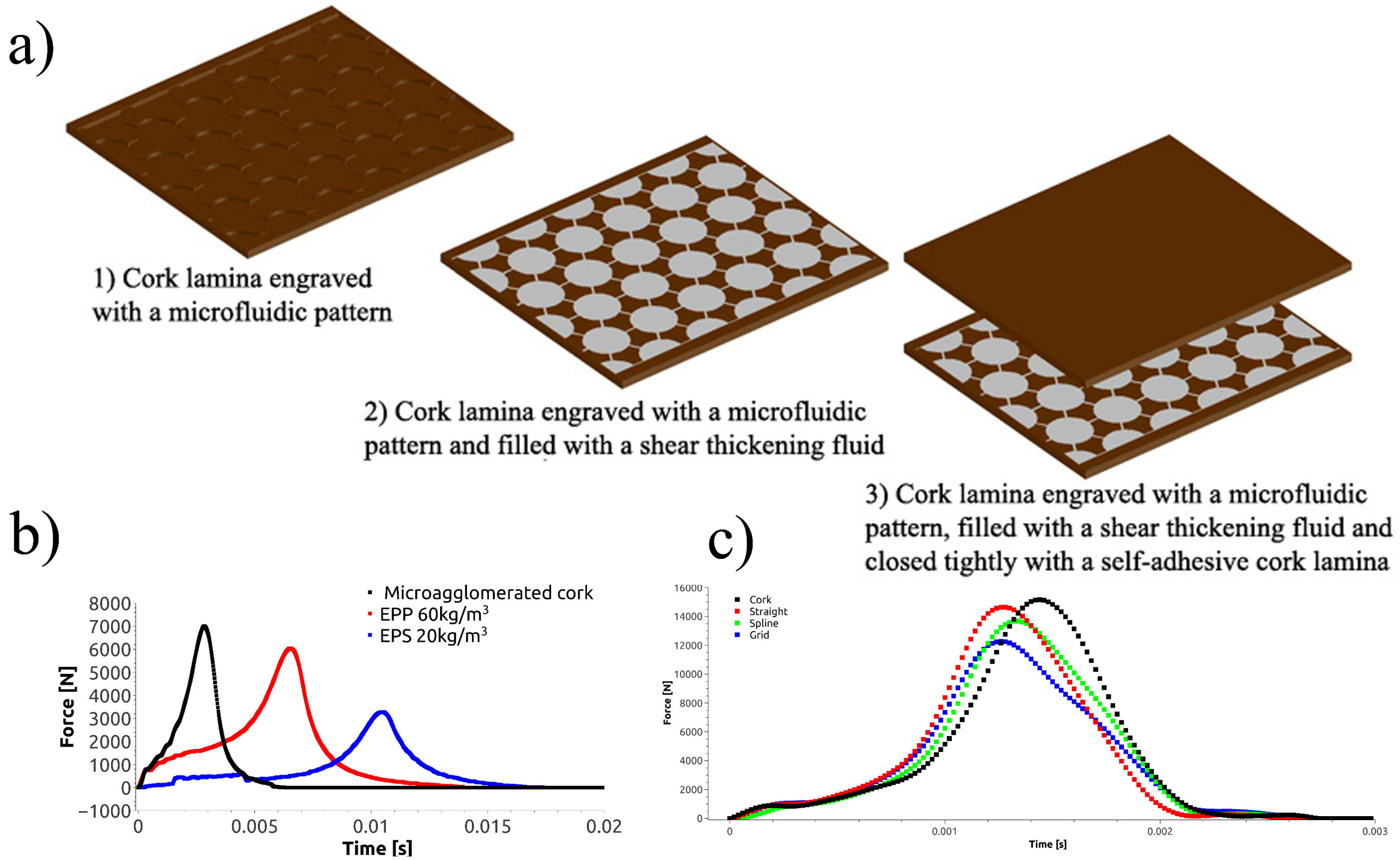
Figure 6.
Photographs of neat Kevlar fabric (a) and sphere silica/ethylene glycol (EG) suspension treated Kevlar composite fabric (b) after ballistic resistance testing. Reprinted with permission from [189], Copyright 2011, John Wiley and Sons.
Figure 6.
Photographs of neat Kevlar fabric (a) and sphere silica/ethylene glycol (EG) suspension treated Kevlar composite fabric (b) after ballistic resistance testing. Reprinted with permission from [189], Copyright 2011, John Wiley and Sons.
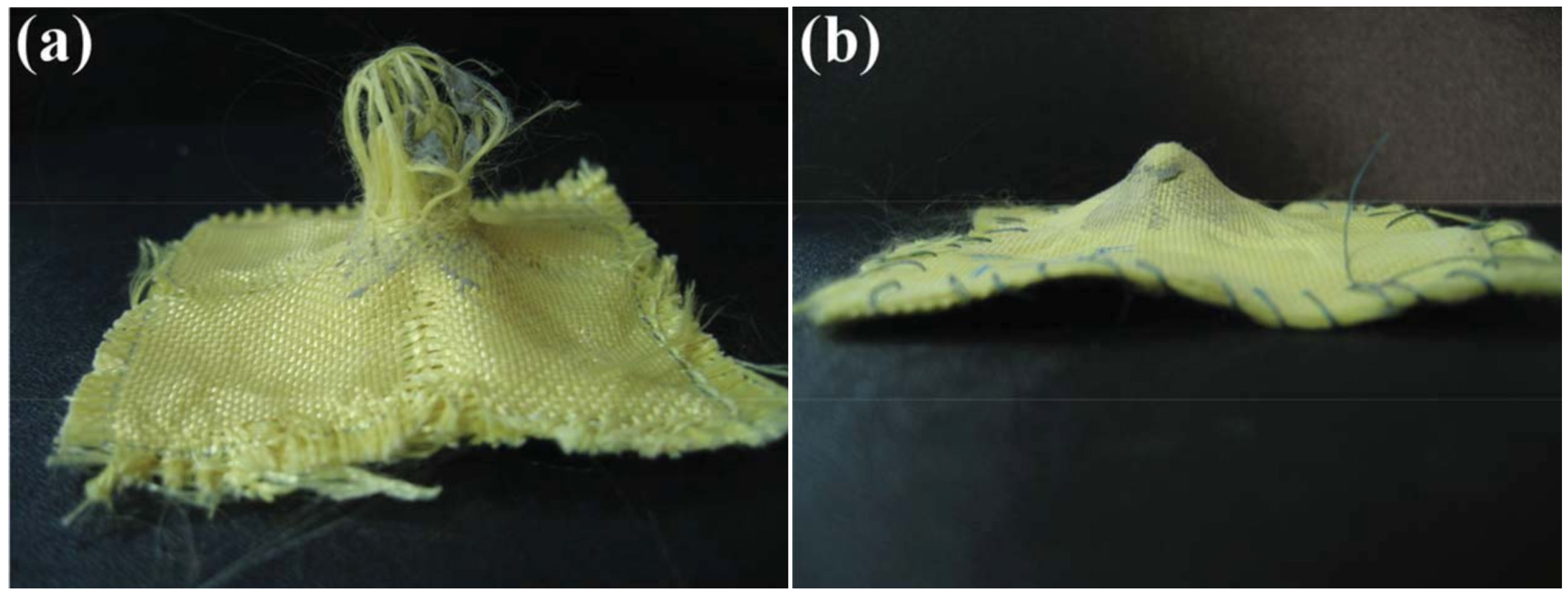

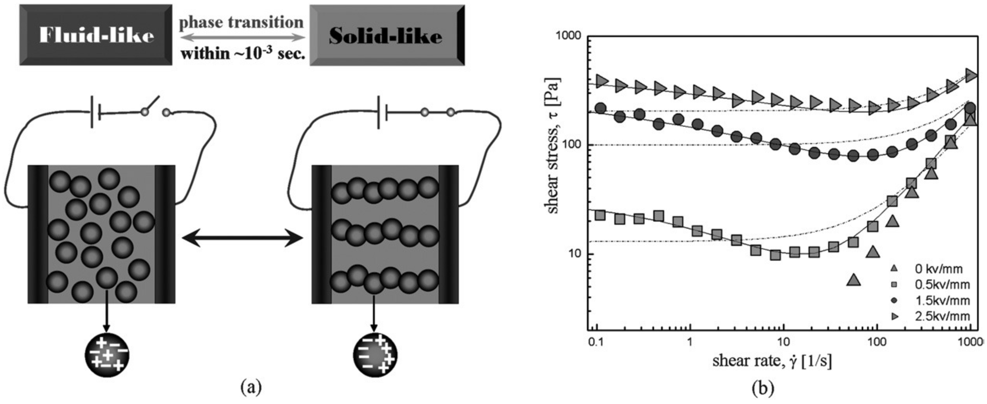
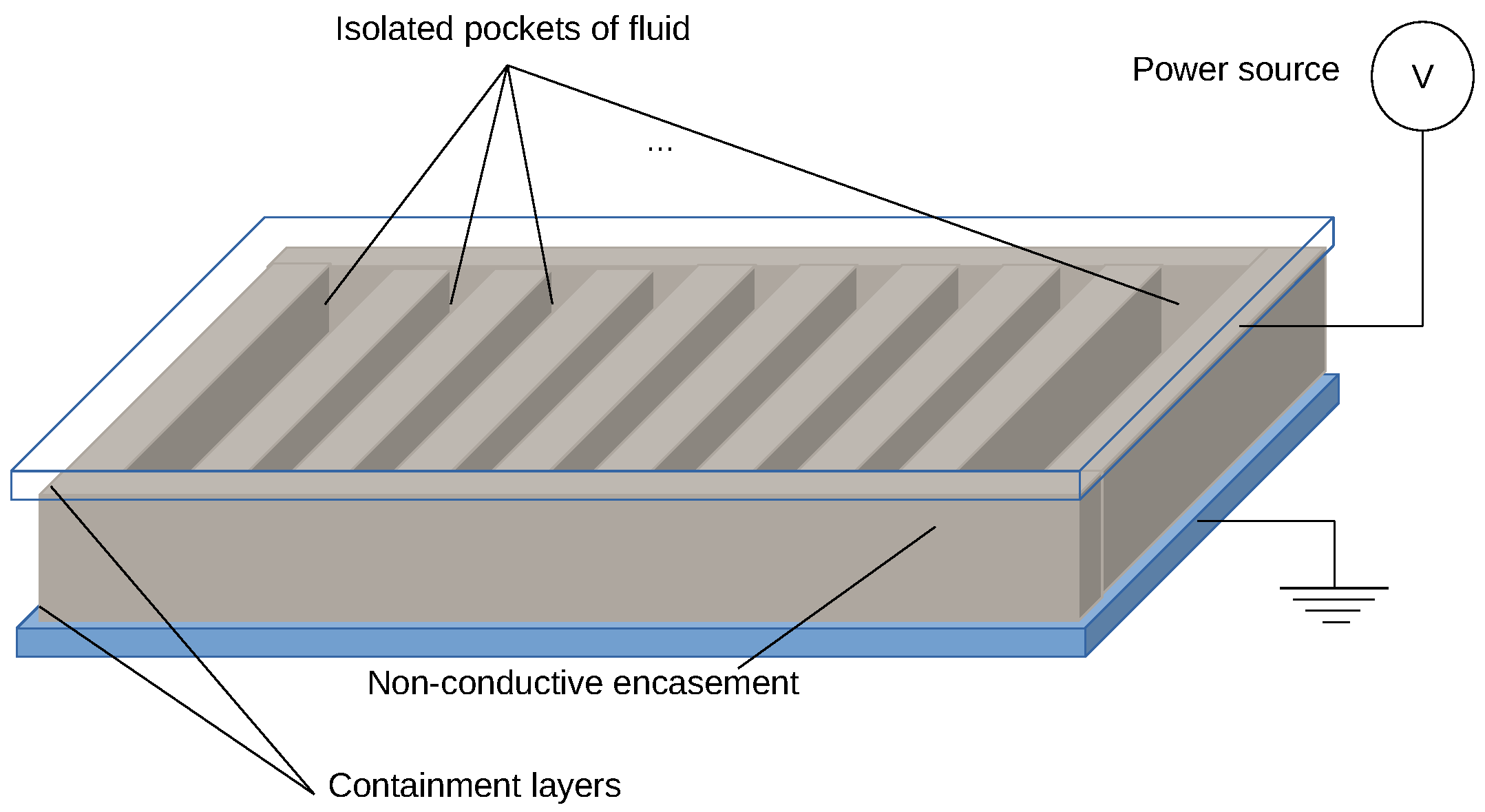
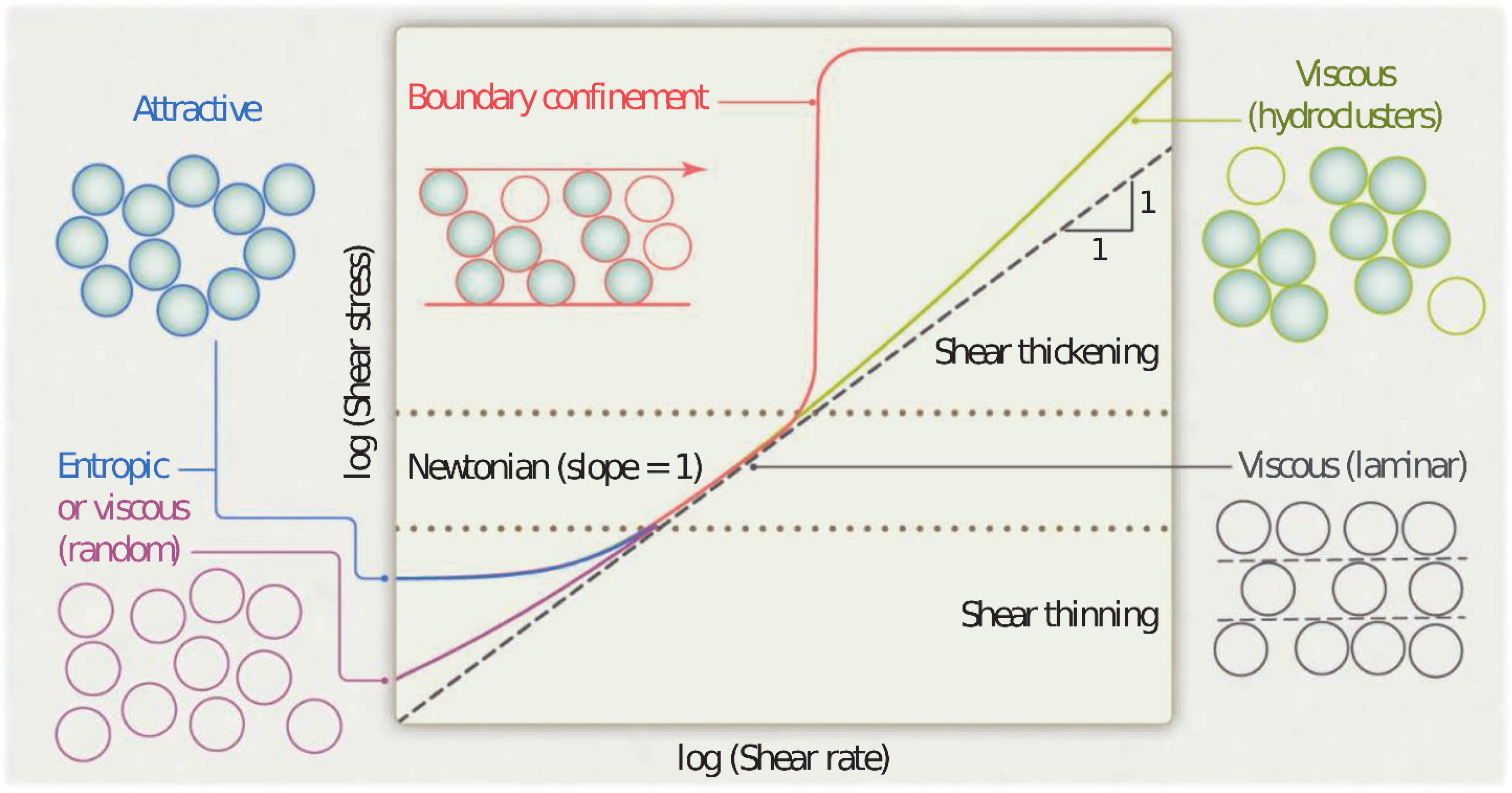
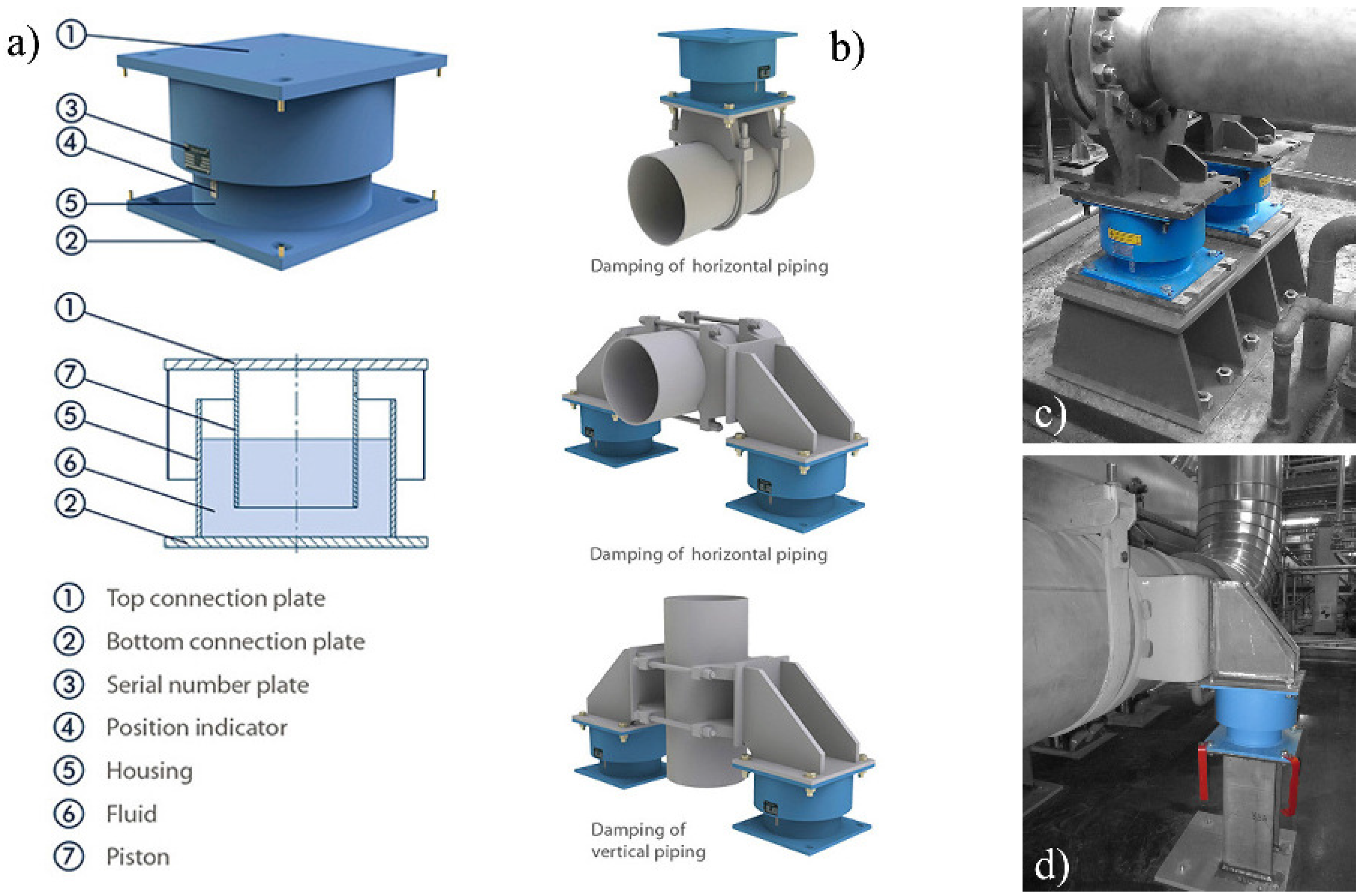
Table 1.
Summary of the most relevant applications of complex fluids in energy dissipating systems and their pros and cons.
| Application | Active-Fluids | Passive-Fluids | ||
|---|---|---|---|---|
| + | - | + | - | |
| Dampers | Versatility | Settling | Low cost | Unadaptability |
| Redispersibility | ||||
| Sandwich structures | Versatility | Settling | Low cost | Unadaptability |
| Heavy-weight | ||||
| Body armor | Versatility | Power dependence | Power independence | Unadaptability |
| Heavy-weight | Light-weight | |||
© 2016 by the author; licensee MDPI, Basel, Switzerland. This article is an open access article distributed under the terms and conditions of the Creative Commons Attribution (CC-BY) license (http://creativecommons.org/licenses/by/4.0/).
Share and Cite
MDPI and ACS Style
Galindo-Rosales, F.J. Complex Fluids in Energy Dissipating Systems. Appl. Sci. 2016, 6, 206. https://doi.org/10.3390/app6080206
AMA Style
Galindo-Rosales FJ. Complex Fluids in Energy Dissipating Systems. Applied Sciences. 2016; 6(8):206. https://doi.org/10.3390/app6080206
Chicago/Turabian StyleGalindo-Rosales, Francisco J. 2016. "Complex Fluids in Energy Dissipating Systems" Applied Sciences 6, no. 8: 206. https://doi.org/10.3390/app6080206
Note that from the first issue of 2016, this journal uses article numbers instead of page numbers. See further details here.