
State of the Art of Tactile Micro Coordinate Metrology


Federal Institute of Metrology METAS, 3003 Bern-Wabern, Switzerland
*
Author to whom correspondence should be addressed.
Appl. Sci. 2016, 6(5), 150; https://doi.org/10.3390/app6050150
Submission received: 21 March 2016
/
Revised: 27 April 2016
/
Accepted: 9 May 2016
/
Published: 16 May 2016
(This article belongs to the Special Issue Design and Applications of Coordinate Measuring Machines)
Abstract
:Micro parts are increasingly found in a number of industrial products. They often have complex geometrical features in the millimeter to micrometer range which are not accessible or difficult to measure by conventional coordinate measuring machines or by optical microscopy techniques. In the last years, several concepts of tactile micro coordinate measuring machines have been developed in research laboratories and were partly commercialized by industry. The major challenges were related to the development of innovative micro probes, to the requirements for traceability and to the performance assessment at reduced measurement uncertainty. This paper presents a review on state of the art developments of micro coordinate measuring machines and 3D micro probes in the last 20 years, as far as these were qualified in a comparable way, with a special emphasis on research conducted by the Federal Institute of Metrology METAS in this field. It outlines the accuracy limitations for the probe head including the probing element and for the geometrical errors of the machine axes. Finally, the achieved performances are summarized and the challenges for further research are addressed.

1. Introduction
Coordinate measuring machines (CMMs) have become versatile and widespread metrology tools to perform complex dimensional measurement tasks in an efficient way. There is an ongoing trend to miniaturization in mechanical and optical production technology, leading to industrial products with generally larger functionality in a smaller volume and with less energy consumption. Small components with often complex geometrical features are found, e.g., in medical products such as ear implants or hearing aids, in gears of micro motors, in small freeform lenses of mobile phones, in injection systems for the automotive industry, or in the telecom sector for fiber optic or next generation radio frequency technology components. Hence, there is a new demand for highly accurate dimensional measurements on micro parts having geometrical features in the meso scale, i.e., in the sub-millimeter to micrometer range. Such micro parts are often too complex and too large for optical microscopy techniques and their tiny structures are hardly accessible by means of conventional tactile coordinate measuring machines.
The major limiting factors of conventional CMMs for the measurement of small object features are the size of the probing element, the contact force as well as the CMM stage accuracy. Whereas modern multi-sensor CMMs with optical probes, mostly based on imaging systems, are well suited for the measurement of small features, only tactile probes have the fundamental properties needed for high precision full 3D capability with well established traceability. The paper discusses the key elements of tactile micro coordinate metrology, i.e., the probe head for probing objects with small styli and weak forces, the precision stages with an Abbe error free metrology system, as well as the system calibration and performance verification.
Several review papers have been published in the field of micro coordinate metrology, in particular on probing systems [1], on aspects of tactile probing [2] and more recently on existing performance verification infrastructure of micro CMMs [3]. The purpose of this paper is to present a review on state of the art machine and probe developments seeking ultimate accuracy for three-dimensional measurements of micro parts, with a special emphasis on those instruments, where comparable qualification and performance assessment results are available. The research conducted on the micro CMM at METAS [4] is presented in more detail, since this machine has been qualified extensively using methods relying as closely as possible on existing written standards.
2. Probe Developments
When measuring small features using a tactile probe, the influence of the probe-surface interaction gets more and more critical with decreasing size of the probing element. For smaller probe sphere radii, the contact area gets smaller and therefore effects of elastic or even plastic deformation of the surface due to static or dynamic measurement forces become very critical. The effects of surface deformation by over-travel forces due to the probe stiffness and of impact forces due to the probe mass, dynamic excitations due to vibrations, surface forces as well as tip rotations due to stylus bending or rotation has been extensively studied by Bos [2]. Conventional probe systems of CMMs did not fulfil the stringent requirements regarding low stiffness and low dynamic mass nor the accuracy requirements set by ultra precision CMMs, therefore new systems had to be developed. A review over a wide range of probing systems has been given by Weckenmann et al. [1].
One the first micro probes has been developed jointly by PTB and Werth in 1998 [5] and soon after implemented on commercial multi-sensor CMMs. It is based on a glass fiber with a quasi spherical melted end whose position is measured with an opto-electronic system. Tip diameters down to 20 µm can be realized. Whereas the first probes had only 2D capability, Werth has developed in the mean time a fiber probe with full 3D capability [6]. The probe is available on Werth multi-sensor CMMs and has proven its usefulness in many applications, in particular for the measurement of small holes. Probing errors of a few hundred nanometers are specified, limited mainly by the relatively large form deviations of the melted glass sphere tips.
PTB developed a probe based on a micro-fabricated silicon membrane with piezo-resistive sensors [7], first published in 1999. The system measures two angular and one translational movement of the probing element. The stiffness in horizontal direction depends on the shaft length and is usually not the same as in the vertical direction. The probe design has been commercialized in the meantime and is available on the F25 micro CMM from Zeiss. The manufacturer specifies a probing error of 250 nm [8].
Approximately at the same time, NPL has also developed a micro-fabricated probe based on three angled flexible elements with capacitive sensors [9]. This original design has been commercialized as the Triskelion probe by IBS [10]. The manufacturer indicates the 3D measurement uncertainty of tip deflection to be below 20 nm. More recently NPL developed a novel vibrating micro-probe, based on the Triskelion design with six piezoelectric sensors and actuators, two on each flexure [11]. The design is optimized to feature high isotropy and very low contact forces in the µN range, thus reducing effects of surface interaction forces [2]. Experimental results to qualify the probe are not yet published.
A similar probe design using three angled flexible elements, but based on a monolithic silicon chip with piezo-resistive sensors and suitable for mass production, has been developed by TUE [12] and first published in 2001. Meanwhile, this is commercialized as the Gannen probe by XPRESS [2,13]. It is specified with a combined 3D probe uncertainty of 45 nm.
Another micro probe which is commercially available was developed by the CMM manufacturer Mitutoyo. The UMAP probe, implemented on the UMAP vision system since 2002 [14], is based on an ultrasonic micro-vibration sensor and available with stylus tip diameters between 15 µm and 300 µm. The accuracy of the probe itself is not specified.
In order to overcome the trade-off between the stiffness requirements of the probing system at contact and during approach, the University of Nottingham is actually developing a probing system for micro CMMs with variable stiffness [15]. While still under development, first promising experiments resulted in an expanded uncertainty of the probing system of about 60 nm. Issues of drift and stylus tip displacement while switching the stiffness yet need to be addressed.
Further probe developments still in the research phase are conducted in Asia: The Hefei University of Technology has been working on several concepts, all based on glass or tungsten styli attached to a floating plate, the latter being suspended on wires or leaf springs [16,17,18]. The deflection is measured with laser focus sensors or with a laser interferometer combined with an autocollimator based optical sensor for the angular motion. Their latest development includes fiber Bragg grating sensors to measure the deflection of the three arc-shaped cantilevers holding the stylus [19]. The University of Kitakyushu is working on a vibrating fiber probing system [20]. It consists of an extremely fine optical fiber with a glass tip diameter of 5 µm, but it is limited to probing in x/y-direction only.
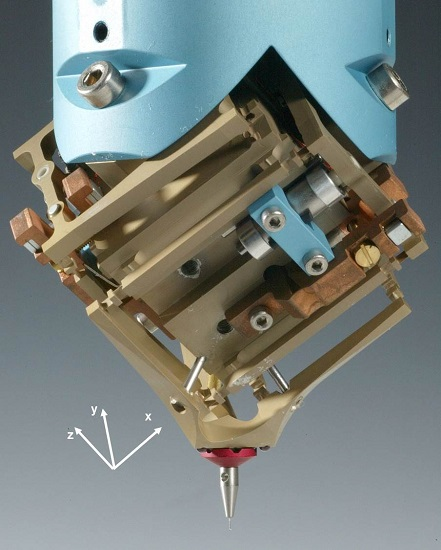
METAS has developed, in collaboration with the Swiss Federal Institute of Technology EPFL and the industrial partner Mecartex, a 3D probe manufactured out of a single piece of aluminum by conventional milling and electro-discharge machining [4,21]. Its filigree parallel kinematic structure (Figure 1) with 60 μm thick flexure hinges minimizes the moving mass and leaves the probing sphere exactly three translational degrees of freedom. It has a stiffness of 20 N/m and exhibits perfectly isotropic probing forces below 0.5 mN at 20 µm deflection. The probe head allows for exchangeable styli with probe sphere diameters ranging from 0.1 mm to 1 mm. The probe deflection, i.e., the x/y/z components of the translational motion, is measured by three inductive sensors. The tilted orientation of the probe head coordinate system (Figure 1) greatly facilitates the access to the probe head for exchangeable styli and also implicates, that all three axes are affected by the gravitational force in an identical way, allowing for isotropic probing forces even when changing the stylus weight.
3. Stage and Metrology Systems Design
The second critical element of an accurate micro CMM is the 3D translation stage with the metrology system. In order to achieve smallest uncertainties, the Abbe principle must be strictly fulfilled, i.e., the reference scale must be in line with the measured length and thus always pointing towards the probe element for all positions of the stage, which imposes severe design restrictions. For classical CMMs with large measurement volumes, this cannot be realized due to limited space and disproportional cost.
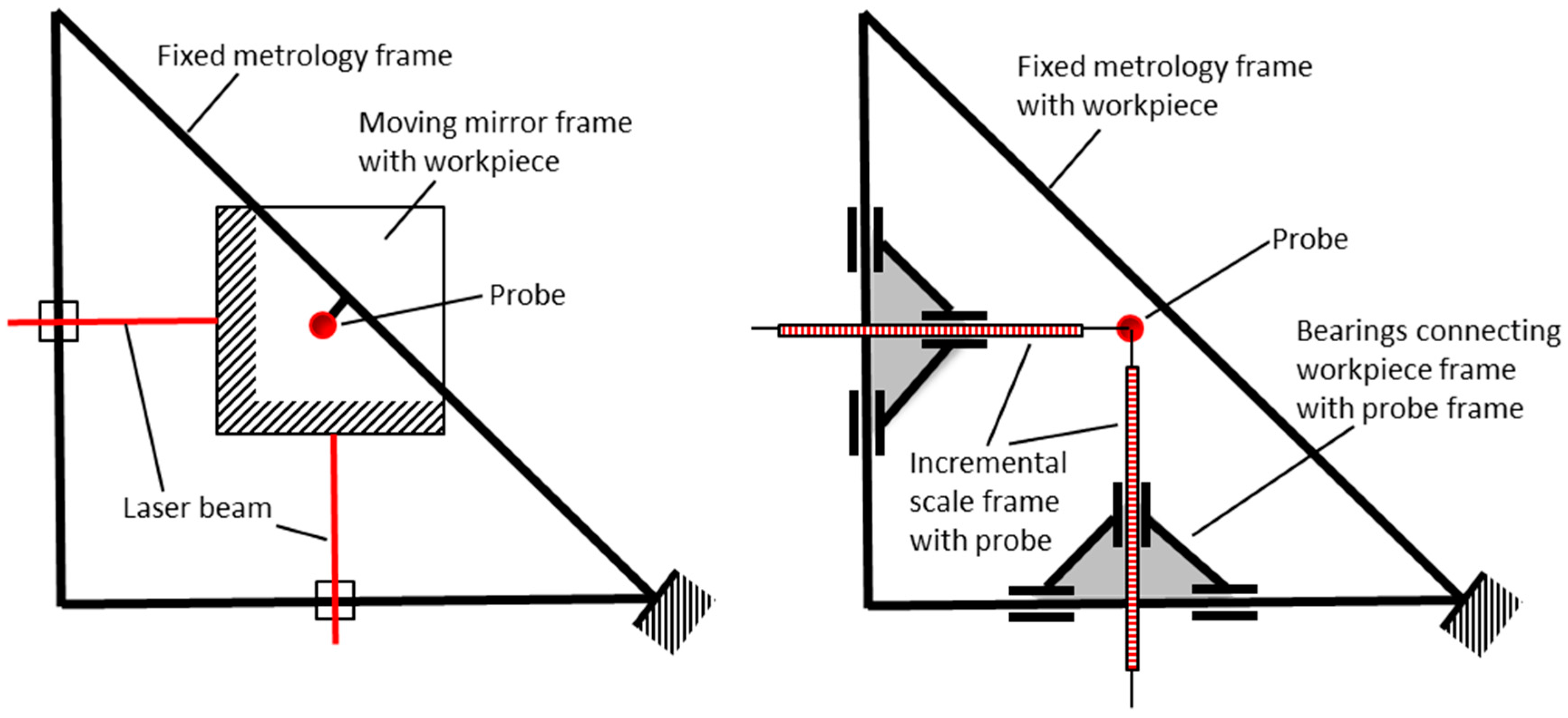
Two major classes of metrology systems can be distinguished, i.e., laser interferometer and incremental scale based systems. Abbe free stages with interferometers use a moving frame with mirrors onto which usually the workpiece is placed, as it is shown for the two-dimensional case in Figure 2 (left). Plane mirror interferometers are used to measure the displacement of the mirror frame with respect to the metrology frame with the probe. To build an Abbe free measurement stage using incremental scales is somewhat more complicated because the scales need to be connected with both frames and therefore require additional bearings. Figure 2 (right) shows a possible solution in 2D, as proposed by Vermeulen et al. [22]. Whereas measurement stages with incremental scales are more robust for industrial environment and potentially cheaper, they have the disadvantage, that the additional bearing between the two frames is part of the measurement loop and thus induces an additional uncertainty contribution.
Incremental scale based measurement stages have been proposed by TUE [22], which was later on commercialized by Zeiss for the micro coordinate machine F25 [8] (the instrument F25 is no longer part of the product portfolio of Zeiss). In this design, the Abbe principle is respected for the x/y-stage, while for a z-displacement of the probe out of the x/y-plane an Abbe offset must be taken into account. The F25 provides a measurement volume of 100 mm × 100 mm × 100 mm. A similar design, but with all three axes in Abbe, has been realized by TUE [23] for the TriNano micro CMM and is commercialized by XPRESS [13].
One of the first Abbe free interferometric stages for coordinate metrology was realized at NPL: a conventional CMM was used for the 3D movement of a cube corner supporting the mirrors for reflecting the interferometer beams [9]. TU Illmenau designed an ultra-precise 3D stage with Zerodur® (Schott AG, Jena, Germany) frame and a multi-axis interferometer including angular motion (yaw) measurement for their nano-positioning and nano-measuring machine NMM [24], which is commercialized by SIOS [25]. The Hefei University of Technology built two prototype micro CMMs, both with roller bearing stages driven by piezo motors and laser interferometers for stage position sensing [26,27].
An original ultra precision stage development at Philips CFT [28] has been installed at METAS and was the basis for a new development by IBS [29] leading to the Isara 400 machine [30]. The ultraprecision stage of the METAS micro CMM [4,28] has vacuum preloaded air bearings. The stages are driven by Lorenz actuators and their motion is measured and controlled by three plane mirror heterodyne interferometers. The original V-configuration of the guideways with wedges as shown in Figure 3 makes the stage very compact and stiff. The working volume of the stage is 90 mm × 90 mm × 38 mm. According to Figure 2 (left) the probe head remains in a fixed position connected to the metrology frame while the stage is moving the workpiece during measurements. The workpiece is located in a Zerodur cube corner with three perpendicular flat mirrors forming the reference coordinate system. All three interferometer beams measuring the workpiece displacement are pointing to the center of the probing sphere, thus limiting the residual Abbe offset to the probe radius.
4. System Calibration and Performance Verification
4.1. Probe Calibration
4.1.1. Single Point Probing
The single point probing behavior of a CMM probe can be characterized by the PFTU value (single stylus form error) as specified in the standard ISO 10360-5 [31], based on the peak-to-valley deviation of 25 probing points on a sphere arranged according to Figure 4 (left). For two of the micro CMMs presented above, corresponding results are available. The PFTU value for the Zeiss F25 probe was found from the average of 14 measurements to be 189 nm with 60 nm standard deviation and all values but one complying with the manufacturer specification of 250 nm [8]. A repeatable pattern was found in these measurements, most probably due to the anisotropic behavior of the silicon chip membrane as suggested by Bergmans et al. [8].
METAS has carried out the same standardized test [31] for single point probing error on a 1 mm diameter sphere [32]. The test was performed four times with the sphere rotated by 90° between each test. The sphere radius was found to be between 0.500202 nm and 0.500211 nm with a standard deviation of 4 nm. The test resulted in PFTU values between 53 nm and 67 nm with an average value of 58 nm. The measurements in Figure 4 (right) show a systematic behavior probably due to an uncompensated form deviation of the probing sphere. The Si3N4 test sphere [33] had an estimated form deviation of less than 15 nm.
4.1.2. Scanning
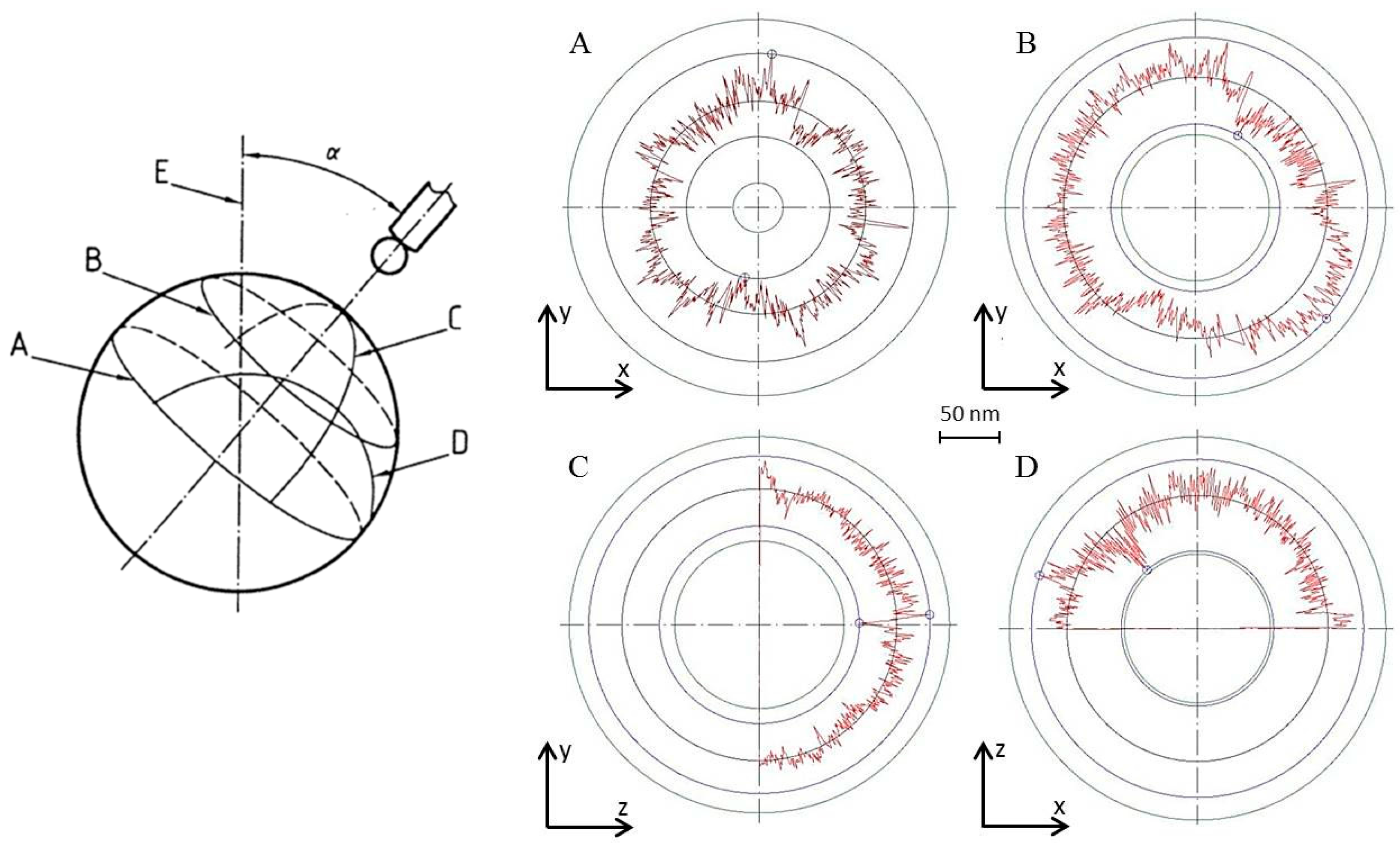
The standard ISO 10360-4 [34] describes the scanning probing error Tij which is the range of radial distances obtained from four circular scans on a sphere: one full circle in an equatorial plane, a second full circle in a plane parallel to the first, a third half circle through the pole, and a fourth half circle in a plane perpendicular to the third at a distance of about 1/2 of the radius from the pole (Figure 5, left).
This test was performed with the METAS probe on a 1 mm ruby sphere with a point density of 300 pts/mm [35]. The LS diameter fitted through the scan profiles resulted in 1.000806 mm, compared to the value of 1.000804 mm found by the independent probe sphere diameter determination as shown in Section 4.1.3. For Tij a value of 87 nm was obtained. The corresponding values for the four individual scans were 51 nm, 75 nm, 67 nm and 78 nm, respectively. It must be noted that these values comprise the form deviation of the reference sphere (53 nm), the uncompensated form deviation of the probing sphere and surface roughness contributions of both spheres, as no filtering was applied.
4.1.3. Probe Sphere Diameter and Form Correction
On a conventional CMM the absolute diameter of the probe sphere is calibrated on a reference sphere. At the same time the anisotropic behavior of the probe head including stylus bending is corrected. This requires an independent calibration of the diameter of the reference sphere and assumes the roundness deviation of both, the reference sphere and the probe sphere, to be much smaller than the overall probing error, which is generally the case. For high precision micro coordinate metrology, the requirements for the reference sphere are much higher and cannot be fulfilled by independent calibrations. Therefore, an error separation method was developed involving three nominally identical spheres compared against each other in various configurations, using one of the spheres both as the probe sphere and the reference sphere, respectively [36]. In this way, both the absolute diameter and the sphericity deviation of three 1 mm ruby spheres could be mapped over their entire accessible surface. This method finally relies directly on the traceability of the CMM stage interferometer and on the repeatability of the probe being usually below 4 nm (standard deviation). Figure 6 shows a sphericity map of one of the measured spheres with a form deviation of 33 nm.
4.2. Stage Calibration and Error Correction
The way of calibrating the measurement stage depends much on its design (Section 3). Measurement stages for micro CMMs with incremental scales are calibrated and corrected similarly to conventional machines, i.e., the position accuracy is measured with a laser interferometer and the geometrical errors are usually determined with the help of artefacts. For the F25 machine some measurement results were published by PTB [37]. They carried out straightness measurements on a Zerodur gauge block assembly along the horizontal y-axis over 43 mm, resulting in a straightness deviation of about 30 nm with a reproducibility that would allow for a further correction down to a few nanometers residual error. A similar measurement along the vertical z-axis over a length of 1.75 mm (limited by the length of the stylus shaft) resulted in a straightness deviation of less than 10 nm.
The calibration of interferometer based stages includes the calibration of the laser wavelength (given by the optical frequency and the refractive index determined by the compensation unit), and—more critically—the flatness and squareness of the faces of the reference mirror cube. For the flatness calibration of the reference mirrors, high precision reference artefacts are used. IBS reported on flatness measurements using a Zerodur block with a metallic coating allowing for a capacitive sensor to be used instead of the tactile probe [29] und thus improving resolution and noise due to surface roughness and probe repeatability. The squareness calibration was made using the same artefact by applying a reversal technique.
The calibration and correction of the Zerodur reference mirror of the METAS micro CMM has been made in a similar way as described above [35]. For this, a Zerodur block of 100 mm × 60 mm × 40 mm with form deviations <10 nm was used. The gold coated block was scanned by a capacitance sensor. Where possible, reversal techniques were applied to separate the errors. The resulting errors were then mapped in correction files. The calibration of the squareness in x/y-plane was made with the help of a ball plate. The squareness of the z-axis with respect to horizontal axes was calibrated with the help of a Ø 44 mm tungsten carbide sphere, by scanning the sphere in two half-circles in the x/z- and the y/z-planes and adjusting the corresponding orthogonality angles as to obtain minimum residuals from a circle. Although somewhat less sensitive than checking the orthogonality by, e.g., measuring a ball bar in diagonal directions, the method using a sphere is more efficient and provides an independent performance check.
4.3. Performance Tests
Performance tests of micro CMMs can be made in the same way as for conventional machines following the procedure of the acceptance and reverification test ISO 10360-2 [38] using specially designed small artefacts. Since the target uncertainties are in the nanometer range, the stability of these artefacts is a particular challenge. The quantity to be determined in the above cited ISO test is E0, the error of indication of a calibrated test length.
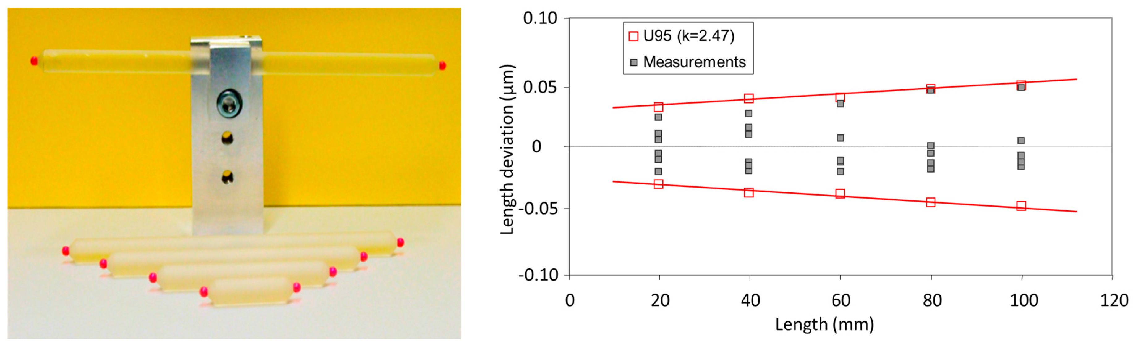
Ball bars of different lengths ranging from 20 mm to 100 mm were manufactured using Zerodur bars and ruby spheres (Figure 7). The results shown in Figure 7 assess the E0 value of the machine in the whole volume to be 27 nm + 0.2 × 10⁻⁶ × L [35]. Since the test requires the ball bar to be measured along the diagonals of the volume, one can compute the squareness between the three machine axes. It is an accurate method since the longest diagonal length can be measured.
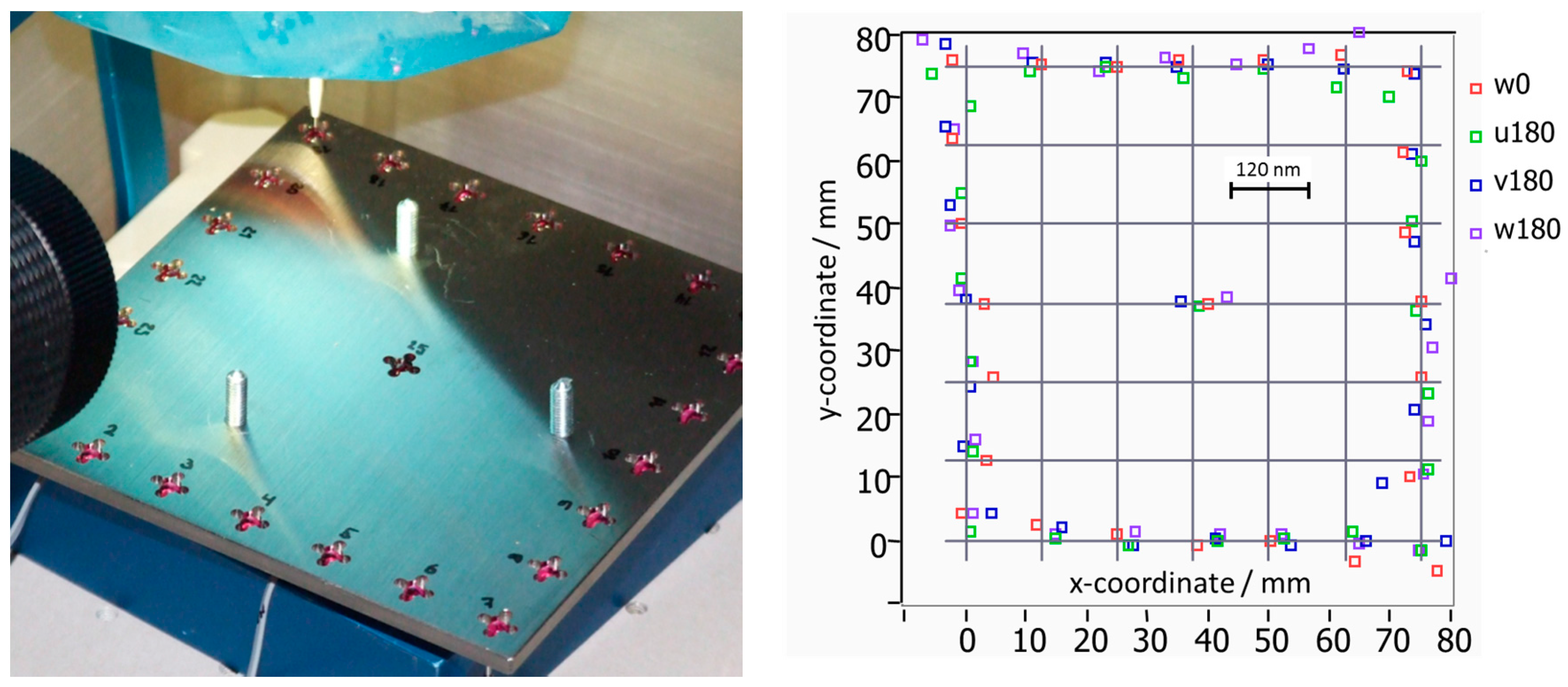
Ball plates are another suitable artefact to test the performance of a CMM. The calibration method requires measurements in 4 positions (two from each side of the plate) in order to be able to separate the errors of the CMM from the deviations of the ball plate nominal positions. The ball plate used in the test hereafter was manufactured using 25 ruby spheres, Ø 3 mm, pressed into the holes of an 85 mm × 85 mm invar frame (Figure 8).
Apart from the squareness error between the axes, as it is also obtained from ball bar measurements described above, the method also provides information about other error contributions, such as axes straightness or angular distortions. As shown in Figure 8 the measurement results on the METAS micro CMM exhibit a residual squareness error of (0.17 ± 0.05)". The contributions from other error sources, which are smaller than 40 nm, are largely dominated by temperature drifts. Evaluating the 300 relative distances between all measured ball center positions in a similar way as in Figure 7 (right) leads to a 95% confidence length measurement error of E0 = 26 nm + 0.23 × 10⁻⁶ × L, a value very close to the one obtained using the ball bars.
PTB and METAS carried out a bilateral comparison on a 90 mm × 90 mm Zerodur plate with hemispheres [39]. The average difference of the hemisphere x- and y-coordinates was 12 nm and 7 nm respectively, with a maximum value of 28 nm. It must be noted that, since an error separation calibration procedure was applied, these measurements do not represent the deviations of the machine, but only the capability and comparability of calibrating a ball plate standard.
5. Challenges for Further Development
To extend the use of tactile micro coordinate metrology for a large variety of industrial applications, a series of challenges need to be addressed.
5.1. Accessibility of 3D Features
Quite often, the geometrical features of a micro-parts are not easily accessible with a spherical probe on a straight stylus, but limited by the probe diameter for small holes, by the stylus length for high aspect features such as deep holes, or by the direction of the probe stylus. Therefore, smaller probe elements with smaller and better known form deviation, longer styli to access deep holes and smaller probing forces to allow for longer styli need to be developed. To achieve a better accessibility of normally hidden features, probes with multiple, i.e., star-shaped styli were built [40], their application turned out to be delicate for standard use, however. Another approach is to implement additional rotational axes on the micro CMM [41], obviously at the cost of accuracy due to uncorrected guide and positional errors of the rotation axes.
5.2. Probe/Surface Interaction
The smaller the workpiece features, the probe sphere diameter and the targeted measurement uncertainty are, the more important becomes the interaction of the probe with the surface. Not only effects of surface indentation due to measurement forces [2], but also stylus wear and deposition of wear debris on the probe sphere become relevant [42]. These effects can be significantly reduced by selection of appropriate materials for the probe sphere, e.g., diamond coated spheres [43].
5.3. Task Specific Uncertainty
Performance verification tests as described in Section 4 may result in standardized length measurement errors and qualify the probe errors, but do provide only some basic contributions to the uncertainty of a specific geometrical feature to be determined. Length measurement errors are certainly not adequate for the uncertainty of derived geometrical elements, such as a local radius, a form deviation or an angle. Methods for the estimation of reliable, task specific measurement uncertainties still need to be developed further and are not yet mature for day to day applications. A promising approach is the Virtual CMM based on numerical simulation [44,45], which has been successfully implemented on the METAS micro CMM [46], but which still requires a considerable effort in modelling and computing. Further research is needed for refining and implementing the error model adapted to the particular characteristics of a micro CMM and integrating this directly into a high level software, allowing to achieve estimations of uncertainty not only off-line, but with much higher computing speed almost in real-time during the measurement process.
5.4. Application in Industry
For a wider use of tactile micro coordinate metrology in industry, several issues need to be further addressed. The need for fast and efficient measurements contradicts to the requirements of slow approaching speed to achieve small contact forces and thus asks for improvements of the dynamic properties of machines and probes. Another problem is the fragility of probing systems and styli, which easily break due to overtravel or uncontrolled manipulation. Systems with the possibility of exchangeable styli obviously help to save costs of replacing the entire probe system. Finally, industry is asking for comparability of measurement results and of system specifications. A written standard for performance verification dedicated to micro CMMs, or preferably an amendment of an existing standard is clearly needed [3].
6. State of the Art and Conclusions
As outlined earlier there are actually a few types of machines for high precision tactile micro coordinate measurements available, which have full 3D measurement capability and are operational with a high-level software platform to provide industrial measurement services: the well established Zeiss F25 [8], from which about 25 machines were sold and are operating in research labs and institutes worldwide, but is unfortunately no longer commercially available; two more recent developments, the Isara 400 [30] and the TriNano [13,23] are both in principle commercially available, but the market uptake did not really happen so far; the micro CMM at METAS [4] is a prototype development, which is fully operational since 2006 and almost daily used for providing calibration and measurement services to industry. Also to be mentioned is the commercially available SIOS nanopositioning and nanomeasuring machine [24,25], which can be configured with a suitable probe to perform 3D coordinate measurements. Furthermore, micro CMMs were developed by Hefei University of Technology [26,27], complemented by tactile micro probe developments [16,17,18,19] to achieve 3D measurement capability. These latter laboratory instruments, however, are still in the development phase and have not proven yet their full measurement capability following standardized procedures as outlined in Section 4. Not discussed further in this context are multi-sensor CMMs, such as [6,14], which have accuracies closer to conventional CMMs.
State of the art probes of above mentioned instruments do achieve a repeatability of a few nanometers, but the best values reported for the 3D probing error according to standardized specification tests [31,34] are around 50 nm, with similar performance for single point probing and scanning. The achievable probing errors are limited mainly by the form deviation and the roughness of the probing sphere, and the overall stability of the instrument during the test procedure. State of the art CMM stages were demonstrated to have maximum errors of indicated length according to a standardized specification test [38] in the entire volume and in arbitrary direction of about 60 nm, limited by the uncorrected flatness deviation of the reference mirrors, residual squareness errors and the errors of the probe, the latter being part of the mentioned specification test.
In conclusion, in spite of the big research and development effort spent worldwide for tactile micro coordinate metrology, there are still very few results available for a comparable performance verification according to standardized procedures. The reason for this is partly that many instruments and probe systems are still in the development phase, but there is also a lack of generally accepted and widely available material standards and written standards dedicated to the particular characteristics of micro CMMs.
Acknowledgments
This work was funded by the R & D-Program at METAS and the European Metrology Research Program EMRP.
Author Contributions
M.F., A.K. and R.T. conceived and designed the experiments; A.K. performed the experiments and analyzed the data; R.T. wrote the paper.
Conflicts of Interest
The authors declare no conflict of interest.
Abbreviations
The following abbreviations are used in this manuscript:
| CMM | Coordinate measuring machine |
| 3D | Three dimensional |
References
- Weckenmann, A.; Estler, T.; Peggs, G.; McMurtry, D. Probing systems in dimensional metrology. Ann. CIRP 2004, 53, 657–684. [Google Scholar] [CrossRef]
- Bos, E.J.C. Aspects of tactile probing on the micro scale. Precis. Eng. 2011, 35, 228–240. [Google Scholar] [CrossRef]
- Claverley, J.D.; Leach, R.K. A review of the existing performance verification infrastructure for micro-CMMs. Precis. Eng. 2014, 39, 1–15. [Google Scholar] [CrossRef]
- Küng, A.; Meli, F.; Thalmann, R. Ultraprecision micro-CMM using a low force 3D touch probe. Meas. Sci. Technol. 2007, 18, 319–327. [Google Scholar] [CrossRef]
- Guilun, J.; Schwenke, H.; Trapet, E. Opto-tactile sensor for measuring small structures on coordinate measuring machines. Proc. ASPE 1998, 18, 25–28. [Google Scholar]
- Werth 3D Fibre Probe. Available online: http://www.werth.de/index.php?id=262&L=1 (accessed on 26 April 2016).
- Buetefisch, S.; Dai, G.; Danzebrink, H.-U.; Koenders, L.; Solzbacher, F.; Orthner, M.P. Novel design for an ultra high precision 3D micro probe for CMM applications. Procedia Eng. 2010, 5, 705–712. [Google Scholar] [CrossRef]
- Bergmans, R.H.; Nieuwenkamp, H.J.; van Veghel, M.G.A. Probing behavior of a microCMM. In Proceedings of the 11th Euspen International Conference, Como, Italy, 23–26 May 2011; Volume 1, pp. 104–107.
- Peggs, G.N.; Lewis, A.; Oldfield, S. Design of a compact high-accuracy CMM. Ann. CIRP 1999, 48, 417–420. [Google Scholar] [CrossRef]
- IBS Precision Engineering. Available online: http://www.ibspe.com/category/isara-400-3d-cmm/triskelion-touch-probe.htm (accessed on 26 April 2016).
- Claverley, J.K.; Leach, R.K. Development of a three-dimensional vibrating tactile probe for miniature CCMs. Precis. Eng. 2013, 37, 491–499. [Google Scholar] [CrossRef]
- Haitjema, H.; Pril, W.O.; Schellekens, P.H.J. Development of a silicon-based nanoprobe system for 3-D measurements. Ann. CIRP 2001, 50, 365–368. [Google Scholar] [CrossRef]
- XPRESS Precision Engineering B.V. Available online: http://www.xpresspe.com/probe2.php (accessed on 26 April 2016).
- Mitutoyo. Available online: http://www.mitutoyo.co.jp/eng/new/news/2002/02_13.html (accessed on 26 April 2016).
- Alblalaihid, K.; Kinnell, P.; Lawes, S.; Desgaches, D.; Leach, R. Performance Assessment of a New Variable Stiffness Probing System for Micro-CMMs. Sensors 2016, 16, 492. [Google Scholar] [CrossRef] [PubMed] [Green Version]
- Fan, K.C.; Cheng, F.; Wang, W.; Chen, Y.; Lin, J.Y. A scanning contact probe for a micro-coordinate measuring machine (CMM). Meas. Sci. Technol. 2010, 21, 054002. [Google Scholar] [CrossRef]
- Li, R.J.; Fan, K.C.; Miao, J.W.; Huang, Q.X.; Tao, S.; Gong, E.R. An analogue contact probe using a compact 3D optical sensor for micro/nano coordinate measuring machines. Meas. Sci. Technol. 2014, 25, 094008. [Google Scholar] [CrossRef]
- Li, R.J.; Fan, K.C.; Huang, Q.X.; Zhou, H.; Gong, E.R.; Xiang, M. A long-stroke 3D contact scanning probe for micro/nano coordinate measuring machine. Precis. Eng. 2016, 43, 220–229. [Google Scholar] [CrossRef]
- Liu, F.F.; Chen, L.J.; Wang, J.F.; Xia, H.J.; Li, R.J.; Yu, L.D.; Fei, Y. Modeling and prototyping of a fiber Bragg grating-based dynamic micro-coordinate measuring machine probe. Meas. Sci. Technol. 2016, 27, 025016. [Google Scholar] [CrossRef]
- Murakami, H.; Katsuki, A.; Sajima, T.; Suematsu, T. Study of a vibrating fiber probing system for 3-D micro-structures: Performance improvement. Meas. Sci. Technol. 2014, 25, 094010. [Google Scholar] [CrossRef]
- Meli, F.; Fracheboud, M.; Bottinelli, S.; Bieri, M.; Thalmann, R.; Breguet, J.-M.; Clavel, R. High precision, low force 3D touch probe for measurements on small objects. In Proceedings of the Euspen International Topical Conference, Aachen, Germany, May 2003; pp. 411–414.
- Vermeulen, M.M.P.A.; Rosielle, P.C.J.N.; Schellekens, P.H.J. Design of a high-precision 3D-coordinate measuring machine. Ann. CIRP 1998, 47, 447–450. [Google Scholar] [CrossRef]
- Van Riel, M.; Moers, T. Nanometer uncertainty for a micro price. Mikroniek 2010, 50, 13–17. [Google Scholar]
- Jäger, G.; Manske, E.; Hausotte, T.; Buchner, H.-J. The metrological basis and operation of nanopositioning and nanomeasuring machine. Tech. Mess. 2009, 76, 227–234. [Google Scholar] [CrossRef]
- SIOS Meßtechnik GmbH. Available online: http://www.sios-de.com/?page_id=635 (accessed on 26 April 2016).
- Fan, K.C.; Fei, J.T.; Yu, X.F.; Chen, Y.J.; Wang, W.L.; Chen, F.; Liu, S.L. Development of a low-cost micro-CMM for 3D micro/nano measurements. Meas. Sci. Technol. 2006, 17, 524–532. [Google Scholar] [CrossRef]
- Huang, Q.X.; Wu, K.; Wang, C.; Li, R.J.; Fan, K.C.; Fei, J.T. Development of an Abbe Error Free Micro Coordinate Measuring Machine. Appl. Sci. 2016, 6, 97. [Google Scholar] [CrossRef]
- Ruijl, T. Ultra Precision Coordinate Measuring Machine; Design, Calibration and Error Compensation. Ph.D. Thesis, Technical University of Delft, Delft, The Netherlands, February 2001. [Google Scholar]
- Widdershoven, I.; Spaan, H.A.M. Calibration of the ISARA 400 ultra-precision CMM. In Proceedings of the First International Workshop on Advances in IT—Service Process Engineering, Guadeloupe, France, 23–28 February 2011.
- IBS Precision Engineering. Available online: http://www.ibspe.com/category/isara-400-3d-cmm.htm (accessed on 26 April 2016).
- ISO 10360-5. Geometrical Product Specifications (GPS)—Acceptance and Reverification Tests for Coordinate Measuring Machines (CMM)—Part 5: CMMs Using Single and Multiple Stylus Contacting Probing Systems; International Organization for Standardization: Geneva, Switzerland, 2010. [Google Scholar]
- Küng, A. Towards Truly 3D Metrology for Advanced Micro-Parts. EURAMET Project 1088. 2012. Available online: http://www.euramet.org/technical-committees/length/tc-l-projects/ (accessed on 26 April 2016).
- Saphirwerk. Available online: http://www.saphirwerk.com/ (accessed on 26 April 2016).
- ISO 10360-4. Geometrical Product Specifications (GPS)—Acceptance and Reverification Tests for Coordinate Measuring Machines (CMM)—Part 4: CMMs Used in Scanning Measurement Mode; International Organization for Standardization: Geneva, Switzerland, 2000. [Google Scholar]
- Küng, A.; Meli, F. Comparison of three independent calibration methods applied to an ultra-precision μ-CMM. In Proceedings of the 7th Euspen International Conference, Cranfield, UK, 20–24 May 2007; Volume 1, pp. 230–233.
- Küng, A.; Meli, F. Self calibration method for 3D roundness of spheres using an ultraprecision coordinate measuring machine. In Proceedings of the 5th Euspen International Conference, Montpellier, France, May 2005; pp. 193–196.
- Neugebauer, M. Precision size and form measurements with a micro-CMM F25. In Proceedings of the IXth International Scientific Conference Coordinate Measuring Technique, Ustroń, Poland, 14–16 April 2010.
- ISO 10360-2. Geometrical Product Specifications (GPS)—Acceptance and Reverification Tests for Coordinate Measuring Machines (CMM)—Part 2: CMMs Used for Measuring Linear Dimensions; International Organization for Standardization: Geneva, Switzerland, 2009. [Google Scholar]
- Neugebauer, M. Bilateral Comparison on Micro-CMM Artefacts between PTB and METAS; EURAMET Project 1105 Final Report 2011. Available online: http://www.euramet.org/get/?tx_stag_base%5Bfile5D=3457&tx_stag_base%5Baction%5D=downloadRaw&tx_stag_base%5Bcontroller%5D=Base (accessed on 26 April 2016).
- Küng, A.; Meli, F. Versatile probes for the METAS 3D Micro-CMM. In Proceedings of the 8th Euspen International Conference, Zürich, Switzerland, 18–22 May 2008; Volume 1, pp. 269–272.
- Küng, A.; Meli, F.; Nicolet, A. A 5 degrees of freedom μCMM. In Proceedings of the 14th Euspen International Conference, Dubrovnik, Croatia, 2–6 June 2014; Volume 1, pp. 269–272.
- Küng, A.; Nicolet, A.; Meli, F. Study of sapphire probe tip wear when scanning on different materials. Meas. Sci. Technol. 2012, 23, 094016. [Google Scholar]
- Küng, A.; Nicolet, A.; Meli, F. Study of wear of diamond-coated probe tips when scanning on different materials. Meas. Sci. Technol. 2015, 29, 084005. [Google Scholar] [CrossRef]
- ISO/TS 15530-4. Geometrical Product Specifications (GPS)—Coordinate Measuring Machines (CMM) Technique for Determining the Uncertainty of Measurement—Part 4: Evaluating Task-specific Measurement Uncertainty Using Simulation; International Organization for Standardization: Geneva, Switzerland, 2008. [Google Scholar]
- Härtig, F.; Trapet, E.; Wäldele, F.; Wiegand, U. Traceability of coordinate measurements according to the virtual CMM concept. In Proceedings of the 5th IMEKO TC-14 Symposium on Dimensional Metrology in Production and Quality Control, Zaragoza, Spain, 25–27 October 1995; pp. 245–254.
- Küng, A.; Meli, F.; Nicolet, A.; Thalmann, R. Application of a virtual coordinate measuring machine for measurement uncertainty estimation of aspherical lens parameters. Meas. Sci. Technol. 2014, 25, 094011. [Google Scholar] [CrossRef]
Figure 1.
METAS tactile probe for micro parts (housing removed).
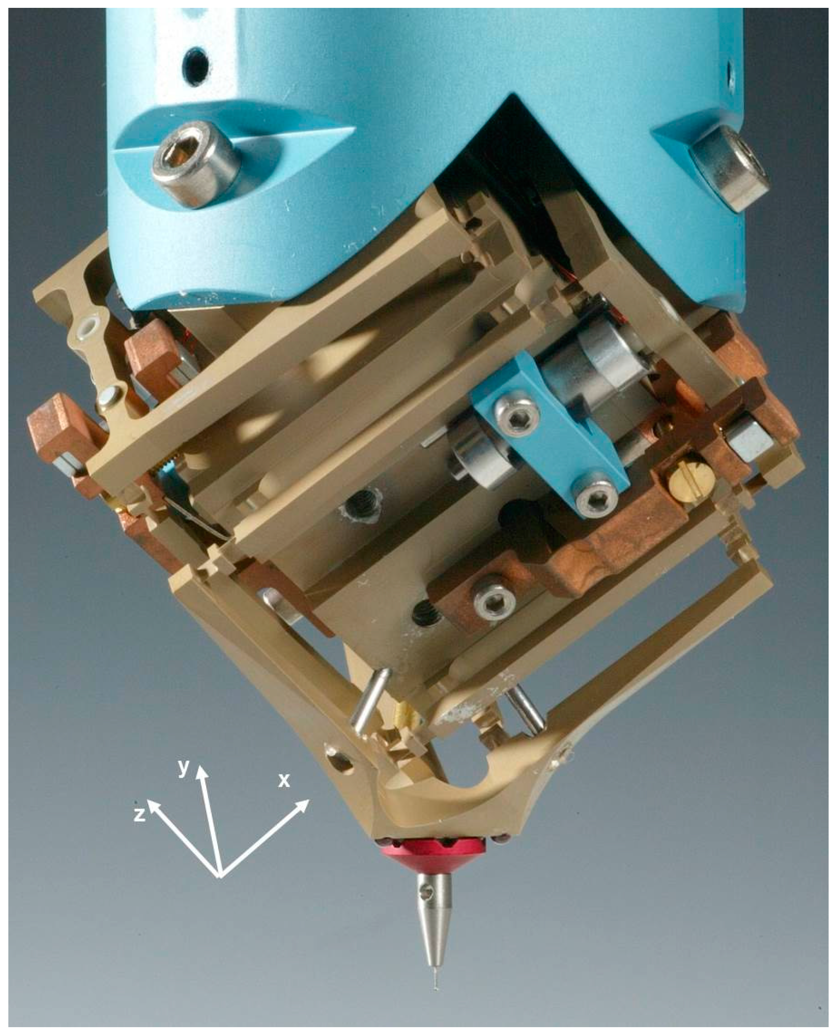
Figure 2.
Principle of measurement stages (2D case for simplification of drawing). (left) Laser interferometer scales and moving workpiece stage with reference mirror frame; (right) Incremental scales and moving probe stage with additional bearings between frames.
Figure 2.
Principle of measurement stages (2D case for simplification of drawing). (left) Laser interferometer scales and moving workpiece stage with reference mirror frame; (right) Incremental scales and moving probe stage with additional bearings between frames.

Figure 3.
Principle of the Abbe free CMM stage at METAS. y-axis perpendicular to drawing plane.
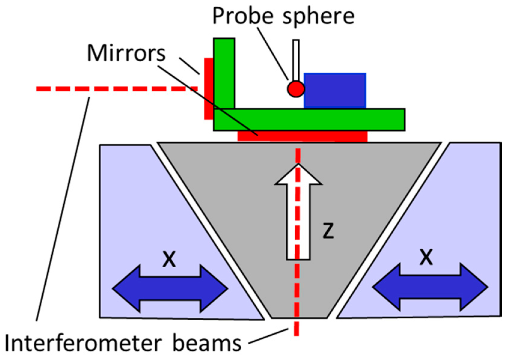
Figure 4.
Determination of the single point probing error according to ISO 10360-5 on a 1 mm Si3N4 sphere: (left) Arrangement of probing points on the reference sphere; (right) Deviation from average radius for four measurements with sphere rotated by 90°.
Figure 4.
Determination of the single point probing error according to ISO 10360-5 on a 1 mm Si3N4 sphere: (left) Arrangement of probing points on the reference sphere; (right) Deviation from average radius for four measurements with sphere rotated by 90°.
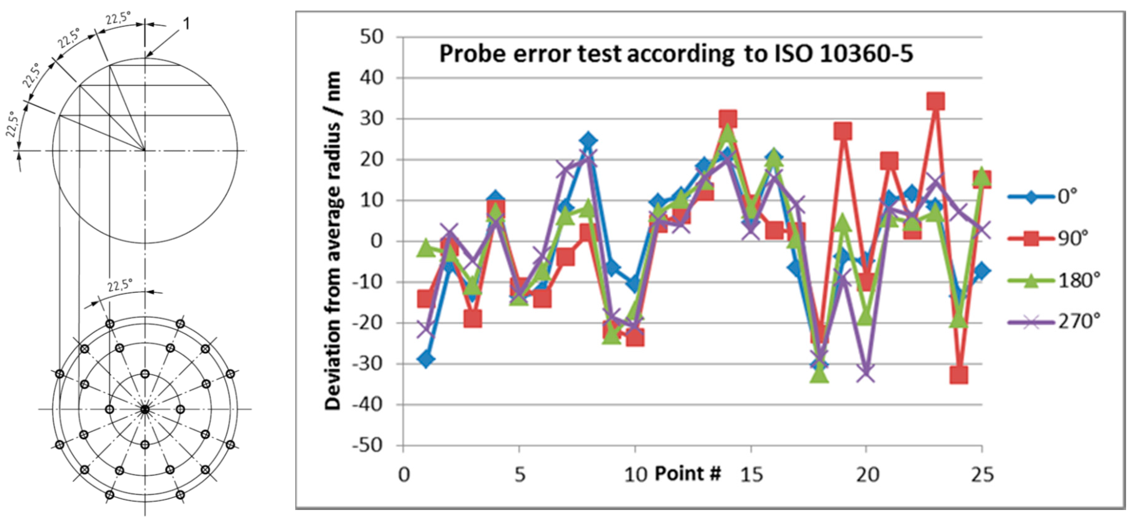
Figure 5.
Determination of the single point probing error according to ISO 10360-4 on a 1 mm ruby sphere: (left) Arrangement of scanning profile planes A, B, C and D; (right) Measured profiles A to D resulting in a scanning probing error Tij = 87 nm.
Figure 5.
Determination of the single point probing error according to ISO 10360-4 on a 1 mm ruby sphere: (left) Arrangement of scanning profile planes A, B, C and D; (right) Measured profiles A to D resulting in a scanning probing error Tij = 87 nm.

Figure 6.
Sphericity map of a 1 mm ruby sphere with 33 nm form deviation. The 3D plot shows results obtained by probing the surface with a 10° resolution in longitude and a 5° resolution in latitude.
Figure 6.
Sphericity map of a 1 mm ruby sphere with 33 nm form deviation. The 3D plot shows results obtained by probing the surface with a 10° resolution in longitude and a 5° resolution in latitude.
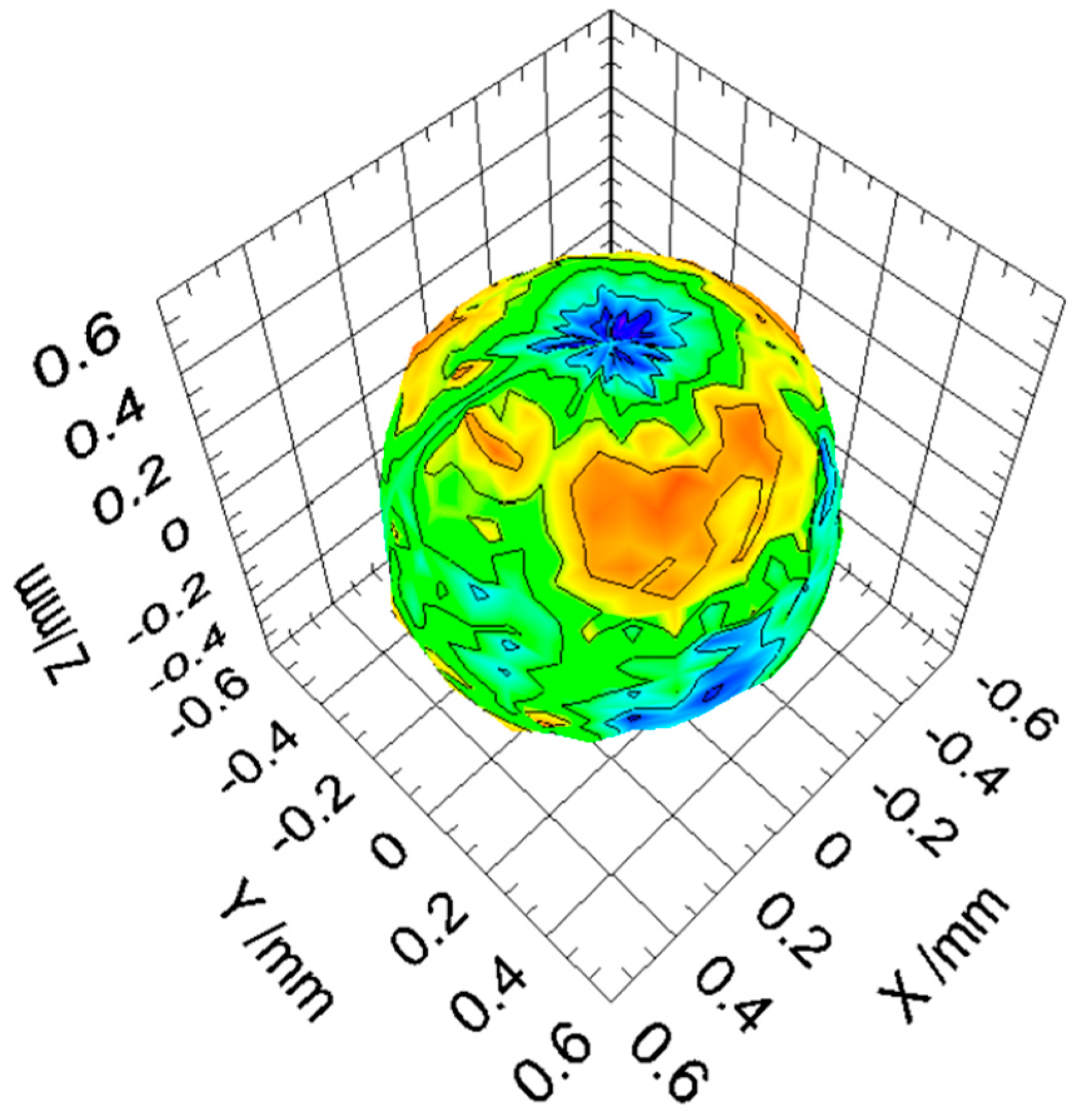
Figure 7.
(left) Micro ball bars used for performance verification; (right) Length deviations measured with 5 different ball bars each oriented in different axial and diagonal directions. Red squares denote the symmetric 95% confidence intervals, red lines the fitted 95% confidence length measurement error E0 = 27 nm + 0.2 × 10⁻⁶ × L.

Figure 8.
(left) Micro ball plate used for performance verification; (right) Deviations measured for 25 ball center positions in four different orientations of the ball plates. The evaluation of all relative ball distances results in a 95% confidence length measurement error of E0 = 26 nm + 0.23 × 10⁻⁶ × L.

© 2016 by the authors; licensee MDPI, Basel, Switzerland. This article is an open access article distributed under the terms and conditions of the Creative Commons Attribution (CC-BY) license (http://creativecommons.org/licenses/by/4.0/).
Share and Cite
MDPI and ACS Style
Thalmann, R.; Meli, F.; Küng, A. State of the Art of Tactile Micro Coordinate Metrology. Appl. Sci. 2016, 6, 150. https://doi.org/10.3390/app6050150
AMA Style
Thalmann R, Meli F, Küng A. State of the Art of Tactile Micro Coordinate Metrology. Applied Sciences. 2016; 6(5):150. https://doi.org/10.3390/app6050150
Chicago/Turabian StyleThalmann, Rudolf, Felix Meli, and Alain Küng. 2016. "State of the Art of Tactile Micro Coordinate Metrology" Applied Sciences 6, no. 5: 150. https://doi.org/10.3390/app6050150
Note that from the first issue of 2016, this journal uses article numbers instead of page numbers. See further details here.