Article

Development of Intelligent Fuzzy Controller for a Two-Axis Solar Tracking System

1
Automation and Control Engineering, Far East University, No. 49, Zhonghua Rd., Xinshi Dist., Tainan 74448, Taiwan
2
Electronic and Optoelectronic Application Engineering, Far East University, No. 49, Zhonghua Rd., Xinshi Dist., Tainan 74448, Taiwan
*
Author to whom correspondence should be addressed.
These authors contributed equally to this work.
Appl. Sci. 2016, 6(5), 130; https://doi.org/10.3390/app6050130
Submission received: 25 November 2015 / Revised: 21 April 2016 / Accepted: 23 April 2016 / Published: 3 May 2016

Abstract

:
This paper proposes the development of a two-axis sun tracking solar energy system using fuzzy logic as intelligent quality policy. To achieve maximum efficiency for solar panels, it is necessary to follow the sun’s path in the sky. Therefore, the architecture for the two-axis sun tracking solar energy system uses software to control the hardware. The hardware comprises (i) solar cells; (ii) lead-acid batteries; (iii) a gear box; (iv) a stepping motor; and (v) a light detection circuit, while the software comprises (i) a detection system; (ii) a fuzzy tracking controller; and (iii) a database system. A fuzzy logic controller is designed as the software architecture of the system to decide the timing for tracking the sun. The nearest position that results in receiving direct sunlight is obtained from the database. Our system is fully automatic in a changing environment and takes into account meteorological changes and the effects of the external environment arising from a malfunction. This approach reduces the number of starting motors and results in smaller energy loss in cloudy, cloud mask, or unstable weather conditions.

1. Introduction

Humankind is facing an energy crisis. It is estimated that the Earth’s coal reserves will last only another hundred years, while petroleum and gas will last even less. This has led, in recent decades, to the development of green and alternative energy resources. One key requirement is that these technologies should save energy without reducing the quality of life or economic growth [1,2].
The use of renewable energy, such as solar energy, wind power, water power, tidal power, sea temperature difference, geothermal energy, and biomass energy is considered essential for sustainable development and is an active research area [3,4]. In Taiwan, wind and solar power are potentially the most important renewable energy sources. To keep noise levels low, wind power systems are only practical in the outskirts of cities, and for economic feasibility, they need to be built on a large scale [5,6]. Another source of renewable energy with great potential is solar energy; the amount of solar energy reaching the Earth in 40 min is equal to humankind’s annual energy requirement. Taiwan is located in the subtropical region close to the equator and it thus receives sufficient sunshine. Solar energy is a clean energy source, and we believe that developing solar energy is a reasonable solution to meeting Taiwan’s energy needs [7,8,9].
Overview of the study: Tracking the sun’s trajectory in the sky and aligning the solar energy system with it can greatly improve the performance. Professor Ozcelik et al. [10] proposed to use a solar tracker which orients itself along the direction of the sunlight, and the solar tracker positions the panel in a hemispheroidal rotation to track the movement of the sun and thus increase the total electricity generation. Roshan et al. [11] reported that using tracking functional solar cells can increase the output by 50% compared to a fixed system. This necessitates the use of a two-axis tracking system. The system needs to drive two sets of motors to control the angle of the solar panels, which increases hardware costs and electrical energy consumption. Professor Huang [12] of Kaohsiung University of Applied Sciences has studied one-axial and two-axial tracking systems in detail. This article proposes the application of fuzzy control theory in a solar tracking system, which is fully automatic in a changing environment, and which takes into account meteorological changes and the external environment arising from a malfunction. This approach avoids cloudy skies, cloud cover, and unstable weather to reduce unnecessary energy loss. The database associated with the elevation and horizontal angle of the solar cells is used to achieve the best quality of the effect of charging the system.

2. Hardware Framework of Sum Track System

2.1. Solar Cell

Solar cells can be divided into two types: Bulk Type and Thin Film Type. Solar cells are made of different materials and have different values of efficiency. Table 1 shows the efficiencies of different materials used in solar cells. Based on cost and generation efficiency, we choose monocrystalline silicon to perform the experiments [13,14,15].

2.2. Lead-Acid Battery

To test the efficiency of the sun tracking system, a battery is needed to store energy. Considering cost and efficiency, we choose a lead-acid battery for this study. Lead-acid batteries are rechargeable, long-life and high-performance batteries used in many applications [16]. Figure 1 shows the structure of a lead-acid battery.

2.3. Reducer

Figure 2 shows a gear reducer, worm and worm structure. The worm is the helical gear, and at least one tooth along its cylindrical wrap is spiral in shape. It is used in gear transmission and can convey a set of disjoints that are at right angles to each other and have a high speed ratio of the two axes of power (in the space between two orthogonal axes).

2.4. Stepping Motor

The stepping motor, which is dual-axis control, is used in the precise angle positioning and control of intermittent rotation. It has the following advantages [17,18]:
(1)
The digital signal can be directly controlled by Open Loop, rather than by a complex feedback control. Thus, the system is simple.
(2)
The rotational speed changes with the input pulse frequency, and it is therefore easy to control the motor acceleration and deceleration.
(3)
It is easy to start, has a good reaction to stopping, reversing, and speed changing.
(4)
The rotation angle of the motor and the input pulse is proportional to the ratio. The error is minor, and is not cumulative.
(5)
It has a low-speed, high torque rotation, and is brushless. It has a wide range of applications and high reliability.

2.5. Photo Detection Circuit

The purpose of the photo detection circuit is to detect the illumination produced by the sun. Figure 3 shows the voltage divider and bias circuits. The main parts of the circuit are the dark current compensation circuit, the base for using optical crystal with the temperature compensation circuit, and a voltage divider bias circuit. The temperature compensation effect of the DC action and the DC operating point result in good thermal stability. The base current is also included to reduce the role of the dark current so that the light metering device can also be used for analog applications.

3. Intelligent Fuzzy Logic Controller

Zadeh [19] proposed a quantitative tool in 1965, which can be used to express an ambiguity concept, especially in the ambiguity of human language. Sugeno carried out further research in this area. The result of their work is the fuzzy logic controller (FLC), which has now become world famous [20,21,22]. The main advantage of the FLC is that it can be applied in situations where the controlled body is too complex or difficult to be mathematically modeled. The design of the controller is based on a few fuzzy rules. Thus, the FLC is smart and user-friendly.
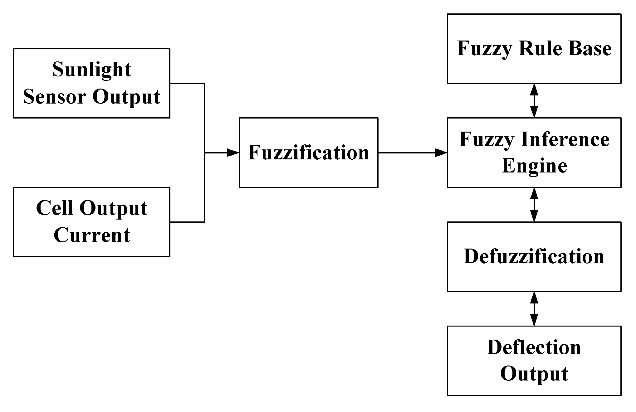
Generally speaking, the operation of the FLC can be divided into four areas: (1) fuzzification; (2) decision-making logic; (3) fuzzy knowledge base; and (4) defuzzification. Fuzzification is the process that converts numerical values into grades of membership of fuzzy set members. Hence, the fuzzification block matches the input data to determine how well the condition of each rule matches that particular input. A degree of membership function for each linguistic term applies to the input variable. We apply this system in the FLC solar panel output current and define the sunlight sensor output voltage values. The fuzzy inference engine provides the input values (as shown in Figure 4). The use of fuzzy sets is defined, the membership functions are quantified, and continuous use of the triangular membership functions is made to reduce errors. Table 2 presents the variables used for fuzzy logic control.
Table 3 shows the membership functions for the input variables (sunlight voltage and cell current).
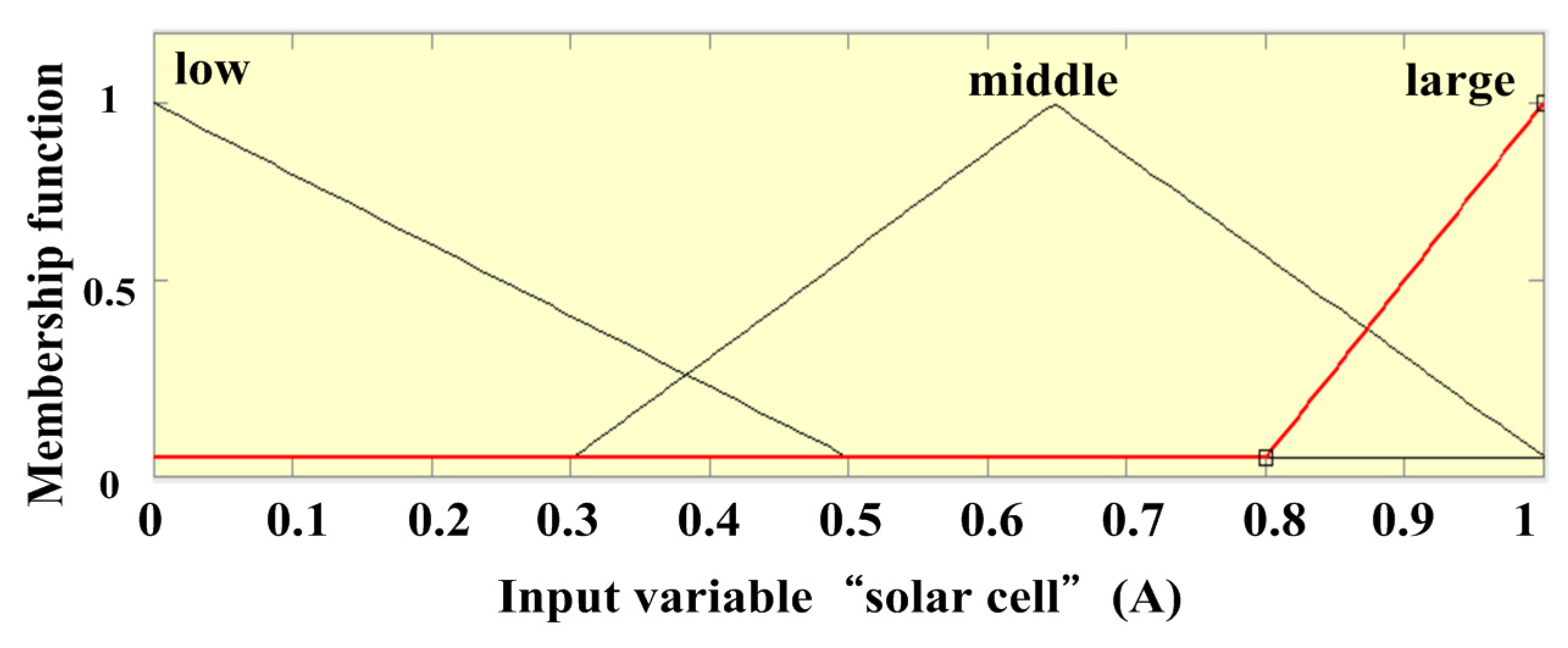
Figure 5, Figure 6 and Figure 7 show the membership functions for the front and rear pieces. The front pieces of the system are the output current of the solar panel and the output voltage of photo detection (for the intensity of sunlight). The rear piece is the output for the rotation of the solar panels. By the triangle consisting of the ownership function, the function values of each point are between 0 and 1, corresponding to each input variable value, in which the horizontal coordinates for the input variable value is also known as the collection element. The ordinate represents the size of the element, also known as the degree of ownership. Among them, sunlight intensity can be divided into three states: large, medium and small; the solar panel current can be divided into three states: large, medium and small; and the output value can be divided into three states: large, medium and small.
The second step of the fuzzy controller design is to determine the form of fuzzy rules and list all the relevant rules. It refers to the relationship of solar cell output current and illumination of sunshine, and past data obtained from the literature, and relevant experts, to establish the following fuzzy rule base. The control rules are evaluated by an inference mechanism and represented as a set of: IF Sunlight sensor voltage is … and Cell current is … THEN the output will …
For example, Rule 1: IF sunlight sensor voltage is Small and Cell current is Small THEN the output is Low (stop). The linguistic variables used are Low (stop) and Large (start), as shown in Table 4.
The third step of the fuzzy controller design is deciding what kind of fuzzy inference engine should be used. For this system, the maximum/minimum is selected as the synthetic fuzzy inference method [23,24,25]. Figure 8 shows the operation of the fuzzy inference engine, which assumes that the input value (3.5 V) of sunlight intensity triggers three rules, and the one triggered by a high degree of fuzzy set intersections has been truncated (yellow area). For the first rule of fitness, the solar panel input current (0.377 A) triggered six rules. The one triggered by a high degree of fuzzy set intersections has been truncated (yellow area). The output of the fuzzy set is taken as the Y-intersection and the fuzzy set of the final will be the union of the most fuzzy sets.
The whole process of computing algorithms uses Equations (1)–(3). The input variables are V (sunlight intensity), I (solar panel current), and the fitness of the front pieces (W). B is the fitness of the rear pieces after the piece for the department of fitness [26]. The fitness of the front pieces is given by:
  W i = M i n { m a x [ m i n ( V a i ,   V a ' ) ] m a x [ m i n ( I b i , I b ' ) ] }
The fitness of rear pieces is given by:
B i ' = m i n ( W i μ B i ' ( y ) )
where i is number of rule, V a ' and I b ' are input, and μ is output. For the entire rule set:
B = M a x i = 1 r B i '
where r is the number of triggered rules. This paper uses the focus-center method to defuzzify serial values as shown below:
U * = μ ( y ) × y d y μ ( y ) d y
The calculation time can be shortened using the topology method. The output area Y is classified into p numbers of discrete values, which can be expressed as Y = {y1, y2, y3, …, yp}. Thus, the focus-center method can be shown as:
U * = j = 1 p y i × μ ( y i ) j = 1 p μ ( y i )
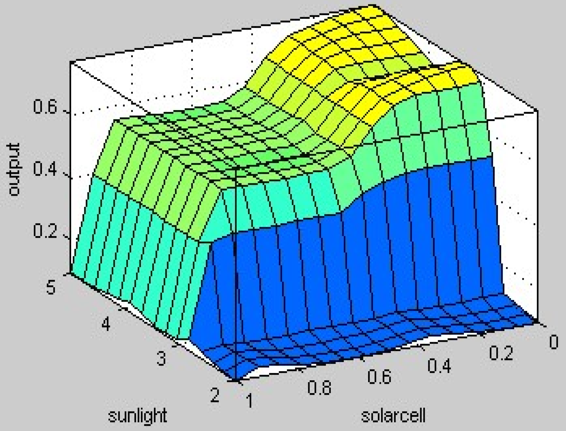
In this paper, we use MATLAB Fuzzy Logic Toolbox (R2012a, MathWorks, Natick, MA, USA, 2012) to find the fuzzy controller output value, as shown in Figure 8, and determine its output value to determine the solar panels’ action. Then, we determine its output value to determine whether solar panels on the action. This research sets the fuzzy output value of 0.5 (or more) for the solar panels needed to track the sunshine. If below 0.5, rotating solar panels are not needed. Rotating solar panels are then calculated using the current database theory to get what is the angle of the sun.
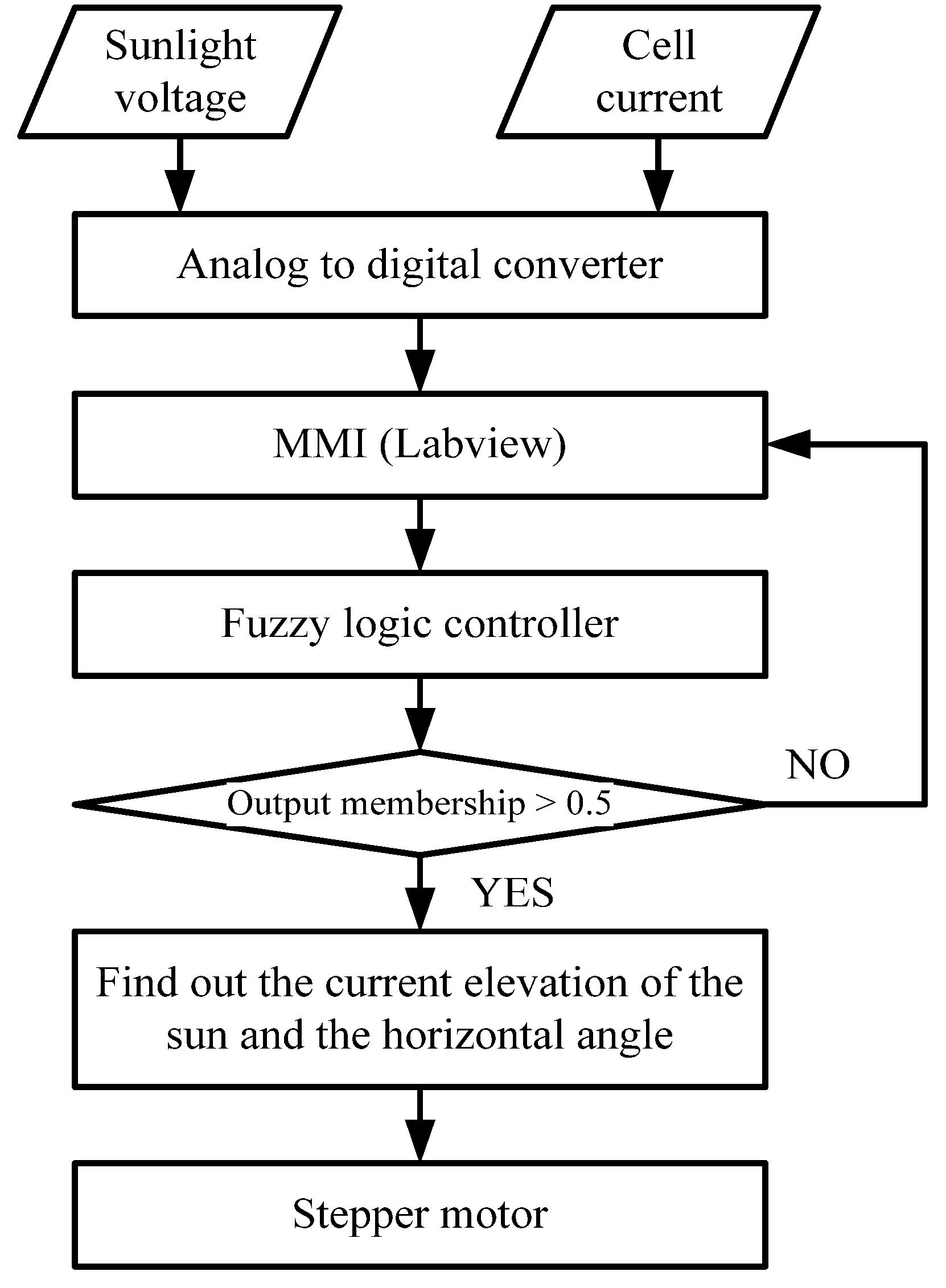
For axial tracking, the stepper motor is used as a driving source to rotate the solar panel in the direction of the sun. The position of the sun is determined by a fuzzy program with two input items (sunlight sensor voltage and solar cell current) and one output item (stepper motor). The sensor voltage and cell current reading is then converted into digital form using an analog-to-digital converter (ADC) and passed onto the FLC for aligning the panel in the direction of the sun. The FLC’s output is connected to the driver of the stepper motor to rotate the panel on one axis until it faces the sun through a gear box. The flowchart in Figure 9 describes the control algorithm based on fuzzy logic, which is used to implement the system.

4. Sun Track System Software

4.1. System Programming

This paper proposes the design of system software using LabVIEW (2012, National Instruments, Austin, TX, USA, 2012) and MATLAB (R2012a, MathWorks, Natick, MA, USA, 2012). Real-time detection software is written in LabVIEW. The intensity of the sunlight and the solar panel output current are passed through an A/D converter and fed to the computer’s serial port to enter the PC. These two variable values, through the FUZZY program of MATLAB, determine whether the solar panels need to be rotated or not. If they do not need to be rotated, we return to LabVIEW for detection. If they need to be rotated, we start the search of the database. The current position of the sun and its horizontal angle is then found, and the angle values of X and Y are passed to the main LabVIEW program to calculate the required pulse number to drive the stepper motor. Through the data line of the Print Port, the Darlington circuit of the stepper motors is driven to rotate the stepper motor. The worm gear reducer enables the rotating solar panel to follow the sun’s path. Therefore, the solar cells receive the sunlight directly, resulting in an increased generating capacity.

4.2. Two-Axis Angle Control

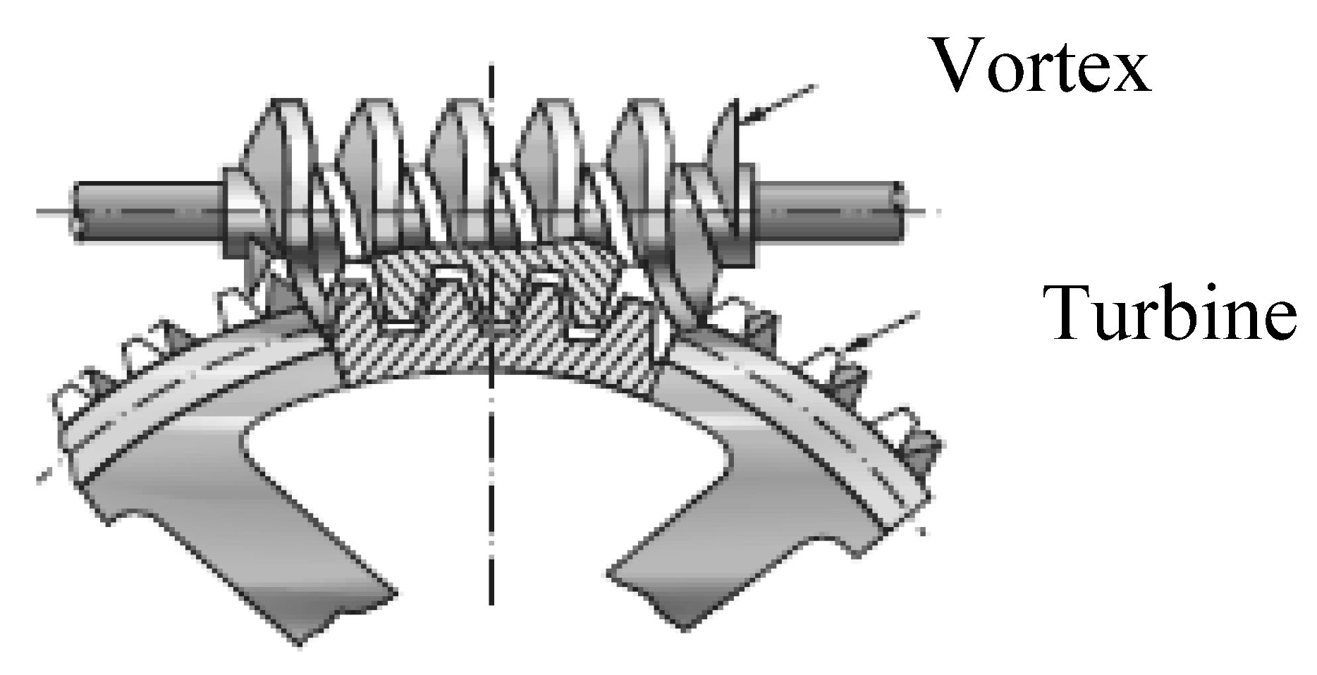
In solar elevation angle control, the reducer is used vertically (5:1) to rotate the stepping motor’s downwards. This changes the y-axis height and the elevation angles α, because an increase in the y-axis results in a circular motion. This experiment thus uses a horizontal slide to mitigate this issue. The solution involves installing a mobile slide on the bottom of the elevator base, which changes its circumferential force and improves the base by changing its elevation angle α. The stepper motors are insufficient to meet the elevator’s high torque requirement, which necessitates the use of a 9:1 gear.
The angle is calculated using the following equation:
tan α = H L
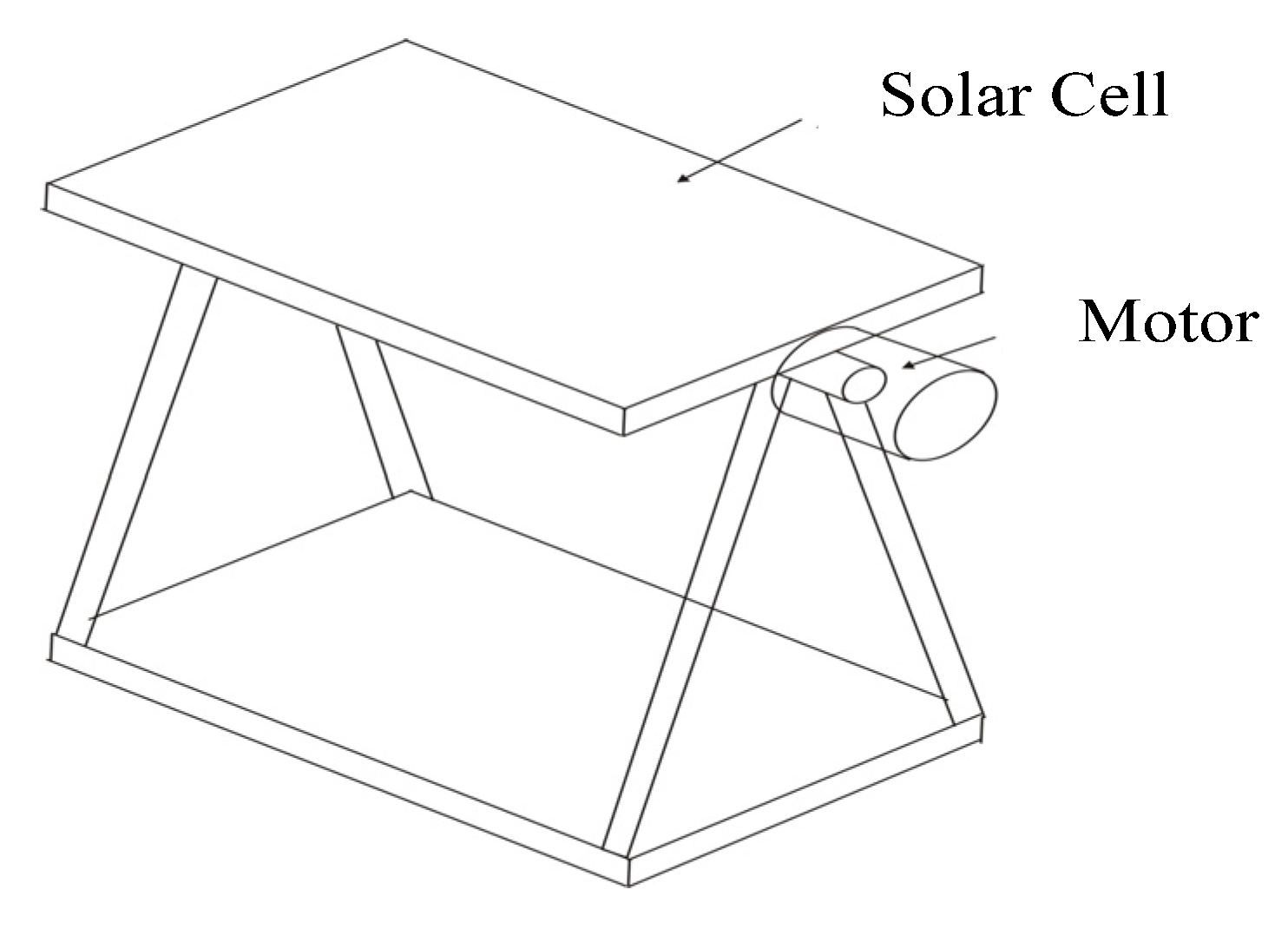
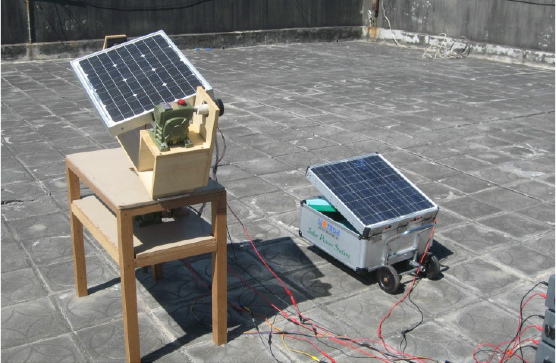
The installed solar panels are connected to the reducer’s output side (30:1) and then directly to the stepper motor from the power side of the reducer. The reducer can accurately control the solar panels and guard them against wind and vibrations (Figure 10).
In this study, the two-phase stepper motor controls the angle of excitation. The value is 0.9 degrees per step, plus gear (30:1); therefore, for every step, the stepper motor controls the angle of the solar panels by 0.03 degrees. The horizontal angle control of the system can be expressed using the following relation:
θ = P × 0.9 30

5. Result Analysis

As previously mentioned, the sun tracking solar system is written in LabVIEW, while the fuzzy control algorithm is written in MATLAB. The solar panels, personal computers, and hardware mentioned above are integrated as shown in Figure 11.

5.1. Fuzzy Test

The fuzzy logic control uses the current produced in the solar panels by the sunlight to determine the timing for activating the motor to drive the solar panels to the correct position. For the fuzzy programming part, we assume that the output voltage of light intensity is 2.5 V to 4.5 V and the output current of the solar panels is 0.1 A to 1 A. The outputs of the fuzzy programming tests are recorded in Table 5. The highlighted part is required to start the motor. The results show that if the output value is greater than 0.5, the motor of the sun tracking system needs to be started; if it is less than 0.5, the solar panels maintain the original position.

5.2. Comparison Analysis of Output Power

Two solar energy systems are set up for the test mentioned above. One is fixed at an elevation angle of 23.5 degrees, while the other tracks the sun. After eight hours of sunshine, the fixed-angle solar energy system has an average output current of 0.58 A, while the intelligent sun tracking solar energy system has an output average current of 0.94 A, indicating a difference of 0.36 A. Thus, the intelligent sun tracking solar energy system has an increased capacity of 36%, an increased power of 4.32 W, and an increase in total energy of 34.56 watt-hours (Table 6).

5.3. Energy Loss Analysis of Step Motor

The stepper motor’s voltage and current are 4 V, 1.0 A, respectively, and its power consumption is 4.0 W. As the design uses worm gear, it does not need to maintain the torque of the stepper motor. This results in an energy saving of about 35.2 watt-hours. The rotation of solar panels from 0° to 180° takes 30 s for a one-way trip and one minute for a round trip. Therefore, the total energy consumption of the stepper motor of the sun tracking system is 0.073 watt-hours a day. Controlling the stepper motor’s elevation angle from 0° to 46° takes 1 h 35 min and 31 s. Thus, the stepper motor needs a round-trip for a year, and its total energy consumption is 14.08 watt-hours. The average energy consumption is 0.038 watt-hours a day (Table 7). By using fuzzy logic control to detect the sunshine and solar panel current every two minutes for eight hours of testing, the stepper motor starts 33 times with equal recovery times of two minutes. The stepper motor starts 240 times. Therefore, using fuzzy logic control can effectively reduce the number of motor starts.

6. Conclusions

This study proposed a two-axis sun tracking solar energy system using fuzzy logic as an intelligent quality policy. In the fuzzy logic control based sun tracking solar system, the hardware is based on the dual-axis solar panels to achieve mechanical movement. The software application of fuzzy logic controls the decision of the timing of sun tracking and database theory, and associates them with the position closest to direct sunlight. Compared to traditional sensor sun tracking systems, this system is more accurate as it is easier to control the angle, and the circuit design is simpler, without considering the error caused by external environment changes. We also propose equipping a photo detection circuit. Even in poor weather conditions when the solar cells are covered by other external factors or when the sun’s luminosity is low, it can reduce the number of times the motor starts and thus reduce unnecessary energy loss.

Acknowledgments

We would like to thank the Ministry of Science and Technology of the Republic of China, Taiwan (Contract No. MOST 103-2221-E-269-011).

Author Contributions

C.-H. Huang conceived and designed the experiments; H.-Y. Pan performed the experiments; C.-H. Huang and K.-C. Lin analyzed the data; C.-H. Huang wrote the paper.

Conflicts of Interest

The authors declare no conflict of interest.

References

  1. Popoola, O.M. Clément Burnier. Solar water heater contribution to energy savings in higher education institutions: Impact analysis. J. Energy S. Afr. 2014, 25, 51–58. [Google Scholar]
  2. Redpath, D. Thermosyphon heat-pipe evacuated tube solar waters for northern maritime climates. Sol. Energy 2012, 86, 705–715. [Google Scholar] [CrossRef]
  3. Yao, Y.X.; Hu, Y.; Gao, S.; Yang, G.; Du, J. A multipurpose dual-axis solar tracker with two tracking strategies. Renew. Energy 2014, 72, 88–98. [Google Scholar] [CrossRef]
  4. Li, P.W.; Kane, P.; Mokler, M. Modeling of solar tracking for giant Fresnel lens solar stoves. Sol. Energy 2013, 96, 263–273. [Google Scholar] [CrossRef]
  5. Milutinović, M.; Čorić, M.; Deur, J. Operating cycle optimization for a Magnus effect-based airborne wind energy system. Energy Convers. Manag. 2015, 90, 154–165. [Google Scholar] [CrossRef]
  6. Lam, J.C.K.; Woo, C.K.; Kahrl, F.; Yu, W.K. What moves wind energy development in China? Show me the money! Appl. Energy 2013, 105, 423–429. [Google Scholar] [CrossRef]
  7. Hürdoğan, E.; Büyükalaca, O.; Yılmaz, T.; Hepbasli, A.; Uçkan, İ. Investigation of solar energy utilization in a novel desiccant based air conditioning system. Energy Build. 2012, 55, 757–764. [Google Scholar] [CrossRef]
  8. Gomesh, N.; Daut, I.; Irwanto, M.; Irwan, Y.M.; Fitra, M. Study on Malaysian’s perspective towards renewable energy mainly on solar energy. Energy Procedia 2013, 36, 303–312. [Google Scholar] [CrossRef]
  9. Julajaturasirarath, S.; Jonburom, W.; Pornsuwancharoen, N. The experiment of double solar energy by reflection light method. Procedia Eng. 2012, 32, 522–530. [Google Scholar] [CrossRef]
  10. Ozcelik, S.; Prakash, H.; Challoo, R. Two-Axis Solar Tracker Analysis and Control for Maximum Power Generation. Procedia Comput. Sci. 2011, 6, 457–462. [Google Scholar] [CrossRef]
  11. Roshan, Y.M.; Moallem, M. Maximum power point estimation and tracking using power converter input resistance control. Sol. Energy 2013, 96, 177–186. [Google Scholar] [CrossRef]
  12. Huang, B.J.; Ding, W.L.; Huang, Y.C. Long-term field test of solar PV power generation using one-axis 3-position sun tracker. Sol. Energy 2011, 85, 1935–1944. [Google Scholar] [CrossRef]
  13. Lee, J.; Jung, Y.K.; Lee, D.Y.; Jang, J.W.; Cho, S.; Son, S.; Jeong, J.H.; Park, S.H. Enhanced efficiency of bilayer polymer solar cells by the solvent treatment method. Synth. Met. 2015, 199, 408–412. [Google Scholar] [CrossRef]
  14. Li, Q.; Yuan, Y.; Wei, T.; Li, Y.; Chen, Z.; Jin, X.; Qin, Y.; Sun, W. The origin of efficiency enhancement of inorganic/organic hybrid solar cells by robust samarium phosphate nanophosphors. Sol. Energy Mater. Sol. Cells 2014, 130, 426–434. [Google Scholar] [CrossRef]
  15. Borra, M.Z.; Güllü, S.K.; Es, F.; Demircioğlu, O.; Günöven, M.; Turan, R.; Bek, A. A feasibility study for controlling self-organized production of plasmonic enhancement interfaces for solar cells. Appl. Surf. Sci. 2014, 318, 43–50. [Google Scholar] [CrossRef]
  16. Albers, J.; Meissner, E.; Shirazi, S. Lead-acid batteries in micro-hybrid vehicles. J. Power Sources 2011, 196, 3993–4002. [Google Scholar] [CrossRef]
  17. Ting, C.S.; Chang, Y.N. Observer-based back stepping control of linear stepping motor. Control Eng. Pract. 2013, 21, 930–939. [Google Scholar] [CrossRef]
  18. Qi, F.Q.; Jing, X.D.; Zhao, S.Q. Design of stepping motor control system based on AT89C51 microcontroller. Procedia Eng. 2011, 15, 2276–2280. [Google Scholar]
  19. Zadeh, L.A. Fuzzy sets. Inf. Control 1965, 8, 338–353. [Google Scholar] [CrossRef]
  20. Bouchafaa, F.; Hamzaoui, I.; Hadjammar, A. Fuzzy logic control for the tracking of maximum power point of a PV system. Energy Procedia 2011, 6, 633–642. [Google Scholar] [CrossRef]
  21. Subiyanto, S.; Mohamed, A.; Hannan, M.A. Intelligent maximum power point tracking for PV system using Hopfield neural network optimized fuzzy logic controller. Energy Build. 2012, 51, 29–38. [Google Scholar] [CrossRef]
  22. Rajesh, R.; Mabel, M.C. Efficiency analysis of a multi-fuzzy logic controller for the determination of operating points in a PV system. Sol. Energy 2014, 99, 77–87. [Google Scholar] [CrossRef]
  23. Rizwan, M.; Jamil, M.; Kirmani, S.; Kothari, D.P. Fuzzy logic based modeling and estimation of global solar energy using meteorological parameters. Energy 2014, 70, 685–691. [Google Scholar] [CrossRef]
  24. Zhai, P.; Williams, E.D. Analyzing consumer acceptance of photovoltaics (PV) using fuzzy logic model. Renew. Energy 2012, 41, 350–357. [Google Scholar] [CrossRef]
  25. Shieh, C.S. Fuzzy PWM based on genetic algorithm for battery charging. Appl. Soft Comput. 2014, 21, 607–616. [Google Scholar] [CrossRef]
  26. Seera, M.; Lim, C.P.; Loo, C.K.; Singh, H. A modified fuzzy min-max neural network for data clustering and its application to power quality monitoring. Appl. Soft Comput. 2015, 28, 19–29. [Google Scholar] [CrossRef]
Figure 1. The structure of a lead-acid battery.
Applsci 06 00130 g001
Figure 2. Vortex and turbine.
Applsci 06 00130 g002
Figure 3. The photo detection circuits.
Applsci 06 00130 g003
Figure 4. Framework of fuzzy logic control method.
Applsci 06 00130 g004
Figure 5. Membership function of sunlight.
Applsci 06 00130 g005
Figure 6. Membership function of the output current.
Applsci 06 00130 g006
Figure 7. Membership function of the consequent part.
Applsci 06 00130 g007
Figure 8. 3D output figure.
Applsci 06 00130 g008
Figure 9. Flowchart of solar tracking system.
Applsci 06 00130 g009
Figure 10. Sun track system diagram.
Applsci 06 00130 g010
Figure 11. Hardware device of sun track system.
Applsci 06 00130 g011
Table 1. Comparison of solar cell efficiency.
Solar Cell InformalMonomer Efficiency (%)Module Efficiency (%)
Monocrystalline silicon2210–15
Polycrystalline silicon189–12
Boron-Phosphorus compound3017
ThinFilm Amorphous Silicon1310
ThinFilm Cu-In1912
ThinFilm Cd-Te compound169
Table 2. Fuzzy variables.
ItemsInput/OutputMinimum ValueMaximum Value
sunlight voltage (V)Input25
cell current (A)Input01
output membership (%)Output01
Table 3. Membership functions for the input variables.
Fuzzy VariablesCrisp Input Range for Sunlight Voltage (V)Crisp Input Range for Cell Current (A)
Small2.0−3.00−0.5
Middle2.6−4.00.3−1.0
Large3.5−5.00.8−1.0
Table 4. Fuzzy rules.
Sunlight VoltageSmallMiddleLarge
Cell Current
SmallLow (stop)Large (start)Large (start)
MiddleLow (stop)Large (start)Large (start)
LargeLow (stop)Low (stop)Low (stop)
Table 5. Results of fuzzy test.
Sunlight (V)2.533.544.5
Fuzzy
Output Current (A)
0.10.18920.74450.82510.79150.8222
0.20.18920.74450.81680.79150.8168
0.30.20220.73340.79780.79150.7978
0.40.20850.53770.54720.54720.5472
0.50.18920.49240.50000.50000.5000
0.60.18920.49240.50000.50000.5000
0.70.18920.49240.50000.50000.5000
0.80.20850.49040.50000.50000.5000
0.90.19180.19620.19180.20850.1918
1.00.18920.19620.17490.20850.1778
Table 6. Comparison analysis table of output power.
Date: 9 May 2015Fixed Solar Elevation Angle: 23.5°Two-Axis Track Elevation Angle: 5.1°
Average sunlight8 H8 H
Average curent (A)0.58 A0.94 A
Output voltage (V)12 V12 V
Output power (W)6.96 W11.28 W
Output energy (Wh)55.68 Wh90.24 Wh
Table 7. Loss analysis of step motor.
StandardElevation Angle MotorHorizontal Motor
Voltage (V)4 V4 V
Current (A)1.0 A1.0 A
Return time (min)0.521
Loss energy (W-Hours)0.038 Wh0.073 Wh

