1. Introduction
Fire is one of the most severe hazards that building structures may experience during their lifetime [
1]. If a structure is damaged by fire, it is necessary to investigate the cause of the fire and evaluate the reusability of the damaged structure. In terms of economic efficiency, it may be a better approach to retrofit the damaged components of the structure, instead of demolishing it partially or completely. This decision must be made based on the result of investigations such as the visual inspection of the damaged structure, tests on the remaining material, and finite element simulations of the structure or its structural components.
Concrete is a structural material, which performs well under fire conditions due to its low thermal conductivity and incombustibility. Furthermore, a reinforced concrete (RC) structure with proper reinforcement details can effectively redistribute loads from damaged region to undamaged components even if the part of the structure is severely damaged by fire. Therefore, it is not common for fire-damaged RC structures to completely collapse during or after an event of fire [
2].
For this reason, fire-damaged RC structures can be generally rehabilitated by applying proper retrofitting methods. Representative examples of such methods include the strengthening of damaged RC beams and columns with fiber-reinforced polymer (FRP) sheets [
3,
4] and the repair of damaged RC slabs with near-surface mounted carbon FRP rods [
5]. They are sufficiently effective to restore the structural functions of the damaged structural components. In addition, thermo-mechanical finite element analysis is a useful tool to predict the structural behavior and performance degradation of RC structures subjected to fire [
6,
7,
8]. In the case of a special event such as a fire occurrence caused by earthquakes, incremental dynamic analysis can also be performed to evaluate the nonlinear seismic response of fire-weakened RC structures [
9,
10].
Based on this discussion, this paper presents a case study to provide a reference for the rehabilitation of fire-damaged RC structures. The target structure is the main control building of a thermal power plant. The fire broke out in one of battery rooms in the building for an unknown reason and lasted for three hours before it was extinguished. The fire was contained within the battery room and did not spread to the other part of the building. As the power plant was under construction at the time of fire, the building was not in use and there were no casualties due to the fire other than to the building structure. A team of structural and material researchers/engineers was dispatched to the site to evaluate the condition of the structure and to set up appropriate corrective measures. The topics discussed in this paper include the results of the site investigation and tests, and a tentative plan for the rehabilitation of a structure damaged by fire.
2. Visual Inspection of Damaged Structural Components
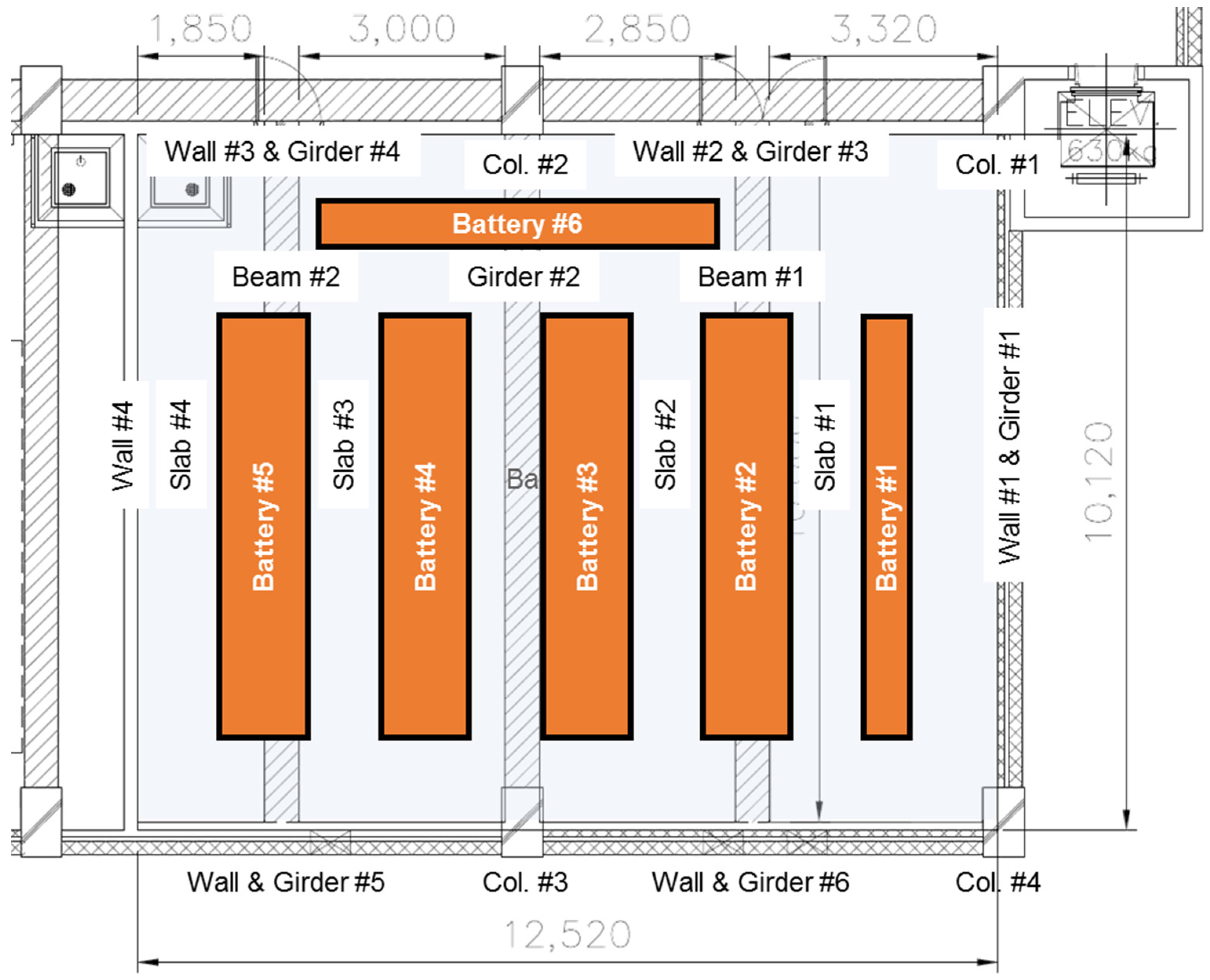
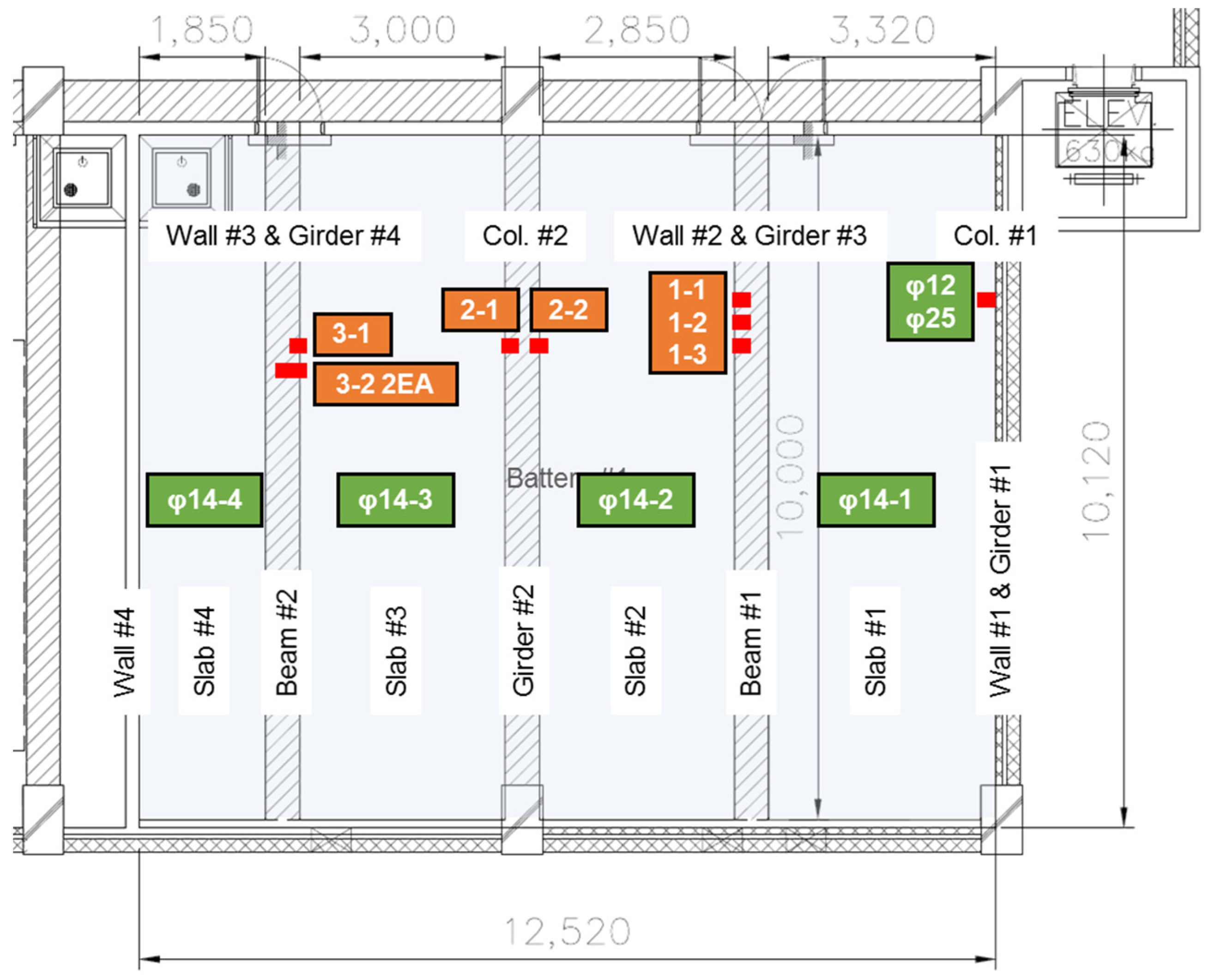
The site investigation was carried out two days after the fire occurrence. The condition of all the main structural components damaged by the fire such as slabs, girders, beams, columns and walls were visually examined. Among them, severely damaged components were categorized. The location and identification number of each structural member are indicated in
Figure 1. Additionally, of interest at first was whether the structural damage involved the possible explosion of batteries. However, no sign of explosion or blast was identified during the investigation.
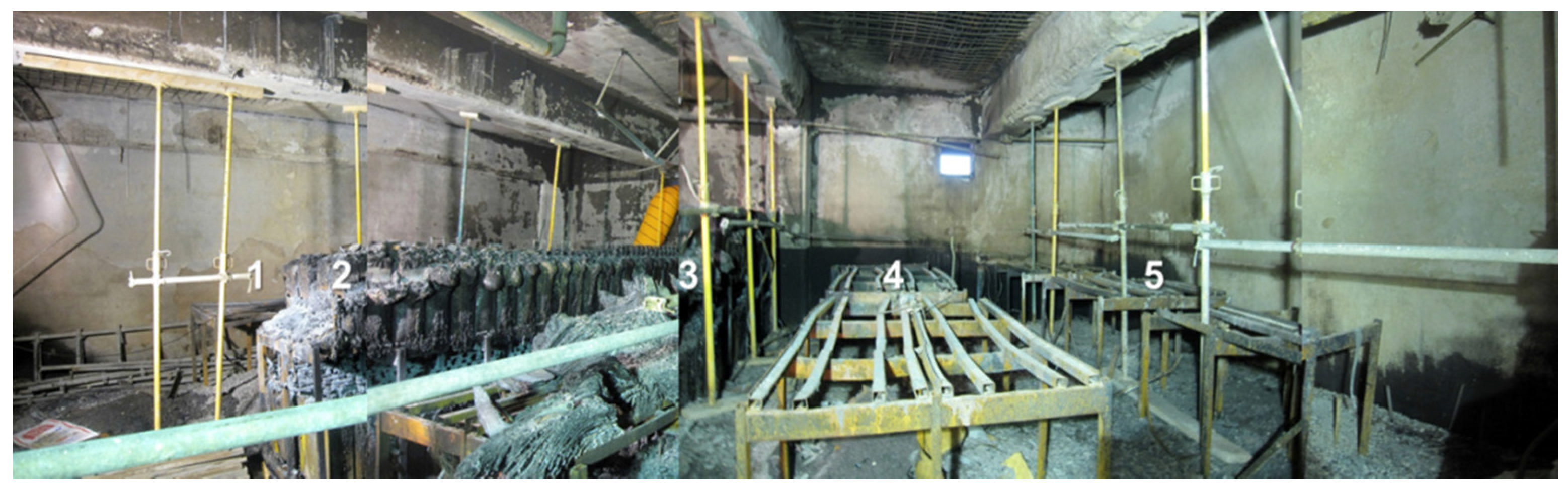
The visual inspection revealed that most of the batteries in the room were burned down, especially the Batteries #1, #4, #5 and #6. For Batteries #2 and #3, part of the battery structures still remained as shown in
Figure 2. This condition coincides with accounts stating that the fire burned longest in the region of Batteries #4 and #5. As a result, the structural elements located above Batteries #1, #4, and #5 experienced relatively severe damage compared with those located above Batteries #2 and #3.
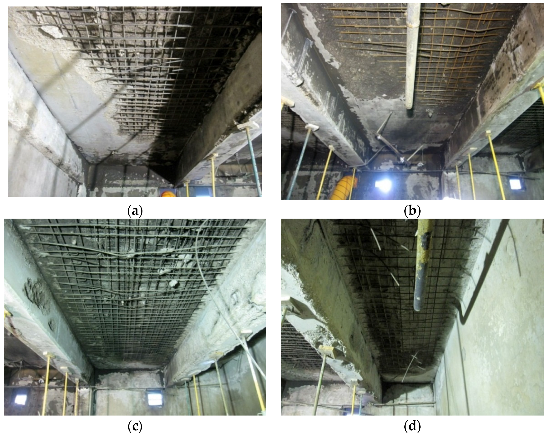
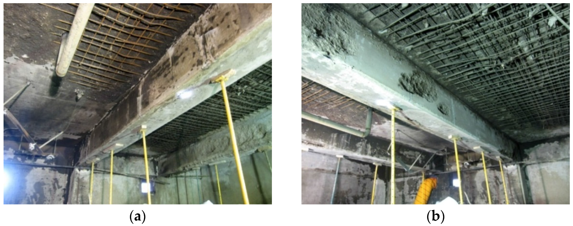
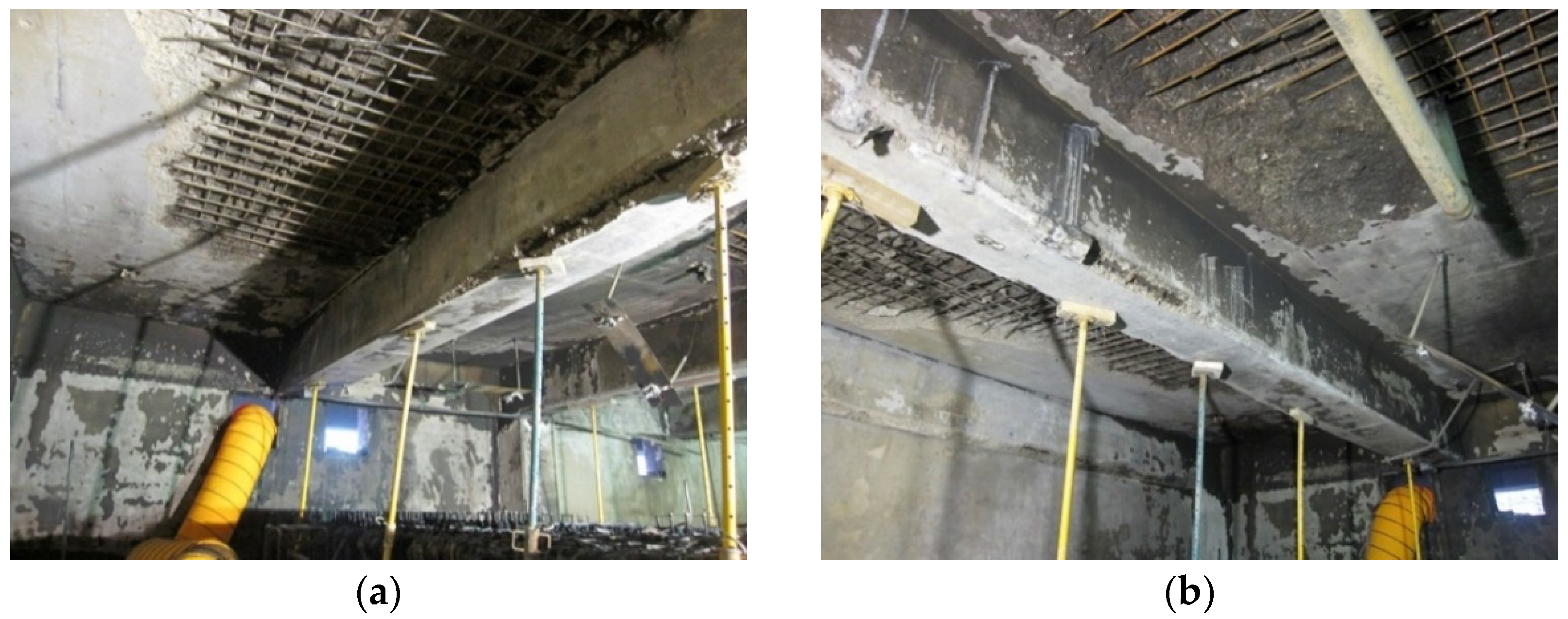
The soffit of the slabs were mostly damaged due to fire as shown in
Figure 3. The concrete in the bottom cover and at mid-depth spalled, exposing the reinforcing bars. The damage was more severe in Slabs #3 and #4 than in Slabs #1 and #2. The condition of each slab can be summarized as below:
Slab #1: More than 50% of the concrete spalled and 60% of bottom reinforcing bars were exposed.
Slab #2: About 50% of the concrete spalled and 50% of bottom reinforcing bars were exposed.
Slab #3: More than 90% of the concrete spalled. About 90% of bottom reinforcing bars and 40% of top reinforcing bars were exposed.
Slab #4: More than 90% of the concrete spalled. About 90% of bottom reinforcing bars and 30% of top reinforcing bars were exposed.
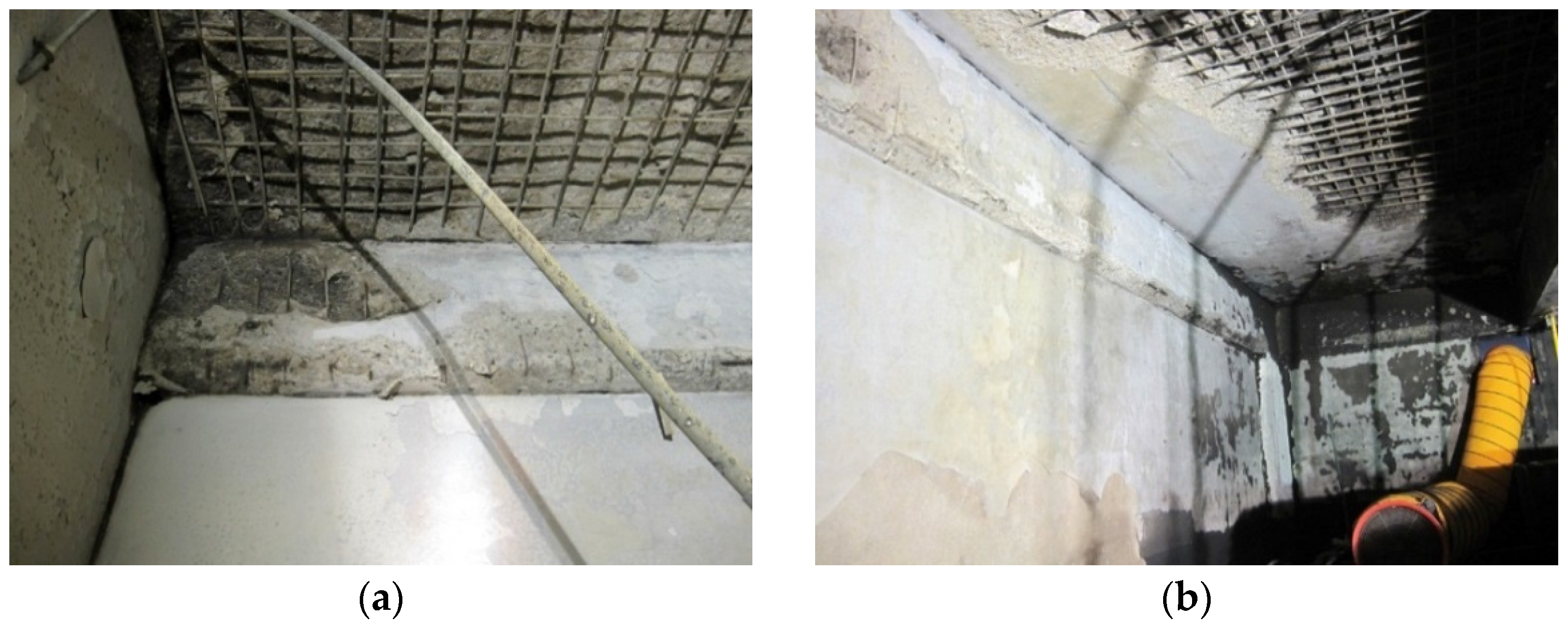
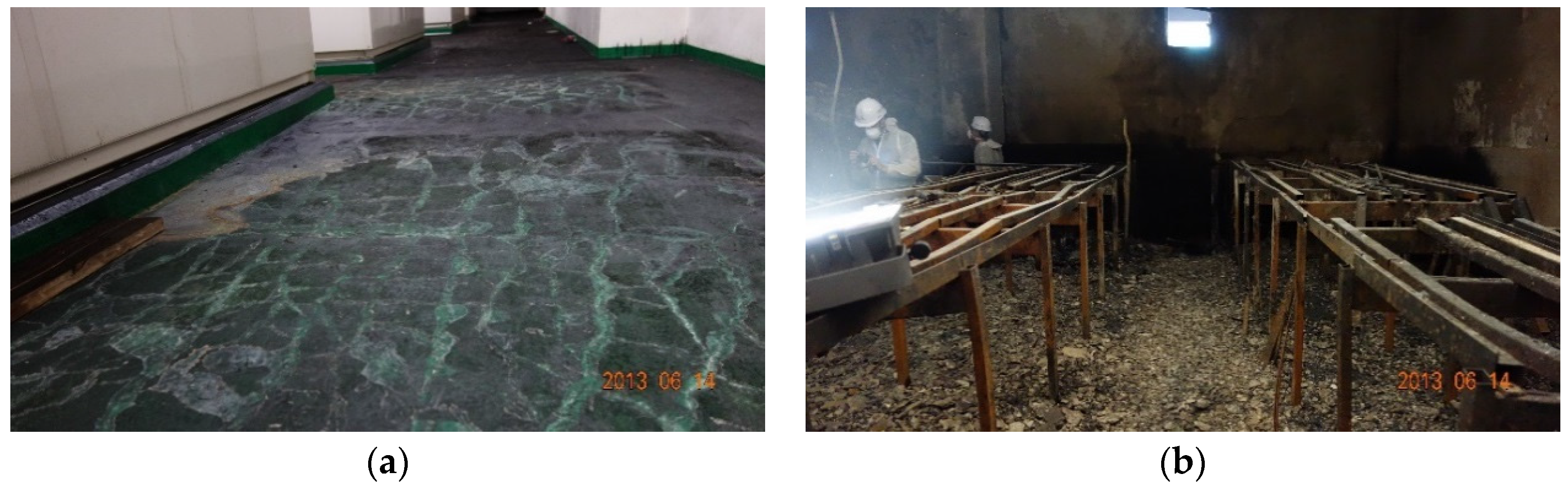
Figure 4a shows the floor conditions of the HVAC (Heating, Ventilation and Air Conditioning) room, which is located right above the battery room where the fire occurred. It indicates that, in the area where the concrete has spalled, a network of cracks has developed on the top surface of the floor slab. At the time of the visual inspection, the damage to the floor slab of the battery room was not identifiable, since the debris on the floor had not been removed (see
Figure 4b). Inferring from the fact that the steel structures supporting the batteries remain without excessive deformation, it is assumed that there was little or no structural damage to the floor slab.
Having lost more than half of the concrete volume, all the spans from Slabs #1 to #4 are judged to have degradation in their structural capacity. The main role of the slab is to transfer the transverse load on the slab to adjacent girders and beams. This role must be restored by either replacing the damaged span of slab with new ones or by providing additional load carrying capacity to the slab. The exposed reinforcing bars might have experienced a strength reduction due to the elevated temperature during the fire. To identify the degree of the strength reduction, tests on the rebar specimens from the respective spans of slab were necessary. Although not identifiable at the time of inspection, the floor slab of the room was assumed to have retained its structural capacity and needed no retrofitting.
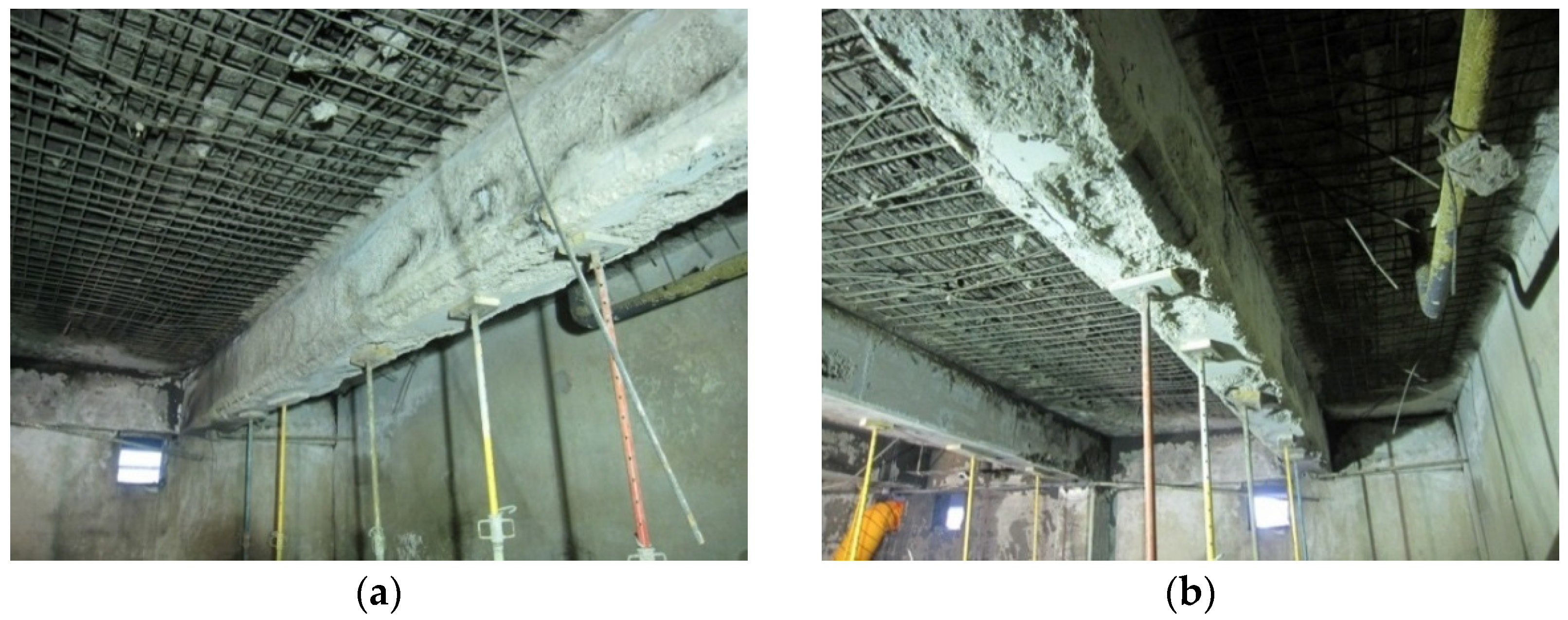
The degree of damage in the girders and beams varied by component. At some points, the concrete covers at the bottom corner and side of girders and beams spalled and, although not dominant, the longitudinal bars and stirrups were exposed. However, neither a structural crack in vertical and diagonal nor a deflection at the center of girders and beams was identified with the naked eye. As shown in
Figure 5,
Figure 6,
Figure 7 and
Figure 8, the condition of the girders and beams can be summarized as follows:
Girder #1: One longitudinal rebar at the bottom corner was exposed by 1–2 m, and 7 stirrups were exposed due to the spalling of concrete both at side cover and inside the stirrups.
Girder #2: No marked exposure of the longitudinal rebar was observed. Concrete spalled on the side of Slab #3 at a slight depth. Two stirrups were partly exposed toward the end of the span at the location of Column #3.
Girder #3 to #6: These girders comprise the longitudinal edge of the room. No marked damage was observed on these girders except that a longitudinal bar at the corner of Girder #6 was exposed by 3 m.
Beam #1: Longitudinal rebar was exposed at each corner by about 4 m. Sides of the beam are not deemed to have been affected by fire.
Beam #2: Extensive spalling of the concrete cover both at bottom and sides was observed. Longitudinal rebar was exposed at the corners, and stirrups were slightly visible at some areas.
In spite of the spalling of the concrete cover and the exposure of reinforcing bars, the girders and beams were deemed to still retain their designed structural capacity, judging from the fact that neither flexural cracks at mid-span nor diagonal cracks toward the span-ends were found, and deflection at the center of the element was not detected with the naked eye. However, a possible degradation in the load-carrying capacity must be retrofitted by testing the strength of the damaged concrete and the exposed reinforcing bars, and then by providing the required amount of reinforcement to compensate for the degraded capacity.
In the battery room, there are four columns and six non-bearing walls made of blocks. None of the columns showed signs of damage in the visual inspection. The walls showed no signs of cracks on their surfaces except for the spalling of plasters and paint on the surface of Walls #1 and #3, and the extensive contamination of the surface due to smoke from the fire. No specific damage was observed on four columns, i.e., no sign of cracks, spalling of the concrete, or exposure of the reinforcing bar. Therefore, no special action is necessary to restore their structural capacity.
3. Material Tests
In order to supplement the results of the visual inspection discussed in the previous section, both an indicator test and a strength test were performed. This section summarizes and discusses the results of these tests.
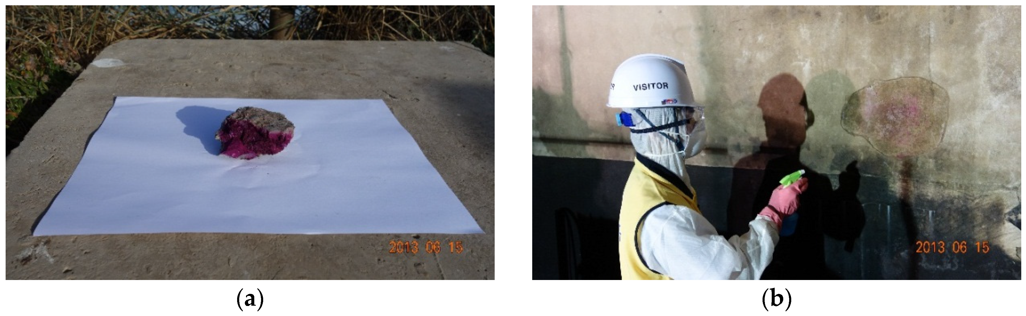
3.1. Neutralization Test of Concrete
To determine the degree of neutralization of the concrete by its pH level, the phenolphthalein (C20H14O4) indicator method was adopted. The key indicator of this test is that a solution of Phenolphthalein remains colorless in acids or neutral liquids, but turns bright reddish/pink in alkalis. Therefore, it is possible to infer the temperature history and neutralization depth through the change of color in the test surface of concrete, which permits the soundness and the reusability of the concrete exposed to fire to be judged.
For the normal condition of concrete, calcium hydroxide, Ca(OH)
2, is created in the hydration process of cement, which is described by
Calcium hydroxide is a strongly alkaline product with a pH value ranging from 12 to 13. One of the particular characteristic of calcium hydroxide is that it decomposes into calcium oxide (CaO) and water by chemical decomposition at elevated temperatures (above 500 °C), such as those in a fire environment. As a result, the concrete gets neutralized, which is described by
The test was first performed on a sample piece of concrete popped out from the slab and on a part of wall where the plaster had already spalled, respectively, and then on small part of Girder #1 and Beam #2, both on the surface and inside the side cover. Both the piece of concrete and the part of the wall changed color almost instantaneously when the phenolphthalein indicator was applied as shown in
Figure 9.
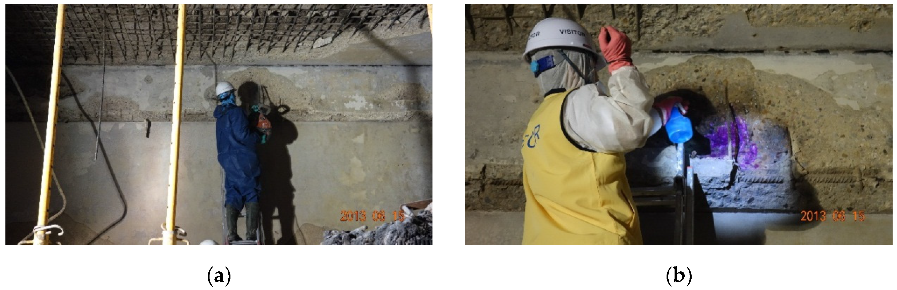
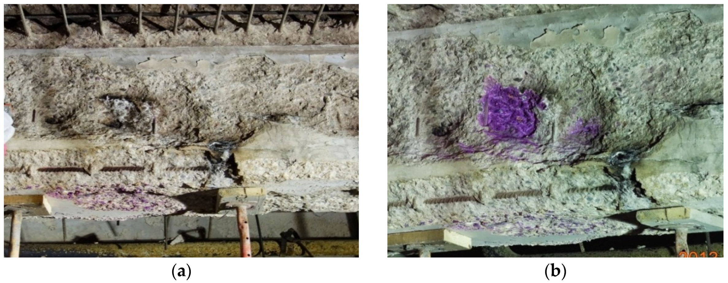
During the test on the girder and the beam, 1% phenolphthalein solution was first applied to their side surfaces that were affected by the fire without treating the surfaces. As shown in
Figure 10a, the color did not change in most of the region, with a purple area where the alkaline concrete reacted to the indicator. When the indicator was applied after chipping out the surface of concrete by 10 mm, a significant change in the color was immediately observed as shown in
Figure 10b and
Figure 11. Therefore, the girder and beam are judged not to have experienced a maximum temperature of more than 500 °C and, as a result, have remained sound. We infer that the concrete in the girders and beams spalled during the fire not due to the degradation of the concrete itself, but to the sudden increase in temperature at the upper level in the room. The elevated temperature is deemed to have caused the expansion of the aggregate inside the concrete and to have weakened the so-called transition zone between the aggregate and the cement matrix.
3.2. Strength Tests
Two types of strength tests were performed on the concrete cylinders and rebar coupons. The purpose of the tests is to evaluate the remaining capacity of the structural element and, consequently, to determine the degree of retrofit required to recover the original structural capacity.
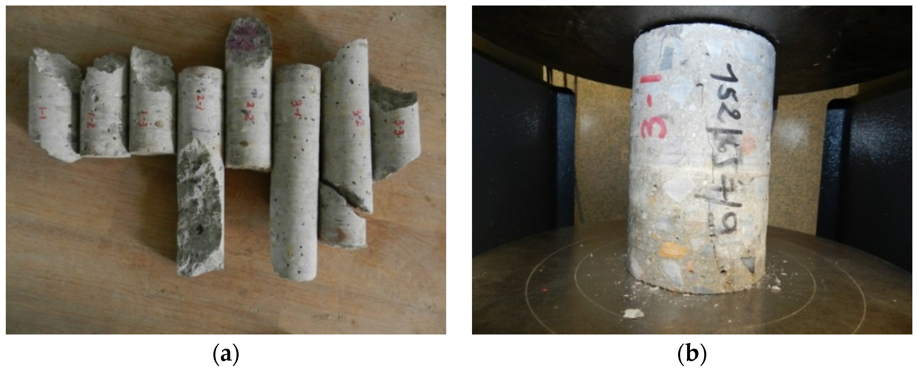
For the strength test of the concrete cylinders, two or three cylinders with diameters of 100 mm were sampled from Beams #1 and #2, and Girder #2 indicated in
Figure 12, respectively. Examples of the cored specimens are shown in
Figure 13. The compressive strength tests of these specimens were conducted per ASTM (American Society for Testing and Materials) C42 [
11]. The results are summarized in
Table 1. Excluding the test results from three non-confirmative specimens represented by the shaded region, which are 1-1, 3-2 and 3-3, the average compressive strength was 30.7 MPa. This is equivalent to the design compressive strength (
fc’), 30 MPa. According to BS EN 13791 [
12,
13,
14], the strength of cored specimens is lower than that of molded specimens due to the micro-cracks developed by the impact from drilling during the sampling process. The minimum characteristic
in-situ compressive strength required by BS EN 13791 is calculated by multiplying a factor of 0.85 and the design strength.
ACI 318-05 [
15,
16] also provides a guideline for evaluating the original strength based on the core test in Section 5.6.5.4: Concrete in an area represented by core tests shall be considered structurally adequate if the average of three cores is equal to at least 85% of
fc’ and if no single core is less than 75% of
fc’. Since the average compressive strength of the core specimens is greater than 85% of the design strength,
i.e., 25.5 MPa, and none of the test results are below 75% of the design strength,
i.e., 22.5 MPa, the damaged girders and beams are judged to have remained sound in terms of concrete strength.
Three rebar coupons 600 mm in length were sampled from each span of slab and also from one of the damaged girders, Girder #1. Their yield strength, tensile strength, and elongation were obtained as
Table 2 according to ASTM E8-09 [
17]. As shown in the table, the yield and tensile strengths of the longitudinal rebar in Girder #1 are much higher than the designed yield strength of 400 MPa. The yield strength of the stirrup is slightly below the design strength but almost reached the level that would not degrade the shear strength of the girder. In the case of the reinforcing bars obtained from the slabs, the measured strengths are on the level of 60%–70% of the original strength, except for the Slab #2 where the fire was first extinguished. The specimen φ14-2 showed sufficient strength levels, but the degree of elongation was relatively smaller than other rebar coupons.
The results of the tests discussed in this section show that the compressive strength of concrete cores and the yield strength of longitudinal rebar were above the design strength, and the yield strength of the stirrups was slightly below the design strength. Only the residual strength of reinforcing bars obtained from the slab generally degraded from their original capacity.
4. Numerical Analysis
This section discusses the results of the finite element analysis on a typical sample girder and two typical columns in the Battery Room #6 performed to investigate their remaining structural capacity. As target structural components, Girder #2 and Columns #3 and #4 were selected. (Refer to
Figure 1 for identification of these members.) Girder #2 was chosen because it transfers the load from adjoining slabs directly to the columns. As illustrated in
Figure 14, different damaged models were considered for the two target columns as they have different shapes of exposure to fire,
i.e., a shape of channel for Column #3 and a shape of angle for Column #4. The following assumptions are made in the course of modeling. They are based on the results of the on-site inspection and tests on the sampled core cylinders (see
Table 1) and rebar coupons (see
Table 2):
- (i)
Rebar is undamaged;
- (ii)
The depth of damaged concrete is about 50 mm as shown in
Figure 14;
- (iii)
The residual strength of the damaged concrete is approximately 60% compared with the original capacity.
A material and geometric nonlinear finite element analysis was conducted on the target structural components using Abaqus/Standard v6.12 [
18] (Dassault Systemes Simulia Corp., Providence, RI, USA, 2012), which is a well-known commercial finite element analysis package. As a concrete material model, the so-called “concrete damaged plasticity model” was used. In this model, the behavior of concrete under compression is defined by Mander’s model, which is discussed in [
19], while its behavior under tension is defined by a bi-linear tension softening curve with a peak strength corresponding to 10% of its compressive strength. The compressive strength, elastic modulus and Poisson’s ratio of concrete are 30 MPa, 52.4 GPa and 0.15, respectively. For rebar, a bi-linear stress-strain relationship was applied without considering strain hardening to conservatively evaluate the remaining capacity of the fire-damaged structural components. Their tensile yield strength and elastic modulus are 500 MPa and 206,000 MPa, respectively.
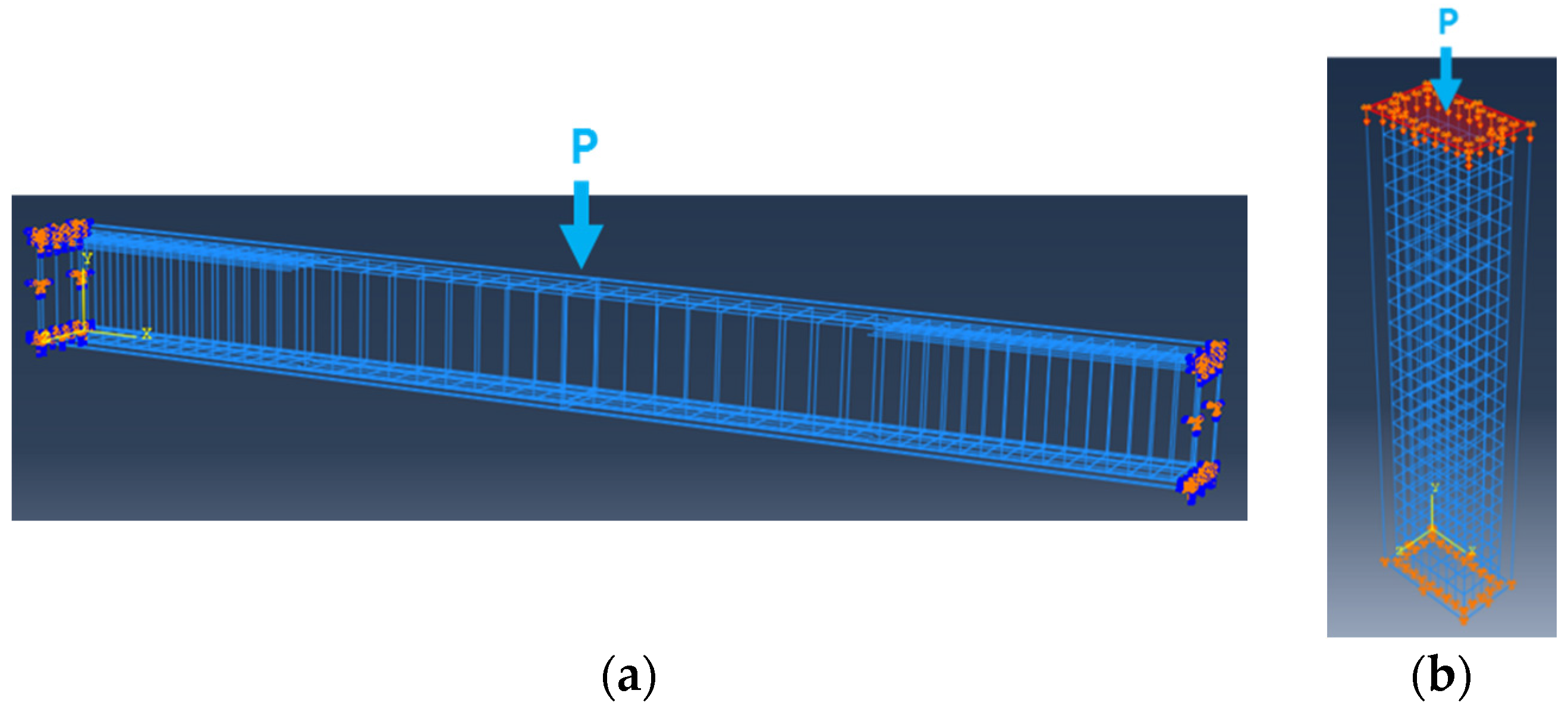
Figure 15 shows the numerical models of the target structural components including rebar arrangement. The target concrete girders and columns were modeled using 8-node solid elements with reduced integration (C3D8R). The rebar was modeled using truss elements (T3D2) with the embedded option in ABAQUS. Both edges of the target components were restrained to simulate axial and rotational restraint effects provided by the adjacent structural components, which reflects the actual condition of girder and column connections. A displacement-control analysis was conducted by imposing a vertical displacement in the middle of the beam and on the top surface of the column, respectively, as illustrated in the figure. The numerical modeling adopted in this study is also utilized in [
20,
21], thus confirming its validity.
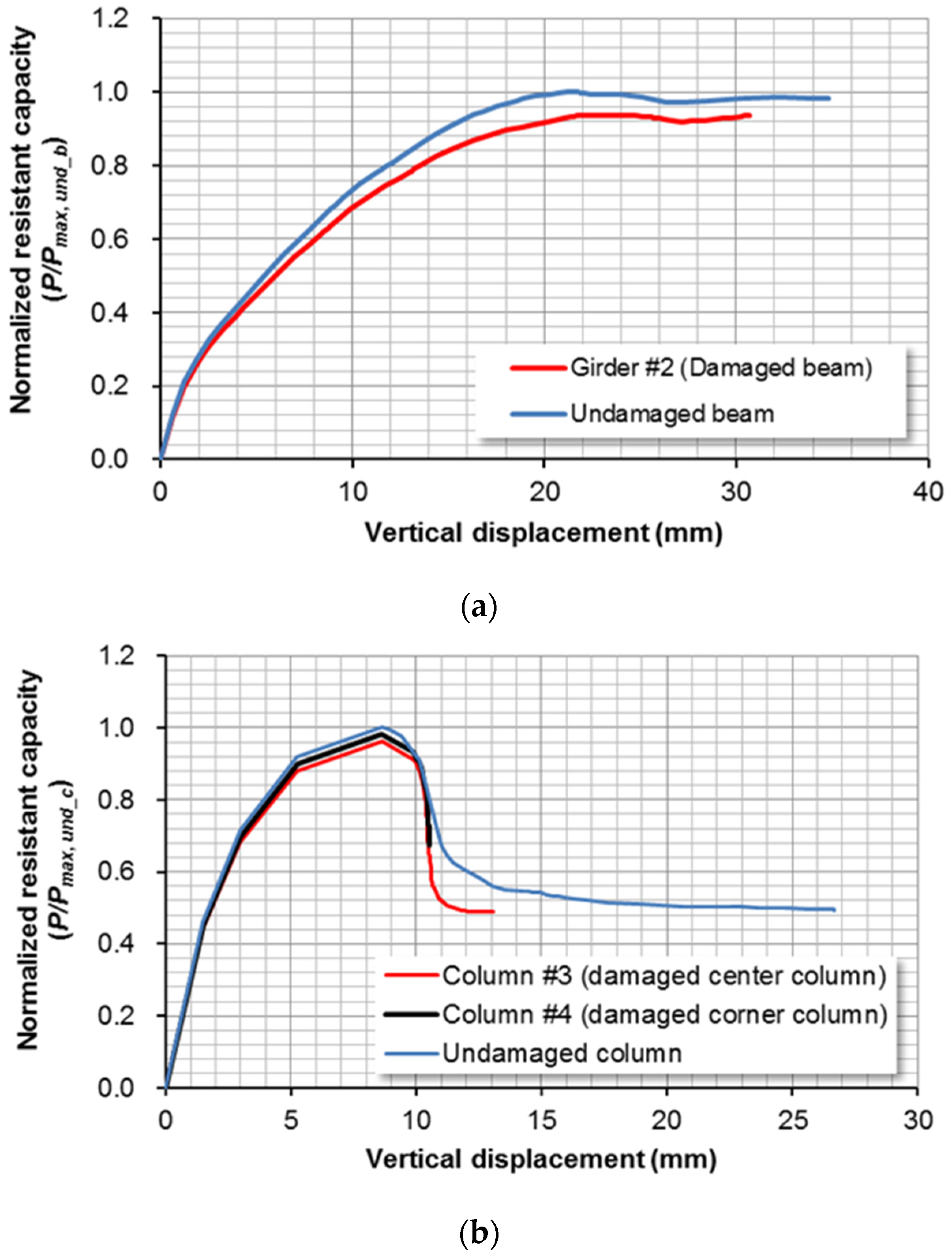
Figure 16a,b shows the load-displacement curves obtained from the numerical analysis for Girder #2 and Columns #3 and #4, respectively. The load-displacement curves of undamaged (
i.e., original) components are also provided in the figures. In these figures, the ordinate axis indicates the vertical load normalized by the peak load value of the undamaged structural component.
Table 3 summarizes the results of the numerical analysis. In the table,
Pmax, und_b and
Pmax, und_c indicate the vertical resistant capacities of the undamaged beam and column, respectively.
It can be seen from the results of the table that the maximum vertical load (Pmax) of Girder #2 is approximately 94% of the corresponding value of the undamaged member. In structural engineering practice, the design strength of the girder is generally 90% of its demand strength. In addition, the vertical displacement values corresponding to Pmax of the damaged and undamaged girders are almost the same, which indicates that they have almost the same ductility capacity. Consequently, it can be concluded that Girder #2 still has enough resistant capacity.
Similar to the case of Girder #2, Pmax’s of Columns #3 and #4 are approximately 96% and 98% of the corresponding value of the undamaged column, respectively. The vertical displacements corresponding to Pmax are the same in all of the damaged and undamaged cases. As a consequence, it can be also judged that Columns #3 and #4 still have enough resistant capacity.
From this discussion, overall it can be observed that the behavior pattern and the maximum vertical load are hardly affected by the components that are assumed to be damaged. In other words, in spite of the loss of the sectional area and material strength of the target structural components, since the core concrete surrounded by stirrups, ties and rebar survived the fire hazard, it can be concluded that all of the target damaged girder and columns retain enough strength.
5. Rehabilitation Plan
Based on the results of the visual inspection, material tests, and finite element analysis discussed in the previous sections, the remaining structure needs to be rehabilitated. The scope of the rehabilitation can be summarized as follows:
Operation floor structure (slabs, girders and beams): severe or partial damage to the concrete and reinforcing bars, thus retrofit is required.
Columns and walls: damage to the surface or plastering only, thus finishing work is required without structural retrofit.
Mezzanine floor structure: damage cannot be identified but no marked damage is inferred, thus inspection is required after removing the debris on the floor.
The retrofit methods of the damaged girders and beams can be summarized as:
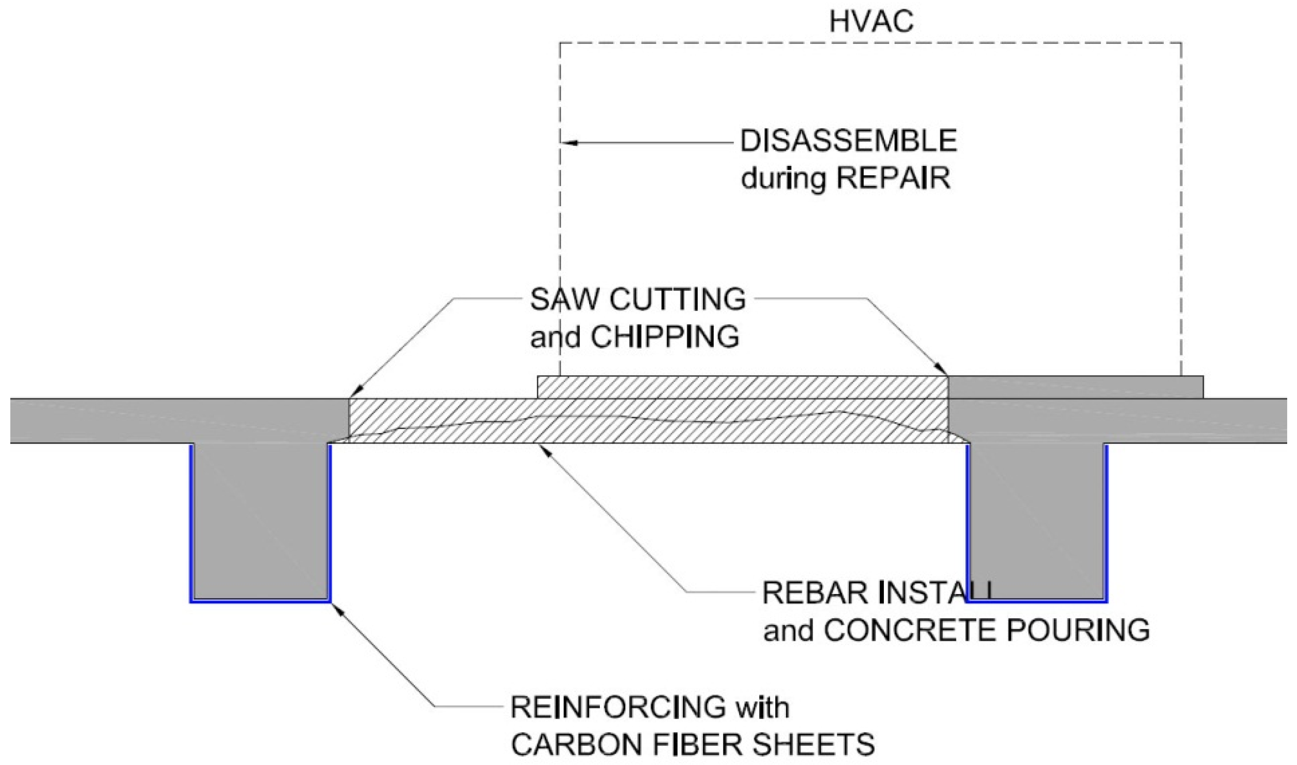
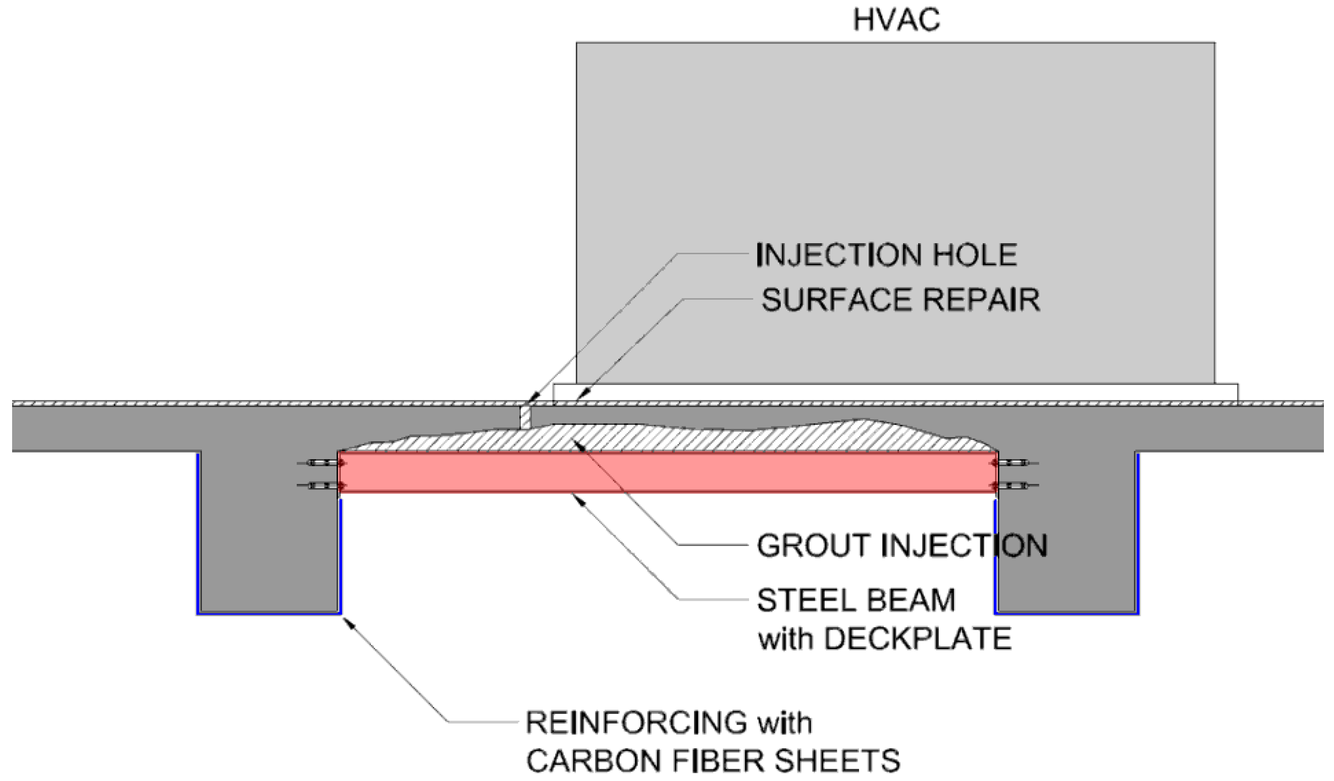
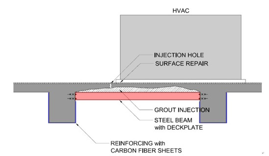
Regarding the retrofit methods of the damaged slabs, there are two options depending on the handling method of the HVAC system located right above the battery room. The differences between the two options are analyzed in
Table 4. They are also illustrated in
Figure 17 and
Figure 18, respectively.
6. Concluding Remarks
This paper presents a case study on establishing a rehabilitation plan for a fire-damaged reinforced concrete structure. A team of structural and material researchers/engineers in concrete inspected the structure in the earliest possible time after the fire, and carried out both on-site and laboratory tests on the damaged concrete and rebar. A finite element analysis was also performed to estimate the residual capacity of the structure. The following is the conclusion of the study and the recommended rehabilitation methods.
(1) Through visual inspection of the structure, the mostly damaged structural elements were identified as the slabs, the girders and beams being the second, and the columns, wall, and the floor slab were the least affected elements. The slabs were mostly damaged because they are located at the highest elevation of the room where they are exposed to the highest temperature during the fire.
(2) The judgment from the visual inspection is supported by the material test using the indicator method, where the concrete beneath the surface proved to retain its alkaline property for the girders, beams, walls, and even for the slabs.
(3) Strength tests on concrete cores and rebar coupons obtained from the slabs, girders and beams showed that the concrete and the reinforcing bars in the girders and beams were only slightly damaged and still fit for continuous usage, while the reinforcing bars in the slab had considerably degraded in their structural capacity and therefore could not be used any longer.
(4) A finite element analysis was also performed assuming more severe condition, i.e., the strength of concrete structure in both the girders and columns amounting 50 mm from the cover degraded to the level of 60% compared with the original strength. The results of analysis also confirmed that the girders and columns remain strong and stiff enough to perform their original structural intent.
(5) It is recommended that the slabs be replaced with new ones, and the girders and beams be retrofitted. The columns and walls only needs surface treatment without a structural retrofit.
(6) Considering the tight construction schedule and complexity of rehabilitating work, including the dismantling and reassembly of HVAC system in upper floors, a more efficient method of work is proposed as an alternative plan: a series of steel beams and deck plates perform the role of temporary slabs during the rehabilitation work and act as permanent supplementary slab when the rehabilitation work is over.


