Article

A Novel Ropes-Driven Wideband Piezoelectric Vibration Energy Harvester

1
Department of Mechanical and Electrical Engineering, Xiamen University, Xiamen 361005, China
2
Department of Mechanical Engineering, New York Institute of Technology, Old Westbury, NY 11568, USA
*
Authors to whom correspondence should be addressed.
Appl. Sci. 2016, 6(12), 402; https://doi.org/10.3390/app6120402
Submission received: 13 October 2016 / Revised: 18 November 2016 / Accepted: 28 November 2016 / Published: 2 December 2016
(This article belongs to the Section Energy Science and Technology)

Abstract

:
This paper presents a novel piezoelectric vibration energy harvester (PVEH) in which a high-frequency generating beam (HFGB) is driven by an array of low-frequency driving beams (LFDBs) using ropes. Two mechanisms based on frequency upconversion and multimodal harvesting work together to broaden the frequency bandwidth of the proposed vibration energy harvester (VEH). The experimental results show that the output power of generating beam (GB) remains unchanged with the increasing number of driving beams (DBs), compared with the traditional arrays of beams vibration energy harvester (AB-VEH), and the output power and bandwidth behavior can be adjusted by parameters such as acceleration, rope margin, and stiffness of LFDBs, which shows the potential to achieve unlimited wideband vibration energy-harvesting for a variable environment.

1. Introduction

Energy harvesting from ambient vibration—such as industrial machines, human activity, vehicles, structures, and environment sources—offers a clean, regenerative means for powering small-scale systems [1,2]. The vibration energy can be transformed into electrical power through three main mechanisms including piezoelectric, electromagnetic, and electrostatic. Since piezoelectric material can effectively convert mechanical vibration into electrical energy using a very simple structure, the piezoelectric energy-harvesting technique is highlighted as a self-powered source for wireless sensor network systems [3]. Typical piezoelectric vibration energy harvesters (VEHs) are composed of a mass-spring-damper system with a transducer based on linear mechanical principles [4]. Such devices give an appreciable response amplitude only if the dominant ambient vibration frequency is close to the resonant frequency of the harvester [5], and the output drops dramatically when ambient vibration frequency is slightly different from the resonant frequency. Hence, it is impractical for the VEH, which is designed based on one resonant frequency mode with narrow bandwidth, to harvest energy from a variable environment.
In order to overcome this gain bandwidth dilemma, researchers have paid attention to different approaches on broadening the operation bandwidth of vibration energy harvesters, which can be simply classified into the nonlinear harvesting technique and the multimodal harvesting technique [6,7]. In the case of the nonlinear harvesting technique, usually extra magnetic force or mechanical force is purposely introduced as a nonlinear restoring force to control the magnitude and property of the nonlinearity in the system, thus enhancing transduction of the energy harvester under broadband excitations can be achieved [8,9,10,11,12,13,14,15,16,17,18], while the bandwidth is still limited. In the case of the multimodal harvesting technique, it is mainly based on the structure of beam arrays, which have different frequencies to match the wideband excitation's components, can be classified into unconnected mechanical structure systems [19,20,21,22,23]—connected mechanical structure systems using springs [24,25]—and multi-resonance systems [26,27,28,29,30,31]. Compared with a conventional single piezoelectric beam EH, much higher bandwidth of the EH can be realized by the multimodal harvesting technique. Moreover, wider or even unlimited bandwidth can theoretically be achieved with a greater number of beams added; however, output power will dramatically decrease with the number of beams, making it impractical for real applications, and this phenomenon is obviously worse for VEHs of a small size.
In this paper, we propose a novel wideband piezoelectric vibration energy harvester (PVEH), in which a high-frequency generating beam (HFGB) is driven by an array of low-frequency driving beams (LFDBs) using ropes. We take advantages of frequency upconversion and multimodal harvesting technique mechanisms, which not only can produce unchanged output power with the increasing number of beams, but also has the potential to achieve unlimitedly wideband energy harvesting. Meanwhile, the characteristics of each LFDB driving HFGB is affected by multiple parameters, thus, for practical applications, the output and bandwidth can be optimized by changing these parameters, such as acceleration, rope margin, and stiffness of LFDBs. This wideband operation of the device offers a promising approach to work effectively in very complicated environments.

2. Working Principle

2.1. Frequency Upconversion and Multimodal Mechanisms

As shown in Figure 1a, the proposed wideband PVEH system is composed of one high-frequency beam attached with piezoelectric material as the generating beam (GB) and multiple low-frequency beams as driving beams (DBs) having different frequencies arranged face-to-face with a predetermined space, and multiple DBs are connected mechanically with the GB using ropes. For the structure of an individual DB driving the GB, the architecture and schematic model are shown in Figure 1b,c. The equivalent schematic model contains (1) an excitation oscillator as the DB with stiffness k0, damping coefficient c0, and proof mass m0; (2) another oscillator as the GB, which acts as a generator oscillator, is placed at a distance of x0 above the excitation oscillator, with higher stiffness k1 than k0, damping coefficient c1, and proof mass m1; and (3) the rope with stiffness k2, which is used to connect the excitation oscillator and generator oscillator with a length of x1. The operation mechanism is depicted in Figure 1d. When the LFDB is excited with sufficiently large amplitude that exceeds the rope margin Δx (defined as length of rope x1 minus x0), the LFDB pulls the HFGB by the rope and vibrates together with the HFGB for a short period. After this period, the HFGB gets mechanical energy from LFDB by the rope and oscillates with exponentially attenuating amplitude at its higher resonant frequency, and the cyclic deformation of piezoelectric layer on HFGB will be transformed into electricity due to the piezoelectric effect. The operating principle of LFDB driving HFGB to output energy by HFGB can be treated as a frequency upconversion mechanism, which can well-realize wideband energy-harvesting and improve output power efficiency for low-frequency applications [12,13,14,15,16,17,18].
Based on the equivalent schematic model and operating mechanism of the proposed VEH system, as shown in Figure 1c,d, the differential equations of the motion can be written as
{ ( m 0 + m 1 ) z ¨ + ( c 0 + c 1 ) z ˙ + ( k 0 + k 1 + k 2 ) z ( k 1 + k 2 )   Δ x = ( m 0 + m 1 ) y ¨ ( z Δ x ) m 0 z ¨ + c 0 z ˙ + k 0 z = m 0 y ¨ ( z < Δ x )
The operating mechanism and equivalent schematic model of individual rope-driven frequency-upconverted EHs are similar to the impact-driven frequency-upconverted EHs using a stopper, which has been analyzed and demonstrated in the literatures [13,14,15,16,17,18,32]. Hence, similar derivations can be used in this novel EH model. Here, assuming that the stiffness k2 of rope is far smaller than the stiffness k0 and k1, and the proof mass of m0 is far bigger than the mass of m1, Equation (1) can be rearranged as follows:
{ m z ¨ + ( 2 ξ 0 ω 0 + 2 ξ 1 ω 1 ) z ˙ + ( ω 0 2 + ω 1 2 ) z ω 1 2 Δ x = m y ¨ ( z Δ x ) m z ¨ + 2 ξ 0 ω 0 z ˙ + ω 0 2 z = m y ¨ ( z < Δ x )
where y(t) = Ysin(ωt) is a harmonic base excitation, Y is the amplitude of the base excitation, z(t) is the displacement of LFDB relative to the base, ξ0 and ω0 are the LFDB damping and frequency characteristics, and ξ1 and ω1 are the HFGB damping and frequency characteristics, which are defined as 2ξ0ω0 = c0/m0, 2ξ1ω1 = c1/m1, ω02 = k0/m0, and ω12 = k1/m1. Thus, the amplitude of the LFDB displacement against excitation frequency ω can be obtained numerically based on Equations (3) and (4).
Z 1 = 2 a ξ 0 π ω ω 0 a ξ 1 ( π 2 φ s i n 2 φ ) ω ω 1 ω 0 2
Z 2 = π a ( 1 ω 2 ω 0 2 ) [ 1 2 a ω 1 2 ω 0 2 ( 2 φ s i n 2 φ π ) + 2 ω 1 2 Δ x ω 0 2 Y c o s φ ]
where φ = sin−1x/aY) is the phase angle when the LFDB pulls the HFGB, and a is the dimensionless amplitude with respect to frequency ω/ω0. Detailed derivations can be found in the literatures [17,32]. The instantaneous output voltage of HFGB with optimal impedance as a function of time t can be expressed by [14,15]
V ( t ) = { V O C 2 s i n ( ω c t ) e ξ t 0 ω c t , 2 n π / ω < t < 3 ( n + 1 ) π / 2 ω c , p h a s e 1 V O C 2 s i n ( ω 1 ( t 3 ( n + 1 ) π / 2 ω c ) + 3 π 2 ) e ξ t 1 ω 1 t , 3 ( n + 1 ) π / 2 ω c t ( n + 1 ) π / 2 ω , p h a s e 2
where phase 1 is the coupled vibration of LFDB and HFGB, phase 2 is the separation vibration of HFGB, n = 0, 1, 2, 3, ...... is the number of the harvester’s cycle, ξt0 and ξt1 are the total damping ratio of the coupled vibration and the HFGB respectively, ωc is the frequency of the coupled vibration (which can be calculated based on the assumption that the LFDB and the HFGB connected with rope never separate after pulling, and then given by ω c = ( k 0 + k 1 ) / m , and Voc is the maximum open voltage generated by HFGB.
It needs to be pointed out that, for the proposed VEH system, when an individual DB pulls the GB to realize wideband energy harvesting, the working principle is similar to the impact-driven frequency upconverting wideband VEH using a stopper [13,14,15,16,17,18,32]. However, unlike the bandwidth of impact-driven VEHs that get wider but are still limited [17,18,32], the novel VEH system uses the rope to replace the direct mechanical collision and can easily realize wider or even unlimited bandwidth just by increasing the number of LFDBs, using the ropes to transfer the energy from multiple LFDBs to HFGB. Therefore, appropriately setting the number and resonant frequencies of LFDBs can achieve unlimited bandwidth to match a variable environment, which is named “multimodal harvesting mechanism”.
Based on the structure of HFGB driven by multiple LFDBs together, the proposed VEH is based on frequency upconversion and multimodal mechanisms to achieve a superiorly wide bandwidth. Obviously, the novel ropes-driven wideband energy harvester offers two advantages. Firstly, it has the potential to achieve wider or even unlimited bandwidth by adding LFDBs connected with ropes. Secondly, the output power will not be weakened with the increasing number of LFDBs, unlike arrays of beams vibration energy harvester (AB-VEH) for wider bandwidth [19,20,21,22,23], and the reason in shown below.

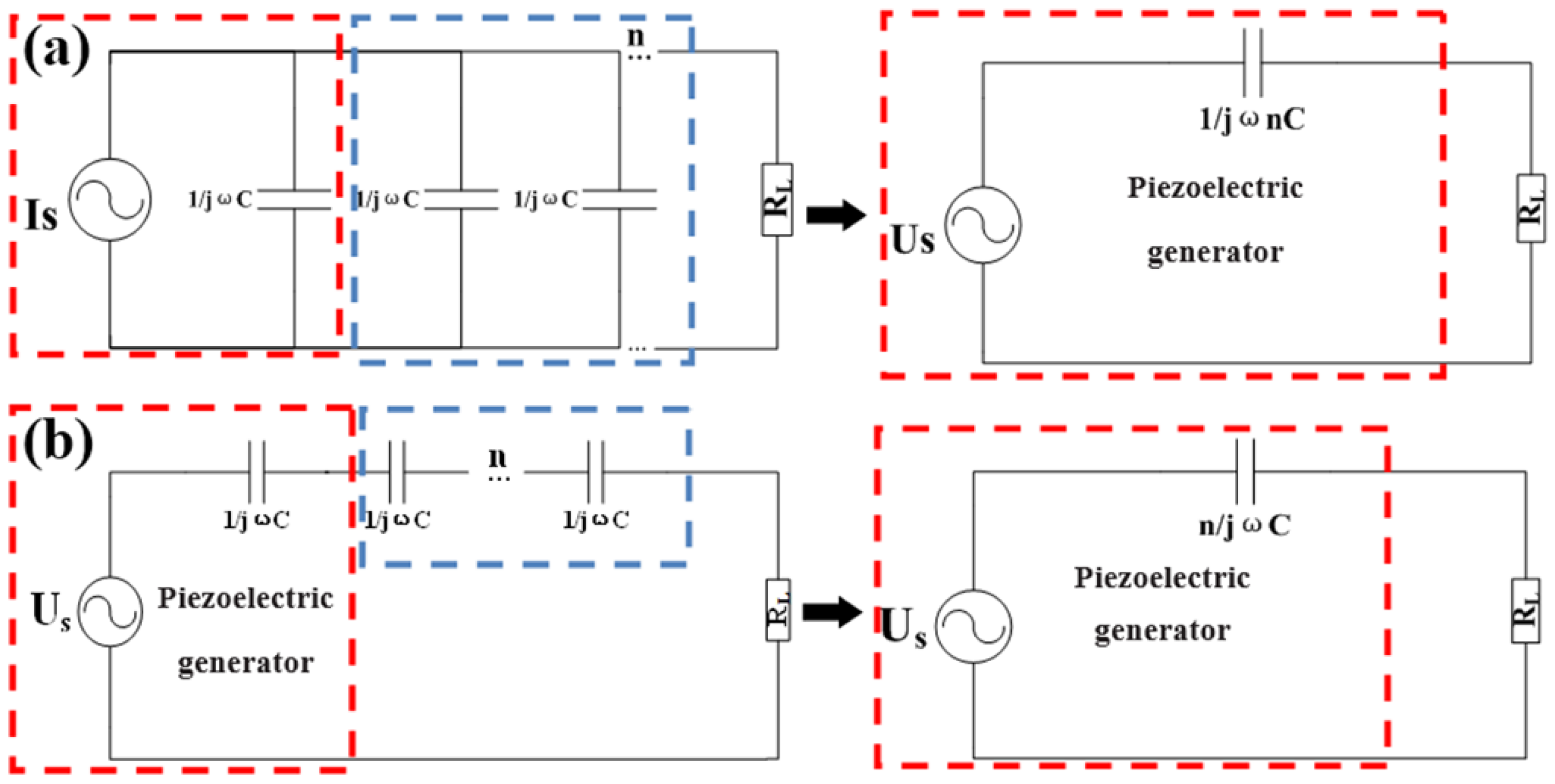
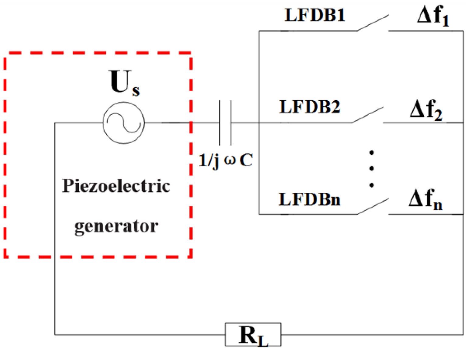
2.2. Unlimited Bandwidth with Unchanged Output

For the traditional AB-VEH, which is composed of multiple beams attached with piezoelectric material as generators, the equivalent circuit model connected in parallel and in series are shown in Figure 2a,b respectively. For convenience of discussion, when ambient vibration frequency is closed to the operation frequency of one generating beam, only this beam works effectively while the others hardly work, which can be regarded as a capacitor with the same value of Cp. Therefore, the equivalent circuit can be simplified to a voltage source U ˙ S , and an equivalent impedance 1/jnωCp in parallel or n/jωCp in series (n = 1, 2, 3, ……), then the maximum output power PLmax delivered to load resistance RL can be determined by
P L max = | I ˙ S ( | 1 / j n ω C p | ) 2 + R L 2 | 2 × R L =   I S 2 2 n ω C p ,   R L = R m = 1 n ω C p
P L max = | U ˙ S ( | n / j ω C p | ) 2 + R L 2 | 2 × R L = I S 2 2 n ω C p ,   R L = R m = n ω C p
where Equations (6) and (7) are the maximum output power in parallel and in series, respectively, ω is vibration frequency, and Rm is optimal load resistance for maximum output power. As seen from Equations (6) and (7), the maximum output power is inversely proportional to the number of beams arrayed in either a parallel or series connection. Obviously, it is not practical to realize unlimited wideband energy-harvesting for real applications.
The equivalent circuit model of the proposed ropes-driven wideband VEH is illustrated in Figure 3. Different from AB-VEH, the novel device only has one generating beam. Here, assuming each LFDB works individually for convenience of discussion, when one LFDBi (i = 1, 2, 3, ..., n) drives HFGB to oscillate during its own operation frequency Δfi, the switch corresponding to LFDBi is closed and others are still opened. Thus, if the closed circuit is composed of an equivalent voltage source U ˙ S , impedance 1/jωCp, and load resistance RL, the maximum output power PLmax of RL can be given by
P L max = | U ˙ S ( | 1 / j ω C p | ) 2 + R L 2 | 2 × R L =   U S 2 2 / ω C p = I S 2 2 ω C p ,   R L = R m = 1 ω C p
where U ˙ S and 1/jωCp are the equivalent voltage source and internal impedance of HFGB, and ω is the resonant frequency of HFGB during the oscillation. Equation (8) illustrates that the maximum output power is irrelevant to the number of LFDBs. Hence, the novel device can achieve wider or even unlimited bandwidth without sacrificing output power.

2.3. Adjustable Performance

Since the wideband mechanism of the individual LFDB driving an HFGB VEH using rope is similar to the wideband VEH using a stopper, the analytical model of the wideband VEH using a stopper, which has been built and analyzed by Soliman et al. [12] and Liu et al. [17,18], is applicable to our proposed VEH system. Based on the analytical model, it is found that the key parameters affecting the output and wideband behaviors include input acceleration, effective stiffness of LFDBs, and rope margin. According to our experimental results, for multiple LFDBs driving an HFGB together at a fixed acceleration, a better performance (wider operating bandwidth with continuous output) can be realized by adjusting parameters such as rope margin and stiffness of LFDBs.

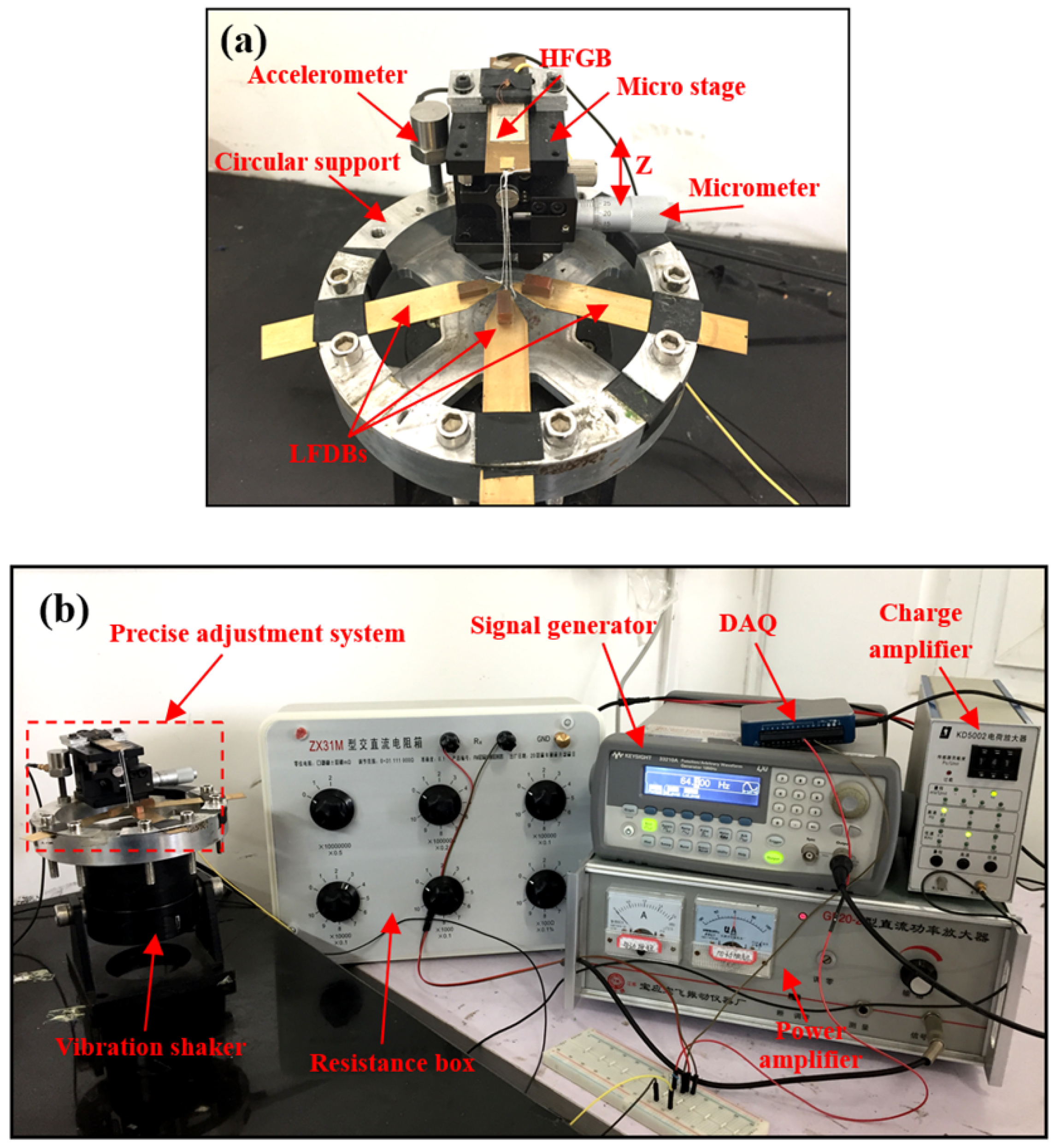
3. Device Configuration and Experimental Setup

A vertical view of the experimental system is illustrated in Figure 4. As shown in Figure 4a, AB-VEH is composed of a three-beam array with piezoelectric material, PZT (Sinoceramics, Ins., Shanghai, China). The beams array comprises a brass supporting base attached with a PZT (5 mm × 14 mm × 0.15 mm) layer and copper proof mass attached to the top of beams. The resonant frequencies of these three beams are 58.8, 64.4, and 69.8 Hz, respectively, and the detailed geometry is shown in Table 1. In addition, the three piezoelectric beams of the array have the same optimal load resistance of 250 kΩ, and are connected in parallel and series to measure the maximum output power with optimal load resistance. The characteristics of output power are compared with the proposed VEH system to verify the novel system’s superior output performance with the increasing number of beams.
The novel VEH system has a configuration similar to the AB-VEH system, but the novel VEH system is composed of one HFGB, besides three brass beams array as LFDBs, as shown in Figure 4b. The HFGB comprises a brass supporting base (39.2 mm × 14 mm × 0.5 mm) attached with a PZT layer (20 mm × 14 mm × 0.15 mm) without inertial mass, and the resonant frequency is 206.8 Hz. Three LFDBs have similar dimensions and configuration with that of the beams array of the AB-VEH system, but without a piezoelectric layer, and the resonant frequencies are 64.4, 69.8, and 75.6 Hz, respectively, and the detailed geometry is shown in Table 1. Meanwhile, the dacron-ropes are used to connect the HFGB with LFDBs with the same predetermined rope margins of 0.8 mm. When the vibration amplitude of LFDBs is larger than the rope margin, the HFGB is triggered by the ropes into a high-frequency self-oscillation, and the electric current is generated once the PZT layer on HFGB deforms. The characteristic of output power is measured under optimal load resistance with the increasing number of LFDBs.
Figure 5 shows the detail experimental setup of the novel PVEH system. To experimentally study the output power, wide bandwidth, and adjustable performance of the novel PVEH system, a precise adjustment system was used to finely adjust the rope margins between the HFGB and LFGB. As shown in Figure 5a, the precise adjustment system comprises a micro-stage, a micrometer, and a circular support. The HFGB is fixed on the micro-stage and then fixed to the circular support, the LFDBs array is fixed on the support directly under the HFGB, such that the relative position of the HFGB and LFDBs can be adjusted accurately by the micrometer with a precision of 0.01 mm in the z-direction. The entire precise adjustment system and the accelerometer are mounted on a vibration shaker as shown in Figure 5b. The vibration frequency and amplitude of the shaker are controlled by a signal generator through a power amplifier. The HFGB is connected with the resistance box, which is as the resistance load, and the voltage of the load is recorded by the DAQ (data acquisition); meanwhile, the acceleration of the system amplified by the charge amplifier is also recorded by DAQ. The AB-VEH system has a similar vibration testing setup which only needs the piezoelectric beams array fixed on the support.

4. Results and Discussion

The novel harvester’s superior output performance and fine wideband capability were experimentally verified by comparison with the AB-VEH. In order to generate a comparative figure, the output power is normalized with respect to the active volume of piezoelectric material and (input acceleration)2 [4]. Figure 6 shows the frequency response of the AB-VEH system connected in parallel and series—individual beam 1, beam 2, and beam 3 resonate at 58.8, 64.4, and 69.8 Hz with normalized peak output power of 914.0 μW/(mm3·g2), 958.9 μW/(mm3·g2), and 900.7 μW/(mm3·g2) under optimal load resistance of 250 kΩ, respectively. It is clearly observed that the output power decreases damply as the number of beams increase from one to three in parallel or series, which agrees with theoretical analysis. For example, when beam 1, beam 2, and beam 3 are connected in parallel, peak output power of beam 1, beam 2, and beam 3 decrease to 359.1 μW/(mm3·g2), 278.6 μW/(mm3·g2), and 329.9 μW/(mm3·g2) under optimal load resistance of 85 kΩ, which are 2.7 times, 3.4 times, and 2.7 times less than that of the original single beam, respectively, and these values are close to the predicted value of 3. Further, it can be observed that the AB-VEH realizes wideband energy harvesting only by adding the number of beams with the original narrow-frequency bandwidth, and the output power still drops drastically when ambient vibration frequency is not close to the resonant frequencies of beams [6].
Figure 7 plots the normalized peak power generated by the novel energy harvester with an optimal load resistance of 40 kΩ. Seen from Figure 7, for LFDB1, LFDB2, and LFDB3 driving an HFGB individually, normalized peak output powers of the HFGB are 23.1 μW/(mm3·g2) (66.5 Hz), 22.4 μW/(mm3·g2) (72.5 Hz), and 24.3 μW/(mm3·g2) (77 Hz), respectively; for LFDB1 and LFDB2 driving HFGB together, peak output powers of the HFGB are 23.4 μW/(mm3·g2) (66.5 Hz) and 22.0 μW/(mm3·g2) (72.5 Hz), respectively; for LFDB1, LFDB2, and LFDB3 driving HFGB together, peak output powers of HFGB are 23.2 μW/(mm3·g2) (66.5 Hz), 21.9 μW/(mm3·g2) (72.5 Hz), and 24.1 μW/(mm3·g2) (77 Hz), respectively, which clearly shows that the peak output powers are almost unchanged by the number of LFDB. Hence, it is possible to achieve much wider or even unlimited bandwidth with unchanged output power by adding LFDBs. In addition, the frequency response of individual LFDBs driving the HFGB has the frequency-widened-bandwidth performance. For the same frequency bandwidth environment, the novel VEH needs fewer low-frequency beams than the AB-VEH. Also, it can be seen that the output power of the novel VEH is different than the AB-VEH, which is reduced with increasing the bandwidth. It should be pointed out that the current experimental study is focused on demonstrating wideband characteristic of the proposed VEH, and the design of the novel VEH has been not optimized for practical applications in terms of output power [4] and voltage [33]. In fact, as shown later, the performances are affected by multiple parameters such as beam’s stiffness and rope margin, thus better performances are expected through optimization of parameters.
According to the analytical model of the wideband VEH using a stopper, in this model, certain parameters—such as input acceleration, rope margin, and stiffness of driving beam—show strong influences on the frequency response. As shown in Figure 8, based on the structure of individual DB driving the GB, each of these three parameters has been investigated separately by keeping the other two parameters fixed. Figure 8a shows the output peak voltage against excitation frequencies from 40 to 55 Hz with different accelerations for a fixed rope margin (0.25 mm) and stiffness, result in the resonant frequency of 42.6 Hz. In fact, as the base acceleration increases from 0.4 g to 0.6 g, the output voltage and operating bandwidth of the GB increase, since the vibration amplitude of the DB increases. Likewise, for a fixed acceleration of 0.6 g and stiffness of 42.6 Hz, the frequency response with various rope margins is shown in Figure 8b. As can be seen, a lower rope margin results in a wider operating bandwidth at the expense of a reduction in the output voltage. Figure 8c plots the frequency response with different frequency characteristic of the DB at an acceleration of 0.6 g and rope margin of 0.25 mm. It is seen that a lower stiffness of the DB results in a higher output voltage. Further, for a given acceleration, the extractable energy from the beam is inversely proportional to the resonance frequency [4]. Thus, the lower the frequency of the DB is, the higher the output voltage of the GB is. From the above results, it can be seen that the output and wideband behaviors of individual DB driving the HFGB are strengthened by an increase in the input acceleration and a decrease in the stiffness of the DB. There is a tradeoff for the rope margin, since it affects the frequency bandwidth and output behaviors with an opposite trend.
As for the structure of multiple DBs driving the HFGB, naturally, the output and wideband behaviors are dependent on the parameters such as acceleration, rope margin, and stiffness of DBs. For example, for the structure of three DBs driving the HFGB, when the acceleration is changed from 0.2 g to 0.3 g (shown in Figure 9a) or the rope margin is adjusted from 2.0 mm to 0.5 mm (shown in Figure 9b), the output performance is improved during the joint frequency range of the DBs. Moreover, the smoother output and wideband behaviors can be achieved by the adjustment of rope margin and stiffness of LFDBs simultaneously at a fixed acceleration of 0.6 g, as shown in Figure 9c. Hence, it is possible to achieve a desirable performance for a given excitation by further optimizing parameters. In addition, due to the fact that there is no piezoelectric material attached to the driving beams, it allows more freedom for the design of the DBs—for example, the DBs can be designed as S-shaped beams, which is helpful to achieve a low-frequency wideband energy harvester [18,34].

5. Conclusions

In conclusion, we proposed a novel ropes-driven wideband piezoelectric vibration energy harvester that makes full use of the advantages of the frequency upconversion mechanism and multimodal harvesting mechanism. This device offers two obvious advantages: firstly, wider or even unlimited bandwidth can be achieved by adding LFDBs connected with ropes; secondly, the output power will not deteriorate with the increasing number of LFDBs, which was demonstrated theoretically and experimentally. Moreover, the output and bandwidth characteristics are affected by multiple parameters such as input acceleration, rope margin, and stiffness of driving beams. The experimental results proved that a wider operating bandwidth with smooth output can be realized by adjusting these parameters. Besides these parameters, there are still other parameters need to be investigated further, such as piezoelectric material, the fixed form, and material of ropes and damping, and the configuration of the device is also worthy of study for meeting the development of wireless sensors. Meanwhile, besides paying attention to the output and bandwidth behavior, the energy-harvesting efficiency of the VEH system is also a significant characteristic, thus, the energy transfer mechanism of the proposed wideband VEH system needs to be studied further. This primary study shows a promising scheme for guiding future development of wideband piezoelectric energy harvesters, and we believe that it will open up more potential applications in variable environments.

Acknowledgments

This research was supported by the National Science Foundation of Fujian Province of China (No. 2016J01259), the Fundamental Research Funds for the Central Universities, Xiamen University (No. 20720150091), and the Specialized Research Fund for the Doctoral Program of Higher Education, state Education Ministry, China.

Author Contributions

Lifeng Qin presented the idea of a novel ropes-driven wideband piezoelectric vibration energy harvester; Jinhui Zhang conducted the theoretical analysis, experimental study and data processing and drafted the manuscript under the supervision of Lifeng Qin and Shenglin Ma; Lingfeng Kong and Luan Zhang made contributions on the experiment measurement; Fang Li and Wei Zhou provided technical assistance in the course of this study; all authors contributed to the writing of the paper.

Conflicts of Interest

The authors declare no conflict of interest.

References

  1. Beeby, S.P.; Tudor, M.J.; White, N.M. Energy harvesting vibration sources for microsystems applications. Meas. Sci. Technol. 2006, 17, R175–R195. [Google Scholar] [CrossRef]
  2. Cook-Chennault, K.A.; Thambi, N.; Sastry, A.M. Powering MEMS portable devices—A review of non-regenerative and regenerative power supply systems with special emphasis on piezoelectric energy harvesting systems. Smart Mater. Struct. 2008, 17, 043001. [Google Scholar] [CrossRef]
  3. Sodano, H.A.; Inman, D.J.; Park, G. A Review of Power Harvesting from Vibration Using Piezoelectric Materials. Shock Vib. Dig. 2004, 36, 197–205. [Google Scholar] [CrossRef]
  4. Kim, S.-G.; Priya, S.; Kanno, I. Piezoelectric MEMS for energy harvesting. MRS Bull. 2012, 37, 1039–1050. [Google Scholar] [CrossRef]
  5. Van Blarigan, L.; Danzl, P.; Moehlis, J. A broadband vibrational energy harvester. Appl. Phys. Lett. 2012, 100, 253904. [Google Scholar] [CrossRef]
  6. Liu, S.; Cheng, Q.; Zhao, D.; Feng, L. Theoretical modeling and analysis of two-degree-of-freedom piezoelectric energy harvester with stopper. Sens. Actuators A Phys. 2016, 245, 97–105. [Google Scholar] [CrossRef]
  7. Zhu, D.; Tudor, M.J.; Beeby, S.P. Strategies for increasing the operating frequency range of vibration energy harvesters: A review. Measurement Sci. Technol. 2009, 21, 022001. [Google Scholar] [CrossRef]
  8. Daqaq, M.F.; Masana, R.; Erturk, A.; Dane Quinn, D. On the Role of Nonlinearities in Vibratory Energy Harvesting: A Critical Review and Discussion. Appl. Mech. Rev. 2014, 66, 040801. [Google Scholar] [CrossRef]
  9. Jackson, N.; Stam, F.; Olszewski, O.Z.; Doyle, H.; Quinn, A.; Mathewson, A. Widening the bandwidth of vibration energy harvesters using a liquid-based non-uniform load distribution. Sens. Actuators A Phys. 2016, 246, 170–179. [Google Scholar] [CrossRef]
  10. Mann, B.P.; Sims, N.D. Energy harvesting from the nonlinear oscillations of magnetic levitation. J. Sound Vib. 2009, 319, 515–530. [Google Scholar] [CrossRef]
  11. Soliman, M.S.M.; Abdel-Rahman, E.M.; El-Saadany, E.F.; Mansour, R.R. A wideband vibration-based energy harvester. J. Micromech. Microeng. 2008, 18, 115021. [Google Scholar] [CrossRef]
  12. Wickenheiser, A.M.; Garcia, E. Broadband vibration-based energy harvesting improvement through frequency up-conversion by magnetic excitation. Smart Mater. Struct. 2010, 19, 065020. [Google Scholar] [CrossRef]
  13. Blystad, L.-C.J.; Halvorsen, E. A piezoelectric energy harvester with a mechanical end stop on one side. Microsys. Technol. 2010, 17, 505–511. [Google Scholar] [CrossRef]
  14. Gu, L. Low–frequency piezoelectric energy harvesting prototype suitable for the MEMS implementation. Microelectron. J. 2011, 42, 277–282. [Google Scholar] [CrossRef]
  15. Gu, L.; Livermore, C. Impact-driven, frequency up-converting coupled vibration energy harvesting device for low frequency operation. Smart Mater. Struct. 2011, 20, 045004. [Google Scholar] [CrossRef]
  16. Halim, M.A.; Park, J.Y. Theoretical modeling and analysis of mechanical impact driven and frequency up-converted piezoelectric energy harvester for low-frequency and wide-bandwidth operation. Sens. Actuators A Phys. 2014, 208, 56–65. [Google Scholar] [CrossRef]
  17. Liu, H.; Lee, C.; Kobayashi, T.; Tay, C.J.; Quan, C. Investigation of a MEMS piezoelectric energy harvester system with a frequency-widened-bandwidth mechanism introduced by mechanical stoppers. Smart Mater. Struct. 2012, 21, 035005. [Google Scholar] [CrossRef]
  18. Liu, H.; Tay, C.J.; Quan, C.; Kobayashi, T.; Lee, C. A scrape-through piezoelectric MEMS energy harvester with frequency broadband and up-conversion behaviors. Microsys. Technol. 2011, 17, 1747–1754. [Google Scholar] [CrossRef]
  19. Li, S.; Peng, Z.; Zhang, A.; Wang, F. Dual resonant structure for energy harvesting from random vibration sources at low frequency. AIP Adv. 2016, 6, 015019. [Google Scholar] [CrossRef]
  20. Ferrari, M.; Ferrari, V.; Guizzetti, M.; Marioli, D.; Taroni, A. Piezoelectric multifrequency energy converter for power harvesting in autonomous microsystems. Sens. Actuators A Phys. 2008, 142, 329–335. [Google Scholar] [CrossRef]
  21. Lumentut, M.F.; Francis, L.A.; Howard, I.M. Analytical techniques for broadband multielectromechanical piezoelectric bimorph beams with multifrequency power harvesting. IEEE Trans. Ultrason. Ferroelectr. Freq. Control 2012, 59, 2555–2568. [Google Scholar] [CrossRef] [PubMed]
  22. Xue, H.; Hu, Y.; Wang, Q.M. Broadband piezoelectric energy harvesting devices using multiple bimorphs with different operating frequencies. IEEE Trans. Ultrason. Ferroelectr. Freq. Control 2008, 55, 2104–2108. [Google Scholar]
  23. Lien, I.C.; Shu, Y.C. Array of piezoelectric energy harvesting by the equivalent impedance approach. Smart Mater. Struct. 2012, 21, 082001. [Google Scholar] [CrossRef]
  24. Zhang, H.; Afzalul, K. Design and analysis of a connected broadband multi-piezoelectric-bimorph-beam energy harvester. IEEE Trans. Ultrason. Ferroelectr. Freq. Control 2014, 61, 1016–1023. [Google Scholar] [CrossRef] [PubMed]
  25. Meruane, V.; Pichara, K. A Broadband Vibration-Based Energy Harvester Using an Array of Piezoelectric Beams Connected by Springs. Shock Vib. 2016, 2016, 1–13. [Google Scholar] [CrossRef]
  26. Ou, Q.; Chen, X.; Gutschmidt, S.; Wood, A.; Leigh, N.; Arrieta, A.F. An experimentally validated double-mass piezoelectric cantilever model for broadband vibration–based energy harvesting. J. Intell. Mater. Syst. Struct. 2012, 23, 117–126. [Google Scholar] [CrossRef]
  27. Erturk, A.; Renno, J.M.; Inman, D.J. Modeling of Piezoelectric Energy Harvesting from an L-shaped Beam-mass Structure with an Application to UAVs. J. Intell. Mater. Syst. Struct. 2008, 20, 529–544. [Google Scholar] [CrossRef]
  28. Zhou, W.; Penamalli, G.R.; Zuo, L. An efficient vibration energy harvester with a multi-mode dynamic magnifier. Smart Mater. Struct. 2012, 21, 015014. [Google Scholar] [CrossRef]
  29. Tang, L.; Yang, Y. A multiple-degree-of-freedom piezoelectric energy harvesting model. J. Intell. Mater. Syst. Struct. 2012, 23, 1631–1647. [Google Scholar] [CrossRef]
  30. Wu, H.; Tang, L.; Yang, Y.; Soh, C.K. A novel two-degrees-of-freedom piezoelectric energy harvester. J. Intell. Mater. Syst. Struct. 2012, 24, 357–368. [Google Scholar] [CrossRef]
  31. Kim, J.E.; Kim, Y.Y. Power enhancing by reversing mode sequence in tuned mass-spring unit attached vibration energy harvester. AIP Adv. 2013, 3, 072103. [Google Scholar] [CrossRef]
  32. Halim, M.A.; Park, J.Y. Theoretical modeling and analysis of mechanical impact driven and frequency up-converted piezoelectric energy harvester for low-frequency and wide-bandwidth operation. Sens. Actuators A Phys. 2014, 208, 56–65. [Google Scholar] [CrossRef]
  33. Balato, M.; Costanzo, L.; Vitelli, M. Resonant electromagnetic vibration harvesters: Determination of the equivalent electric circuit parameters and simplified closed-form analysis for the identification of the optimal diode bridge rectifier DC load. Int. J. Electr. Power Energy Syst. 2016, 84, 111–123. [Google Scholar] [CrossRef]
  34. Liu, H.; Lee, C.; Kobayashi, T.; Tay, C.J.; Quan, C. A new S-shaped MEMS PZT cantilever for energy harvesting from low frequency vibrations below 30 Hz. Microsys. Technol. 2012, 18, 497–506. [Google Scholar] [CrossRef]
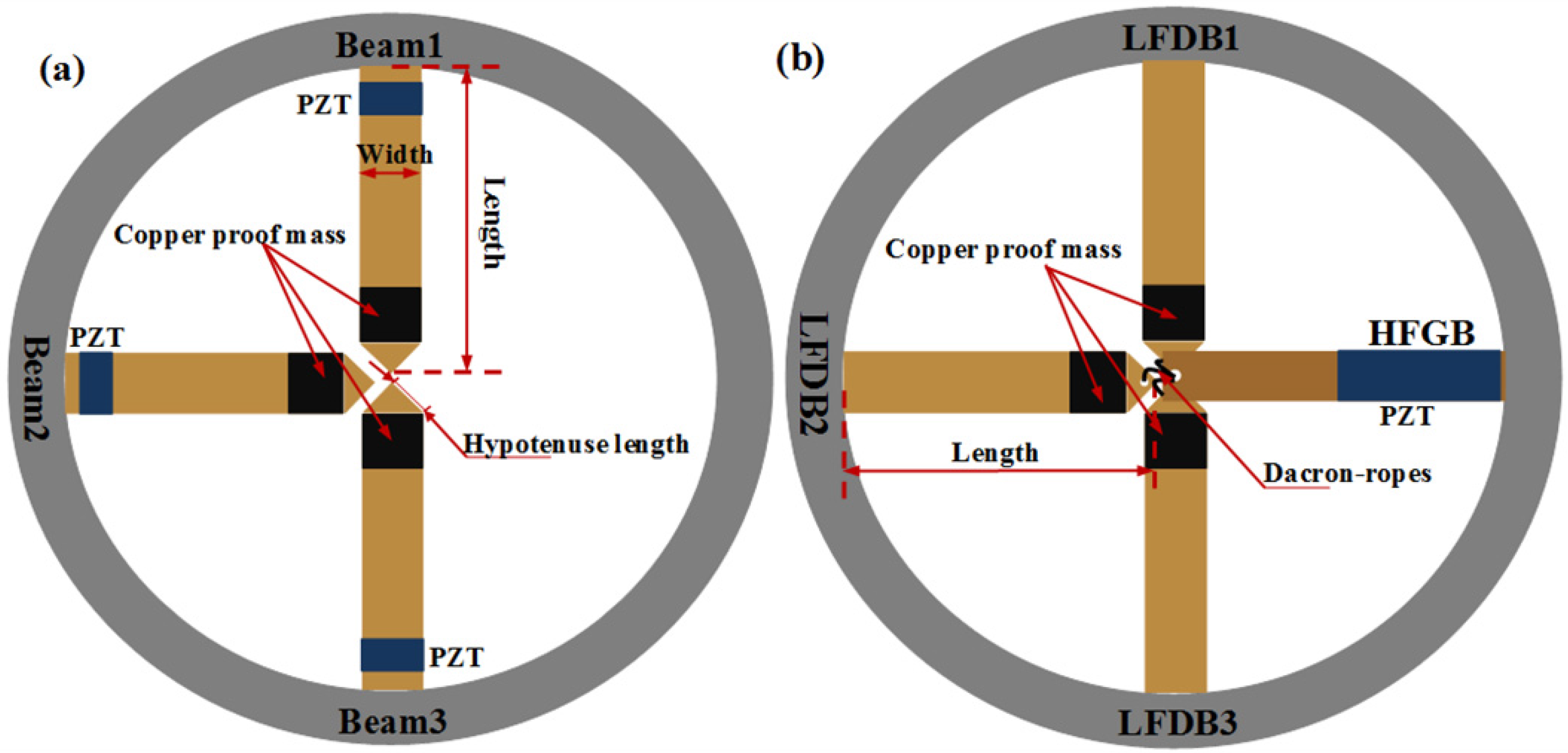
Figure 1. (a) Architecture of the novel wideband vibration energy harvester (VEH), (b) architecture, (c) schematic model, and (d) operation mechanism of the individual low-frequency driving beam (LFDB) driving a high-frequency generating beam (HFGB) VEH system.
Applsci 06 00402 g001
Figure 2. Equivalent circuit of an arrays of beams vibration energy harvester (AB-VEH) system (a) in parallel and (b) in series.
Applsci 06 00402 g002
Figure 3. Equivalent circuit of the novel ropes-driven wideband VEH system.
Applsci 06 00402 g003
Figure 4. Experimental geometric construction of AB-VEH (a) and novel VEH (b) systems.
Applsci 06 00402 g004
Figure 5. Experimental setup of the novel piezoelectric vibration energy harvester (PVEH) system. (a) Precise adjustment system; (b) vibration testing setup.
Applsci 06 00402 g005
Figure 6. Normalized output power of AB-VEH connected in (a) parallel and (b) series with optimal load resistance.
Applsci 06 00402 g006
Figure 7. Normalized output power corresponding to individual and multi-LFDBs of novel VEH with optimal load resistance.
Applsci 06 00402 g007
Figure 8. Parameters effects on the frequency response of the proposed wideband VEH system: (a) demonstrates the effects due to changing acceleration; (b) demonstrates the effects due to changing rope margin; (c) demonstrates the effects due to changing stiffness of the driving beam (DB).
Applsci 06 00402 g008
Figure 9. Adjustable performance by changing (a) acceleration, (b) rope margin, and (c) rope margin and LFDBs’ stiffness, simultaneously.
Applsci 06 00402 g009
Table 1. The parameters of AB-VEH and novel VEH systems.
ParameterBeam 1Beam 2/LFDB1Beam 3/LFDB2LFDB3HFGB
Length (mm)50.346.848.348.339.2
Width (mm)15.015.015.015.014.0
Thickness (mm)0.40.30.40.40.5
Hypotenuse length (mm)17.819.819.919.0-
Proof mass (g)2.21.22.22.2-
Frequency (Hz)58.864.469.875.6206.8

