Article

Moving Object Tracking and Its Application to an Indoor Dual-Robot Patrol

Department of Communications, Navigation and Control Engineering, National Taiwan Ocean University, Keelung 20224, Taiwan
*
Author to whom correspondence should be addressed.
Appl. Sci. 2016, 6(11), 349; https://doi.org/10.3390/app6110349
Submission received: 15 August 2016 / Revised: 23 October 2016 / Accepted: 4 November 2016 / Published: 12 November 2016

Abstract

:
This paper presents an application of image tracking using an omnidirectional wheeled mobile robot (WMR). The objective of this study is to integrate image processing of hue, saturation, and lightness (HSL) for fuzzy color space, and use mean shift tracking for object detection and a Radio Frequency Identification (RFID) reader for confirming destination. Fuzzy control is applied to omnidirectional WMR for indoor patrol and intruder detection. Experimental results show that the proposed control scheme can make the WMRs perform indoor security service.

1. Introduction

With the development of human civilization and technologies, human life has changed a lot in the past few decades. One of the technologies that has progressed is robot systems. Intelligent robots are now used in daily life for entertainment, medical care, home security, and services in other fields. Intelligent robots integrate electronics, mechanics, control, automation, and communication technologies. Different types of robots have been developed in recent years to meet a variety of needs. The development of robot systems combines the theoretical expertise of many professionals. Related studies and applications are extensive, including obstacles avoidance, path planning, and visual image processing. How to improve the accuracy of a robot’s performance is one of the main foci in the field of intelligent robotic control. Omnidirectional wheeled mobile robot (WMR) is one of the mobile robot models that has been discussed widely. It has more advantages than normal WMR, such as mode of action, easy control, and high mobility [1,2,3,4,5]. Designing an intelligent system for omnidirectional WMR to search and track moving objects automatically is the objective of this study. When omnidirectional WMR is working, one must consider how to adapt to the environment and improve the efficiency of the mission. Many researchers have presented studies on intelligent robot control. Studies on intelligent robots include aspects such as obstacle avoidance, path planning, object tracking, etc. Lin implemented obstacle avoidance and Zigbee control functions for an omnidirectional mobile robot [6]. Tsai applied a omnidirectional mobile robot to remote monitoring [7]. Juang presented wheeled mobile robot obstacle avoidance and object following control based on real-time image tracking and fuzzy theory [8]. Paola proposed multi-sensor surveillance of indoor environments by an autonomous mobile robot. The robot was equipped with a monocular camera, a laser scanner, encoders, and an RFID device, and used a multi-layer decision and control scheme. Fuzzy logic was applied to integrate information from different sensors [9]. Zhong utilized an omnidirectional mobile robot for map building applications [10]. Lee et al. proposed three fuzzy control systems for obstacle avoidance, target seeking, and wall following. The fuzzy control system was integrated in the mobile robot and applied to home security patrol [11]. Chen presented intelligent strategies for a WMR to avoid obstacles and move to a target location. In a short-distance obstacle avoidance model, the WMR utilized signals from ultrasonic sensors to avoid obstacles. In a target-driven obstacle avoidance model, fuzzy theory with sensor signals was used to control the speed of the WMR and make it move to a target location [12].
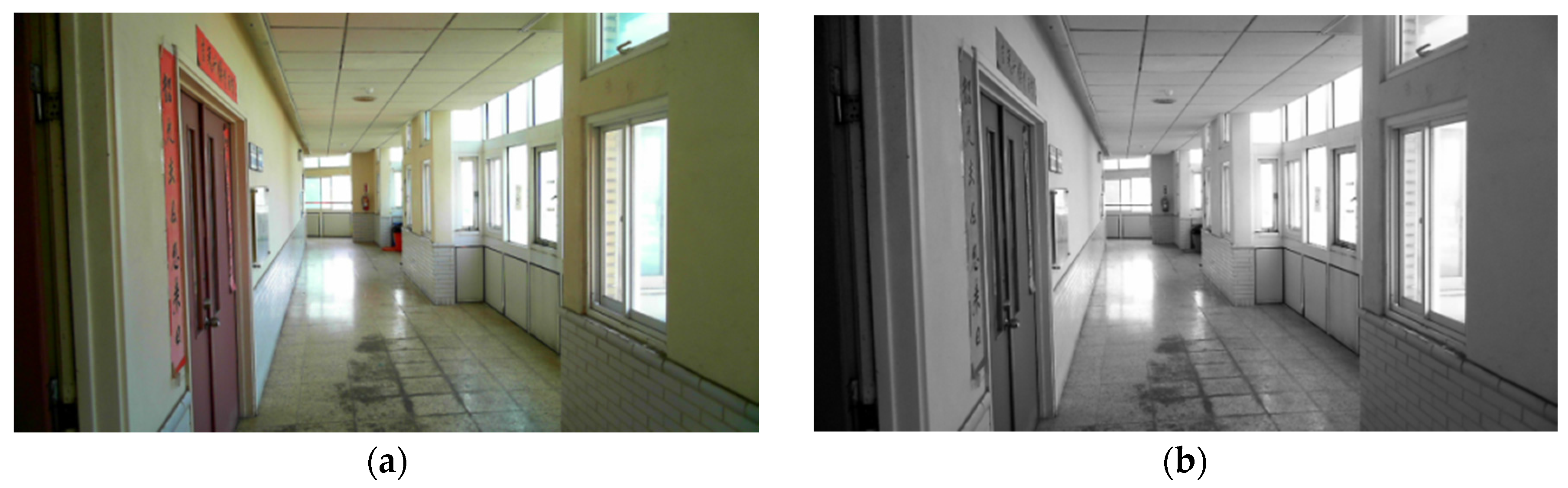
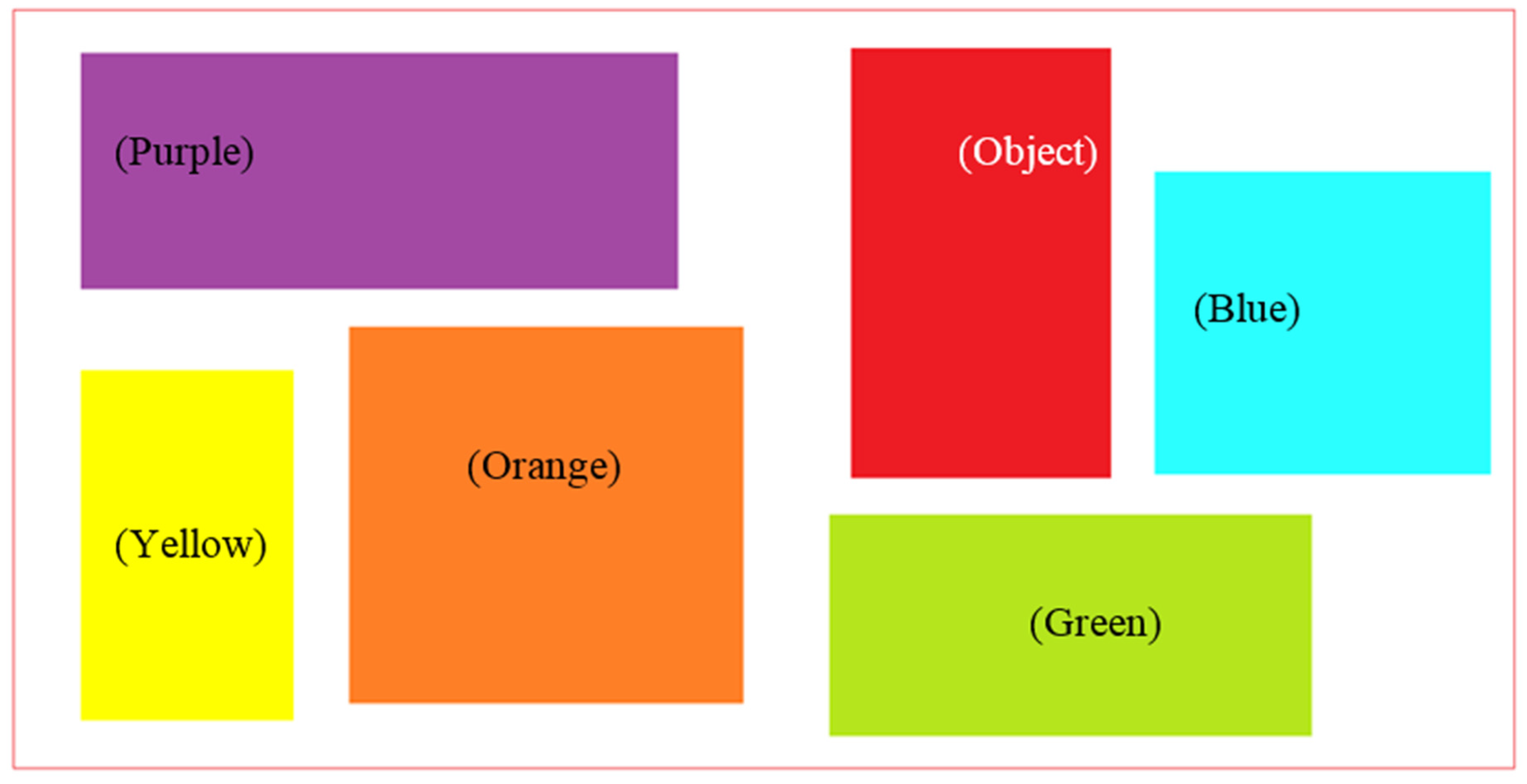
One of the purposes of this study is to use real-time images from a webcam to provide target recognition and tracking, which includes color identification of a destination room. In image recognition, we use the fuzzy color histogram classification, which can quickly and accurately recognize environment background color and patterns. Martinez introduced fuzzy naturals-based histograms on fuzzy color spaces. Histograms were fuzzy probability distributions on a fuzzy color space, where the fuzzy probability was calculated as the quotient between a fuzzy natural number and the number of pixels in the image, the former being a fuzzy (non-scalar) cardinality of a fuzzy set [13]. Chang developed a fuzzy color histogram generated by a self-constructing fuzzy cluster that can reduce the interference from lightness changes for the mean shift tracking algorithm. Their experimental results showed that the tracking approach was more robust than the conventional mean shift tracking algorithm and the computation time only increased a little [
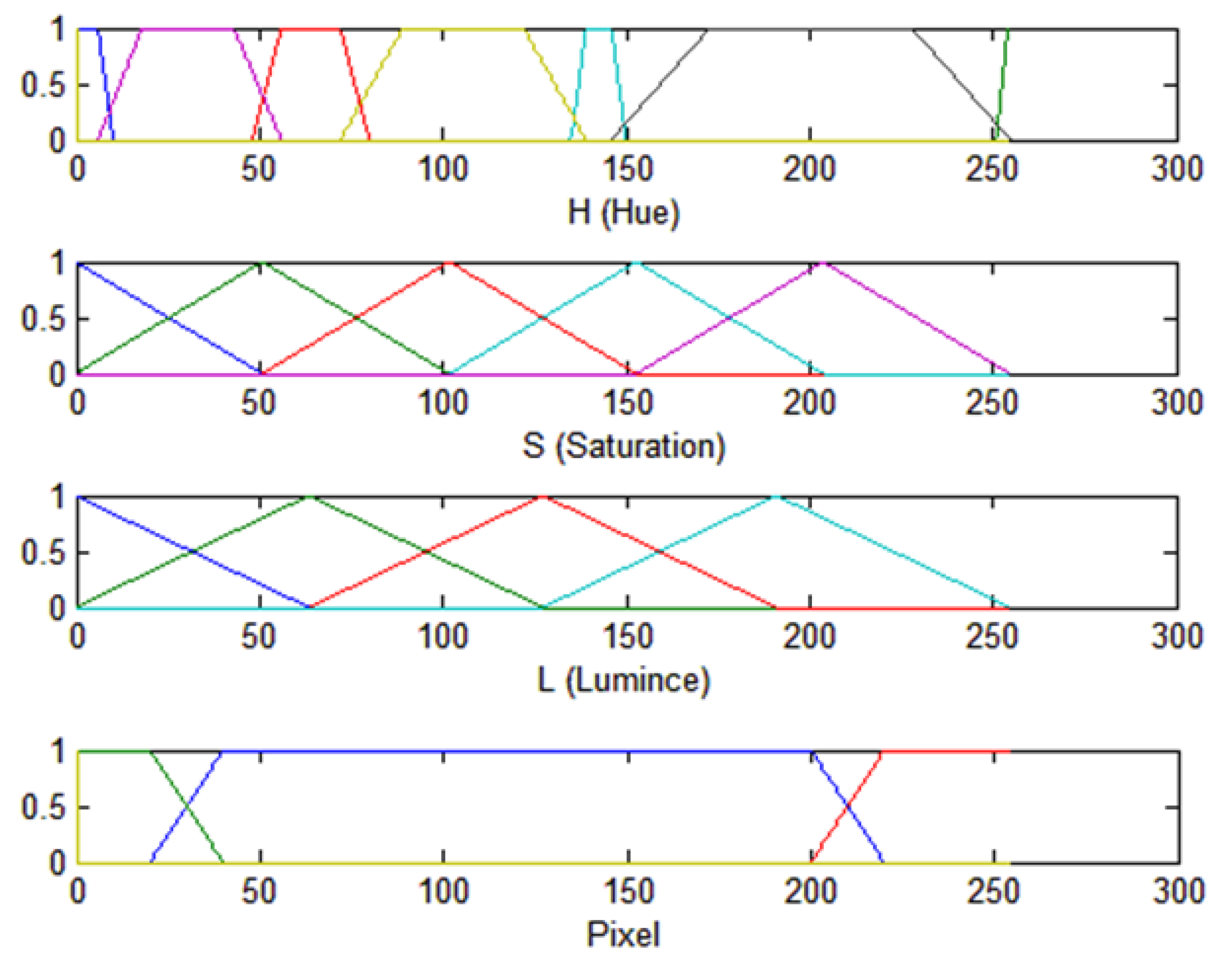
14]. Puranik presented image processing that can be either an image or a set of characteristics or parameters related to an image. The color vision system first classified pixels in a given image into a discrete set of color classes. The objective was to produce a fuzzy system for color classification and image segmentation with the least number of rules and the minimum error rate. Fuzzy sets were defined for the H, S, and L components of the hue, saturation, and lightness (HSL) color [15]. Chien proposed an image segmentation scheme based on a fuzzy color similarity measure to segment out meaningful objects in an image according to human perception. The scheme defined a set of fuzzy colors based on the HLS color coordinate space. Each pixel in an image is represented by a set of fuzzy colors that were the most similar colors in the color palette selected by humans. Then, a fuzzy similarity measure was proposed for evaluating the similarity of fuzzy colors between two pixels. He recursively merged adjacent pixels to form meaningful objects by the fuzzy similarity measure until there was no similar color between adjacent pixels [16]. Cho proposed a scheme with swimmer detection and swimmer tracking stages. The detection stage began with employing the mean-shift algorithm to cluster input image, and then choosing the sets using graphical models to train the Gaussian mixture model. Finally, swimmers can be detected in a model-based way [17].
To identify a human object, Wong presented a human detection algorithm embedded into a thermal imaging system to form a fast and effective trespasser detection system for smart surveillance purpose. A pattern recognition technique was employed whereby the human head was detected and analyzed for its shape, dimension, and position [18]. Zalid presented data fusion acquired from a CCD camera and a thermal imager. The fusion was realized by means of spatial data from a TOF camera to ensure “natural” representation of a robot’s environment; thus, the thermal and color-related data comprised one stereo image presented to a binocular, head-mounted display [19]. Kraubling developed four methods to identify persons during tracking. The first method used color information extracted from camera images to distinguish between persons, based on the color of the clothes they wear. The second method used reflectance intensities, which can be provided directly by laser range sensors. The third method was also based on camera information, but employs a probabilistic shape and motion model for each person it tracks, in order to distinguish between them. The last one used a network of dedicated sensors, which directly transmit identification information for each person [20]. Tzeng proposed a system containing three components: image capture, image pre-processing, and environment determination. The image was first captured by a webcam. Then image pre-processing was used to obtain the moving pixel area by Background Subtraction in order to conduct smoothing filtering and image binary. Finally, moving objects were determined by calculating the variations within an image moving region [21]. Chung developed a computer vision based on moving object detection and automatic tracking system. He used the temporal frame difference technique to find the moving pixels for moving object detection. The temporal frame difference technique can quickly locate all moving pixels and improve computation efficiency. However, if there is a dynamic background, moving pixels will include the background; therefore he first applied global motion compensation in order to reduce the moving background effect. Then he calculated the standard deviation and the maximum of each block. After statistical analysis, the moving object area can be obtained. The use of mean shift iteration can accurately and efficiently calculate the most similar image mass center location and accomplish tracking moving object [22]. Machida et al. proposed a tracking control system of human motion with Kinect onboard a mobile robot. The 3D position information on humans obtained from Kinect can be used to control the velocity and attitude of the robot. The Kalman filter was applied to reduce the noise and estimate human’s motion state. The mobile robot was controlled to track moving humans in the view of Kinect [23]. Šuligoj et al. proposed a method of frame relative displacement in which a multi-agent robot can be used for tracking, tooling, or handling operations with the use of stereo vision in an unstructured laboratory environment. The relative position between the robot’s tool center point and the object of interest is essential information to the robot system. The system has two robot arms: one carries a stereo vision camera system and the other is guided in relation to the object of interest. A marker is used for navigation between the robot and the object of interest. Image processing, marker detection, 3D coordinates extraction, coordinate system transformations, offset coordinates calculation, and communication are handled using the C++ program and TCP/IP protocol [24]. The differences in our study are that a cheaper webcam is applied to catch moving objects by the use of the mean shift method. Information on the detected object can be sent to a control center via well-installed Wi-Fi communication. Omnidirectional WMR, instead of a two-wheel- or four-wheel-driven robot, is utilized for easy direction control.
An intelligent omnidirectional WMR integrates many functions, such as environment sensing, dynamic decision-making and tracking, behavior control and executing, etc. In WMR movement control, the ultrasound sensor is one of the most used sensors to avoid obstacles [8]. In [25], fuzzy logic was used to form parking behavior patterns for path planning. Reference values were searched by a genetic algorithm and applied to obtain the optimal WMR tracking performance. Lu applied a laser sensor and A* algorithm to a WMR that can avoid obstacles and planed moving path [5]. Many researchers have tried to improve robot systems to make them easy to control, which will help humans and robots to interact more harmoniously in daily life. The main purpose of this study is to integrate a webcam, ultrasound sensor, and RFID reader in two omnidirectional WMRs for indoor patrol. In path planning, the WMR used a webcam to search predefined doors for destination tracking and used ultrasound sensors for obstacle detection. Fuzzy color histogram classification is used to separate moving objects from the background environment. In this study, a mean shift algorithm is applied to classify the object from the background and track moving objects. An RFID reader is used to read the tag and check whether it is the destination or not. By image recognition and path planning, the omnidirectional WMR can automatically search and track moving objects. Omnidirectional WMR is a nonlinear model; a dynamic equation is needed for system analysis and control regulation design. The fuzzy system is applied in fuzzy controller design for its nonlinearity, and the control scheme is simple and flexible. Ultrasonic sensors receive reflecting values when the WMR moves, then these values are used to determine the locations of the obstacles and as inputs of the fuzzy controller to avoid obstacles. The mean shift method can find the highest color density of sample points from the fuzzy color space of the target object and keep tracking it. The contributions of this study are as follows: the proposed control scheme can control omnidirectional WMR to search and track moving objects with real-time image processing and plan a path automatically; the RFID reader identifies destination again when omnidirectional WMR moves forward to the destination; obstacles avoidance is controlled by a fuzzy controller; intruders can be tracked by the mean shift algorithm, and the image of the intruder can be sent to the control center via Wi-Fi communications from the robot; and the proposed dual robot patrol system can perform indoor security service and release human resources.
This paper is divided into five sections. The first section is the introduction of this paper. The other five sections are as follows. Section 2 introduces image processing methods, which include fuzzy color space and mean shift tracking. Section 3 introduces the structure of the control scheme. Fuzzy control is applied to obstacle avoidance and tracking moving objects. RFID is applied to verify the destination. Section 4 shows the results of this study. By image processing and path planning, the omnidirectional wheeled mobile robot can automatically search for and track moving objects. Section 5 describes the advantages and disadvantages of the method based on the results of this study and then conclusions are given. This section also provides future research directions and suggestions.

2. Image Processing

2.1. Color Space Transformation

The webcam captures images in Red, Green, Blue (RGB) color space. Then the RGB image is transformed to HSL color space by code transform processing [26]. RGB color space uses additive color by primary color to produce many colors, but colors produced by the primary color component are not so intuitive. HSL color space includes the hue, saturation, and lightness. This space is similar to human vision. RGB color space values are transformed to HSL color space values by
H = { 0 ° i f   max = min 60 ° × g b max min + 0 ° i f   max = r   a n d   g b 60 ° × g b max min + 360 ° i f   max = r   a n d   g < b 60 ° × b r max min + 120 ° i f   max = g 60 ° × r g max min + 240 ° i f   max = b
L = 1 2 ( max + min )
S = { 0 i f   = 0   o r   max = min max min max + min i f   0 < l 1 2 max min 2 ( max + min ) i f   l > 1 2 .
In the process of catching visual image, we used a Microsoft LifeCam studio webcam, and put it on the photographer’s left shoulder. The camera is used for target tracking and pattern recognition. Figure 1 shows the images in the RGB and HSL color spaces. In target pattern processing, we use RGB color space to decide the R, G, and B values for getting the color that is needed. This method can help us to filter out the colors that are not needed.

2.2. Fuzzy Color Histogram Classification

Color image segmentation using fuzzy classification is a pixel-based segmentation method [27]. A pixel is assigned a specific color by the fuzzy system; any given pixel is then classified according to the segments it lies in. Color classification can recognize all colors from the image and define the specific color. To define the specific color, a color spectrum is used to decide the threshold of hue, saturation, and lightness. When we have established the environmental background color with known samples, after training the webcam can automatically capture non-sample colored objects. In this study we used this method to detect desired doors and objects. An example is shown in Figure 2, where these blocks are in different colors. If we need to find a non-defined color, we must first establish the known pattern color. The hue value, saturation value, and lightness value are all preset. In Figure 2, a red frame is used to circle detected blocks in the image frame. The red object is the unknown object. Then the threshold is applied, as shown in Table 1. The values of the known color are put into the fuzzy rules.
The proposed fuzzy color classification system has three inputs and one output. H, S, and L are inputs of the fuzzy system, and the data points are the values of its H, S, and L. H fuzzy sets are Orange, Yellow, Green, Blue, Purple, Object, and Object 1. S fuzzy sets are S (somber), G (gray), P (pale), D (dark), and DP (deep). L fuzzy sets are Li (light), LU (luminous), M (medium), and B (bright). Output EO is the turning pixel for environment background or objects, fuzzy sets are EB (Environment Background), OB1 (Object 1), and OB (Object). Fuzzy rules are shown as follows, and the fuzzy sets are shown in Figure 3. The undefined object color (Red) is classified as shown in Figure 4 and the values are shown in Table 2.
  • Rule 1: If H is Orange and S is S and L is Li, then EO is EB.
  • Rule 2: If H is Yellow and S is S and L is Li, then EO is EB.
  • Rule 3: If H is Green and S is S and L is Li, then EO is EB.
  • Rule 4: If H is Blue and S is S and L is Li, then EO is EB.
  • Rule 5: If H is Purple and S is S and L is Li, then EO is EB.
  • Rule 6: If H is Object and S is S and L is Li, then EO is EB.
  • Rule 7: If H is Object 1 and S is G and L is LU, then EO is EB.
  • Rule 8: If H is Orange and S is G and L is LU, then EO is EB.
  • Rule 9: If H is Yellow and S is G and L is LU, then EO is EB.
  • Rule 136: If H is Green and S is DP and L is B, then EO is EB.
  • Rule 137: If H is Blue and S is DP and L is B, then EO is EB.
  • Rule 138: If H is Purple and S is DP and L is B, then EO is EB.
  • Rule 139: If H is Other 1 and S is DP and L is B, then EO is OB1.
  • Rule 140: If H is Other and S is DP and L is B, then EO is OB.
In fuzzy color space, the hue component (H) represents the color tone (red or blue), saturation (S) is the amount of color (vivid red or pale red), and lightness (L) is the amount of light (it allows us to distinguish between a dark color and a light color) [14]. Fuzzy color space transforms the environmental background color and calculates the average distribution of hue, saturation, and lightness (Figure 5). It isolates an object from the background environment, and obtains the image of the object as an intruder.

2.3. Mean Shift Tracking

Mean shift algorithm is a simple interactive procedure that shifts each data point to the average of data points in its neighborhood. For Gaussian kernels, mean shift is a gradient mapping. Convergence is guaranteed for mean shift iterations. Cluster analysis is treated as a deterministic problem of finding a fixed point of mean shift that characterizes the data [28]. The pixel from HSL color space is used in clustering. Similar colors of the pixel will be clustered into the same group. Each pixel in the image corresponds to a point in fuzzy color space. Mean shift can obtain locally similar colors of the pixel to achieve the maximum density clustering effect [29]. The fuzzy color histogram of a target is constructed to characterize the tracked object. The target is represented by a square region in the image. By the use of the trained fuzzy cluster and a kernel function, weighting factors with respect to all pixels within the square region are calculated. Mean shift can find the highest color density of sample points from the fuzzy color space of the target objects, and the objects can be tracked continuously. Given the position of the detected moving object, we want to extract its color distribution information. Let pattern image color density function be q(u), and the candidate image in the color density be a function of position y; p (u, y) is used to find the position of y, such that p (u, y) and q(u) have the highest similarity [21,30].
Pattern image color density function is:
q ( u ) = C u = 1 m k ( x i 2 ) δ [ b ( x i ) u ] ,
where u is the HSL full-color image, x i is the object position of pattern image (from fuzzy color classification), b ( x i ) is the transform of the corresponding color index of x i , k ( x i 2 ) is the kernel function, C is the normalization factor, δ (x) is the Kronecker delta function, and δ ( x ) = { 0 ,   i f   x 0 1 ,   i f   x = 0 .
Candidate image color density function is:
p ( u , y ) = C h u = 1 n h k ( x i y h 2 ) δ [ b ( x i ) u ] ,
where xi is the real object position of candidate image, C h is the normalization factor, h is the kernel radius length, y is the initial position of the candidate image, and k ( y x i h 2 ) is the kernel function. The highest estimated Bhattacharyya coefficient is:
ρ ( y ) ρ [ p ( u , y ) , q ( u ) ] = u = 1 m p ( u , y ) q ( u ) .
Taylor expansion of Equation (6) is applied to deduce the color image density (patterns and candidate) and to make the Bhattacharyya coefficient have the maximum similarity value.
ρ [ p ( u , y 1 ) ] ρ [ p ( u , y 0 ) ] + ρ [ p ( u , y 0 ) ] [ p ( u , y ) ] p ( u , y 0 ) ]
ρ [ p ( u , y 1 ) ] 1 2 u = 1 m p ( u , y 0 ) q ( u ) + 1 2 u = 1 m p ( u , y ) q ( u ) p ( u , y 0 )
ρ [ p ( u , y 1 ) ] 1 2 u = 1 m p ( u , y 0 ) q ( u ) + C h 2 u = 1 m w i k ( x i y h 2 )
w ( x i ) = u = 1 m δ [ b ( x i ) u ] q ( u ) p ( u , y 0 )
w ( x i ) are the weights of candidate image at x i . In order to obtain the greatest similarity, the Bhattacharyya coefficient in Equation (9) must be at its maximum. According to the probability density function estimation in [22], the Epanechnikov kernel function resulting average of all error (Average Global Error) will be minimal, thus the Epanechnikov kernel function is chosen as the core function. The Epanechnikov kernel function is:
k ( x ) = { 1 2 c d 1 ( d + 2 ) ( 1 x 2 ) i f x 1 0 otherwise ,
where d is the dimensions of space, C d is the dimensional space, and the unit area of the circle is C d = π . Kernel density estimation is:
f ( x ) = i = 1 n k ( x i - x h ) w ( x i ) h d i = 1 n w ( x i ) .
Let k ( x ) = k ( x 2 ) . The gradient of kernel density is f ( x ) . If g ( x ) is defined as k ( x ) and g ( x ) = k ( x ) , then
f ( x ) = 2 i = 1 n   ( x i - x ) g ( x i - x h 2 ) w ( x i ) h d + 2 i = 1 n   w ( x i ) = 2 h 2 [ i = 1 n g ( x i - x h 2 ) w ( x i ) h d i = 1 n   w ( x i ) ] [ i = 1 n   ( x i - x ) g ( x i - x h 2 ) w ( x i ) i = 1 n g ( x i - x h 2 ) w ( x i ) ] .
The average motion vector is:
M ( x ) = [ i = 1 n x i g ( x i - x h 2 ) w ( x i ) i = 1 n g ( x i - x h 2 ) w ( x i ) x ] .
An example of the mean shift method is shown in Figure 6.
Using the Epanechnikov kernel average displacement vector with the average maximum Bhattacharyya coefficient simplifies the computation, so we can calculate the average displacement and find the pattern image that has the greatest similarity to the candidate image. This method can quickly and effectively identify the image with the most similar moving object candidate, and track the image. Procedures of the mean shift are shown as follows:
  • Step 1: Calculate the color image density of the patterns.
  • Step 2: Calculate the color image density of the candidate.
  • Step 3: Substitute the color image density (patterns and candidate) into Equation (6) and obtain the Bhattacharyya coefficient at y 0 .
  • Step 4: Obtain the w ( x i ) weights using Equation (10).
  • Step 5: From M ( y 0 ) = [ i = 1 n x i g ( x i - y 0 h 2 ) w ( x i ) i = 1 n g ( x i - y 0 h 2 ) w ( x i ) y 0 ] , calculate a new position of the candidate image y 1 = [ i = 1 n x i g ( x i - y 0 h 2 ) w ( x i ) i = 1 n g ( x i - y 0 h 2 ) w ( x i ) ] .
  • Step 6: Use new point y 1 to update { p ( u , y 1 ) } u = 1 ... m and ρ(y).
  • Step 7: If ρ [ p ( u , y 1 ) , q ( u ) ] < ρ [ p ( u , y 0 ) , q ( u ) ] , revise y 1 = 1 2 ( y 0 + y 1 ) .
  • Step 8: If ( y 1 y 0 ) < ε , stop iteration, otherwise update y 0 and let y 0 = y 1 and return to Step 2.
Through iteration of the above steps, we can calculate the similarity to the highest candidate image to achieve effective tracking. Figure 7 shows an example of a static background with a moving object. Figure 8 shows an example of a dynamic background with a moving object.

3. Control Scheme

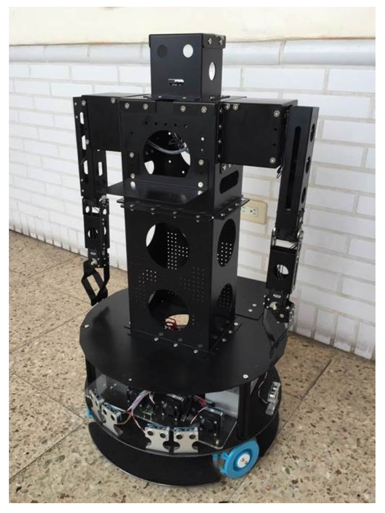
The proposed control scheme is performed through experiment verification by an omnidirectional WMR, as shown in 
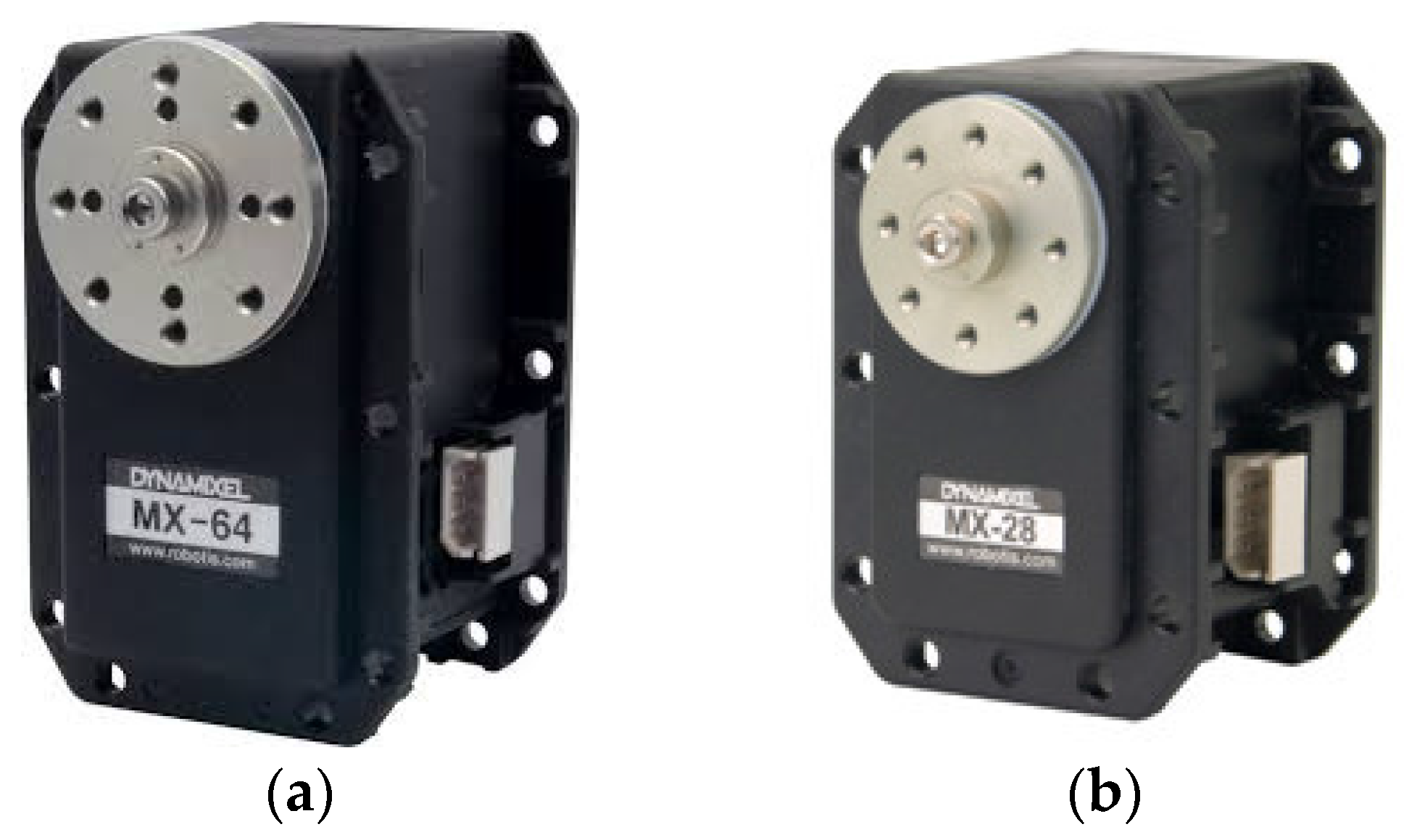
Figure 9. The omnidirectional WMR’s chassis size is 240 mm radius. Three omni wheels are configured in space 120° and three 12V-DC motors are installed to provide rated torque of 68 mNm. The robot is 600 mm in length, 400 mm in width, and 850 mm high. It has mechanical arms and fingers that are able to grip things; their length is 470 mm and 150 mm, respectively. The robot arms have six MX-64 motors, two in the shoulder and one in the elbow on both sides. MX-64 is 40.2 mm in length, 41 mm in width, and 61.1 mm high. Its stall torque is 6.0 mNm. There are two MX-28 motors at the wrist on both sides. MX-28 is 35.6 mm in length, 35.5 mm in width, and 50.6 mm high. Its stall torque is 2.5 mNm. The motors are shown in Figure 10.
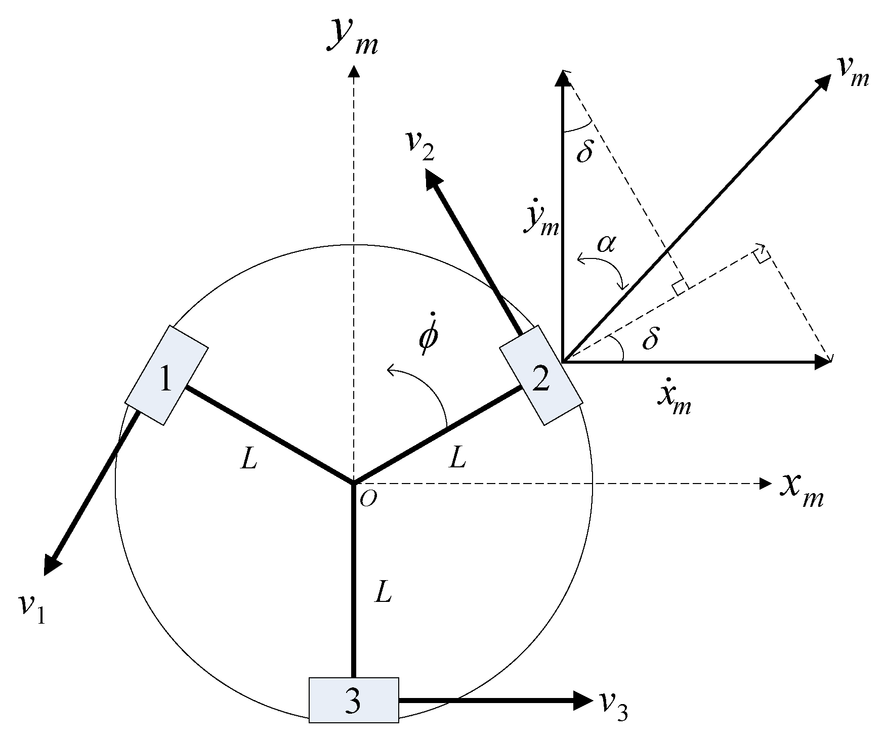
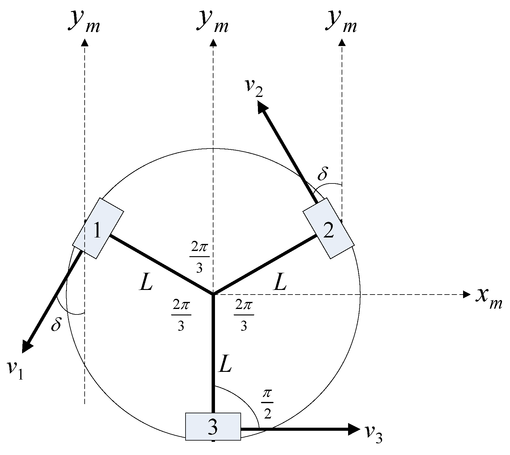
The omnidirectional WMR kinematic model [6,7] is described as follows. First, we assume the WMR is set on a coordinate system as shown in Figure 11, where v m is the speed of target direction, v 1 , v 2 , v 3 are the forward speed of each wheel, x ˙ m , y ˙ m are the decomposition of v m , and α is the angle between the target and WMR.
In Figure 12, we know v m vector consists of x ˙ m and y ˙ m . So we can get the v 2 speed for the v m direction as in Equation (15):
v 2 = sin ( δ ) x ˙ m + cos ( δ ) y ˙ m + L ϕ ˙ = sin ( 30 ) v m sin ( α ) + cos ( 30 ) v m cos ( α ) = ( 0.5 sin ( α ) + 0.866 cos ( α ) ) v m .
Then we also know how to get v 1 and v 3 for v m direction as in Equations (16) and (17):
v 1 = ( 0.5 sin ( α ) 0.866 cos ( α ) ) v m
v 3 = sin ( α ) v m .
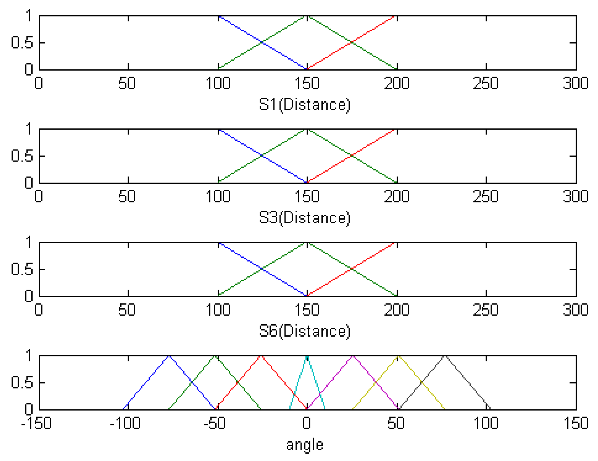
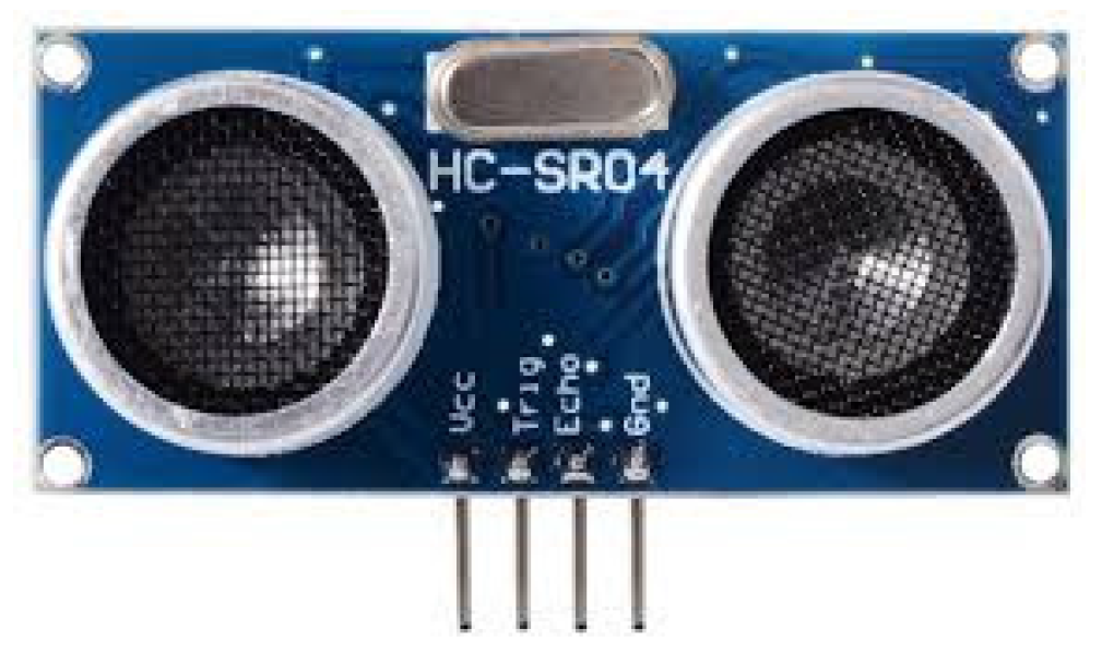
There are six ultrasonic sensors installed in front of the second layer of the chassis and they are PARALLAX PING ultrasonic distance sensor. The detection distance is approximately 2 cm to 3 m, the burst frequency is 40 KHz, the current is 30 mA, and the voltage is 5 V, as shown in Figure 13. The sensors are used to measure the distance and detect and avoid obstacles. Fuzzy theory is applied to obstacle avoidance control. The fuzzy control structure has four inputs and one output. Ultrasonic signals S1, S3, and S6 are inputs and the value is distance. Fuzzy sets are F (far), M (medium), and N (near). Output DA is the angle for left or right; fuzzy sets are VL, L, S, R, and VR. Fuzzy rules are shown as follows, and the fuzzy sets are shown in Figure 14.
  • Rule 1: If S1 is N and S3 is N and S6 is M, then DA is VR.
  • Rule 2: If S1 is N and S3 is N and S6 is F, then DA is VR.
  • Rule 3: If S1 is N and S3 is M and S6 is N, then DA is VR.
  • Rule 4: If S1 is N and S3 is M and S6 is M, then DA is VR.
  • Rule 5: If S1 is N and S3 is M and S6 is F, then DA is R.
  • Rule 6: If S1 is N and S3 is F and S6 is N, then DA is R.
  • Rule 7: If S1 is N and S3 is F and S6 is M, then DA is R.
  • Rule 8: If S1 is N and S3 is F and S6 is F, then DA is S.
  • Rule 9: If S1 is M and S3 is N and S6 is N, then DA is L.
  • ….
  • Rule 26: If S1 is F and S3 is F and S6 is M then DA is S.
  • Rule 27: If S1 is F and S3 is F and S6 is F, then DA is S.
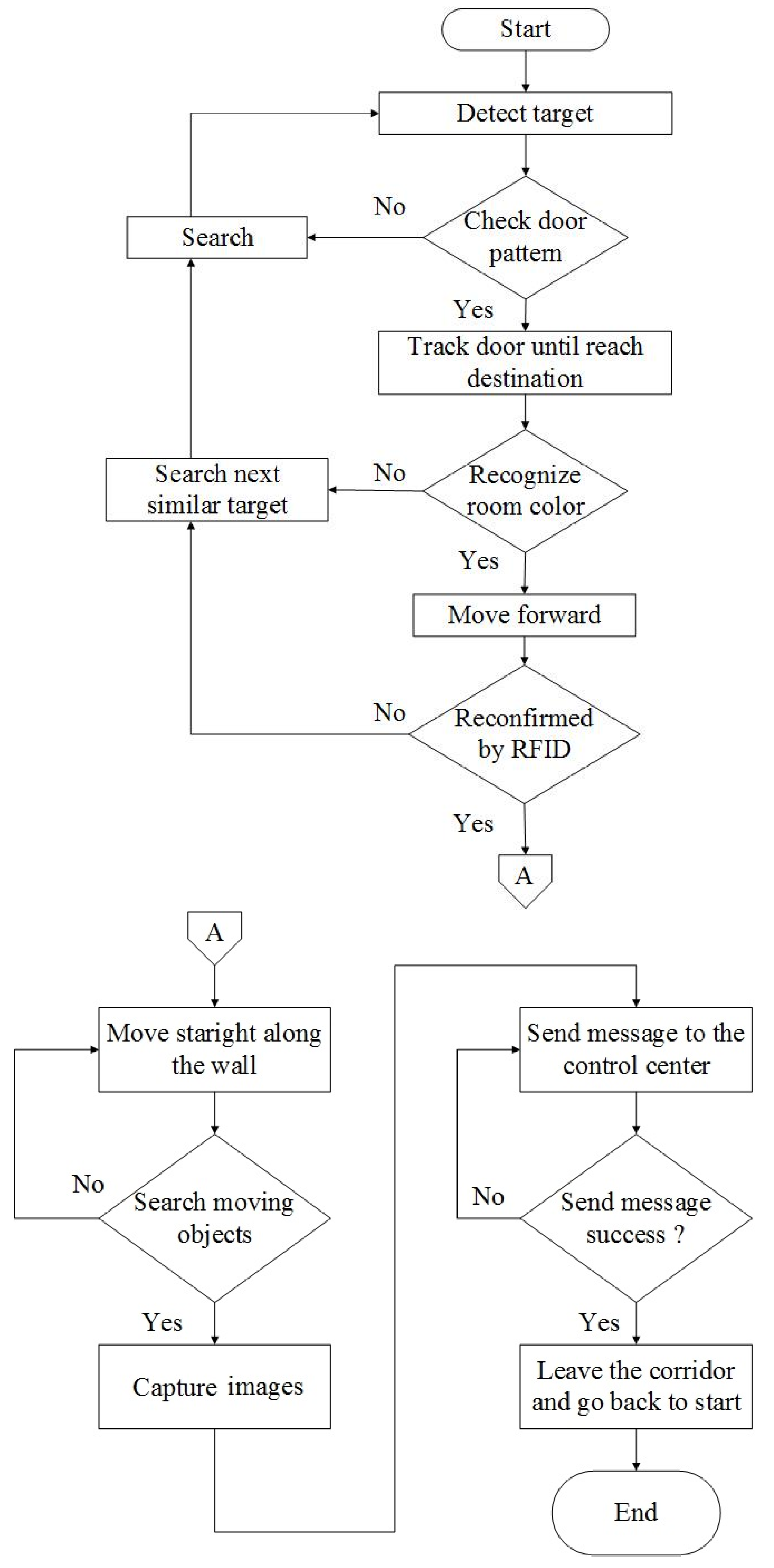
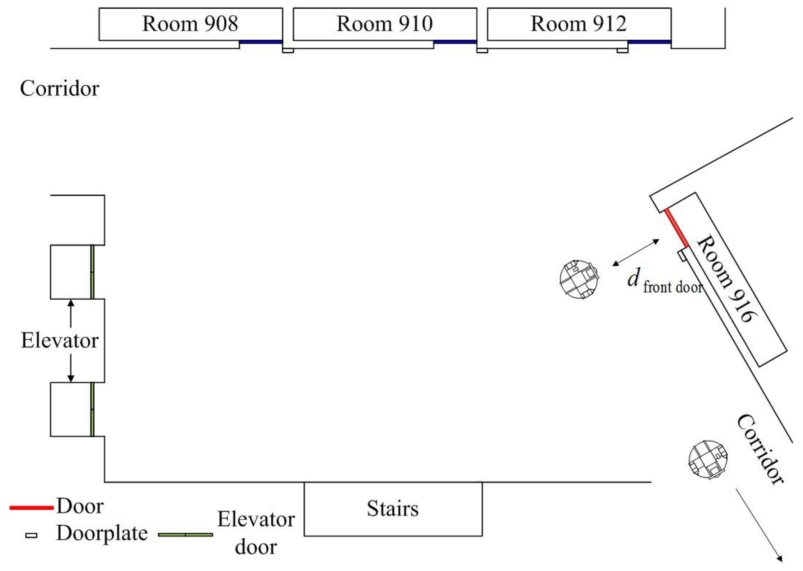
A flowchart of the control sequence is shown in Figure 15. First, the robot will search for the predefined door in the experimental environment. When the robot detects the specified color target, it moves forward. On the way to this objective, the robot will correct its path by detecting the image range at all times. When the robot reaches the specified distance from the door, it will correct its angle to aim at the door. Then it recognizes the room color and checks whether it has reached the destination or not. If the room color represents the desired destination, the robot moves to the door and RFID, as shown in 
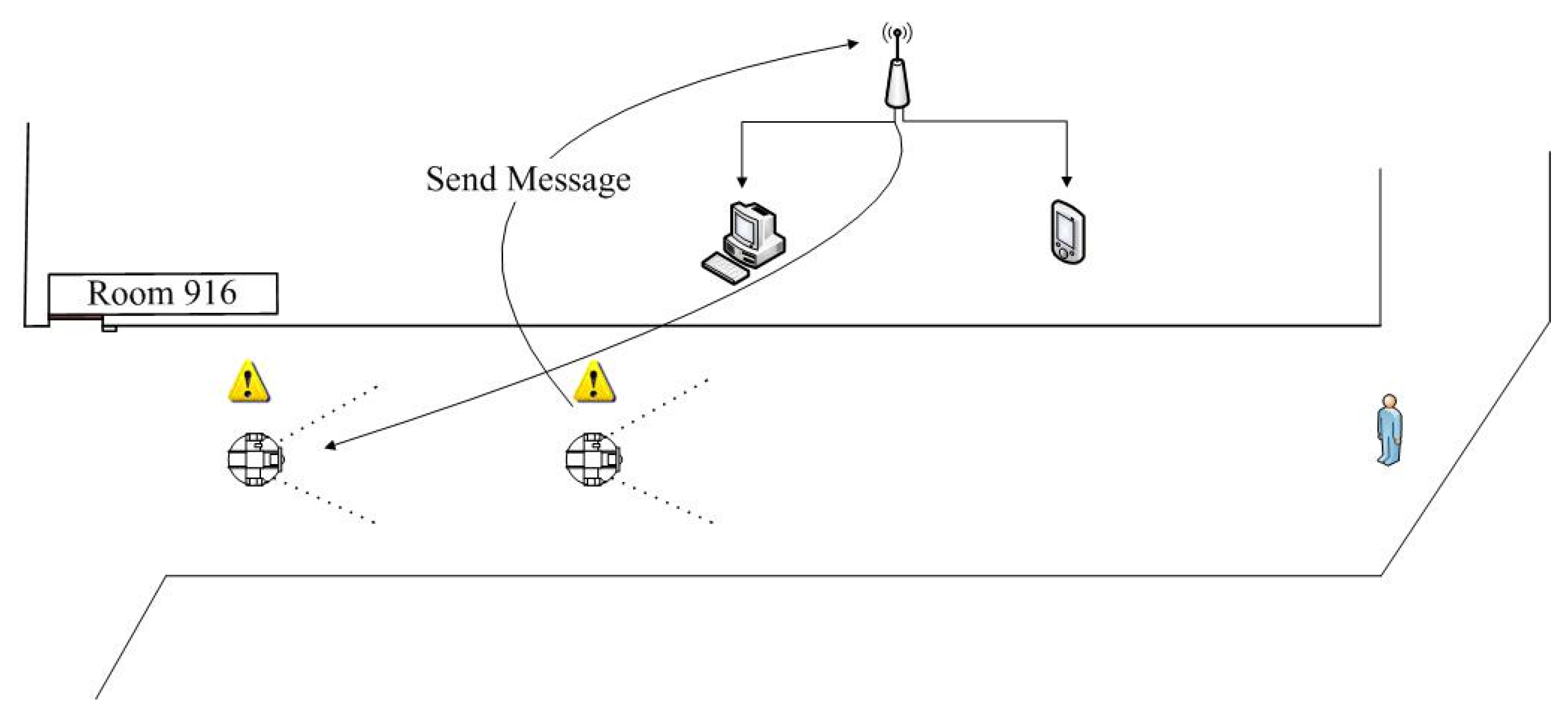
Figure 16, reconfirms at the specified distance to verify the target. If the room is not the destination, the robot will search for the next similar target. The RFID will verify the destination again and make sure it is true. When the robot is 500 mm away from the door, the robot will turn to patrol the corridor. When an object appears in the corridor and is intercepted, an image of the object will be transmitted to the control center via Wi-Fi. Staff in the control center can check the object; if it is an intruder they will send a security guard to the scene to ensure safety. If the object is not an intruder, the robot will return to the starting position along the planned route.
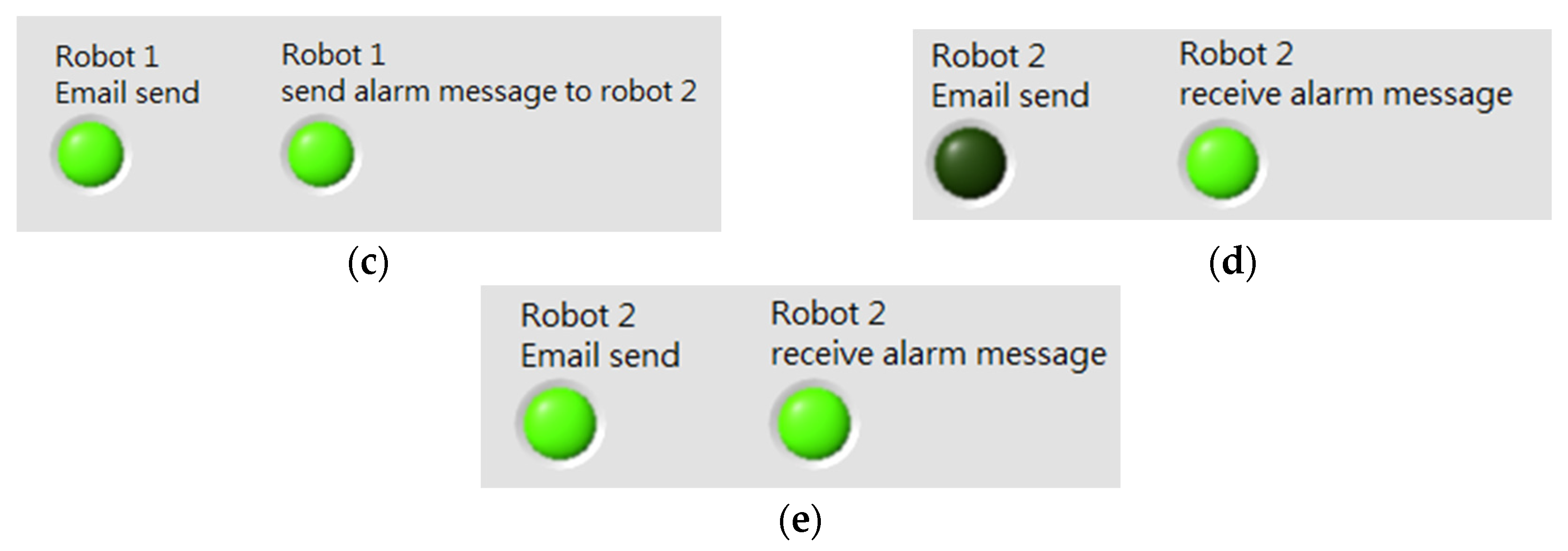
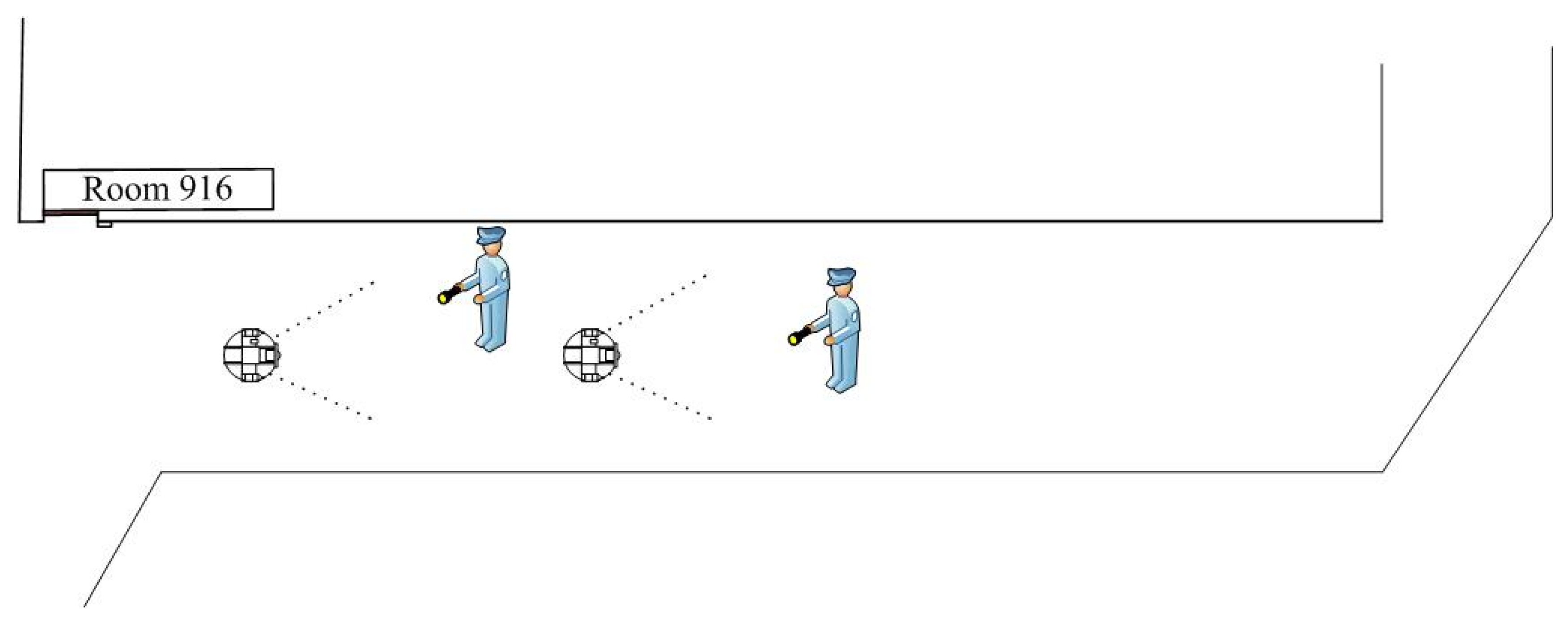
A team with two robots is presented in this subsection. These two robots use the same path planning and tracking control scheme. When the first robot finds the intruder, the robot will send a warning message to the control center in the remote site and to the second robot. The second robot acts as a backup security guard. 
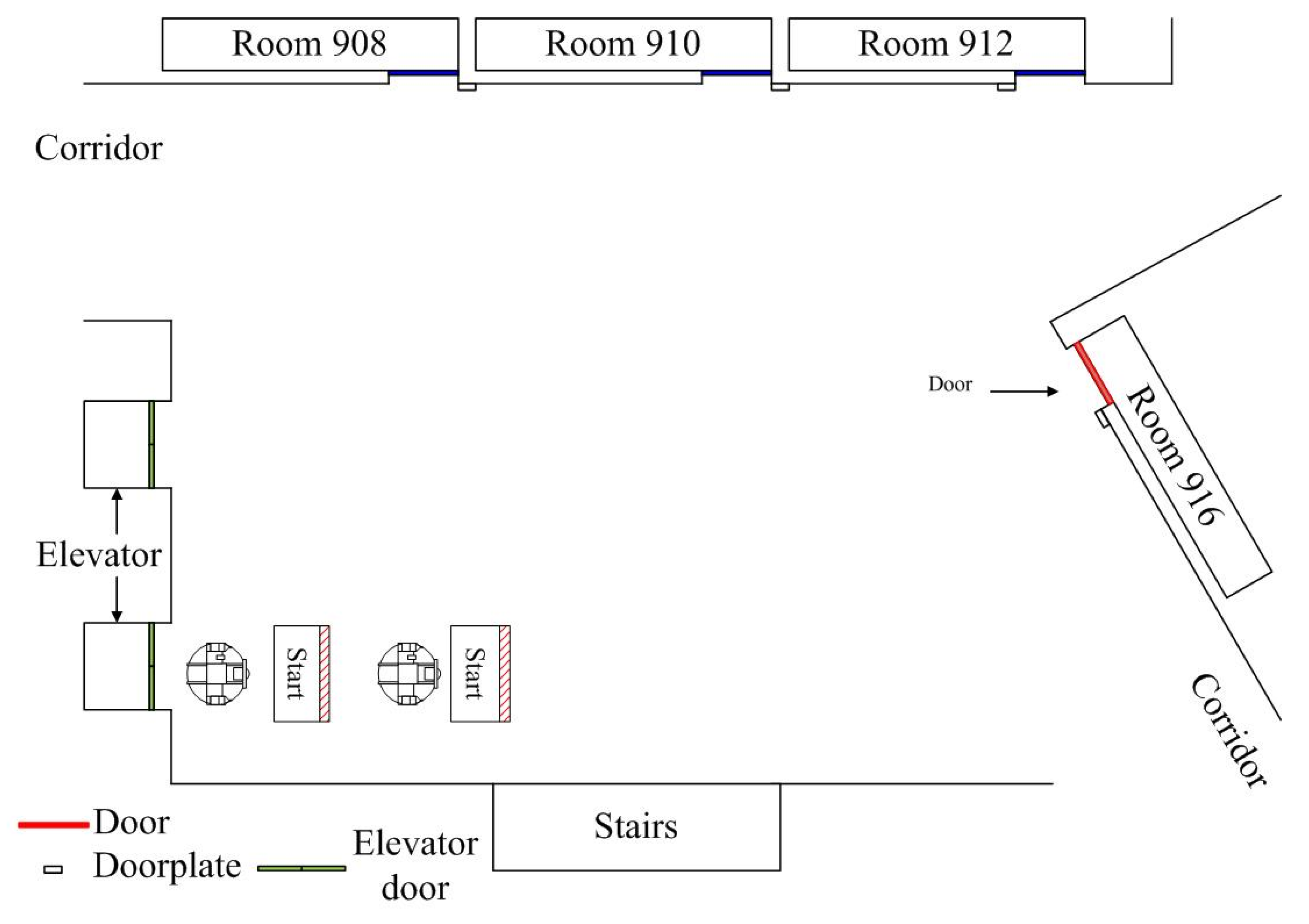
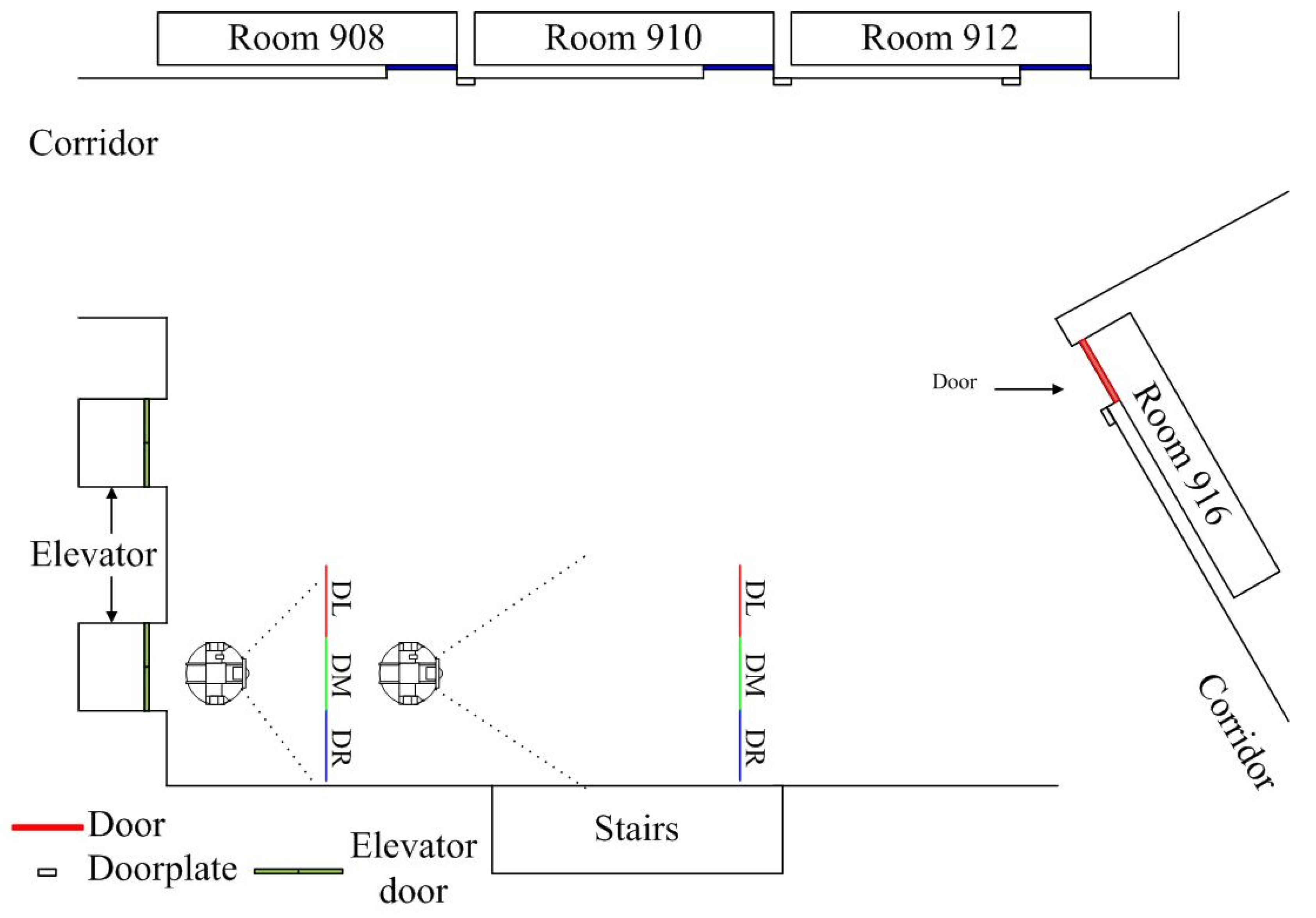
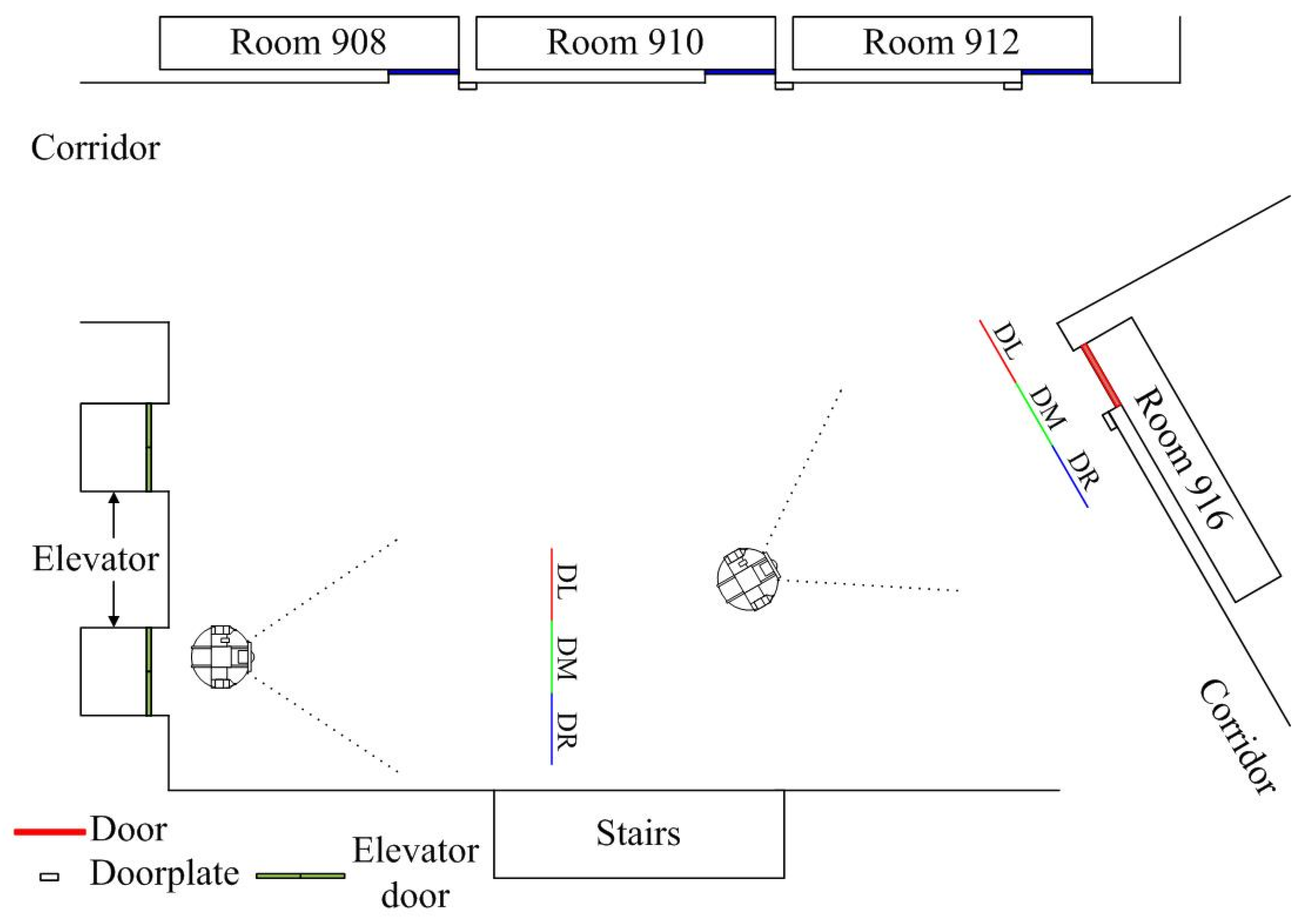
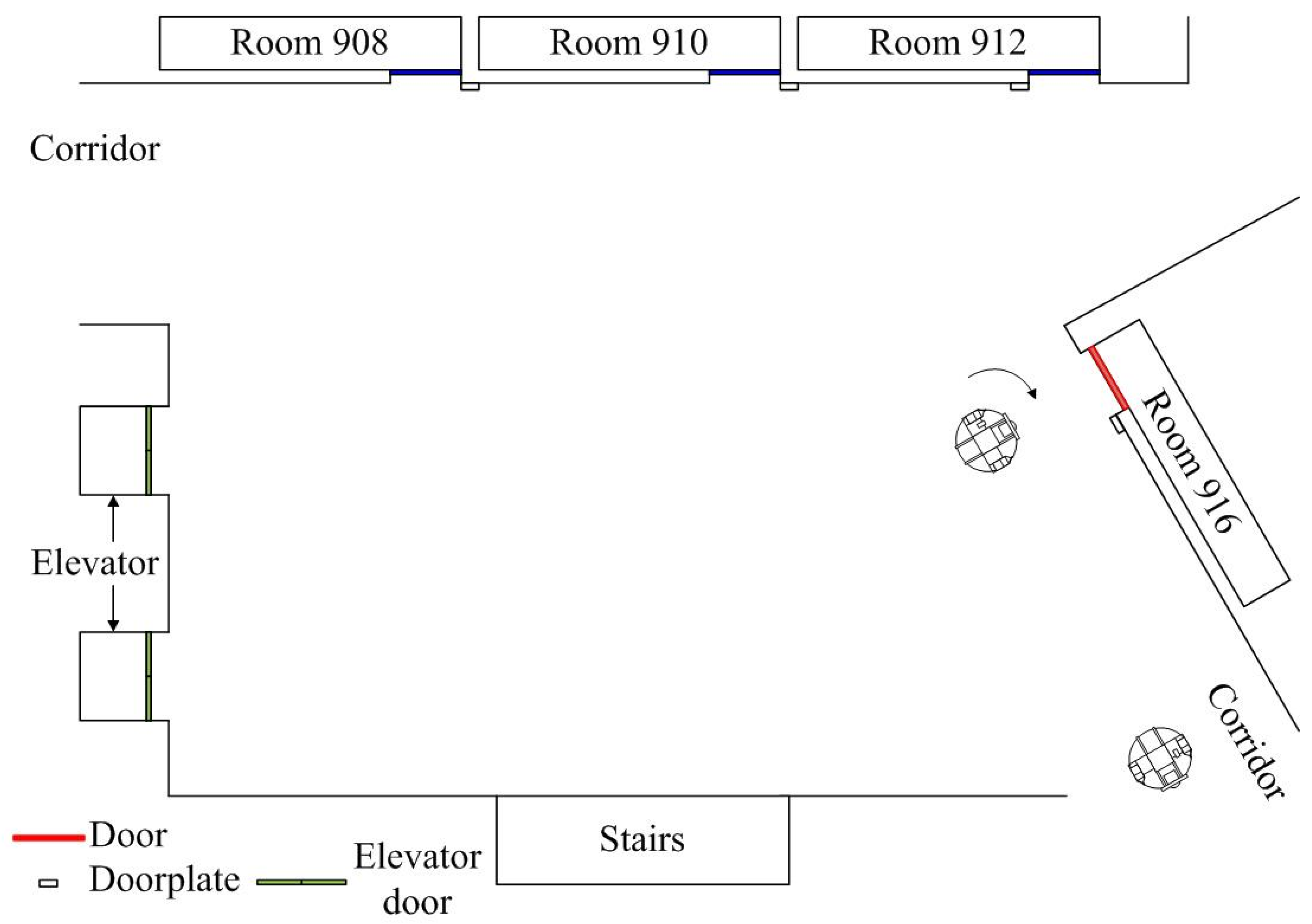
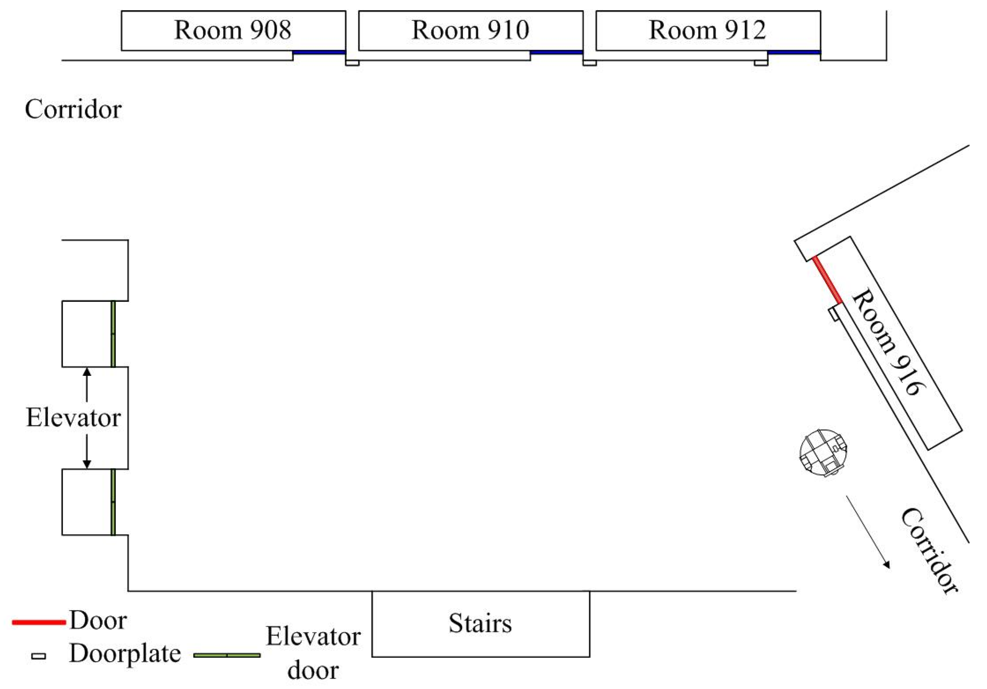
Figure 17 shows the initial setup and experimental environment with the starting location and destination room given. In Figure 18, the target door is not detected at the initial position, so the robot will turn left to face the door. When DL section detects the target, the robot turns left and moves forward. If the DR section detects the target, the robot turns right. When the DM section detects the target, the robot stops turning and moves forward to the door, as shown in Figure 19.
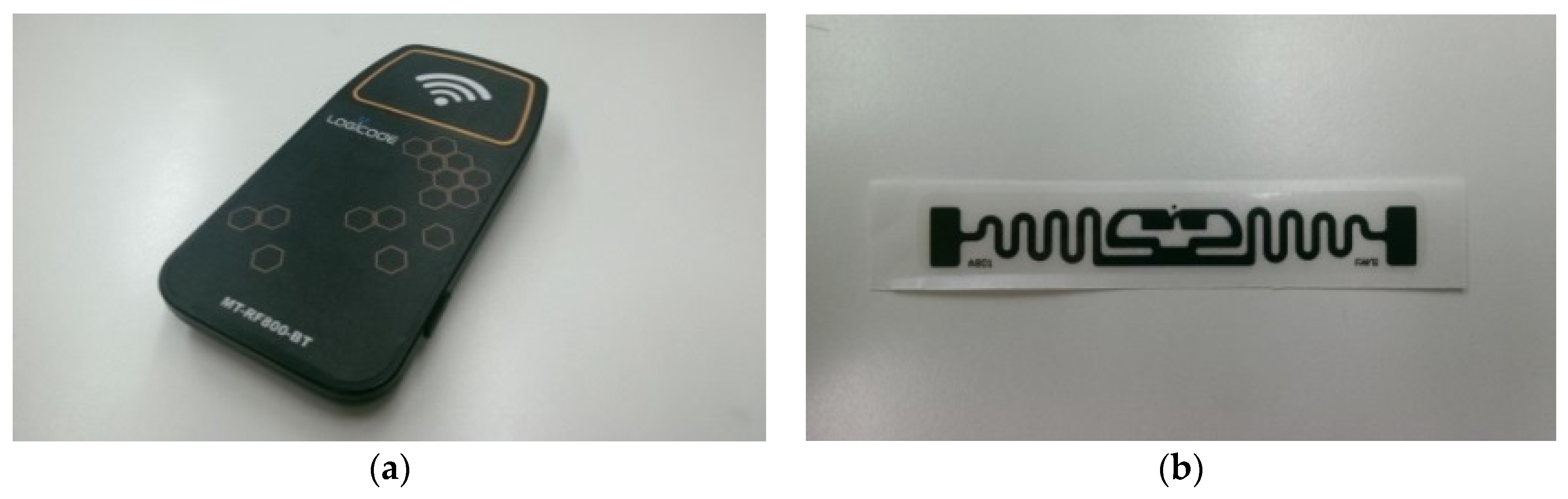
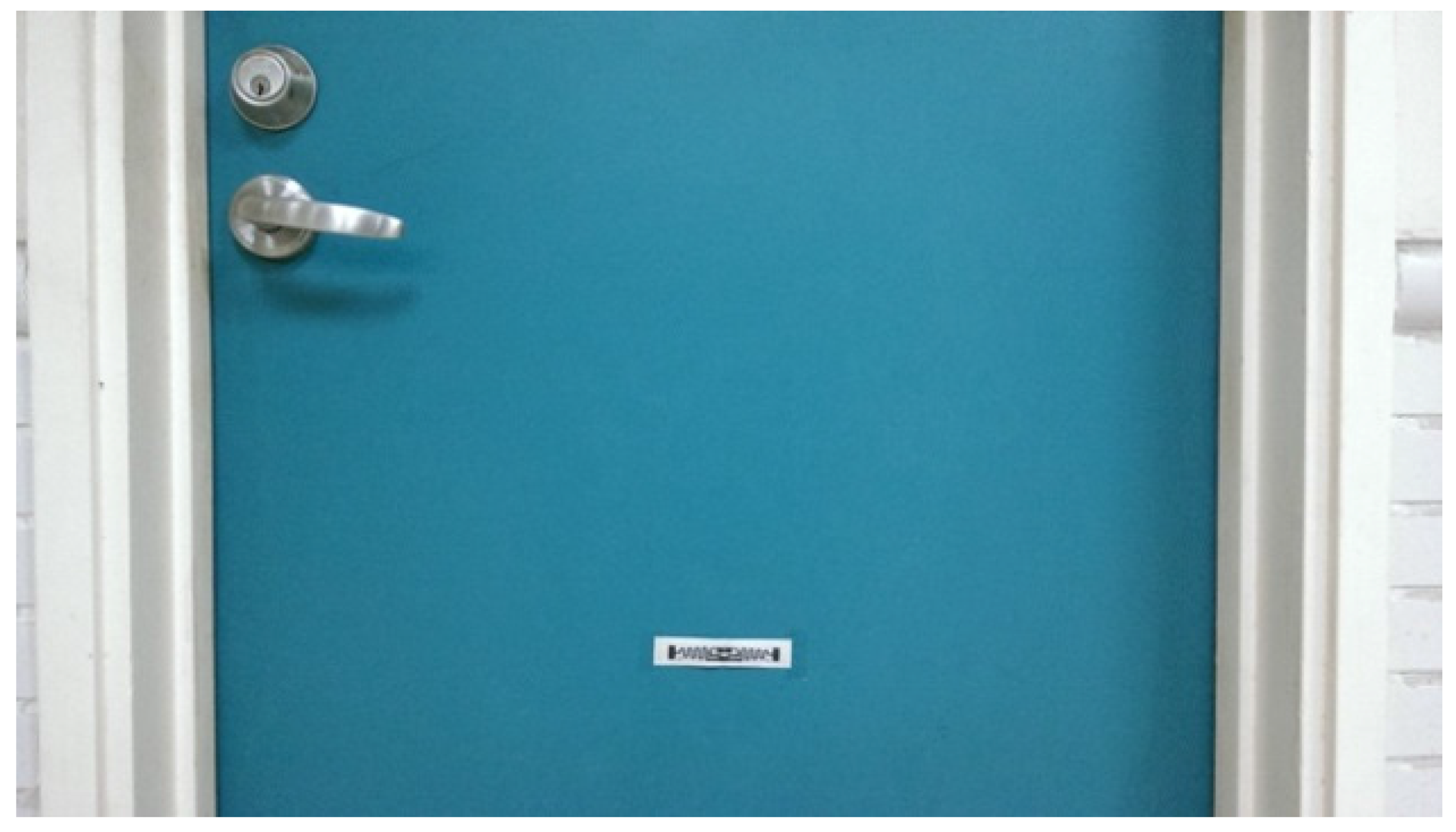
The RFID reader and tag are applied to verify the destination. When omnidirectional WMR approaches a door, the RFID reader will check the tag’s UID. Each RFID tag has its own UID code. Each UID corresponds to a certain room number. A tag posted on the door is shown in Figure 20.
In Figure 21, the RFID reader will read the tag UID to verify the destination at a specified distance. If it is the destination, the robot will move forward to the door. Figure 22 shows that the robot turns right if RFID verifies the correct result. In Figure 23, the webcam and ultrasonic sensor will verify the destination at a specified distance. If it is the destination, then the second robot will move forward to the door. Figure 24 shows the second robot turning right after the webcam verifies the correct result.
In 
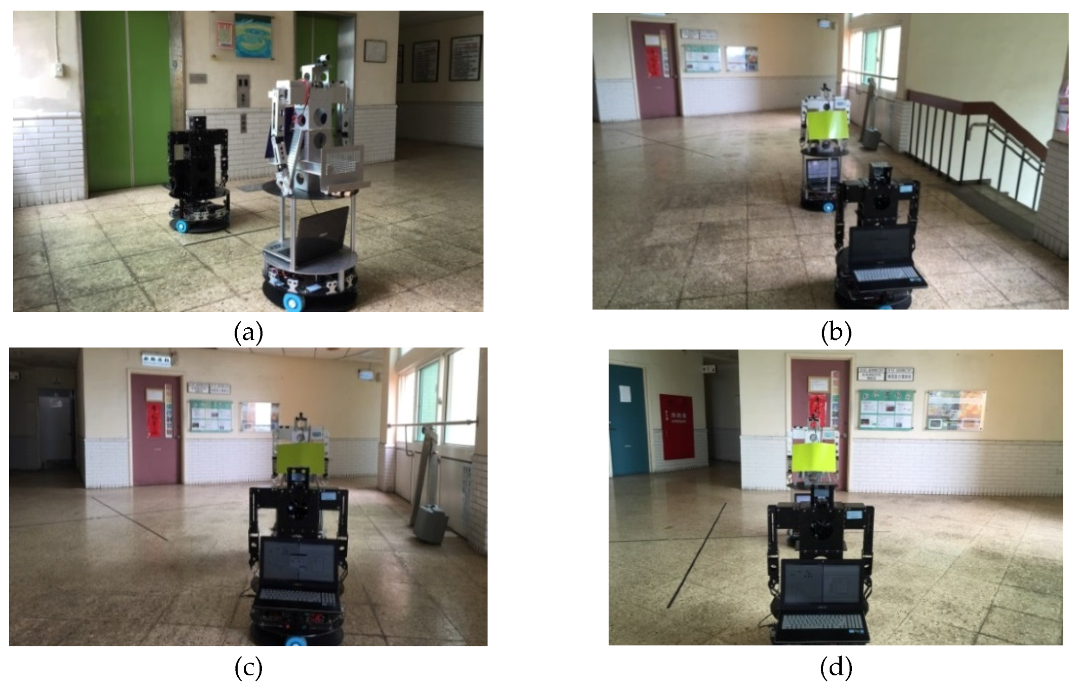
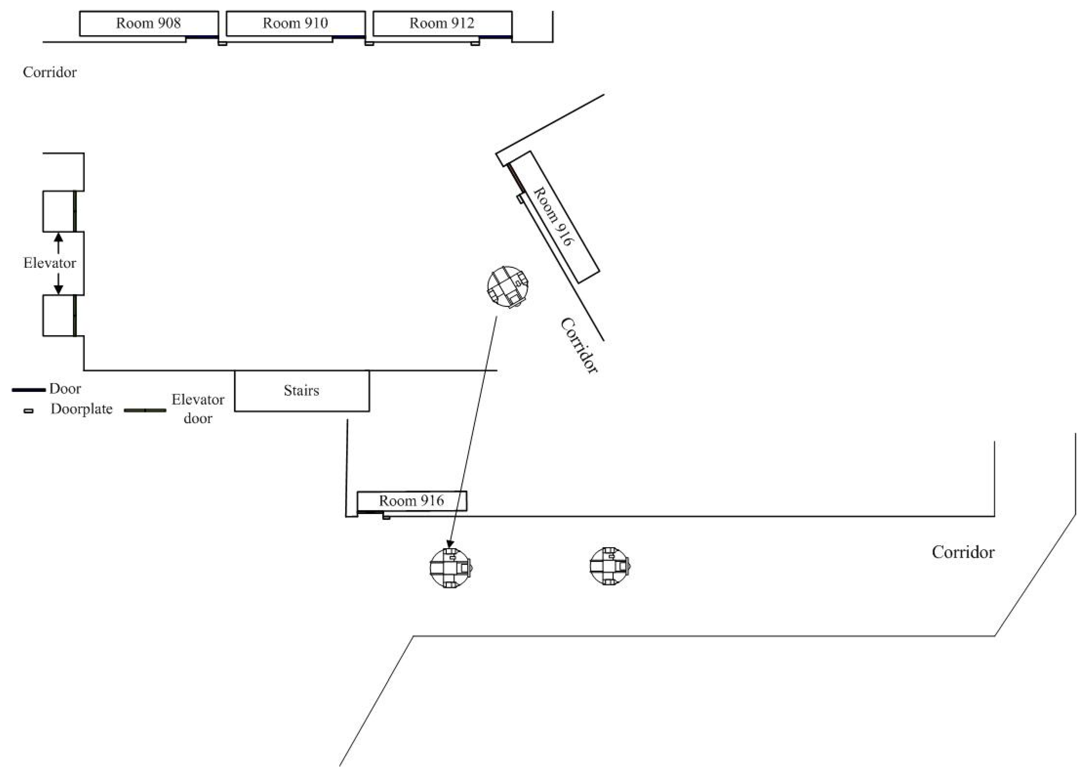
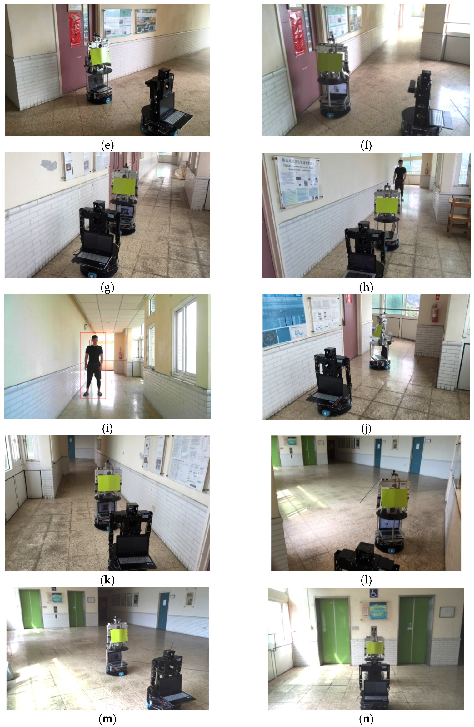
Figure 25, the second robot moves forward along the wall. If the robot is too close to the wall, the WMR will be controlled to move away from the wall. Figure 26 shows a robot in the corridor environment.
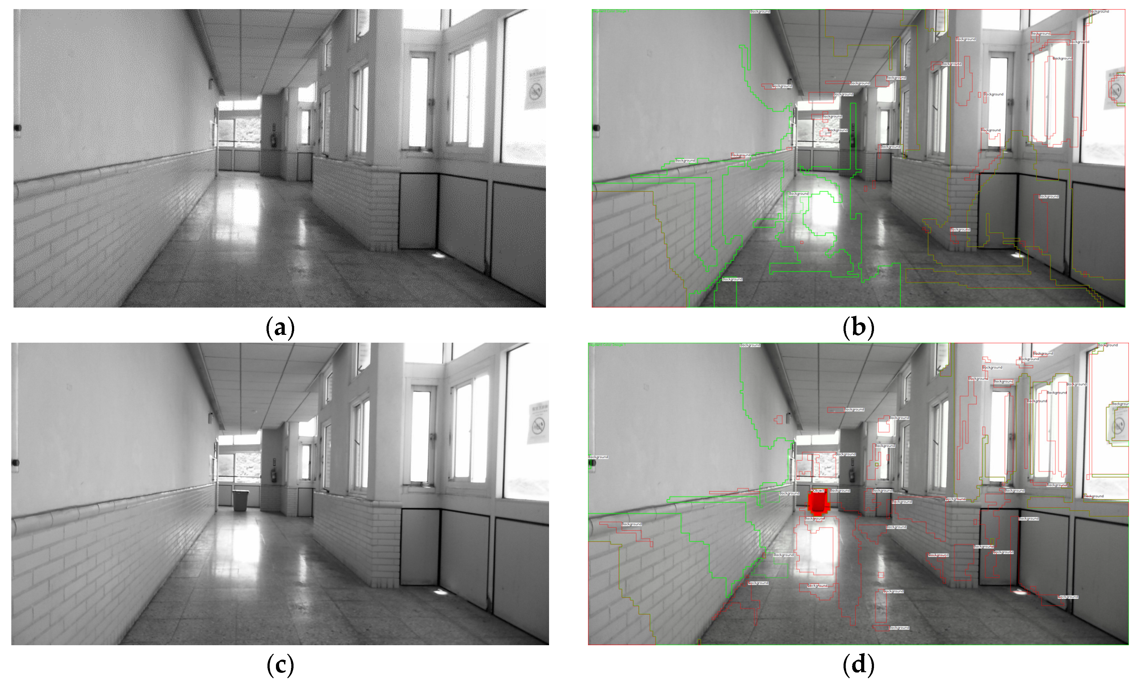
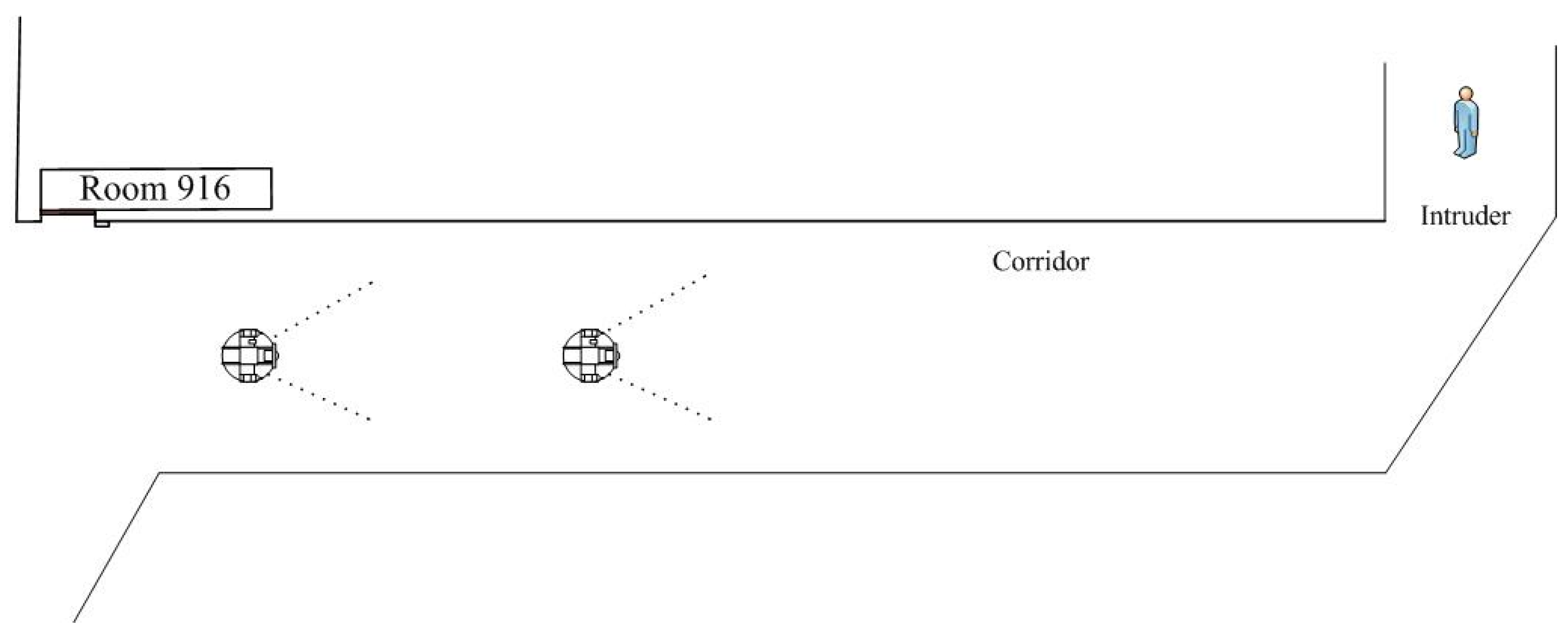
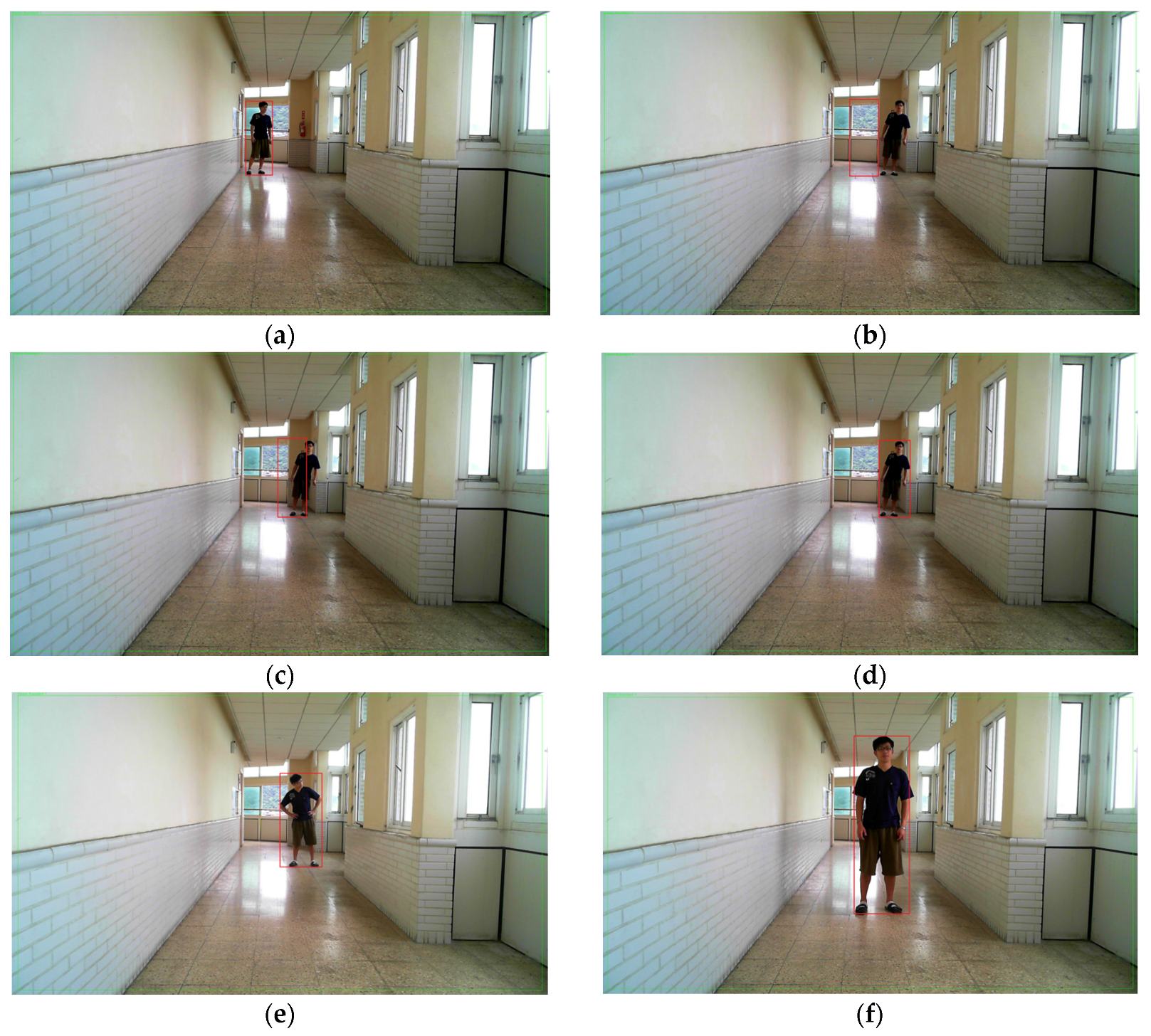
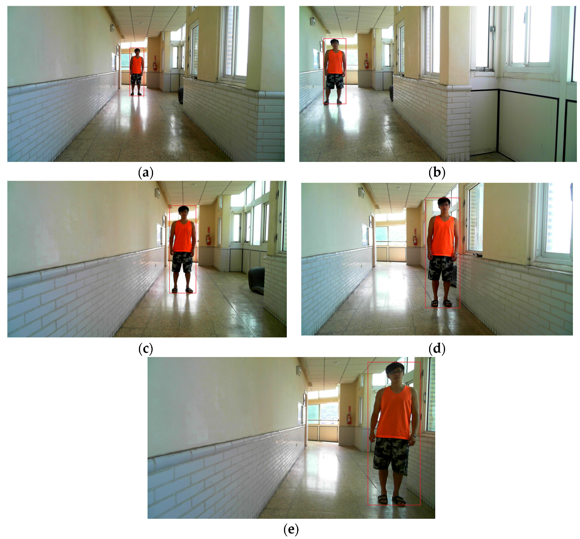
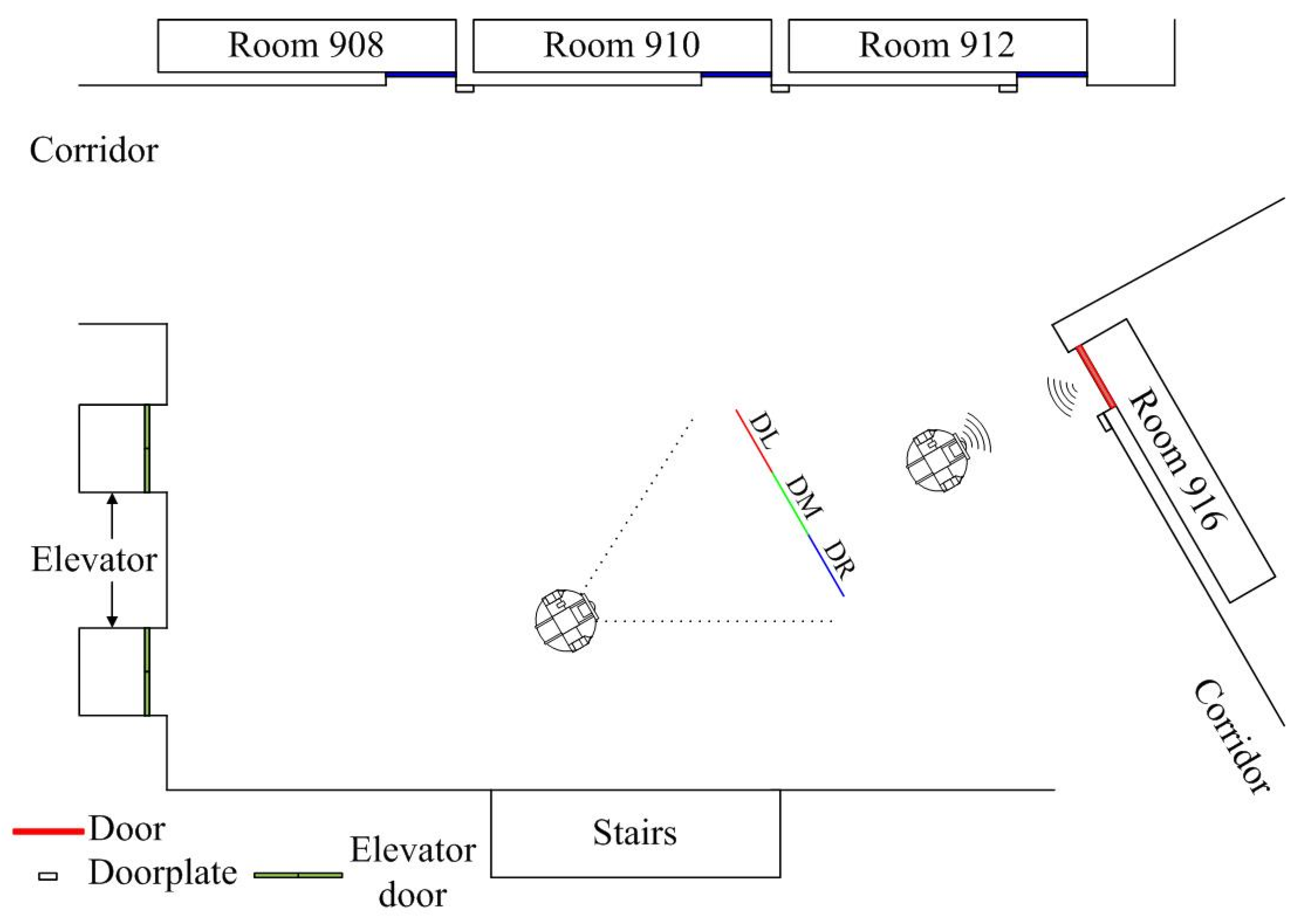
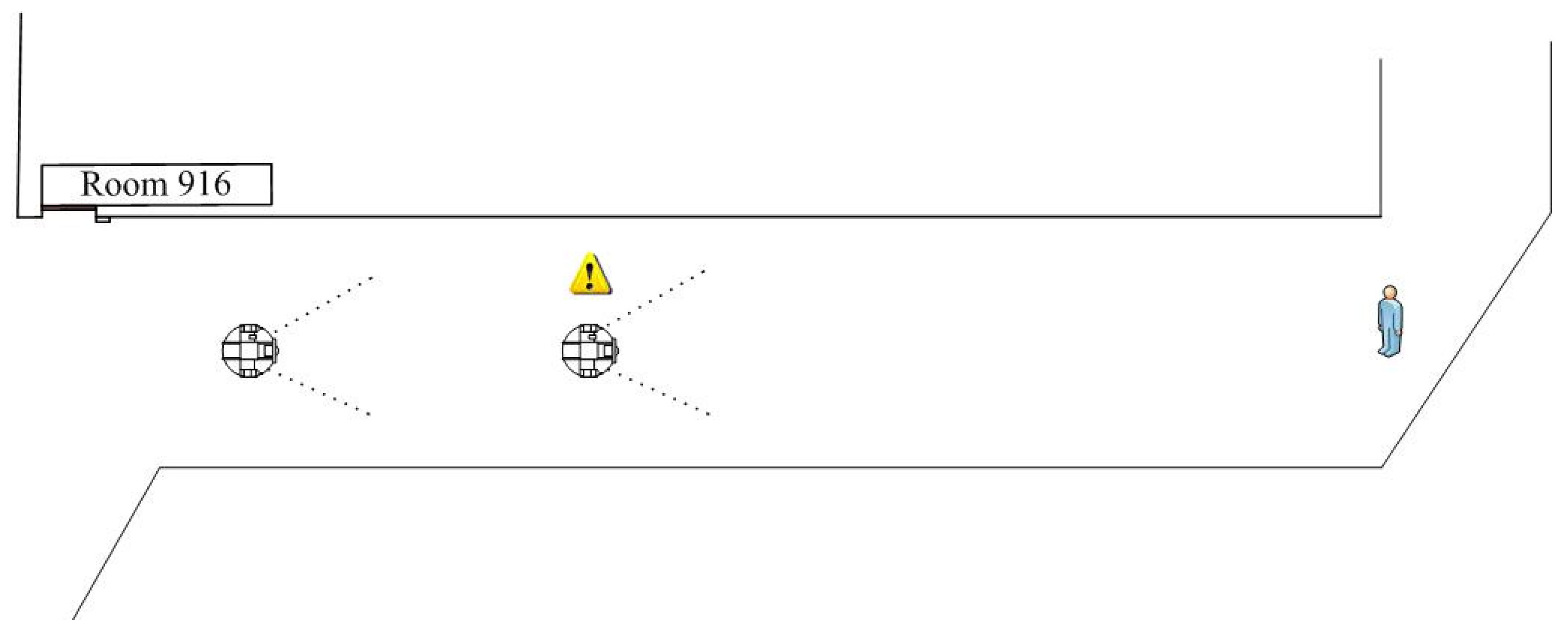
In 
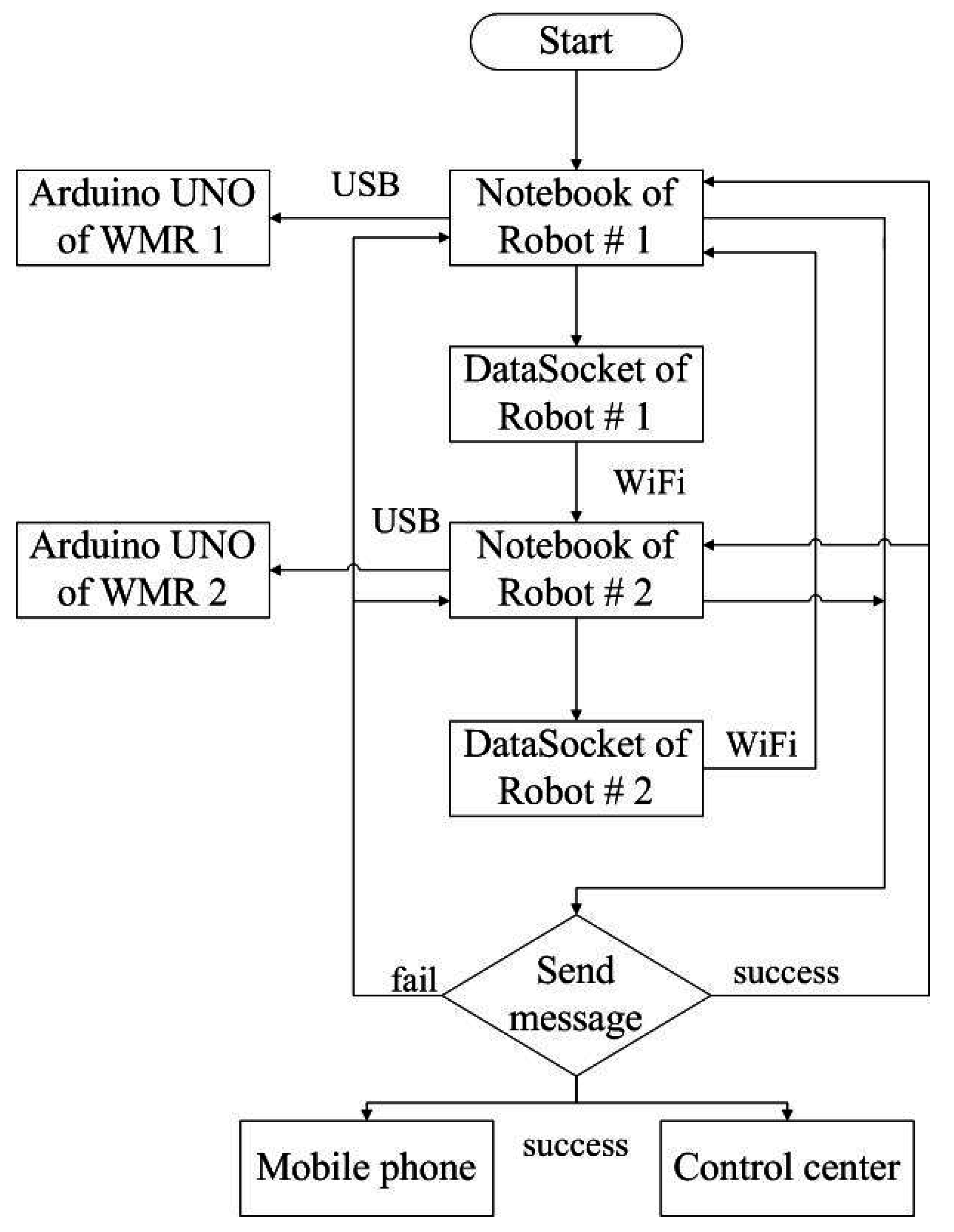
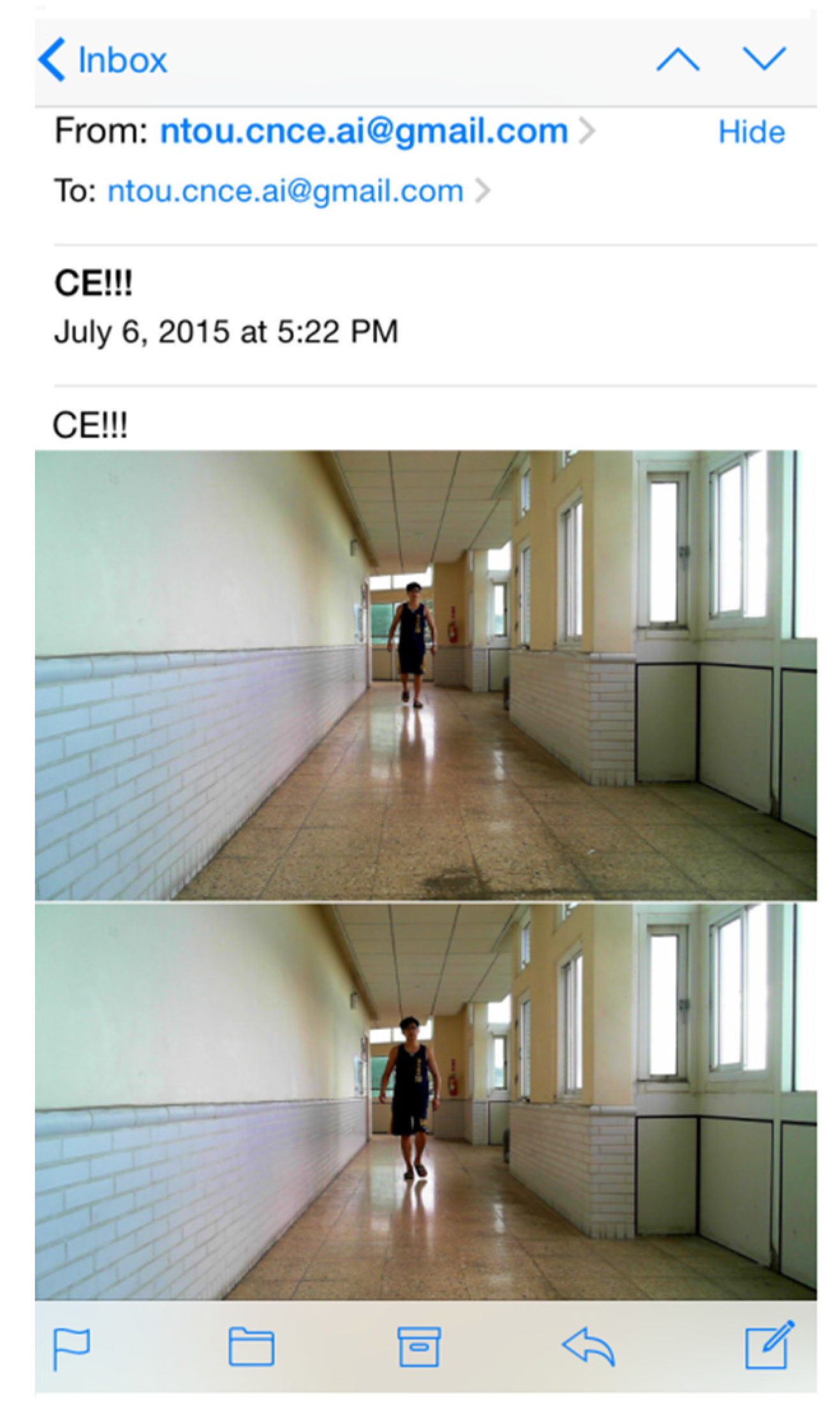
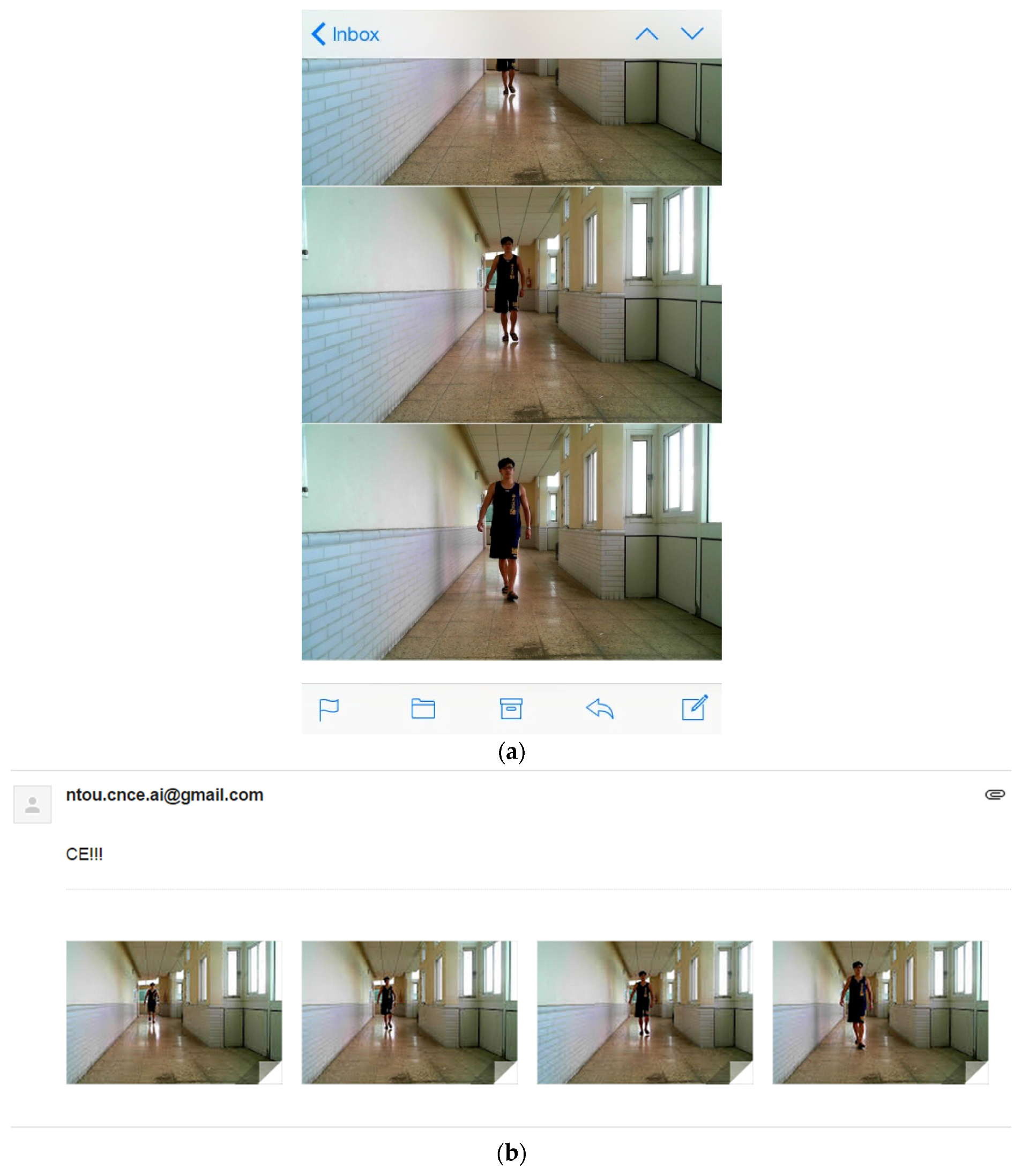
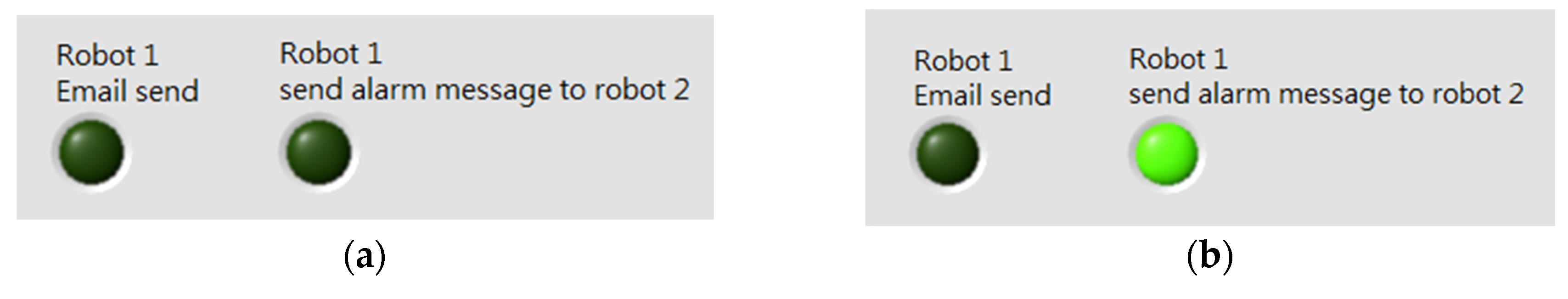
Figure 27, twin robots patrol the corridor and check whether there is an intruder or not. At the other end of the corridor, a man walks in front of the robot. The proposed control scheme can detect environmental colors and find the intruder. When an object appears in the corridor and is intercepted, the image of the object and an alarm signal will be transmitted to the control center and to the second robot via DataSocket server connection IP address and Wi-Fi, as shown in Figure 28 and Figure 29.
In Figure 30, when the control center receives the object detection message and the intruder is confirmed, security guards will move to the scene and check the environmental conditions.

4. Experimental Results

This experiment presents a twin robot indoor patrol. There are six steps in the control sequence: (1) Search for a predefined target and track a designated door; (2) Correct the direction and recognize the first room color; (3) Approach the first room and verify via RFID; (4) Move forward along the wall; (5) Detect an object; (6) Send a message to the control center. Communications of WMR, notebook, control center, and mobile phone are shown in Figure 31.
The proposed control scheme detects environmental colors and finds intruders. When an object appears in the corridor and is intercepted, an image of the object and an alarm signal will be transmitted to the remote control center and to the user’s mobile phone via Wi-Fi, as shown in Figure 32.
When the first robot detects an intruder, an alarm message will be sent to the second robot, as shown in Figure 33. After receiving the alarm message, the second robot starts image processing and sends a captured intruder image to the control center. Data transmitting times of moving objects by different Wi-Fi stations are shown in Table 3.
When the robot finds the destination door, the next step is to recognize the room color. If the room color is verified then the robot moves forward and approaches the door. If the tag UID of the room is reconfirmed, the robot will turn and move along the wall and search for moving objects. Figure 34 shows the dual-robot patrol experimental results.

5. Conclusions

In this study, we propose an intelligent scheme based on fuzzy control, RFID, image processing, fuzzy color classification, and mean shift tracking to control omnidirectional WMR for indoor patrol. In image processing, we integrate the webcam and vision builder to process images and navigate the robot to the destination. A normal image is in RGB color space; however, the composition of three color components and the produced colors are not so intuitive and are susceptible to light interference. So we use HSL color space to solve the problem of light interference. We apply fuzzy color histogram classification to recognize all colors from the pattern image and define the background color. Mean shift tracking can find the highest color density of sample points from the fuzzy color space of the target objects and the objects can be tracked continuously. In the control scheme we used a human–machine interface by LabVIEW 2014 (National Instruments Corporation, Austin, TX, USA) and integrated the MATLAB 2015b (The MathWorks, Inc., Natick, MA, USA) codes and image information by vision builder to control the robot to track the target and reach the destination. RFID reader and tag’s UID can verify the destination to avoid recognition error from image processing. A fuzzy controller can drive the WMR to avoid obstacles easily. This study develops a dual-robot patrol system. The second robot acts as a backup to the first robot while on patrol. Intruder information can be sent to a remote site via the Internet by both robots. The experimental results show that the proposed control scheme can make the dual-robot system perform indoor security service. The proposed system can therefore free up human resources. Further improvements of this study will be to have the robots extinguish unnecessary sidewalk lights and lock unlocked office doors. Although the goal of this study has been achieved, the disadvantage of the proposed system is that the robots can only be applied to indoor service. In the future, GPS will be installed on the robots so that they can also perform outdoor patrols.

Author Contributions

Hardware and software integration was performed by the first author. The corresponding author provided theory analysis and paper writing.

Conflicts of Interest

The authors declare no conflict of interest.

References

  1. Liang, X.; Wang, H.; Chen, W.; Guo, D.; Liu, T. Adaptive Image-Based Trajectory Tracking Control of Wheeled Mobile Robots with an Uncalibrated Fixed Camera. IEEE Trans. Control Syst. Technol. 2015, 23, 2266–2282. [Google Scholar] [CrossRef]
  2. Juang, J.G.; Yu, C.L.; Lin, C.M.; Yeh, R.G.; Rudas, I.J. Real-Time Image Recognition and Path Tracking to Wheeled Mobile Robot for Taking an Elevator. Acta Polytech. Hung. 2013, 10, 5–23. [Google Scholar]
  3. Juang, J.G.; Hsu, K.J.; Lin, C.M. A Wheeled Mobile Robot Path-Tracking System Based on Image Processing and Adaptive CMAC. J. Mar. Sci. Technol. 2014, 22, 331–340. [Google Scholar]
  4. Juang, J.G.; Wang, J.A. Fuzzy Control Simultaneous Localization and Mapping Strategy Based on Iterative Closest Point and k-Dimensional Tree Algorithms. Sens. Mater. 2015, 27, 733–741. [Google Scholar]
  5. Lu, C.Y.; Juang, J.G. Application of Path Planning and Image Searching to Wheeled Mobile Robot Control. In Proceedings of the National Symposium on System Science and Engineering, Taipei, Taiwan, 17–19 July 2015.
  6. Lin, K.H.; Lee, H.S.; Chen, W.T. Implementation of Obstacle Avoidance and ZigBee Control Functions for Omni Directional Mobile Robot. In Proceedings of the IEEE Workshop on Advanced robotics and Its Social Impacts, Taipei, Taiwan, 23–25 August 2008.
  7. Tsai, S.Y. Remote Control for an Omni-Directional Mobile Robot. Master’s Thesis, Department of Mechanical Engineering, Tatung University, Taipei, Taiwan, 2009. [Google Scholar]
  8. Juang, J.G.; Lo, C.W. Computer-Aided Mobile Robot Control Based on Visual and Fuzzy Systems. Adv. Sci. Lett. 2012, 13, 84–89. [Google Scholar] [CrossRef]
  9. Paola, D.D.; Naso, D.; Milella, A.; Cicirelli, G.; Distante, A. Multi-Sensor Surveillance of Indoor Environments byan Autonomous Mobile Robot. In Proceedings of the 15th International Conference on Mechatronics and Machine Vision in Practice, Auckland, New Zealand, 2–4 December 2008.
  10. Zhong, Q.H. Using Omni-Directional Mobile Robot on Map Building Application. Master’s Thesis, Department of Engineering Science, NCKU, Tainan, Taiwan, 2009. [Google Scholar]
  11. Lee, M.F.; Chiu, F.H.; Hung, N.T. An Autonomous Mobile Robot for Indoor Security Patrol. In Proceedings of the International Conference on Fuzzy Theory and Its Applications, Taipei, Taiwan, 6–8 December 2013; pp. 189–194.
  12. Chen, Y.S.; Juang, J.G. Intelligent Obstacle Avoidance Control Strategy for Wheeled Mobile Robot. In Proceedings of the ICCAS-SICE, Fukuoka, Japan, 18–21 August 2009; pp. 3199–3204.
  13. Martinez, J.C.; Sanchez, D.; Hidalgo, J.M.S. A Novel Histogram Definition for Fuzzy Color Spaces. In Proceedings of the 16th IEEE International Conference on Fuzzy Systems, Hong Kong, China, 1–6 June 2008; pp. 2149–2156.
  14. Ju, M.Y.; Ouyang, C.S.; Chang, H.S. Mean Shift Tracking Using Fuzzy Color Histogram. In Proceedings of the International Conference on Machine Learning and Cybernetics, Qingdao, China, 11–14 July 2010; pp. 2904–2908.
  15. Puranik, P.; Bajaj, P.; Abraham, A.; Palsodkar, P.; Deshmukh, A. Human Perception-Based Color Image Segmentation Using Comprehensive Learning Particle Swarm Optimization. In Proceedings of the International Conference on Emerging Trends in Engineering and Technology, Nagpur, India, 6–18 December 2009; pp. 630–635.
  16. Chien, B.C.; Cheng, M.C. A Color Image Segmentation Approach Based on Fuzzy Similarity Measure. In Proceedings of the International Conference on Fuzzy Systems, Honolulu, HI, USA, 12–17 May 2002; pp. 449–454.
  17. Cho, P.C. A Study of Object Tracking in Varying Complex. Backgrounds. Master’s Thesis, Institute of Automation Technology, NTUT, Taipei, Taiwan, 2009. [Google Scholar]
  18. Wong, W.K.; Chew, Z.Y.; Loo, C.K.; Lim, W.S. An Effective Trespasser Detection System Using Thermal Camera. In Proceedings of the International Conference on Computer Research and Development, Kuala Lumpur, Malaysia, 7–10 May 2010; pp. 702–706.
  19. Zalid, L.; Kocmanova, P. Fusion of Thermal Imaging and CCD Camera-based Data for Stereovision Visual Telepresence. In Proceedings of the IEEE International Symposium on Safety, Security, and Rescue Robotics, Linköping, Sweden, 21–26 October 2013.
  20. Kraubling, A.; Schulz, D. Data Fusion for Person Identification in People Tracking. In Proceedings of the International Conference on Information Fusion, Cologne, Germany, 30 June–3 July 2008.
  21. Tzeng, Y.J. Application of Background Subtraction for the Determination of Human Existence in a Working Environment. Master’s Thesis, Institute of Automation Technology, NTUT, Taipei, Taiwan, 2011. [Google Scholar]
  22. Chung, Y.C. A Real-Time Motion Detection and Tracking System in the Dynamic Background. Master’s Thesis, Industrial Technology R & D Master Program on IC Design, NTCU, Taichung, Taiwan, 2007. [Google Scholar]
  23. Machida, E.; Cao, M.; Murao, T.; Hashimoto, H. Human Motion Tracking of Mobile Robot with Kinect 3D Sensor. In Proceedings of the SICE Annual Conference, Akita, Japan, 20–23 August 2012.
  24. Šuligoj, F.; Šekoranja, B.; Švaco, M.; Jerbić, B. Object Tracking with a Multiagent Robot System and a Stereo Vision Camera. Procedia Eng. 2014, 69, 968–973. [Google Scholar] [CrossRef]
  25. Chen, H.S.; Juang, J.G. Path Planning and Parking Control of a Wheeled Mobile Robot. In Proceedings of the National Symposium on System Science and Engineering, ILan, Taiwan, 6–7 June 2008.
  26. Lu, K.; Ni, J.; Wang, L.W. Capsule Color Inspection on Uneven Illumination Images. In Proceedings of the International Congress on Image and Signal Processing, Hangzhou, China, 16–18 December 2013.
  27. Mente, R.; Dhandra, B.V.; Mukarambi, G. Color Image Segmentation and Recognition based on Shape and Color Features. Int. J. Comput. Sci. Eng. 2014, 3, 51–56. [Google Scholar]
  28. Cheng, Y. Mean Shift, Mode Seeking, and Clustering. IEEE Trans. Pattern Anal. Mach. Intell. 1995, 17, 790–799. [Google Scholar] [CrossRef]
  29. Lee, S.H.; Lee, J. Image Segmentation Based on Fuzzy Flood Fill Mean Shift Algorithm. In Proceedings of the Annual Meeting of the North American Fuzzy Information Processing Society, Toronto, ON, Canada, 12–14 July 2010.
  30. Ukrainitz, Y.; Sarel, B. Mean Shift Theory and Applications. Available online: http://www.wisdom.weizmann.ac.il/~vision/courses/2004_2/files/mean_shift/mean_shift.ppt (accessed on 3 January 2016).
Figure 1. (a) RGB image and (b) hue, saturation, and lightness (HSL) image.
Applsci 06 00349 g001
Figure 2. Blocks in different colors.
Applsci 06 00349 g002
Figure 3. Fuzzy sets of color classification system.
Applsci 06 00349 g003
Figure 4. Fuzzy color classifications.
Applsci 06 00349 g004
Figure 5. Classifications of the background environment and object: (a) background environment; (b) training background color distribution; (c) add object in background environment; (d) classifications of the background environment and object.
Applsci 06 00349 g005
Figure 6. Steps for finding the highest density of color: (a) Search high color density; (b) search high color density again; (c) reach center of mass.
Applsci 06 00349 g006
Figure 7. Steps for mean shift tracking process against a static background: (a) Find the object; (b) the object moves to the right side; (c) search high color density; (d) catch the object; (e) the object moves forward; (f) keep tracking the object.
Applsci 06 00349 g007
Figure 8. Steps for tracking a moving object against a dynamic background: (a) Find the object; (b) scroll right; (c) the object moves forward; (d) the object moves; (e) keep tracking the object.
Applsci 06 00349 g008
Figure 9. Omnidirectional WMR.
Applsci 06 00349 g009
Figure 10. (a) MX—64; (b) MX—28.
Applsci 06 00349 g010
Figure 11. Omnidirectional WMR coordinate system.
Applsci 06 00349 g011
Figure 12. Simplified kinematic model of omnidirectional WMR.
Applsci 06 00349 g012
Figure 13. Ultrasonic sensors.
Applsci 06 00349 g013
Figure 14. Fuzzy sets.
Applsci 06 00349 g014
Figure 15. Flowchart of control sequence.
Applsci 06 00349 g015
Figure 16. (a) Ultra High Frequency (UHF) RFID reader MT-RF800-BT and (b) UHF tag.
Applsci 06 00349 g016
Figure 17. Initial setup and experimental environment.
Applsci 06 00349 g017
Figure 18. Target is not detected, thus the robot turns left to find the room color.
Applsci 06 00349 g018
Figure 19. The robot turns left; the DM detects the target; and the robot moves forward to the predefined door.
Applsci 06 00349 g019
Figure 20. Tag posted on the door.
Applsci 06 00349 g020
Figure 21. RFID verifies the destination at a specified distance.
Applsci 06 00349 g021
Figure 22. If the verification result is positive, the robot turns right.
Applsci 06 00349 g022
Figure 23. An ultrasonic sensor measures the distance between the robot and the door.
Applsci 06 00349 g023
Figure 24. If the verification result is positive, the second robot turns right.
Applsci 06 00349 g024
Figure 25. The second robot moves forward along the wall.
Applsci 06 00349 g025
Figure 26. The corridor environment diagram.
Applsci 06 00349 g026
Figure 27. Twin robots on an indoor patrol.
Applsci 06 00349 g027
Figure 28. The first robot finds an intruder.
Applsci 06 00349 g028
Figure 29. The first robot sends an alarm message to the remote control center and to the second robot.
Applsci 06 00349 g029
Figure 30. Security guards inspect the scene directly.
Applsci 06 00349 g030
Figure 31. Communication sequence.
Applsci 06 00349 g031
Figure 32. The first robot sends instant images to the control center and to the user’s smartphone. (a) Smartphone receives notification message about the intruder; (b) remote control center receives notification message about the intruder.
Applsci 06 00349 g032aApplsci 06 00349 g032b
Figure 33. First robot sends alarm message to the second robot. (a) Robot 1 initial signal indicators are off; (b) Robot 1 sends signal to Robot 2; (c) Robot 1 sends e-mail to control center; (d) Robot 2 receives alarm message; (e) Robot 2 sends e-mail to control center.
Applsci 06 00349 g033aApplsci 06 00349 g033b
Figure 34. Experimental results of dual-robot patrol. (a) Starting position; (b) detecting doors; (c) moving forward to destination door; (d) when the robot approaches to the door, it will correct its position to aim at the room plate and door; (e) if it is the correct destination, the robot will approach the door and use RFID to verify the tag UID; (f) the robot turns right after verification is confirmed; (g) shifting path; (h) find moving object; (i) mean shift tracking and send message to the control center; (j) come to the end and rotate; (k) shifting path; (l) find the starting point of the elevator; (m) go straight to the elevator; (n) arrive back at the starting position.
Applsci 06 00349 g034aApplsci 06 00349 g034b
Table 1. The known pattern color values.
ColorHue ValueSaturation ValueLightness Value
Orange17185155
Yellow43255226
Green52120192
Blue128196192
Purple213116110
Table 2. Object HSL color values.
ColorHueSaturation ValueLightness Value
Red (object)25418492
Table 3. Data transmission times of moving objects.
Type of Wi-Fi StationImage Upload (s)Message Upload (s)Data Transmit Rate (Mbps)
Mobile phone3190
Lab Router10125
Hallway station15210

