
Co-Firing of Fast Pyrolysis Bio-Oil and Heavy Fuel Oil in a 300-kWth Furnace


Abstract
:
1. Introduction
2. Experimental
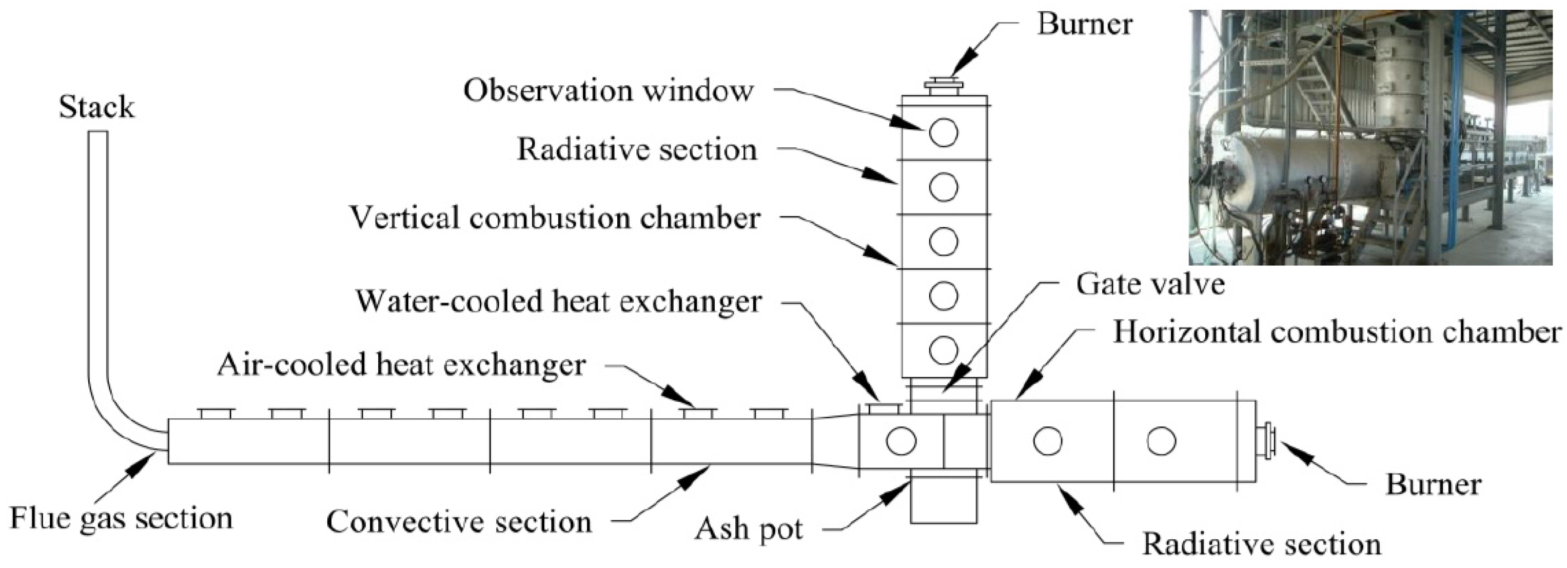
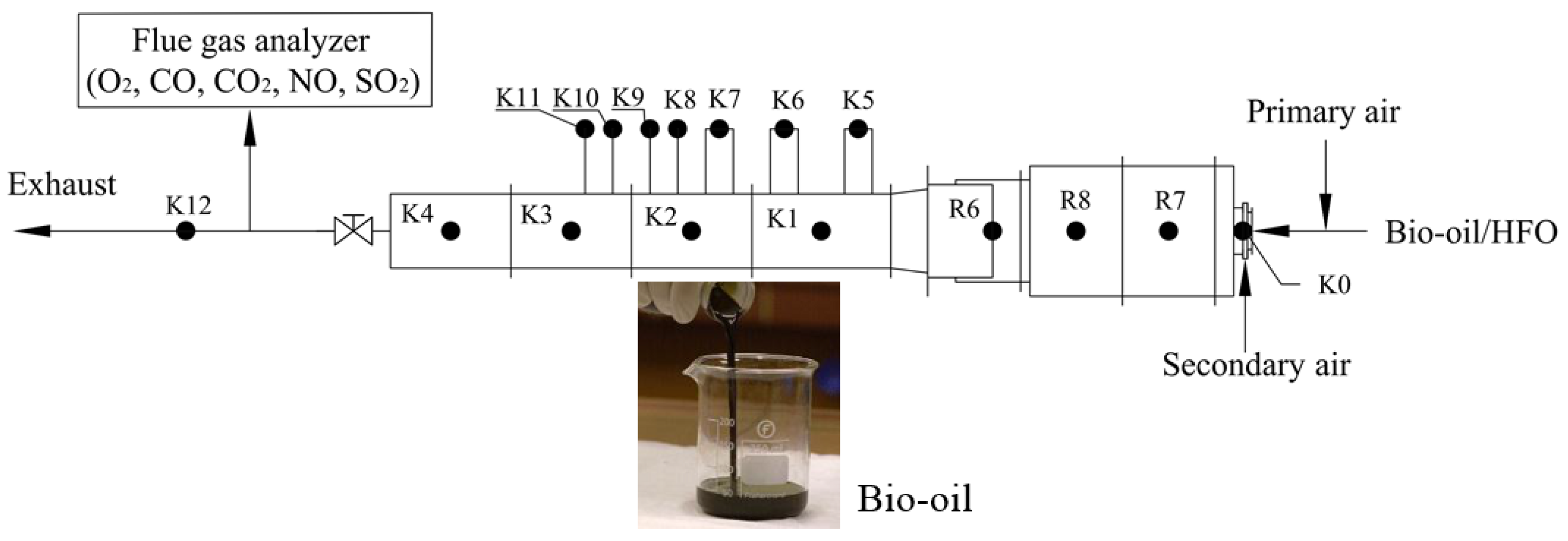
2.1. Furnace
2.2. Experimental Procedures
2.3. Furnace Preheating Process
3. Results and Discussion
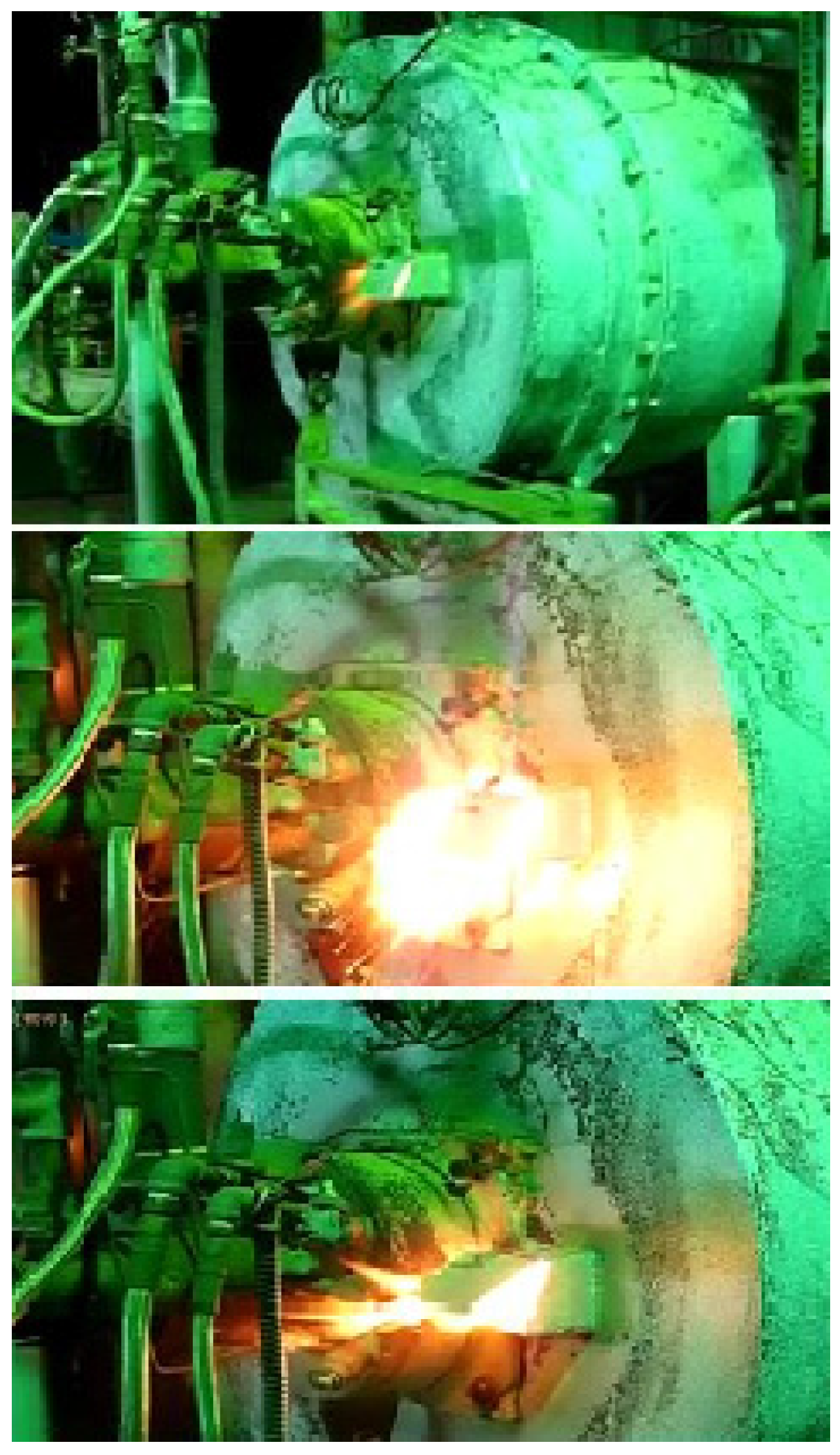
3.1. Combustion Tuning
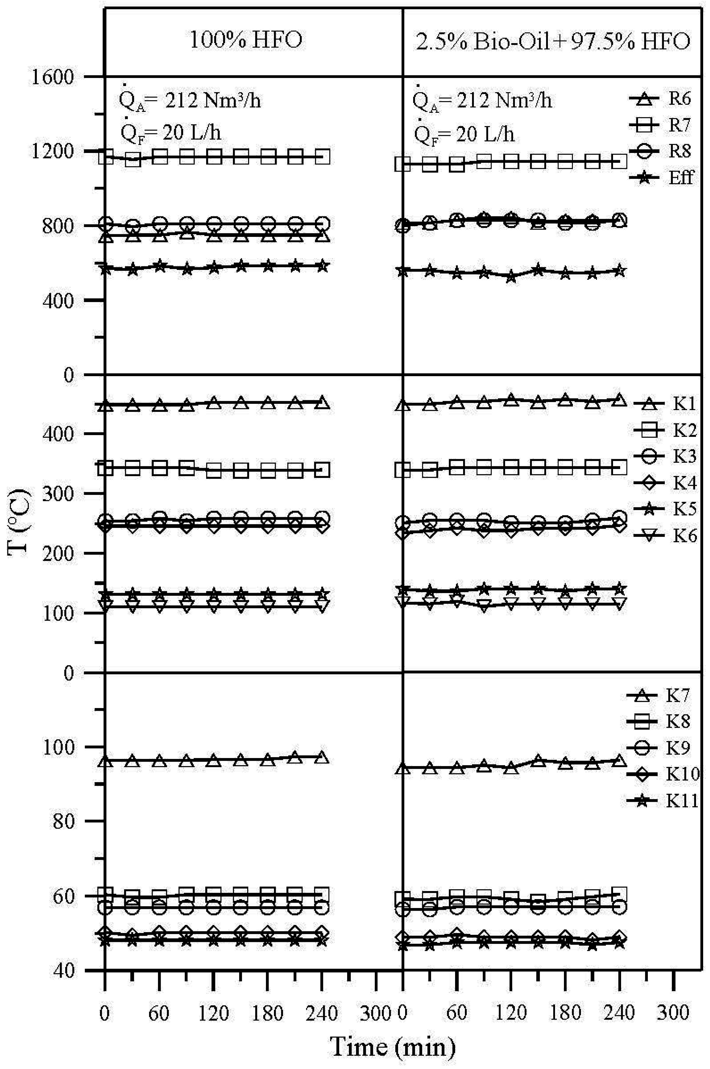
3.2. Temperature Distribution
3.3. Emissions
4. Conclusions
- (1)
- At fixed fuel and air flow rates, burning the emulsion of 2.5% bio-oil + 97.5% HFO resulted in a slightly lower temperature in the combustion chamber than burning pure HFO, since the pyrolysis bio-oil has a low calorific value and a high water content of as much as 27%.
- (2)
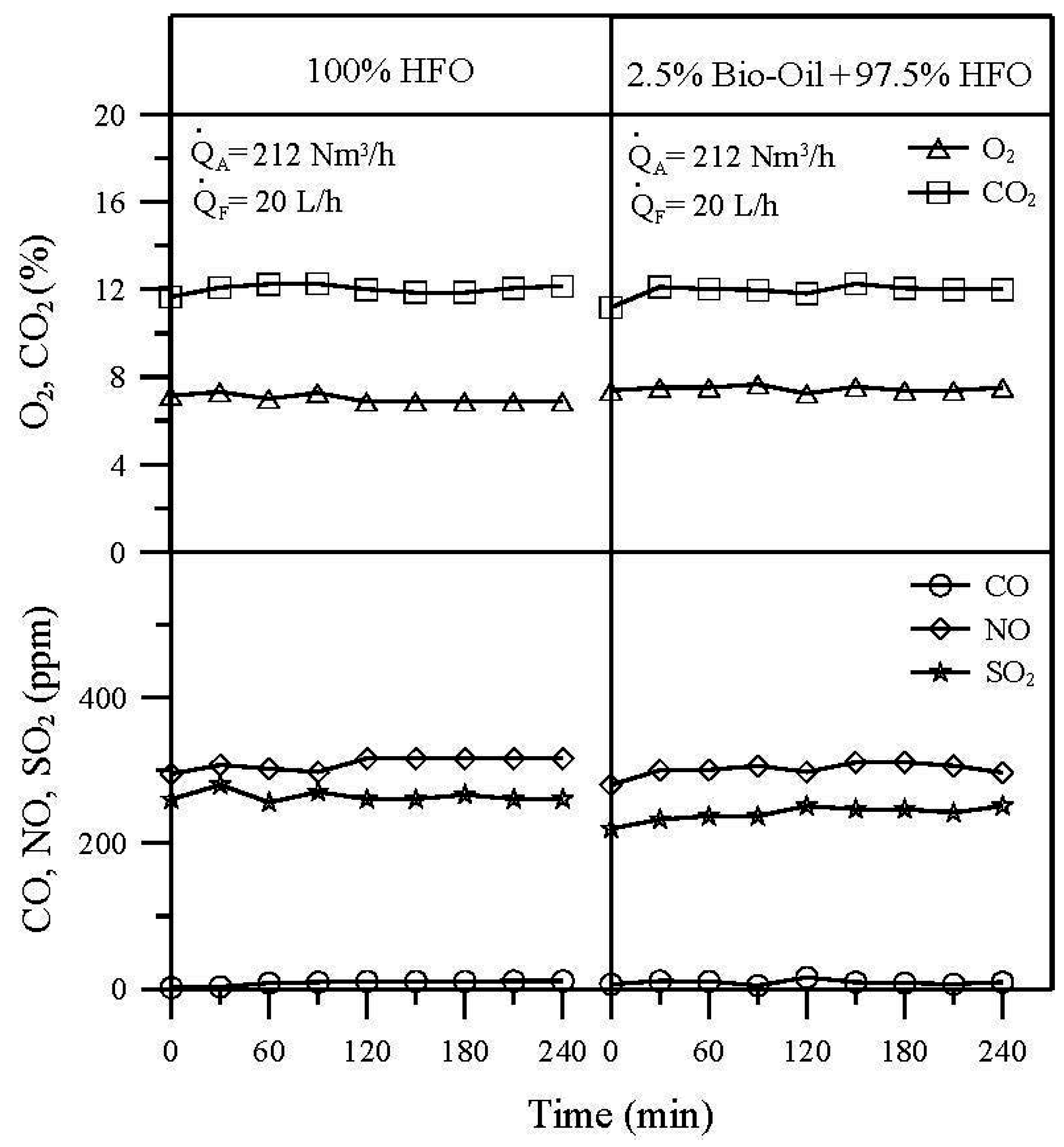
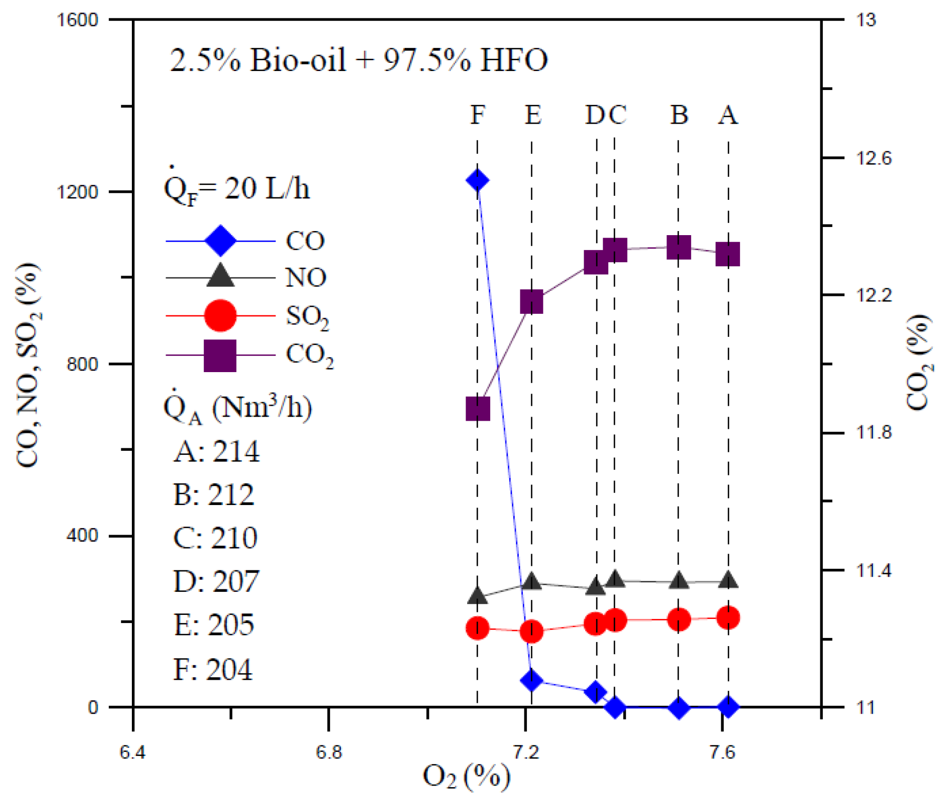
- O2 and CO2 concentrations in flue gas for burning the blend of 2.5% bio-oil + 97.5% HFO and pure HFO were nearly the same. Additionally, the CO concentrations in these two burning conditions are close to 0 ppm because of the low excess oxygen operating conditions.
- (3)
- Compared with burning pure HFO, an NO emission reduction of around 2.6% was obtained for burning the emulsion of 2.5% bio-oil + 97.5% HFO.
- (4)
- SO2 emission for burning the emulsion of 2.5% bio-oil + 97.5% HFO was slightly lower than that for burning pure HFO. An SO2 emission reduction of around 7.9% was obtained.
Acknowledgments
Author Contributions
Conflicts of Interest
References
- Bridgwater, A.V.; Meier, D.; Radlein, D. An overview of fast pyrolysis of biomass. Org. Geochem. 1999, 30, 1479–1493. [Google Scholar] [CrossRef]
- Goyal, H.B.; Seal, D.; Saxena, R.C. Bio-fuels from thermochemical conversion of renewable resources: A review. Renew. Sustain. Energy Rev. 2008, 12, 504–517. [Google Scholar] [CrossRef]
- Chiaramonti, D.; Oasmaa, A.; Solantausta, Y. Power generation using fast pyrolysis liquids from biomass. Renew. Sustain. Energy Rev. 2007, 11, 1056–1086. [Google Scholar] [CrossRef]
- Brammer, J.G.; Lauer, M.; Bridgwater, A.V. Opportunities for biomass-derived “bio-oil” in European heat and power markets. Energy Policy 2006, 34, 2871–2880. [Google Scholar] [CrossRef]
- Asadullah, M.; Rahman, M.A.; Ali, M.M.; Motin, M.A.; Sultan, M.B.; Alam, M.R.; Rahman, M.S. Jute stick pyrolysis for bio-oil production in fluidized bed reactor. Bioresour. Technol. 2008, 99, 44–50. [Google Scholar] [CrossRef] [PubMed]
- Zheng, J.L.; Kong, Y.P. Spray combustion properties of fast pyrolysis bio-oil produced from rice husk. Energy Convers. Manag. 2010, 51, 182–188. [Google Scholar] [CrossRef]
- Rizal, F.M.; Lin, T.H.; Yang, T.Y.; Wan, H.P.; Lee, H.T. Vaporization characteristics of a single drop of diesel-biofuel mixtures. In Proceedings of the Annual Conference on Liquid Atomization and Spray Systems—Asia, Pingtung, Taiwan, 20–21 October 2011; pp. 265–273.
- Balat, M.; Balat, M.; Kirtay, E.; Balat, H. Main routes for the thermo-conversion of biomass into fuels and chemicals. Part 1: Pyrolysis systems. Energy Convers. Manag. 2009, 50, 182–188. [Google Scholar] [CrossRef]
- Vamvuka, D. Bio-oil, solid and gaseous biofuels from biomass pyrolysis processes—An overview. Int. J. Energy Res. 2011, 35, 835–862. [Google Scholar] [CrossRef]
- Brown, T.R.; Wright, M.M.; Brown, R.C. Estimating profitability of two biochar production scenarios: Slow pyrolysis vs. fast pyrolysis. Biofuels Bioprod. Biorefin. 2011, 5, 54–68. [Google Scholar] [CrossRef]
- Kerolli-Mustafa, M.; Lajqi-Makolli, V.; Berisha-Shala, S.; Latifa, L.; Malollari, I.; Morina, I. Biomass and biofuel overview. A global sustainability challenge. J. Environ. Prot. Ecol. 2015, 16, 222–232. [Google Scholar]
- Jahirul, M.I.; Rasul, M.G.; Chowdhury, A.A.; Ashwath, N. Biofuels production through biomass pyrolysis—A technological review. Energies 2012, 5, 4952–5001. [Google Scholar] [CrossRef]
- Bradley, D. European Market Study for BioOil (Pyrolysis Oil). Available online: http://www.unece.lsu.edu/biofuels/documents/2007July/SRN_009.pdf (accessed on 15 December 2006).
- Bari, S. Performance, combustion and emission tests of a metro-bus running on biodiesel-ULSD blended (B20) fuel. Appl. Energy 2014, 124, 35–43. [Google Scholar] [CrossRef]
- Ge, J.C.; Kim, M.S.; Yoon, S.K.; Choi, N.J. Effects of pilot injection timing and EGR on combustion, performance and exhaust emissions in a common rail diesel engine fueled with a canola oil biodiesel-diesel blend. Energies 2015, 8, 7312–7325. [Google Scholar] [CrossRef]
- Sturzl, R. The Commercial Co-Firing of RTP Bio-Oil at the Manitowoc Public Utilities Power Generation Station; Manitowoc Public Utilities: Manitowoc, WI, USA, 1997. [Google Scholar]
- Wagenaar, B.M.; Venderbosch, R.H.; Prins, W.; Penninks, F.W.M. Bio-oil as a coal substitute in a 600 MWe Power Station. In Proceedings of the 12th European Conference and Technology Exhibition on Biomass for Energy, Industry and Climate Protection, Amsterdam, The Netherlands, 17–21 June 2002; pp. 17–21.
- Wagenaar, B.M.; Gansekoele, E.; Florijn, J.; Venderbosch, R.H.; Penninks, F.W.M.; Stellingwerf, A. Bio-Oil as Natural Gas Substitute in a 350 MW Power Station; BTG Biomass Technology Group BV and Electrabel Nederland NV: Enschede, The Netherlands, 2004. [Google Scholar]
- Czernik, S.; Bridgwater, A.V. Overview of applications of biomass fast pyrolysis oil. Energy Fuels 2004, 18, 590–598. [Google Scholar] [CrossRef]
- Hou, S.S.; Rizal, F.M.; Lin, T.H.; Yang, T.Y.; Wan, H.P. Microexplosion and ignition of droplets of fuel oil/bio-oil (lauan wood) blends. Fuel 2013, 113, 31–42. [Google Scholar] [CrossRef]
- Chi, C.C.; Lin, T.H. Oxy-oil combustion characteristics of an existing furnace. Appl. Energy 2013, 102, 923–930. [Google Scholar] [CrossRef]
- Chi, C.C.; Lin, T.H.; Huang, W.C.; Hou, S.S.; Wang, P.Y. Achievement of high CO2 concentration in the flue gas at slightly positive pressure during oxy-coal combustion in a 300 kWth furnace. Fuel 2015, 160, 434–439. [Google Scholar] [CrossRef]


| Proximate Analysis | Ultimate Analysis | ||
|---|---|---|---|
| Water | 26.99 wt % | Carbon | 38.69 wt % |
| Ash | 1.43 wt % | Hydrogen | 4.36 wt % |
| Flammable substances | 71.58 wt % | Oxygen | 28.09 wt % |
| - | - | Nitrogen | 0.24 wt % |
| - | - | Sulfur | 0.13 wt % |
| - | - | Chlorine | 0.07 wt % |
| Lower heating value (LHV) | 17.11 MJ/kg | Higher heating value (HHV) | 18.79 MJ/kg |
| Properties | Bio-Oil | Test Method |
|---|---|---|
| Gross heat of combustion (MJ/kg) | 18.79 | D240 |
| Water content (wt %) | 26.99 | E203 |
| Pyrolysis solids content (wt %) | 1.21 | D7579 |
| Kinematic viscosity at 40 °C (cSt) | 11.85 | D445 |
| Density at 20 °C (kg/dm3) | 1.18 | D4052 |
| Sulfur content (wt %) | 0.13 | D4294 |
| Ash content (wt %) | 1.43 | D482 |
| pH | 2.55 | E70 |
| Flash point (°C) | 72 | D93, Procedure B |
| Pour point (°C) | −7 | D97 |
| Test Item | Test Results | Method |
|---|---|---|
| Density (@ 60 °F) | 0.9533 g/mL | ASTM D-1298 |
| Flow Point | 12 °C | ASTM D-97 |
| Water | 0.32 vol % | ASTM D-95 |
| Flash Point | 110 °C | ASTM D-93 |
| Viscosity (@ 50 °C) | 130 cSt | ASTM D-445 |
| LHV | 40.63 MJ/kg | ASTM D-240 |
| HHV | 42.93 MJ/kg | ASTM D-240 |
| Carbon | 88.11 wt % | ASTM D-5291 |
| Hydrogen | 10.84 wt % | ASTM D-5291 |
| Nitrogen | 2.763 mg/g | ASTM D-4629 |
| Sulfur | 0.46% | ASTM D-4622 |
© 2016 by the authors; licensee MDPI, Basel, Switzerland. This article is an open access article distributed under the terms and conditions of the Creative Commons Attribution (CC-BY) license (http://creativecommons.org/licenses/by/4.0/).
Share and Cite
Hou, S.-S.; Huang, W.-C.; Rizal, F.M.; Lin, T.-H. Co-Firing of Fast Pyrolysis Bio-Oil and Heavy Fuel Oil in a 300-kWth Furnace. Appl. Sci. 2016, 6, 326. https://doi.org/10.3390/app6110326
Hou S-S, Huang W-C, Rizal FM, Lin T-H. Co-Firing of Fast Pyrolysis Bio-Oil and Heavy Fuel Oil in a 300-kWth Furnace. Applied Sciences. 2016; 6(11):326. https://doi.org/10.3390/app6110326
Chicago/Turabian StyleHou, Shuhn-Shyurng, Wei-Cheng Huang, Fakhrur M. Rizal, and Ta-Hui Lin. 2016. "Co-Firing of Fast Pyrolysis Bio-Oil and Heavy Fuel Oil in a 300-kWth Furnace" Applied Sciences 6, no. 11: 326. https://doi.org/10.3390/app6110326