1. Introduction
Vibration energy harvesting is considered as a promising alternative approach to power wireless sensors nets and ultra low power microelectronics devices [
1,
2]. Piezoelectric and electromagnetic energy harvesting are the most reported transduction mechanisms. Traditional linear vibration energy harvester (VEH) has been usually considered as single degree-of-freedom (1DOF) model [
3], which has a narrow operating frequency bandwidth. Once the excitation frequency shifts away from the resonant frequency, the performance of the VEH drops dramatically. In practice, the vibration source is random and time-varying. Some vibration sources especially exhibit multiple discrete frequency peaks in a large frequency range. For example, HVAC vents have three vibration frequencies of 21.8, 29 and 127.3 Hz [
4]. Laptops exhibit two vibration frequencies of 43.2 and 90.2 Hz [
5]. To effectively scavenge energy from vibration sources with multiple discrete frequencies is the first concerned research question. As we know, the resonant frequency of the piezoelectric energy harvester (PEH) increases sharply when the device size reduces to micro level. To date, most of the micro-scale PEHs operate at frequencies of more than 100 Hz [
6,
7], even at the level of 1 kHz [
8]. This limits their applications to harvest some ambient vibration energy, which occurs in the frequency range below 30 Hz, such as those caused by wind or human motions. The micro electromagnetic energy harvester (EMEH) [
9] exhibits lower power density due to the decreased flux density and smaller velocity of the magnet. Therefore, another concerning question is how to improve the performance of VEHs in the low frequency range.
To improve the performances of VEHs, a number of solutions have been proposed by researchers. These solutions include generator array [
10,
11,
12], mechanical impact [
13,
14], nonlinear spring stiffness [
15,
16], magnetic coupling [
17,
18,
19,
20], hybrid conversion mechanism [
21,
22] and active/passive tuning techniques [
23,
24,
25]. However, these generators are only effective in a continuous frequency range or at a single dominant resonant frequency. To harvest energy from vibration sources with discrete frequency peaks over a wide range, Chew and Li [
26] reported a PEH composed by a series of piezoelectric beams, which are connected end-to-end. The resonant frequencies vary from 100 to 1000 Hz with different numbers of beams. Ferrari
et al. [
27] presented an array-type PEH made of three piezoelectric bimorphs. The respective three fundamental resonant frequencies are about 113, 183 and 281 Hz. Yang
et al. [
28] designed a multi-frequency EMEH with three resonant modes of 369, 938 and 1184 Hz. Yang
et al. [
29] added a nonlinear spring oscillator to a PEH to scavenge the multi-frequency vibration energy. Liu
et al. [
30] developed a multi-mode EMEH for three-dimensional (3D) excitation at different frequencies. Tadesse
et al. [
31] reported a hybrid energy harvester (HEH) using piezoelectric and electromagnetic mechanisms. It consisted of a piezoelectric cantilever beam and a permanent magnet attached at the tip, which oscillated within a stationary coil. The first and the second resonances of such device were 20 Hz and 300 Hz. Wang
et al. [
32] and Shan
et al. [
33] analyzed the characteristics of the two degree-of-freedom (2DOF) HEH. Among these works, the resonant frequencies of VEHs are fixed when the prototypes are assembled. It is not convenient to tune the resonances according to the change of excitation frequency.
In this paper, we report a novel tunable multi-frequency HEH, using piezoelectric and electromagnetic conversion mechanisms. The design procedure is explained by considering two generating elements coupled with magnetic interaction. An electromechanical coupling model of the HEH is established. The energy harvesting characteristics are numerically simulated and verified by experiments. The proposed HEH can effectively scavenge the vibration energy of two distributed resonant frequencies. Compared with the single energy harvesting mechanism, the proposed HEH not only generates more electric power but also broadens the operation frequency bandwidth in the low-frequency range. The magnetic interaction can be used to alter the resonant frequencies of HEH.
2. Design and Working Principle
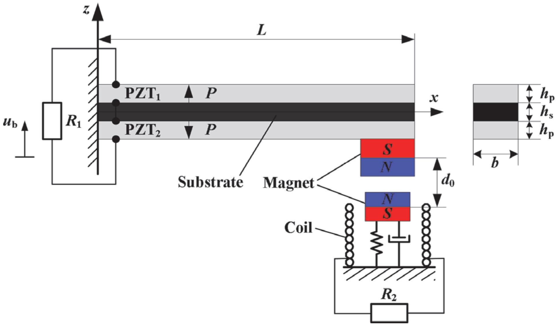
Figure 1 illustrates the schematic diagram of the proposed tunable multi-frequency HEH. It consists of a cantilevered piezoelectric oscillator with a cylindrical magnet as a proof mass and a magnetic oscillator attached on the frame. Two oscillators are coupled through the magnetic interaction, which behaves as the repulsive force. An induction coil is attached around the magnetic oscillator.
R1 and
R2 are load resistances connected to piezoelectric patches and induction coil, respectively. When the HEH is subjected to the external excitation, the mechanical strain is converted into voltage in the piezoelectric layers. Meanwhile, the relative movement between the magnet and coil induces a current in the wire, based on Faraday’s law. Note that the resonant frequencies of two oscillators are higher than their own natural frequencies due to the repulsive magnetic force. The natural frequency of the magnetic oscillator is designed to be lower than that of the piezoelectric oscillator, so that it can be used to scavenge the low-frequency vibration energy. Meanwhile, the piezoelectric oscillator can harvest the discrete high-frequency vibration energy.
The advantages of this design are as follows: (1) the output power is enhanced, because the kinetic energy can be simultaneously harnessed through piezoelectric effect and electromagnetic induction; (2) it is capable of simultaneously responding to excitation from multiple frequencies; (3) its resonant frequencies can be tuned by changing the separation distance between two magnets; (4) it has a wider bandwidth in the low-frequency range.
Figure 1.
Schematic diagram of the proposed hybrid energy harvester.
Figure 1.
Schematic diagram of the proposed hybrid energy harvester.
4. Numerical Simulation
Upon Equations (22)–(24), the performances of the HEH depend on the magnetic force, mass, stiffness, and mechanical dampings of the system. In this section, we will discuss the effects of the above parameters on the harvesting performances of the HEH. The theoretical model is numerically simulated by using the ordinary differential equation solver “ode45” in MATLAB
® (MathWorks, Natick, MA, USA). The piezoelectric material used is PZT-5H [
43]. The geometric and physical properties of the proposed HEH are given in
Table 1. Note that magnet A stands for the proof magnet, while magnet B stands for the magnetic oscillator. In the following parts, the electromechanical coupling coefficients θ
p and θ
em are determined based on these properties. The reference resistances connected to the HEH are assumed to be
R1 = 1/
Cpω
1,
R2 =
Rc = 240 Ω. The excitation acceleration is set 2 m/s
2 and the initial separation distance
d0 is 52.5 mm. The equilibrium position of the center of magnetic oscillator is set on the upper surface of the coil,
i.e.,
z2 =
hc. The mechanical damping ratio of each oscillator is set 0.02.
Table 1.
Geometric and physical properties of the hybrid energy harvester (HEH).
Table 1.
Geometric and physical properties of the hybrid energy harvester (HEH).
| Parameter | Value |
|---|
| PZT length×width×thickness (mm3) | 50 × 20 × 0.2 |
| PZT density (kg/m3) | 7500 |
| Young’s modulus of PZT layer (GPa) | 60.6 |
| Substrate length×width×thickness (mm3) | 50 × 20 × 0.24 |
| Substrate density (kg/m3) | 8920 |
| Young’s modulus of substrate (GPa) | 90 |
| Magnet A radius×thickness (mm2) | 10 × 10 |
| Magnet B outer radius×inner radius×thickness (mm3) | 9 × 4 × 7 |
| Magnet density (kg/m3) | 7800 |
| Residual magnetic flux density (T) | 1.25 |
| Spring stiffness (N/m) | 220 |
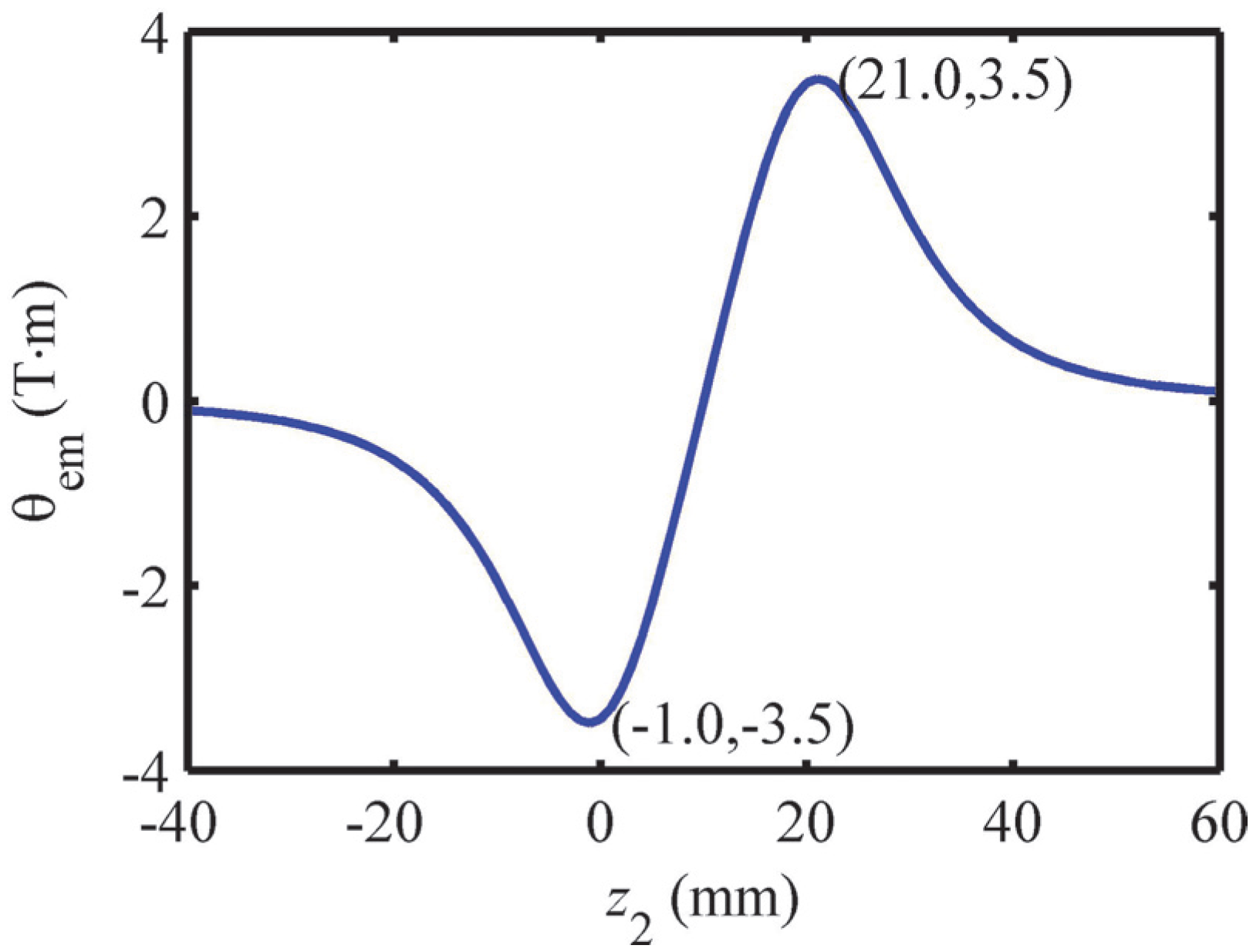
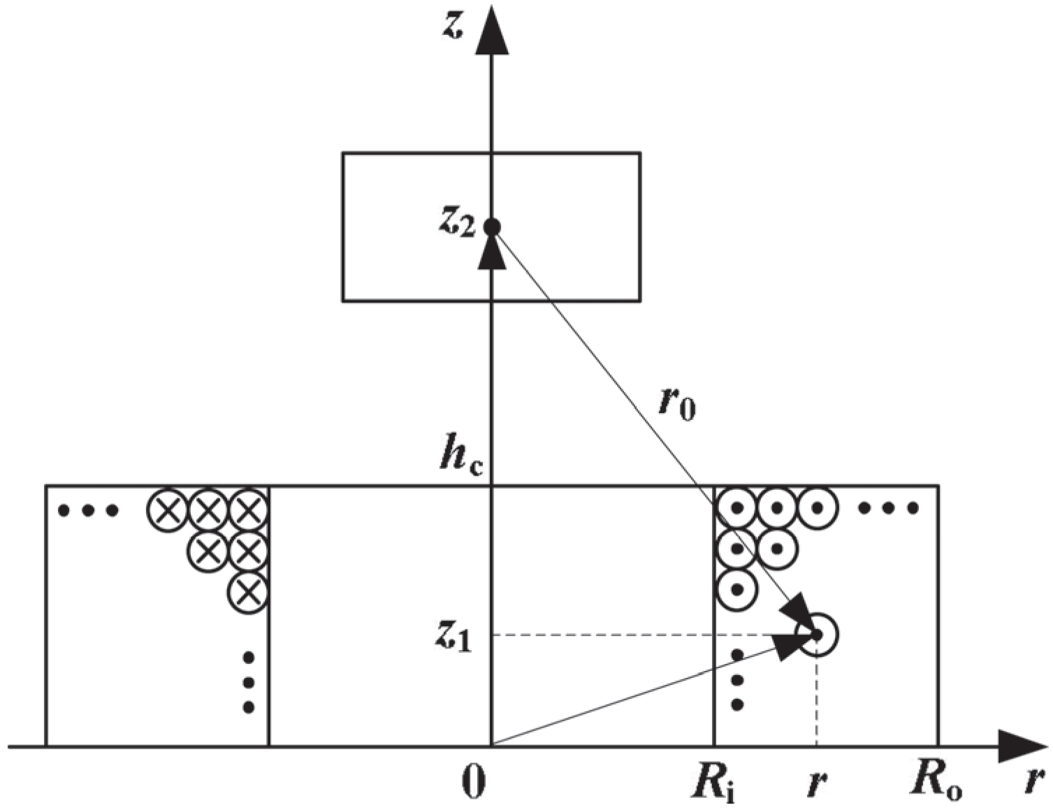
4.1. Electromagnetic Coupling Coefficient
Figure 3 shows the relationship between electromagnetic coupling coefficient θ
em and position of magnetic oscillator
z2. It seems that θ
em varies nonlinearly with the change of
z2 due to the change of magnetic field. θ
em reaches the peak values around the upper and lower surfaces of the coil, while the value is zero at the center of the coil. Because the maximum velocity of the magnetic oscillator occurs at the static balance position during the harmonic oscillation, the upper and lower surfaces of the coil are optimal equilibrium positions for the magnetic oscillator.
Figure 3.
Electromagnetic coupling coefficient versus z2.
Figure 3.
Electromagnetic coupling coefficient versus z2.
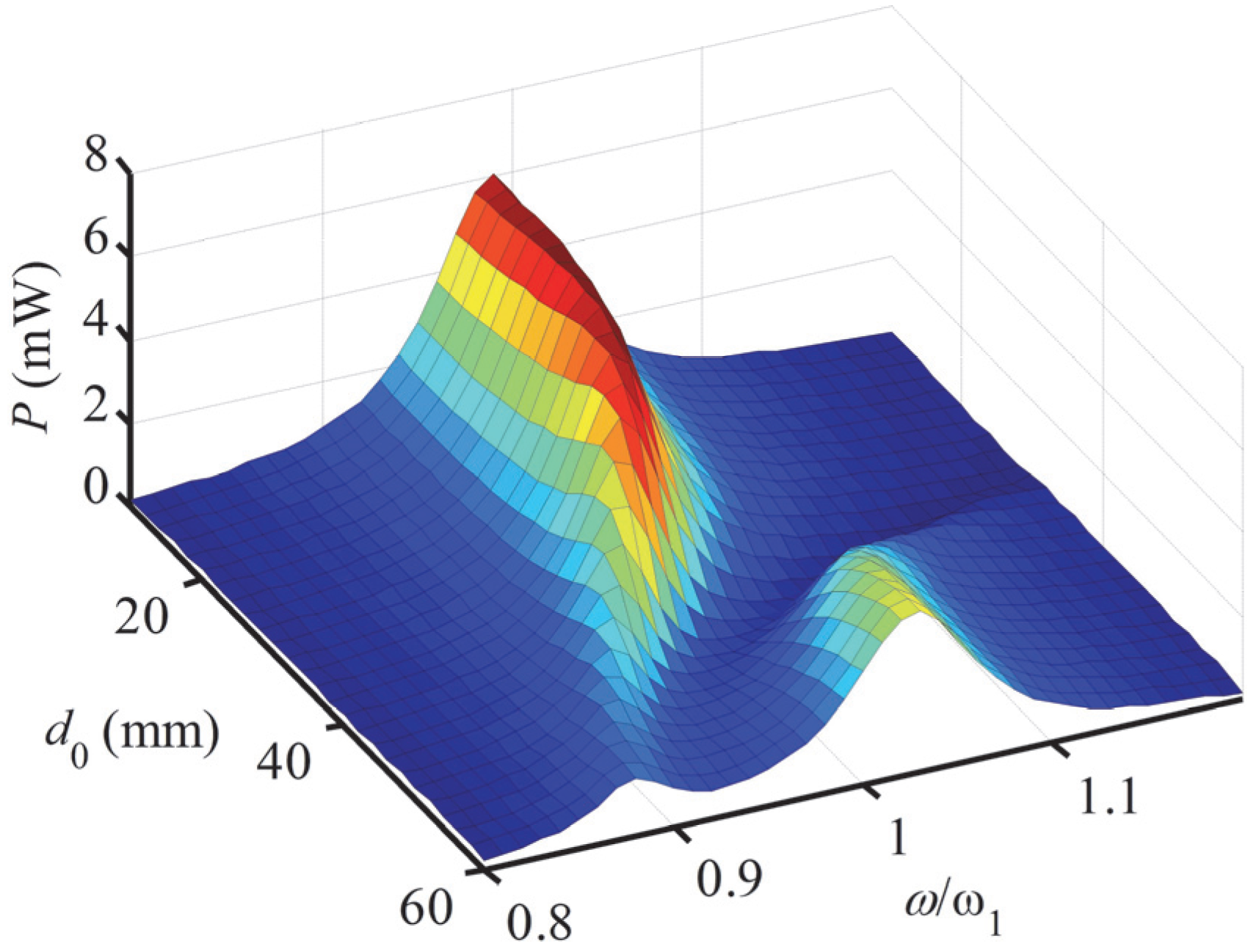
4.2. Effect of Magnetic Force on the Output Power
Figure 4 shows the effect of magnetic force on the output power of the HEH. The first and second resonant frequencies are induced by magnetic and piezoelectric oscillators, respectively. It is the typical characteristic of the multi-frequency VEH. It can be seen that both of the two resonant frequencies increase with the decreasing of
d0, which is the same as the tendency of the difference of the two resonant frequencies. Therefore, we can tune the resonant frequencies of the system by changing the initial separation distance
d0. However, when
d0 is small enough and the repulsive force is large enough, the two resonances will merge into one resonance. In this situation, the magnetic interaction acts as a rigid connection between two oscillators, so that two oscillators have the same resonant frequency around the ω
1. With the decrease of
d0, the magnitude of the first peak power gradually increases, while the one of the second peak constantly decreases. When the second peak finally disappears, the first peak reaches the maximum value. Although the magnetic force is large enough when
d0 = 10.0 mm, there is still no obvious hardening or softening response, which is the typical phenomenon in magnetic coupling nonlinear VEH [
20]. The main reason is that the difference of displacements between two oscillators (
u1−
u2) is very small under the small-amplitude excitation, so that the magnetic nonlinearity is invisible, which can be referred in Equation (9).
Figure 4.
Output power versus excitation frequency for different d0.
Figure 4.
Output power versus excitation frequency for different d0.
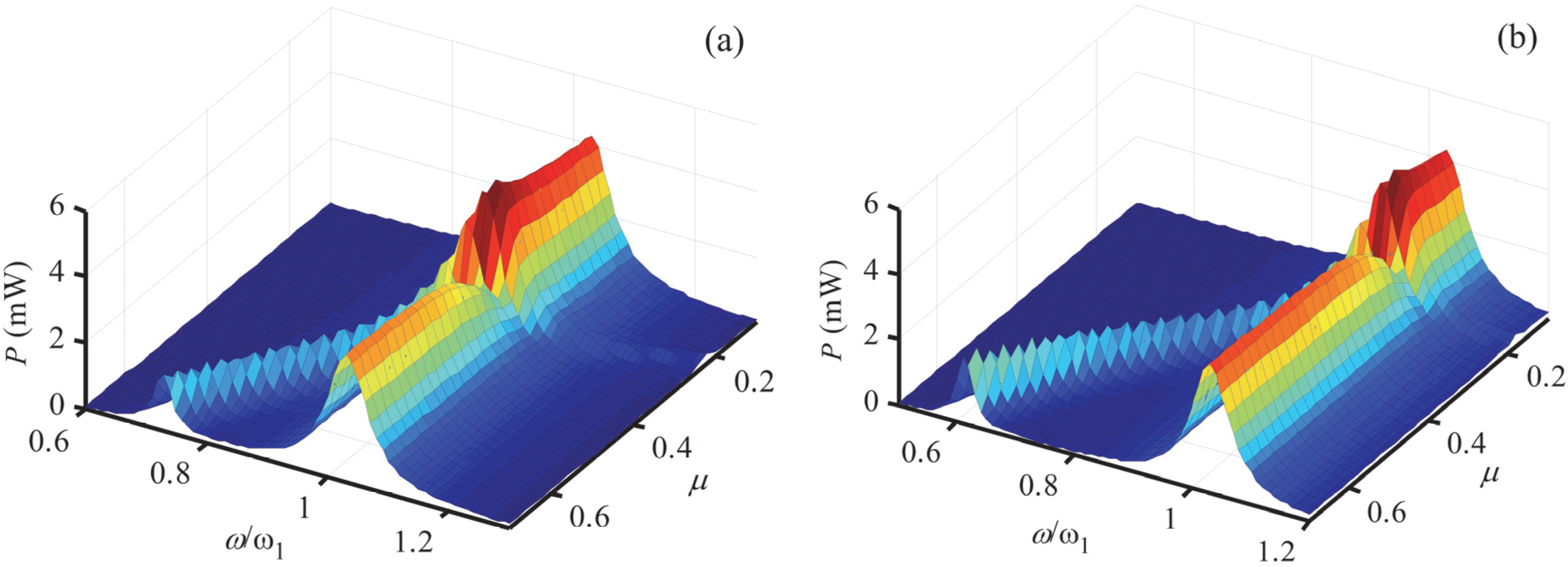
4.3. Effect of Mass Ratio on the Output Power
Define
,
[
17], μ =
M2/
M1, and α =
K2/
K1, where
M1 and
K1 are the lumped mass and stiffness of the piezoelectric oscillator, respectively. μ and α are mass and stiffness ratios, respectively. According to the properties in
Table 1,
M1 = 0.0257 kg,
K1 = 651.8 N/m,
M2 = 0.0118 kg,
K2 = 220.0 N/m, μ = 0.46, and α = 0.34. The output power of the HEH
versus excitation frequency for different mass ratio μ is illustrated in
Figure 5. For a given α, the first resonance shifts to a higher frequency with the decrease of μ. It is difficult to distinguish the tendency of the second resonant frequency, due to the mixture of two peak power. Because the HEH is used in the low-frequency environment, the dynamic characteristic of the first peak power is our research focus. The magnitude of first peak initially decreases and then increases as μ decreases. Finally, it reduces to a smaller value when the first resonance is higher enough than the second one. In a word, the mass ratio affects the resonance distribution and output power of the HEH.
Figure 5.
Output power versus excitation frequency for different μ: (a) α = 0.34; (b) α = 0.23.
Figure 5.
Output power versus excitation frequency for different μ: (a) α = 0.34; (b) α = 0.23.
For the given μ, the magnitude of the first peak power is enhanced with the smaller α (α = 0.23), which is contrary to the change of the second peak power. However, the first resonance shifts to a lower value with the decreasing of α. Under the same excitation condition, the smaller α is, the more vibration energy can be harvested by magnetic oscillator. The second resonant frequency remains almost unchanged.
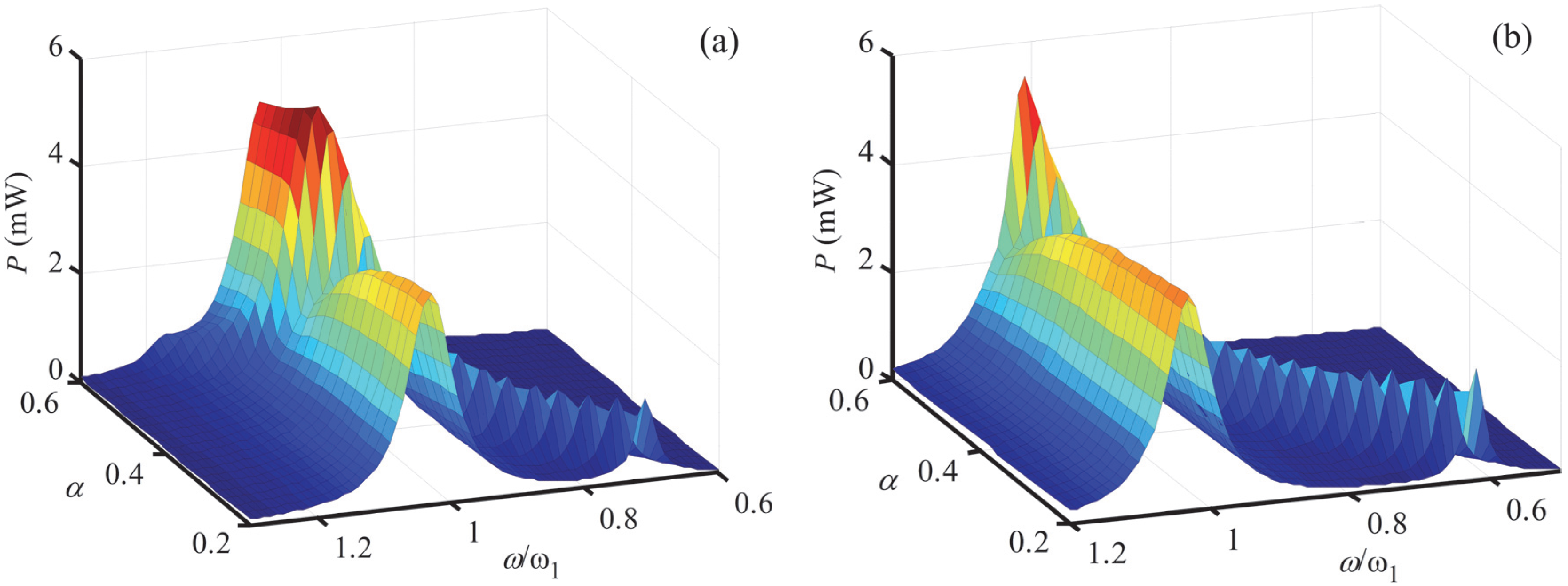
4.4. Effect of Stiffness Ratio on the Output Power
Figure 6 depicts the effect of stiffness ratio α on the output power of the HEH. For a given μ, the first resonant frequency increases as α increases, while the magnitude of the first peak initially decreases, then increases, and finally reduces to a smaller value. It also shows that α has almost no effect on the second resonance. When α remains unchanged, the larger μ is, the more the magnitude of the first peak increases. This conclusion is identical with that obtained before. Therefore, the stiffness ratio can also be used to alter the performance of the HEH.
Figure 6.
Output power versus excitation frequency for different α: (a) μ = 0.46; (b) μ = 0.60.
Figure 6.
Output power versus excitation frequency for different α: (a) μ = 0.46; (b) μ = 0.60.
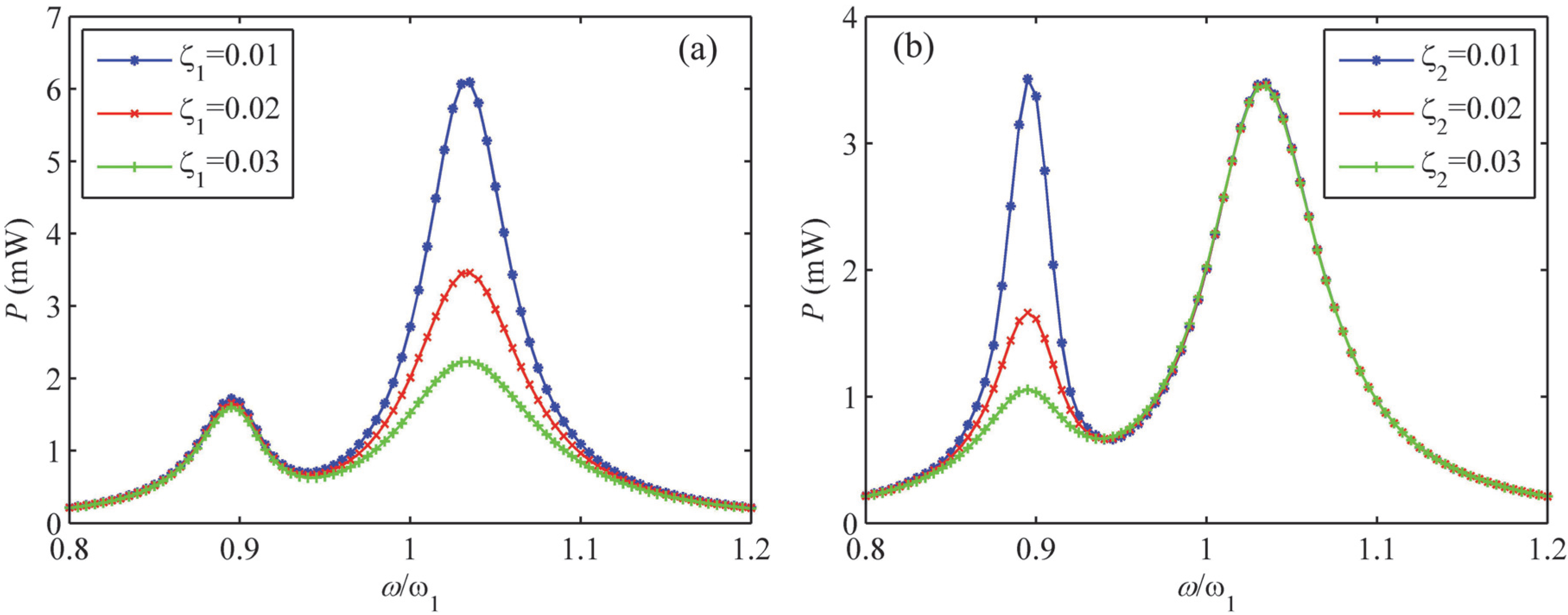
4.5. Effects of Mechanical Damping Ratios on the Output Power
Figure 7 shows the effects of mechanical damping ratios ζ
1 and ζ
2 on the output power of the HEH, respectively. It can be seen that ζ
1 mainly affects the performance of the second peak induced by the piezoelectric oscillator, while ζ
2 mainly affects that of the first peak induced by the magnetic oscillator. With the increase of ζ
1, the magnitude of the second peak output power constantly decreases, but the bandwidth increases. The magnitude of the first peak power slightly decreases. These effects are the same as that induced by ζ
2.
Figure 7.
Output power versus excitation frequency for different mechanical damping ratios: (a) ζ1; (b) ζ2.
Figure 7.
Output power versus excitation frequency for different mechanical damping ratios: (a) ζ1; (b) ζ2.
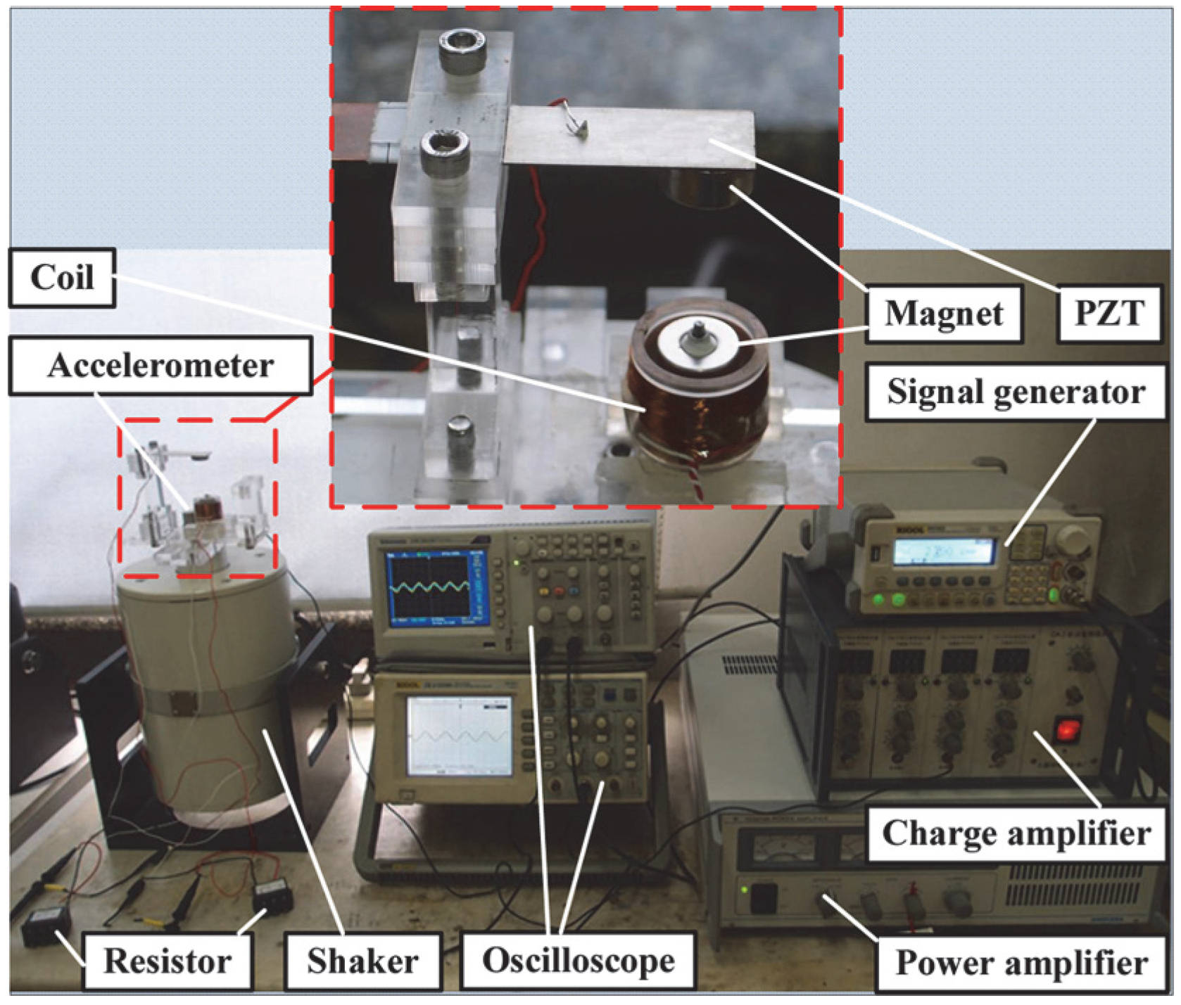
5. Experimental Method
Figure 8 shows the fabricated macro-scale prototype of the proposed HEH and the experimental system. The substrate of the cantilever beam is made of Phosphor Bronze (ALB Copper Alloys Co., Ltd., Xiamen, China). It is sandwiched between two PZT-5H patches (Baoding Hongsheng Acoustics Electron Apparatus Co., Ltd., Baoding, China), which are connected in series. Two permanent magnets are NdFeB (Ningbo Hony Technology Co.,Ltd., Ningbo, China). They have opposite directions of magnetization. The magnetic proof mass is cylindrical. The magnet of the magnetic oscillator is a magnetic ring. It is attached to an aluminum rod, which is bolted on the frame. The rod is used to keep the magnet moving on the vertical direction. The copper wire coil (Changzhou Wujin Enameled Wire Factory Co., Ltd., Changzhou, China) is placed along the motion direction of the magnetic oscillator. The geometric and physical properties of the prototype are according to
Table 1. The internal resistance of the coil is 240 Ω. The experimental system consists of an electromagnetic shaker (JZK-50) (Sinocera Piezotronics Inc., Yangzhou, China), a signal generator (DG-1022) (Rigol Technologies Inc., Beijing, China), a power amplifier (YE5874A) (Sinocera Piezotronics Inc., Yangzhou, China). The base excitation acceleration was measured by an accelerometer (YD64-310) (Qinhuangdao Xinheng Electronic Technology Co. Ltd., Qinhuangdao, China). The output voltage was continuously monitored by the oscilloscopes DS-5102MA (Rigol Technologies Inc., Beijing, China) and TDS-1012C (Tektronix China Ltd., Shanghai, China).
Figure 8.
Prototype of the HEH and the experimental system.
Figure 8.
Prototype of the HEH and the experimental system.
Upon the numerical simulation, the theoretical resonances of the piezoelectric and magnetic oscillators are about 26 Hz and 22 Hz, respectively. Thus, we sweep the excitation frequency from 16 to 32 Hz in the following experiments. The base excitation generated by the electromagnetic shaker is harmonic and the acceleration is set 2 m/s2. The initial separation distance between two magnets d0 is 52.5 mm.
In order to evaluate the performance of the proposed HEH, four different energy harvesters with single conversion mechanism were also developed and experimentally verified for comparison under the same excitation condition. When the induction coil around the magnetic oscillator is open-circuit, there will be no electromagnetic damping induced in the energy harvesting system. Accordingly, the HEH changes into a conventional multi-frequency PEH (MPEH) with magnetic oscillator, as reported in reference [
17]. When the piezoelectric layers are in the short-circuit condition, a conventional multi-frequency EMEH (MEMEH) with a magnetic oscillator can be developed. The magnetic oscillator and induction coil are the component units of the 1DOF linear EMEH (LEMEH). The combination of the LPEH and LEMEH is named LVEH. Its output power frequency response is compared with that of the HEH.
6. Results and Discussion
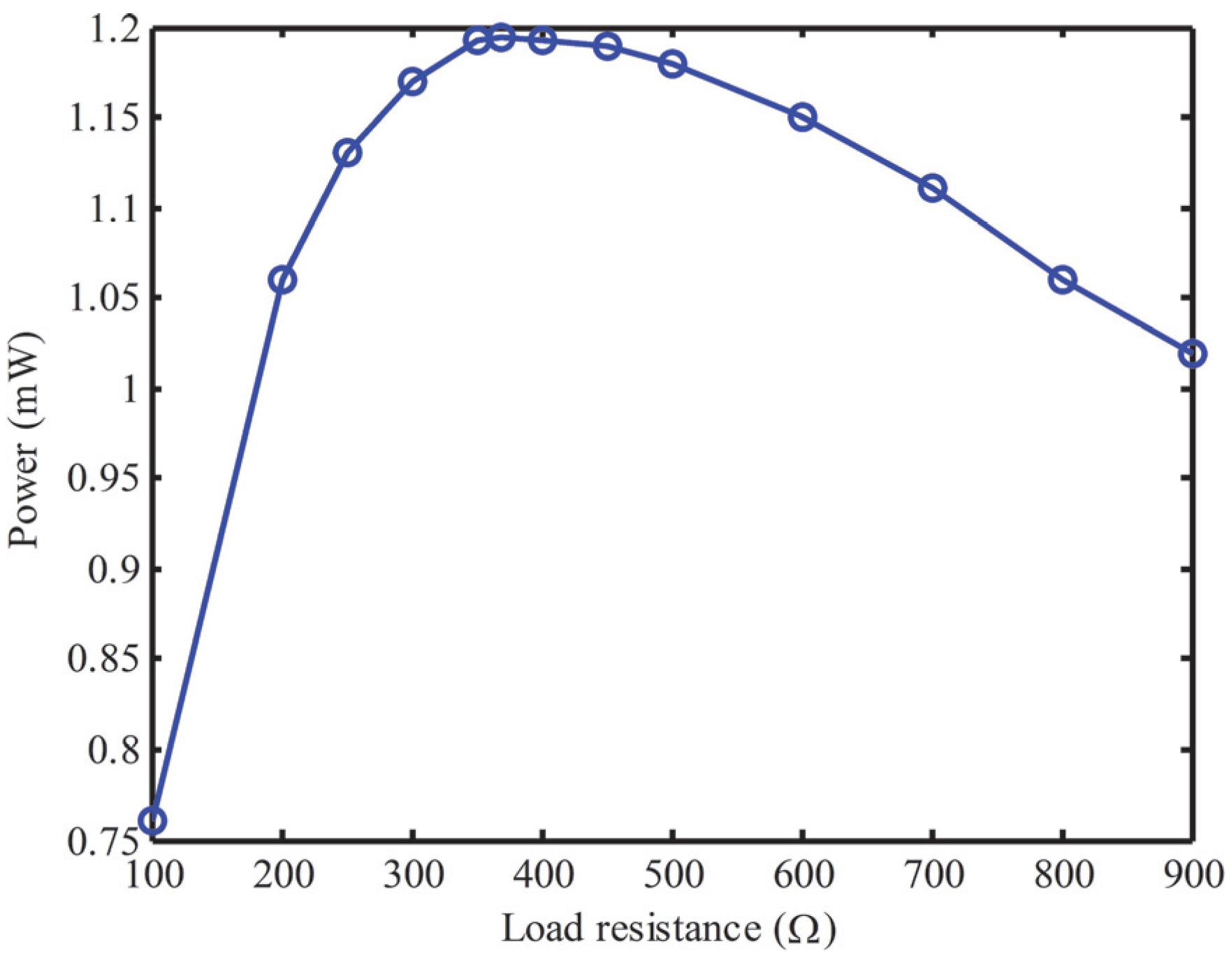
To measure the optimal load resistance matched to the coil, the piezoelectric layers are short-circuit. There are two peak output powers for the configuration of two magnetic coupled oscillators. The first peak is induced by the magnetic oscillator, while the second one is induced by the piezoelectric oscillator.
Figure 9 shows the first peak output power delivered to the load resistance
R2 for the MEMEH at resonant frequency. The maximum power is 1.2 mW at 22.8 Hz with the load resistance 370 Ω. The second peak output power delivered to the load resistance
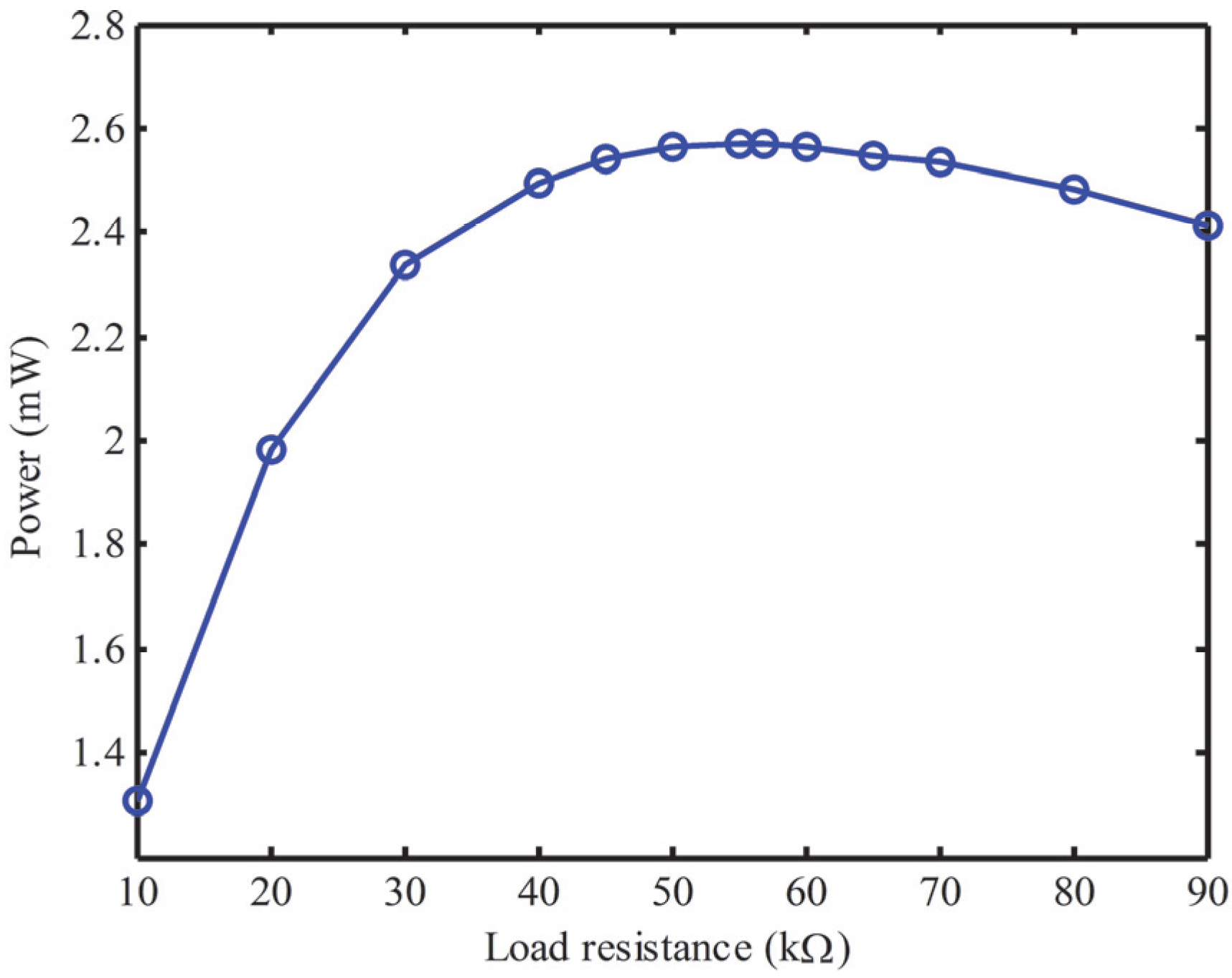
R1 for the MPEH at resonant frequency is shown in
Figure 10. The induction coil around the magnetic oscillator is open-circuit. With the increasing of
R1, the power reaches the maximum 2.57 mW at 57 kΩ. The corresponding resonant frequency is 25.8 Hz. By using the logarithmic decrement method, the measured mechanical damping ratios of piezoelectric beam and magnetic oscillator with magnetic interaction are 0.023 and 0.024, respectively.
Figure 9.
Output power with different load resistances for the MEMEH.
Figure 9.
Output power with different load resistances for the MEMEH.
Figure 10.
Output power with different load resistances for the MPEH.
Figure 10.
Output power with different load resistances for the MPEH.
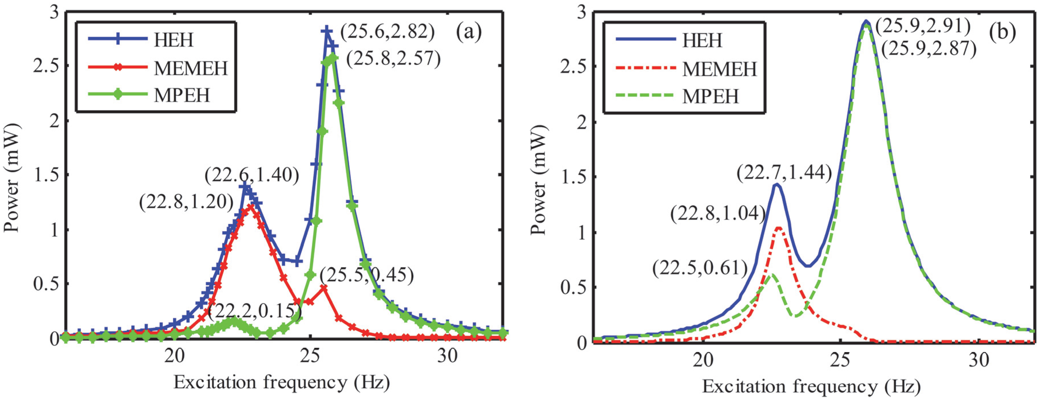
Figure 11a,b shows the experimental and numerical comparisons of the frequency-response for the HEH, MPEH and MEMEH, respectively. The initial distance
d0 is still 52.5 mm. The loads connected to the HEH are the optimal values determined from the MPEH and MEMEH. It can be seen in
Figure 11a that each harvester has two peak output powers. For HEH, the measured peak output powers are 1.40 mW at 22.6 Hz and 2.82 mW at 25.6 Hz. In view of the low-frequency applications, the first peak output power is the research focus. The first peak of the HEH increases by 16.7% and 833.3% compared with the first peaks of the MEMEH (1.2 mW) and the MPEH (0.15 mW), respectively. The frequency response of the HEH completely covers that of the MPEH and MEMEH. That is to say, the hybrid transduction mechanism is superior to the multi-frequency devices with single conversion mechanism in broadening the bandwidth and improving the generating performance. We can find that the simulation results of the HEH are in good agreement with the experimental results. The inaccuracies between theoretical and simulation results for the MPEH and MEMEH are significant. We think that these errors may be due to the damping change between the magnetic oscillator and the aluminum rod with varying vibration frequencies. Besides, the effective stiffness of the spring varies with the change of effective length during the oscillation, which may be another factor.
Figure 11.
Frequency responses for the HEH, MEMEH, and MPEH: (a) experimental results; (b) numerical results.
Figure 11.
Frequency responses for the HEH, MEMEH, and MPEH: (a) experimental results; (b) numerical results.
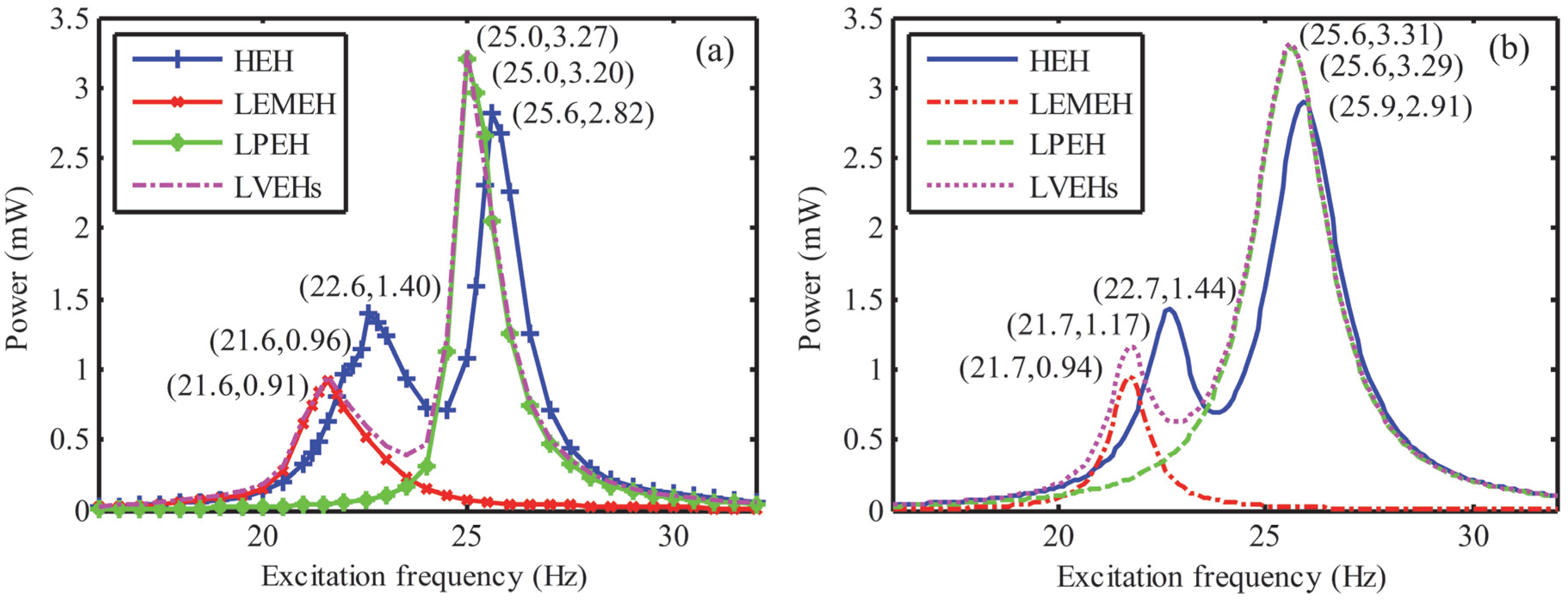
Figure 12a,b illustrates the numerical and experimental comparisons of the output power for the HEH, LEMEH, LPEH and LVEHs, respectively. The connected load resistances keep still. Due to the repulsive magnetic force, the measured first resonance of the HEH (22.6 Hz) is higher than that of the LVEHs (21.6 Hz) and the second one (25.6 Hz) is higher than that of the LVEHs (25 Hz). Moreover, the first peak power of the HEH (1.4 mW) is 2.36 times more than that of the LVEHs (the sum of 0.08 mW from LPEH and 0.49 mW from LEMEH) at the same excitation frequency. Meanwhile, it increases by 45.8% compared to that of the LVEHs, although the second peak power of the HEH decreases by 13.8%. Obviously, the repulsive magnetic force can suppress the oscillation of the piezoelectric oscillator, but enhance the oscillation of the magnetic oscillator. The half-power bandwidth of the first peak power for the HEH is about 2.8 Hz, which is wider than that of the LEMEH (1.9 Hz). It is clear that the generating performances of the LPEH and LEMEH are greatly improved by the magnetic coupling multi-frequency structure and hybrid transduction mechanism in the low-frequency range. Consequently, magnetic interaction is an effective approach to improve the performance of the micro energy harvester in the low-frequency range. The numerical results show good agreement with the experimental results. Note that the measured mechanical damping ratios of piezoelectric and magnetic oscillators without magnetic interaction are 0.025 and 0.02, respectively. That is to say, magnetic interaction can add extra damping to the magnetic oscillator and cut down the damping of the piezoelectric oscillator. The simulation results for the LEMEH shows good agreement with the experimental results. Accordingly, the model of the electromagnetic coupling coefficient θ
em is reasonable and valid.
Figure 12.
Frequency responses for the HEH, LEMEH, LPEH and LVEHs: (a) experimental results; (b) numerical results.
Figure 12.
Frequency responses for the HEH, LEMEH, LPEH and LVEHs: (a) experimental results; (b) numerical results.
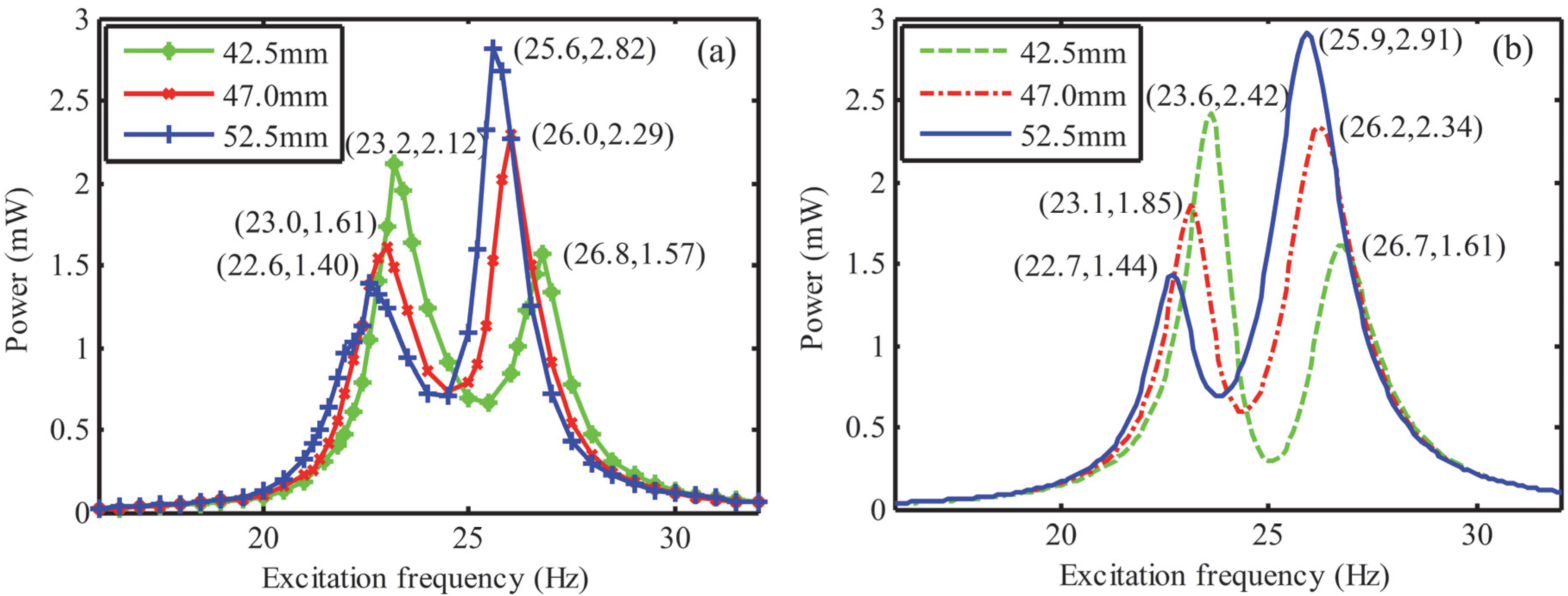
Figure 13 provides the investigation on the effects of the initial separation distance
d0 between two magnets on output power. The measurement was performed at three arbitrary different separation distances 42.5, 47.0, and 52.5 mm. For the sake of contrastive analysis, the excitation acceleration was controlled at 2 m/s
2. It shows that the resonant frequencies shift to the right with the decreasing of the initial separation distance, which is consistent with the simulation result. It can be attributed to the increasing repulsive magnetic force and the magnetic stiffness. Consequently, the resonant frequencies can be tuned by adjusting the separation distance according to the ambient excitation frequency. Furthermore, the amplitude of the first peak output power is another issue which deserves concern. Contrary to the resonant frequency, the peak output power for the first resonance goes up continuously with the decreasing of the separation distance. In the future designing, we need to make a trade-off between the resonance and peak output power. With the decrease of
d0, the error between experimental and numerical results of the first peak power increases, because the mechanical damping ratios were kept constant in the theoretical model, while the actual values are variable. Moreover, the damping ratio of magnetic oscillator increases more significantly than that of the piezoelectric oscillator.
Figure 13.
Frequency responses for the HEH with different separation distances d0: (a) experimental results; (b) numerical results.
Figure 13.
Frequency responses for the HEH with different separation distances d0: (a) experimental results; (b) numerical results.
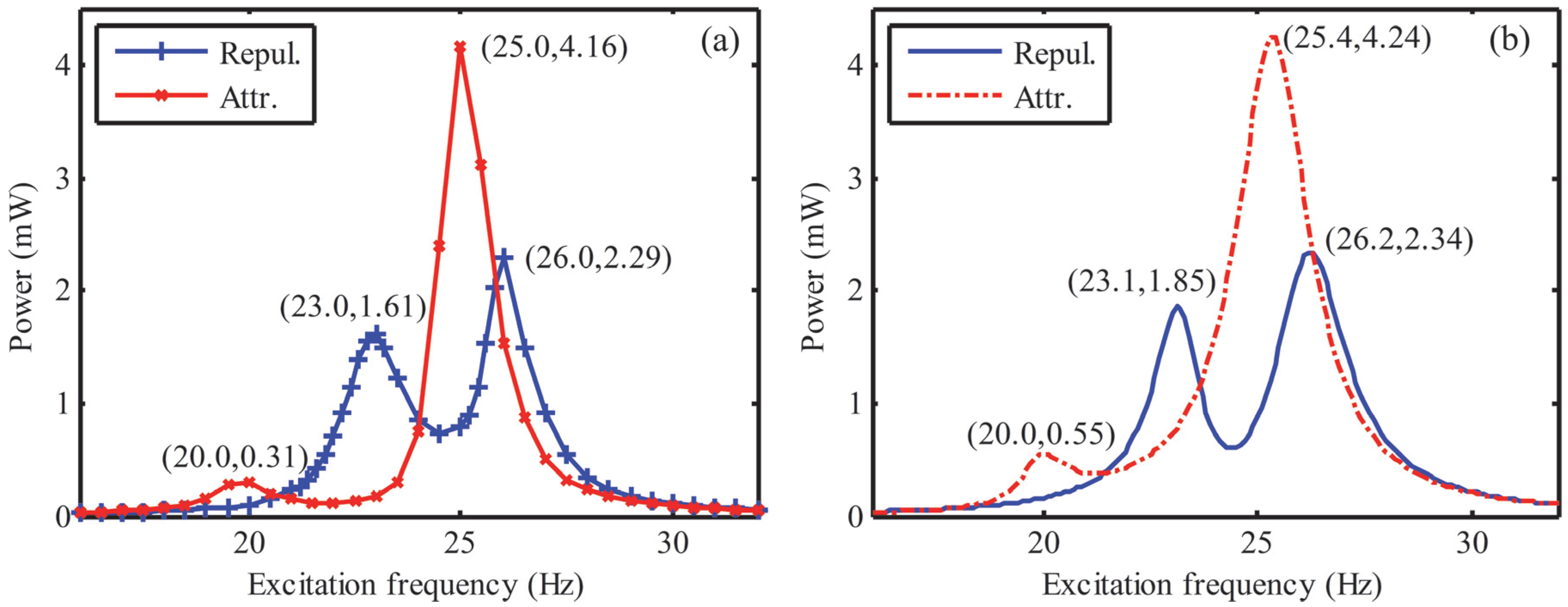
Figure 14 shows the output power for the HEH with different directions of magnetic force. Two magnets will attract each other with the same magnetization direction, while they will repel each other in opposite direction. Due to the attractive force, the initial distance reduces to 47 mm. As a result of the attractive force, the resonant frequencies shift to the left, while the first peak output power decreases sharply as compared to that of the HEH with repulsive force. On the contrary, the second peak output power is obviously enhanced. That is to say, the generating efficiency of piezoelectric element is much higher than that of the electromagnetic element with the attractive force. The theoretical value of the first peak power for the HEH is lower than the measured value. The reason is that attractive force induces more deformation of the piezoelectric beam. However, the mechanical damping of magnetic oscillator is also enhanced simultaneously. In this case, the HEH is more suitable for scavenging vibration energy in the high-frequency range. However, the attractive force is still a choice for energy harvesting at the lower excitation frequency. Similarly, the direction of magnetic force needs to be selected properly depending on the excitation frequency and electric power demands.
Figure 14.
Frequency responses for the HEH with different directions of magnetic force: (a) experimental results; (b) numerical results.
Figure 14.
Frequency responses for the HEH with different directions of magnetic force: (a) experimental results; (b) numerical results.


