1. Introduction
Over the last decade we have witnessed a tremendous progress in the development of regenerative laser amplifiers with repetition rates from 100 kHz up to 1 MHz. These laser systems are widely used as laser material processing tools, where together with a high pulse energy in the Micro-Joule range high pulse repetition-rates are required to minimize production times [
1,
2]. A Megahertz repetition rate is also attractive for applications in nuclear, heavy ion and atomic physics enabling synchronization to the round trip times of particle storage rings [
3,
4,
5]. Furthermore, high repetition rate picosecond laser systems are routinely used for photo cathode based electron sources seeding linear accelerator driven light sources [
6].
Commonly,
β-Barium Borate (BBO), Rubidium Titanyle Phosphate (RTP), Potassium Dihydrogen Phosphate (KDP) or Potassium Dideuterium Phosphate (KD*P) are used for Pockels cells at a wavelength around 1 μm. As both KD*P and KDP show piezoelectric ringing at repetition rates higher than 10 kHz only RTP and BBO remain. For given apertures and crystal lengths the half wave voltage of BBO is more than five times higher when compared to RTP due to the electro-optic coefficients. Since the average power required for the electronic switch scales linearly with the repetition rate and with the square of the voltage, RTP is often preferred for high repetition rate applications. On the other hand, based on practical experience much higher optical average powers can be realized with BBO since RTP suffers from optically induced birefringence. Furthermore, a much higher polarization contrast ratio can be obtained with BBO. This was observed when comparing BBO and RTP at long term operation in a regenerative Nd:YVO
amplifier up to 300 kHz [
7].
Picosecond regenerative amplifiers with high-gain materials such as Nd:YVO
have already been demonstrated up to a repetition rate of 850 kHz [
8]. Regenerative amplification in broadband gain media such as Yb:CaF
and Yb:CAlGO has been shown up to 500 kHz [
9] and up to 200 kHz with Yb:YVO
[
10]. A 100 W picosecond thin-disk Yb:YAG regenerative chirped-pulse amplifier (CPA) system was demonstrated up to 300 kHz [
11]. Up to 1.7 MHz has been already achieved with a regenerative Ti:Sapphire amplifier at a shorter wavelength of 800 nm [
12]. Complementary to the increase in the repetition rate of regenerative amplifiers, a fast evolution of mode-locked ultra-short pulse oscillators [
13,
14] with reduced repetition rate down to 1 MHz and with higher single pulse energies up to the μJ-level took place. Recently, a Gd:YVO
cavity dumped oscillator with 1 MHz repetition rate using an RTP Pockels cell was reported [
15]. However, a more flexible down scale of the repetition rate is possible with regenerative amplifiers compared to mode-locked oscillators.
Here, we present results of regenerative amplification with a maximum repetition rate of 2 MHz for Yb:YAG and 1 MHz for Yb:CaF
using a BBO Pockels cell. These are to our knowledge the highest repetition rates achieved with Ytterbium-doped laser materials. Here, we used active mirrors with a thickness between 1–3 mm which give an adequate thermal management for a high beam quality at laser average powers up to 10 W. The high single-pass gain between 20% and 30% is advantageous for MHz repetition rates compared to 10% usually achieved within thin disk amplifiers [
11]. Our work is embedded in HZDR’s development of diode-pumped Petawatt laser (PENELOPE) comprising active mirror amplifiers in the front-end up to the 100 mJ level [
16].
2. Experimental Section
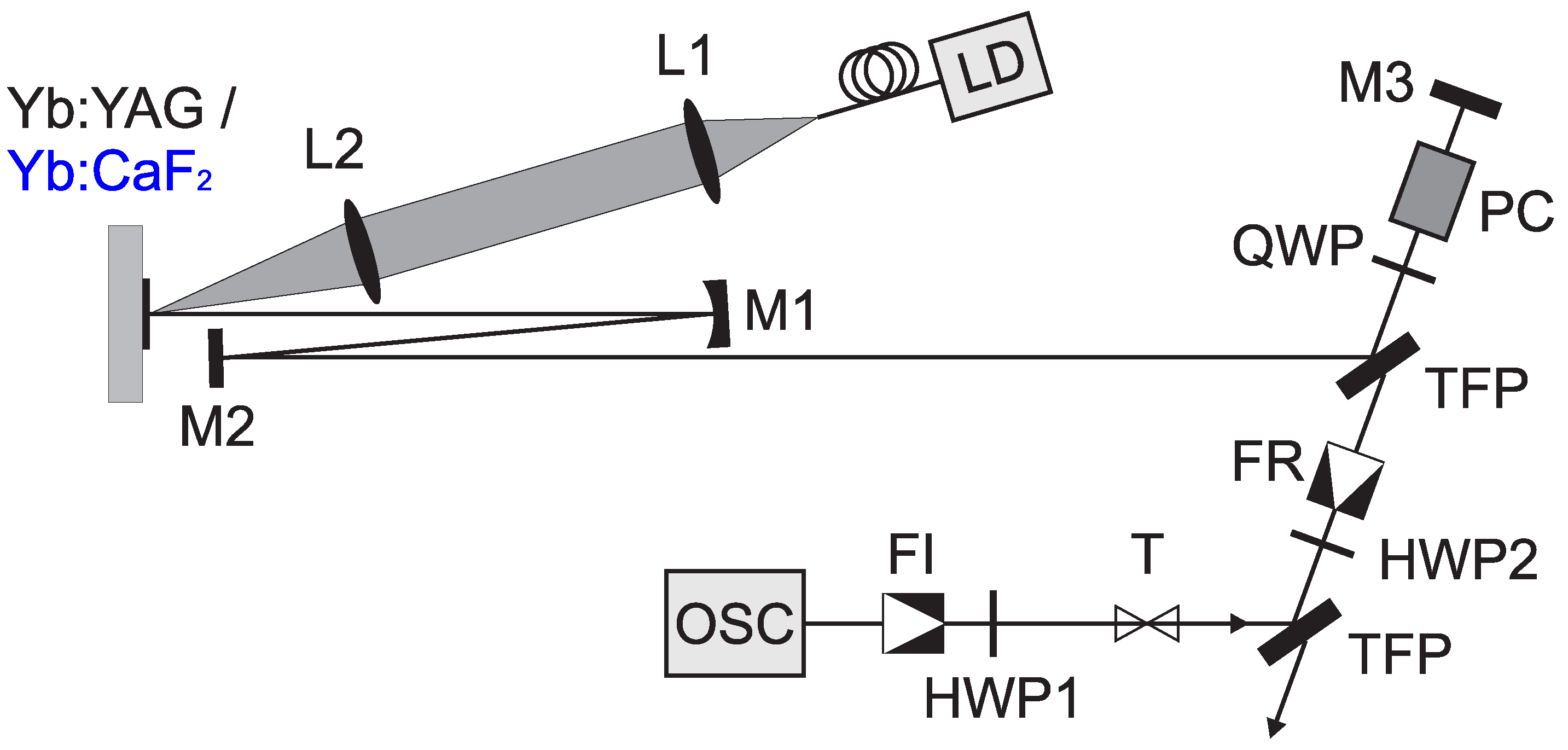
Figure 1 shows the setup of the regenerative amplifier using either Yb:YAG or Yb:CaF
as gain medium. In our experiments we used single crystalline Yb:YAG (produced by FEE Ltd., Idar-Oberstein, Germany) with an Yb
-concentration of 10% and a thickness of 1 mm as well as Yb:CaF
(produced by CIMAP, Université de Caen, Caen, France) with an Yb
-concentration of 4.5% and a thickness of 2.5 mm. The laser disks with a diameter of 12.5 mm, anti-reflection (AR) coating on the front-side and high-reflection (HR) coating on the rear side were glued on a water-cooled heat sink. Without saturation effects about 90% of the pump light is absorbed in the Yb:YAG crystal and 94% in the Yb:CaF
crystal.
Figure 1.
Experimental setup: OSC, fs mode-locked Yb:KGW oscillator; FI, Faraday isolator; FR, Faraday rotator; TFP, thin-film polarizer (angle of incidence: 62); QWP, HWP1 and HWP2, quarter/half-wave plates; T, spherical lens telescope (magnification: 1); PC, BBO-Pockels cell; LD, 11 W fiber coupled laser diode; L1, L2, spherical lenses with 25 mm diameter ( = 50 mm, = 75 mm); M1, dielectric concave mirror with radius of curvature: 300 mm; M2, M3, dielectric flat mirrors (HR 0, 1010–1060 nm).
Two 11 W fiber-coupled laser diodes with a fiber core diameter of 105 μm and an NA of 0.15 were used for pumping at either at 940 nm (for Yb:YAG) or 978 nm (for Yb:CaF). The pump light was collimated and re-focused into the gain media by a spherical lens telescope having a magnification of 1.5 (L1 and L2), while pump and laser beams were separated in angular domain. A concave mirror (M1) with 300 mm radius of curvature, a distance of 165 mm between M1 and the active mirror (Yb:YAG or Yb:CaF) and a cavity length of 1.3 m result into a mode-size diameter of 130 μm (1/e) at the gain media.
As the seed pulse source, an Yb:KGW fs-oscillator (Mikan, Amplitude Systems Ltd., Pessac, France) was used providing an average output power of 1 W at a repetition rate of 78 MHz. Mode matching between oscillator and regenerative amplifier especially the beam divergence was obtained by aligning the lens separation of the telescope (T). We used a water-cooled double-crystal BBO Pockels cell with a size of 3 mm × 3 mm × 20 mm for each crystal (produced by Leysop Ltd., Basildon, UK) for pulse picking as well as cavity-dumping. The optical propagation is along the c-axis of the crystal whilst the electric field is along the a-axis. Non-picked pulses are also amplified by one pass here. Therefore, the seed power was reduced to 50 mW after isolation (FI) by adjusting the half-wave plate HWP1.
Furthermore, a directly water-cooled Pockels cell driver in bridge configuration with a maximum repetition rate of approximately 5 MHz at a quarter-wave voltage of 2.2 kV was developed by Bergmann Messgeraete Entwicklung KG [
17]. An electrical average power of 1 kW is supplied for a repetition rate of 5 MHz at 2.2 kV. The cavity length of the laser was adapted to the switching times (5 ns) of the Pockels cell driver.
3. Results and Discussion
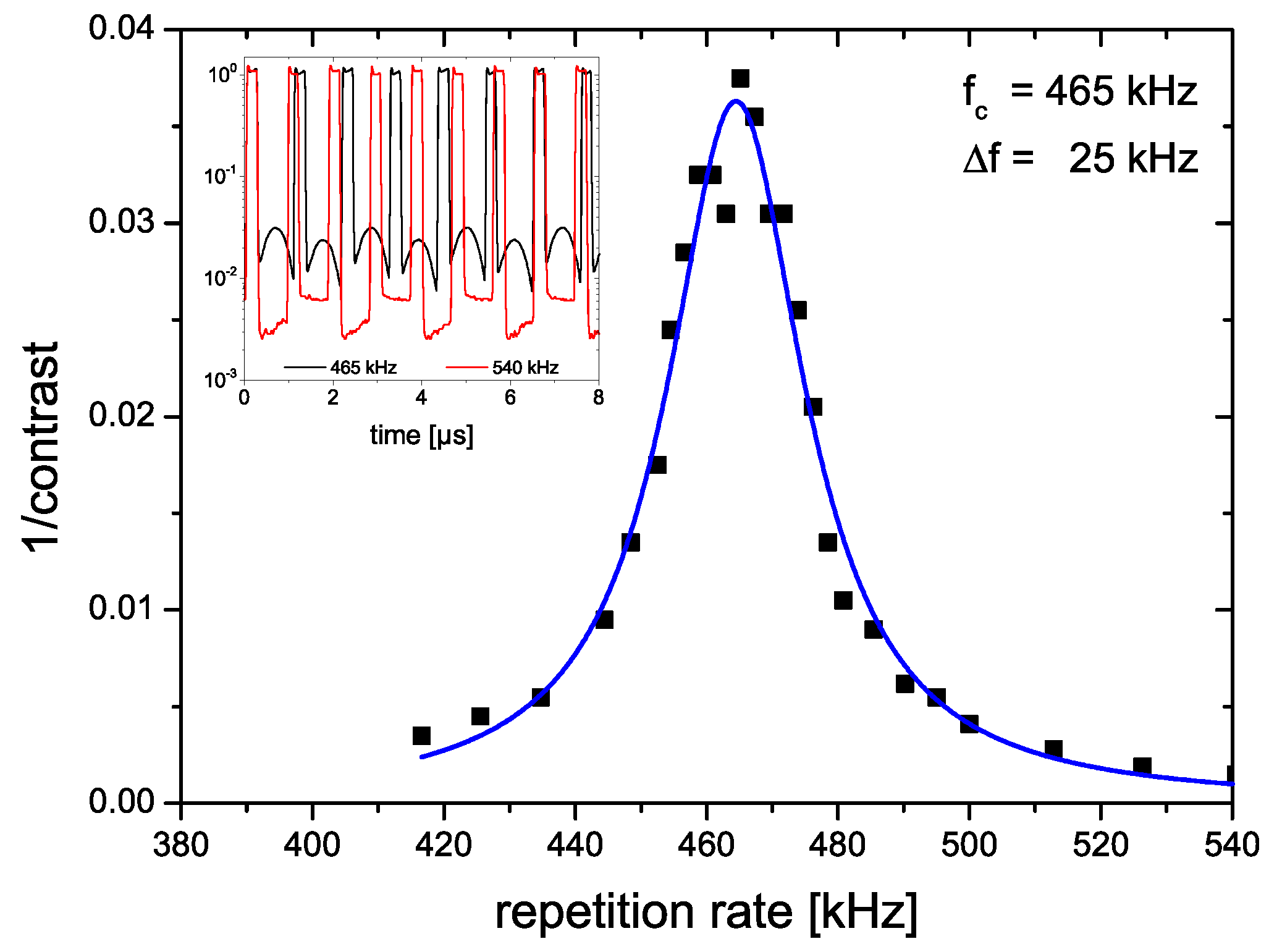
Before laser operation we analyzed the dynamic polarization contrast of the BBO Pockels cell at high repetition rates (see
Figure 2). While we obtained a contrast of more than 1:2000 at low repetition rates it was reduced by piezoelectric ringing of the BBO crystal with a resonance frequency of 465 kHz. Outside this spectral linewidth (in this case 25 kHz) the measured polarization contrast was suitable for laser operation (see inset
Figure 2).
Figure 2.
Dynamic polarization contrast of the BBO Pockels cell vs. repetition rate when supplied voltage = 0; Inset: Polarization contrast vs. time at two repetition rates.
Figure 2.
Dynamic polarization contrast of the BBO Pockels cell vs. repetition rate when supplied voltage = 0; Inset: Polarization contrast vs. time at two repetition rates.
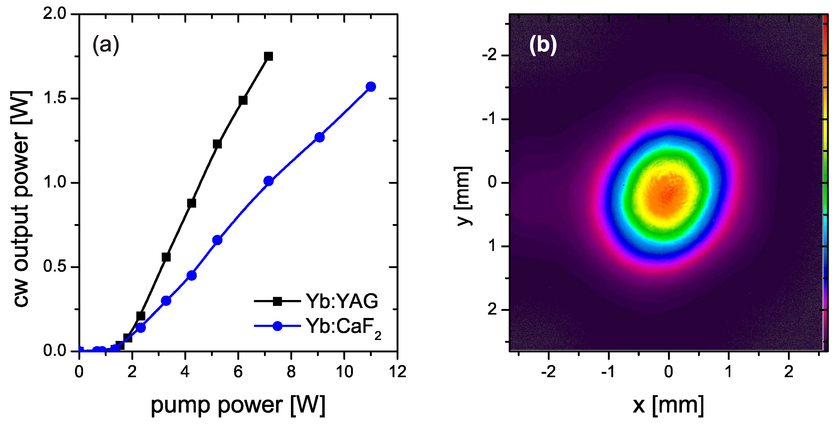
Figure 3.
(a) Laser output power vs. pump power at continuous-wave operation; (b) output beam profile with a size of 2.8 mm (D4σ x width) and 2.5 mm (D4σ y width).
Figure 3.
(a) Laser output power vs. pump power at continuous-wave operation; (b) output beam profile with a size of 2.8 mm (D4σ x width) and 2.5 mm (D4σ y width).
The resonator quality including the Pockels cell (switched off) was checked in continuous-wave (cw) operation using the QWP and TFP for output coupling (see
Figure 3a). A higher slope efficiency of 32% was measured for Yb:YAG compared to Yb:CaF
(17%). This can be explained by a different gain and loss balance considering the emission section, the degree of output coupling at the TFP and the transmission loss of around 2% for the Pockels cell. The quarter-wave plate was adjusted in order to optimize the output power at the maximum pump power separately for both gain media. In pulsed operation the average output power was set to 1 W while a slightly higher pump power of 5 W (Yb:YAG) and 8 W (Yb:CaF
) was required as compared to cw-mode. The output beam profile of the Yb:YAG laser cavity is shown in
Figure 3b similar to case of Yb:CaF
. A beam quality factor of better than
can be given which was measured with a Shack-Hartmann sensor (Optocraft, Erlangen, Germany; SSHCam HR-150-GE) [
18].
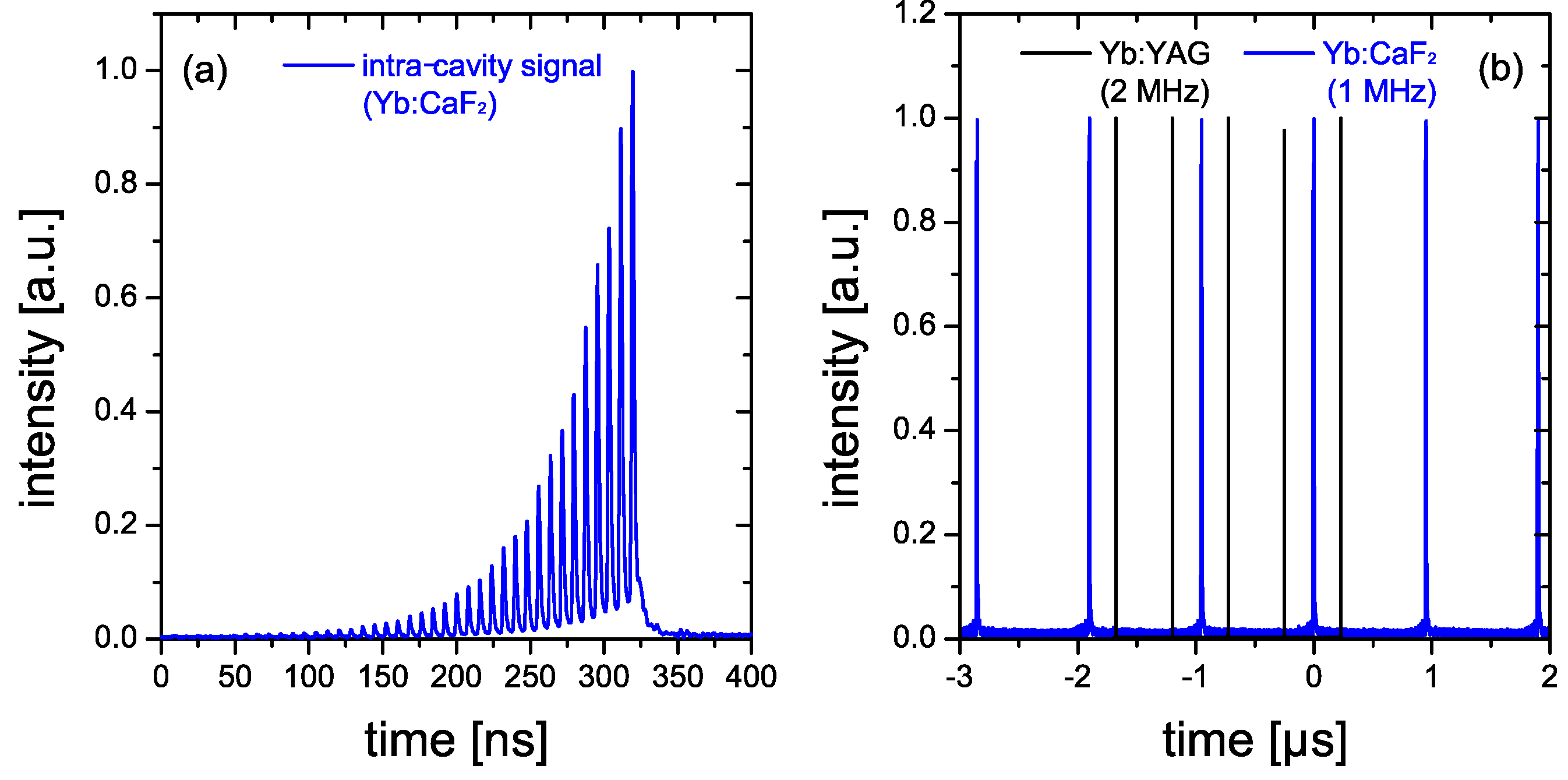
Figure 4.
Pulse train measurement: (a) intra-cavity signal showing 40 round-trips in the case of Yb:CaF; (b) output signal at 1 MHz for Yb:CaF and 2 MHz for Yb:YAG.
Figure 4.
Pulse train measurement: (a) intra-cavity signal showing 40 round-trips in the case of Yb:CaF; (b) output signal at 1 MHz for Yb:CaF and 2 MHz for Yb:YAG.
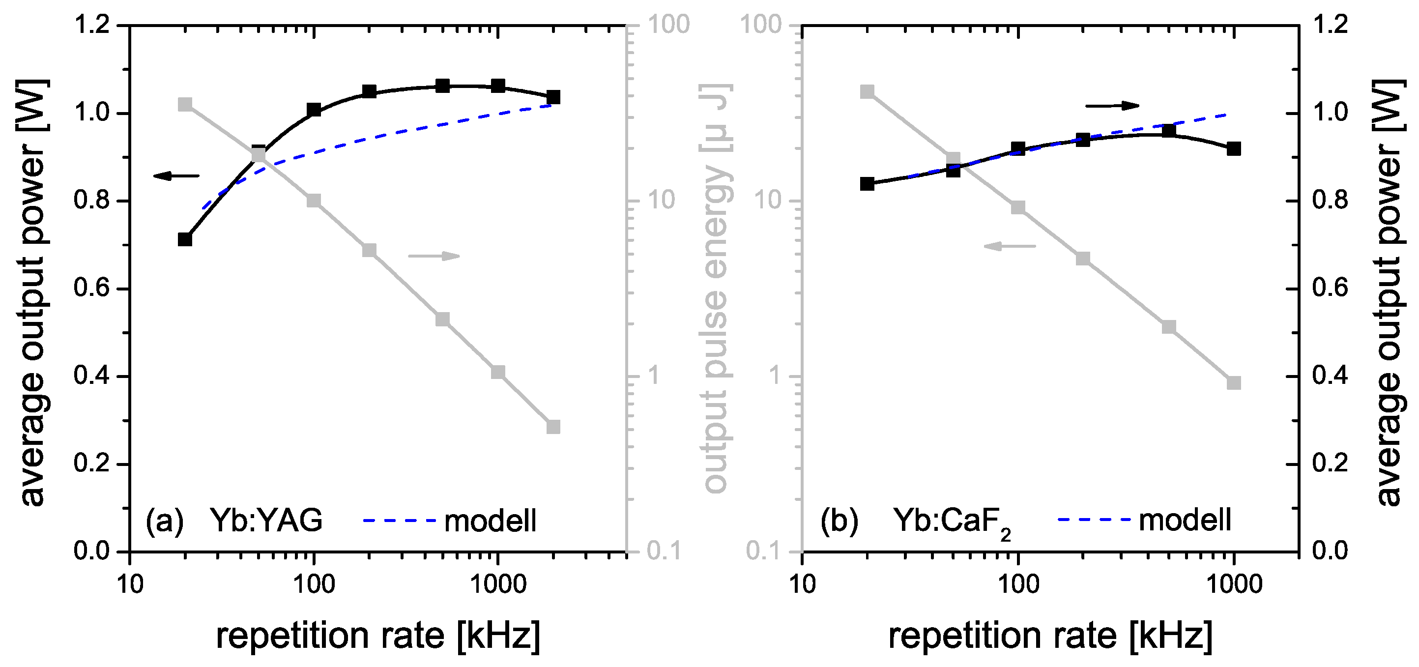
Figure 5.
Average output power and pulse energy vs. repetition rate at regenerative amplification for Yb:YAG (a) and Yb:CaF (b).
Figure 5.
Average output power and pulse energy vs. repetition rate at regenerative amplification for Yb:YAG (a) and Yb:CaF (b).
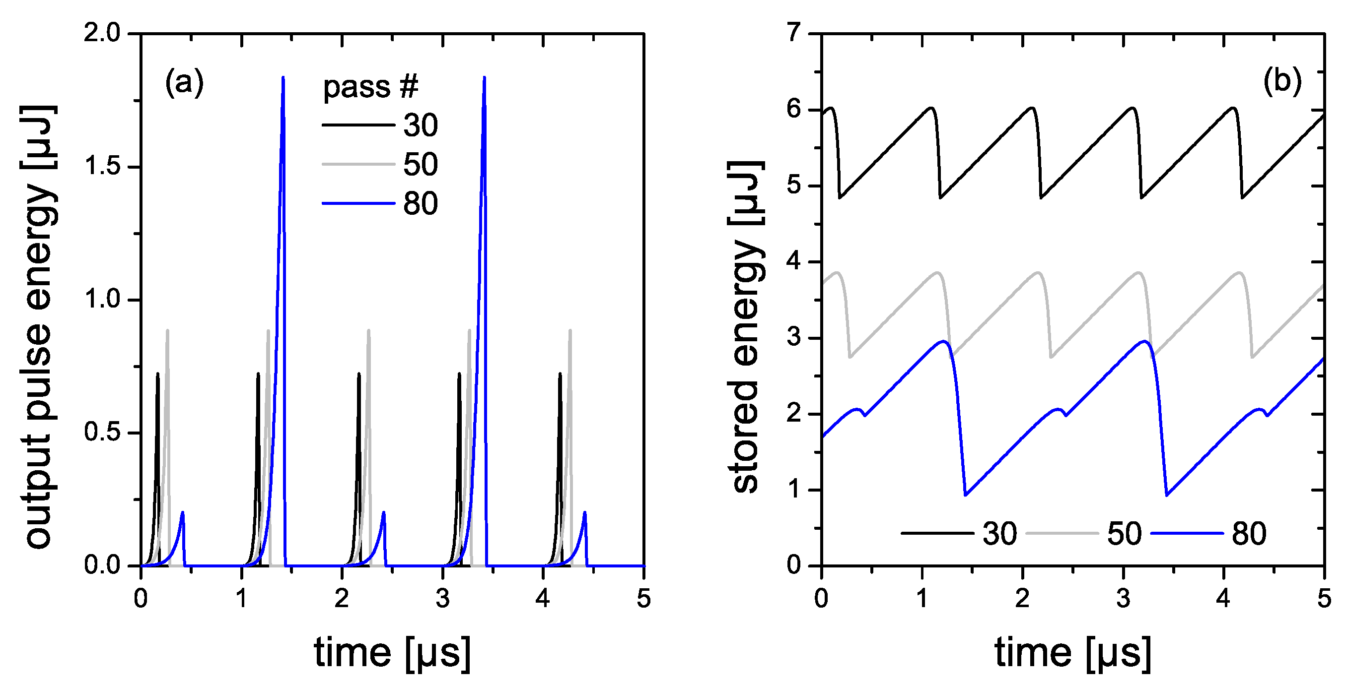
Figure 6.
Simulation of the rate equations in the case of Yb:CaF for a repetition rate of 1 MHz and continuous pumping at 8 W; output pulse energy (a) and stored energy within the gain medium (b) vs. time.
Figure 6.
Simulation of the rate equations in the case of Yb:CaF for a repetition rate of 1 MHz and continuous pumping at 8 W; output pulse energy (a) and stored energy within the gain medium (b) vs. time.
The intra-cavity and extra-cavity pulse trains at regenerative amplification are shown in
Figure 4. The number of round trips is set to 32 (Yb:YAG) and 40 (Yb:CaF
) to prevent instable pulse train operation such as period doubling or bifurcations at a repetition rate of 20 kHz. An optimum extraction of the output power is obtained at several 100 kHz which is shown in
Figure 5. In general, the extractable pulse energy is proportional to the inverse of the repetition rate with impact on the small-signal gain. We have also observed an increasing insensitivity [
19] of the output power against the variation of the pass number especially for very high repetition rates. This phenomenon can be explained by a numerical simulation (see
Table 1) of the rate equations [
20] while the results were normalized to a maximum average output power of 1 W at 1 MHz. In
Figure 6 the results in steady-state are illustrated for different numbers of round trips in the case of Yb:CaF
. At a pass number of 80 an instable pulse train operation becomes likely when operating close to gain depletion. A rising inversion level (stored energy) is obtained for a lower number of round trips while the total gain and therefore the cumulatively extracted power remains rather constant within a wider range. When modeling for repetition rates lower than 1 MHz we observe a drop of the average output power (see
Figure 5) depending on the fluorescence lifetime of the gain media, while the power would remain constant for an infinite fluorescence lifetime. The drop of the average output powers at high repetition rates can be explained by an increasing period required for mode-matching and spectral shaping after seeding especially due to a strongly reduced small signal gain.
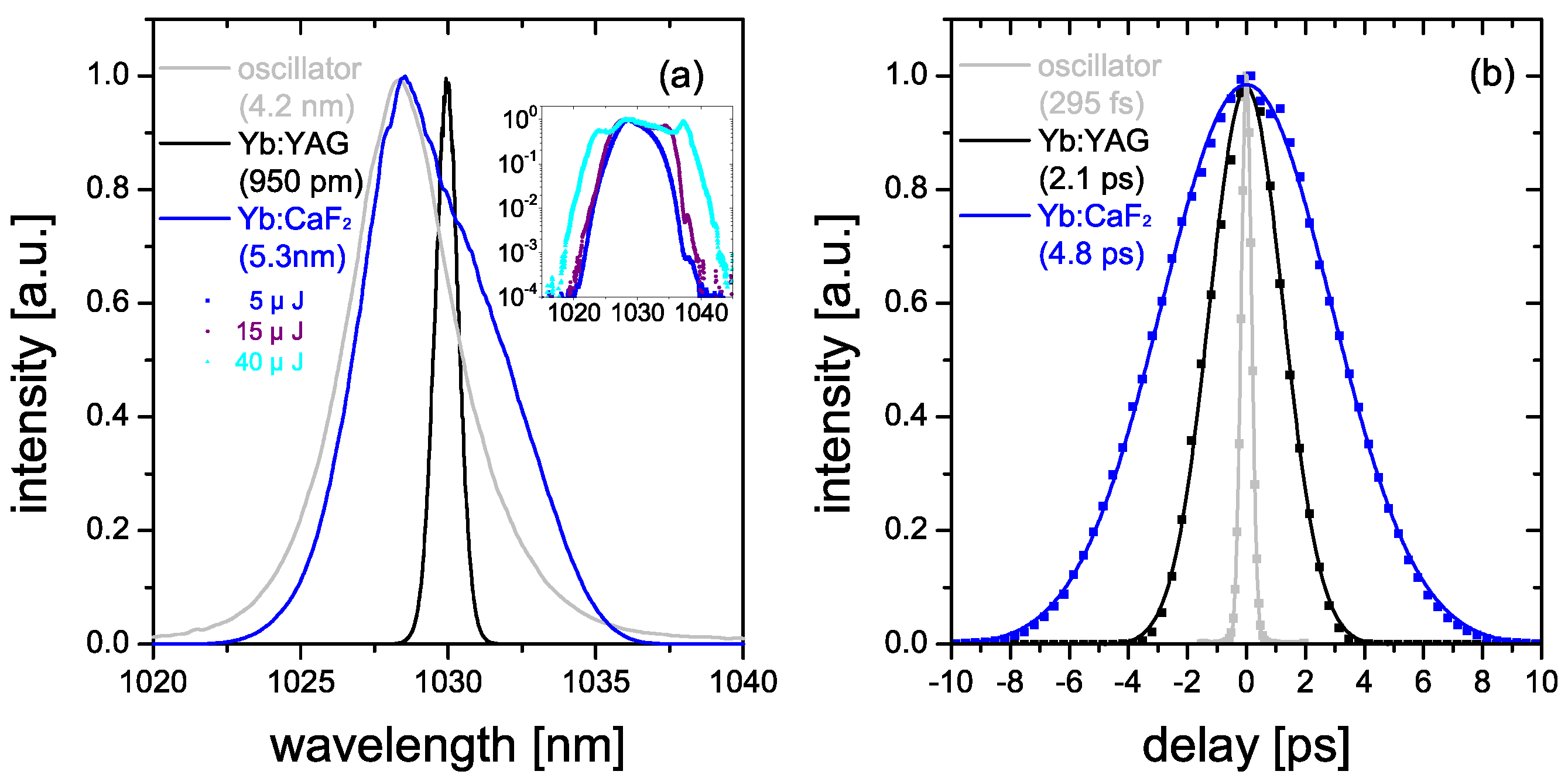
Figure 7.
Output pulse spectra (a) and intensity autocorrelation traces (b) for the fs-oscillator (gray), the regenerative Yb:YAG (black) and CaF (blue) amplifier, inset: spectra for Yb:CaF at different output pulse energy in logarithmic scale.
Figure 7.
Output pulse spectra (a) and intensity autocorrelation traces (b) for the fs-oscillator (gray), the regenerative Yb:YAG (black) and CaF (blue) amplifier, inset: spectra for Yb:CaF at different output pulse energy in logarithmic scale.
Figure 7 summarizes the output pulse spectra and the respective autocorrelation traces measured at a pulse energy of 5 μJ. Here, we used a scanning second-order intensity autocorrelator and an optical spectrum analyzer (Yokogawa AQ6370D, Yokogawa Meters & Instruments Corporation, Tokyo, Japan) with a resolution limit of 20 pm. The fs-oscillator with a time-bandwidth product (TBWP, normalized to bandwidth limitation) of 1.1 exhibits a sech
-shaped output spectrum with a bandwidth of 4.2 nm, and a pulse duration of 295 fs at full width at half maximum (FWHM). In the case of Yb:YAG we achieved a TBWP of 1.3 at a spectral width of 0.95 nm. We obtained a TBWP of 16.3 in the case of Yb:CaF
due to a broader bandwidth of 5.3 nm being more sensitive to dispersion. A group delay dispersion of 3750 fs
per pass including the gain medium, the Pockels cell and its BK7 windows can be given. We calculated a B-Integral of 0.2 for Yb:CaF
and 0.9 for Yb:YAG dominated by the intensity within the gain media considering a pulse energy of 5 μJ. In the case of Yb:CaF
spectral broadening up to 15 nm (FWHM) at 40 μJ was observed (see inset of
Figure 7a) while the beam-shape remained Gaussian.
A contrast level of better than 32 dB for picosecond pre-pulses including unpicked oscillator pulses as well as amplifier cavity leakages was measured with a photo-diode. When blocking the seed pulses we observed a nanosecond background level at −26 dB, while at amplifier operation the amplified spontaneous emission (ASE) is further suppressed.
Table 1.
Parameters used for regenerative amplifier modeling.
Table 1.
Parameters used for regenerative amplifier modeling.
| Parameter | Yb:YAG | Yb:CaF |
|---|
| Saturation fluence (1030 nm) | 10 J·cm | 95 J·cm |
| Fluorescence lifetime | 1 ms | 2.4 ms |
| Number of passes | 32 | 40 |
| Seed pulse energy | 0.6 nJ |
| Intra-cavity losses | 0.02 |


