Article

Double Relativistic Electron Accelerating Mirror

1
Max Born Institute für Nichtlineare Optik und Kurzzeitspektroskopie, 12489 Berlin, Max-Born-Straße 2 A, Germany
2
Vavilov State Optical Institute, 193232 St. Petersburg, Birzhevaya line 12, Russia
*
Author to whom correspondence should be addressed.
Appl. Sci. 2013, 3(1), 94-106; https://doi.org/10.3390/app3010094
Submission received: 19 November 2012 / Revised: 14 January 2013 / Accepted: 24 January 2013 / Published: 4 February 2013
(This article belongs to the Special Issue Ultraintense Ultrashort Pulse Lasers)

Abstract

:
In the present paper, the possibility of generation of thin dense relativistic electron layers is shown using the analytical and numerical modeling of laser pulse interaction with ultra-thin layers. It was shown that the maximum electron energy can be gained by optimal tuning between the target width, intensity and laser pulse duration. The optimal parameters were obtained from a self-consistent system of Maxwell equations and the equation of motion of electron layer. For thin relativistic electron layers, the gaining of maximum electron energies requires a second additional overdense plasma layer, thus cutting the laser radiation off the plasma screen at the instant of gaining the maximum energy (DREAM-schema).

1. Introduction

Generation of short-wavelength (less than the laser wavelength) dense relativistic electron bunches is of high interest for study and diagnostics of superfast physical processes. Such bunches make possible the direct electron microscopy, as well as the generation of short (atto-second range) pulses of soft X-ray and further X-ray microscopy. Short, harder X-ray pulses can be also generated during the scattering of additional laser pulses by the electron bunches. Generation of thin electron layers is possible using different methods, such as in a laser gas target, whereby the oscillations of nonlinear electron density occur leading to the generation of a sequence of thin electron layers [1,2]. Thin electron layers can be formed during the scattering of linear p-polarized intense laser pulse by a solid target [4]. Finally, the fast particle bunches can be generated during the interaction of intense laser pulse with nonuniform targets out of the target’s rear [5]; however, their width is much thicker and in the order of 100 nm. Compared to such alternatives, the usage of an ultra-thin grafene target [6,7,8], irradiated by circular-polarized pulse, has many advantages due to the fact that only one electron bunch is generated; the bunch charge achieves high magnitude (>1 nC) and the parameters (energy, width and particles number density) can be easily controlled by changing the laser intensity, pulse duration and layer width.
In the present work, the possibility of generation of thin dense relativistic electron layers is shown using the analytical and numerical modeling of the interaction of laser pulses with ultra-thin solid foils. The first ultrathin foil is semitransparent for laser radiation, but its electrons are removed by laser pulse and propagate together with them. The electric field of target ion core is much weaker than that of the laser one, thus movement of an electron bunch separated from the target can be described by the used self-consistent system of Maxwell equations and the electron equation of motion. The maximum electron energy can be gained by optimal tuning between the target width, intensity and laser pulse duration. The optimal parameters can be determined from our self-consistent system of Maxwell equations and the equation of motion of electron layer. For thin relativistic electron layers, the gaining of maximum electron energies requires an additional overdense plasma layer, which cuts the laser radiation off the plasma screen at the instant of gaining the maximum energy (Double Relativistic Electron Accelerating Mirror (DREAM) schema). The scattering of counter-propagating probe laser pulse by the generated relativistic electrons mirror makes possible the generation of the hard coherent electromagnetic radiation with quant energy of 1 keV and efficiency of 0.1% with respect to the energy of initial laser pulse generating the electron layer.

2. Theoretical Model

2.1. The Equation of Motion of Electron Layer

In the one-dimensional space approximation, and in the limit of zero electron layer width, it appears to be possible to integrate overcharge distribution in one-dimensional Liénard–Wiechert potentials, to express the Eigen-fields of the layer using its mechanical variables and, as a result, to write an equation for the dynamics including only the external field, velocity and layer coordinates. The radiation friction force (self-action) can also be expressed using the layer velocity. It is convenient to write the equation of layer motion using the dimensionless parameters Applsci 03 00094 i001 
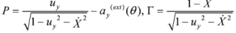
and being the constants of motion for a single electron in an electromagnetic wave down, where as ay(ext) = |e|Ay(ext)(θ)/mec2 is a dimensionless vector potential representing the incident wave; θ= ωt - kx, uy = vy / c is the dimensionless layer velocity component along the polarization direction (у); and, Applsci 03 00094 i002 is the dimensionless layer velocity component along the wave vector (х). The equation of motion of the thin electron layer using these variables has the following form:
Applsci 03 00094 i003
where τ = ωt, X = ωx/c are the dimensionless time and coordinate of the layer, and the dimensionless parameter ε0 = πnelf/ncrλL defines both the width lf and the electron layer number density ne. The equations of motion (1) correspond to the equations of motion of an extended electron layer [6] if one makes a transition lf→0 in the latter equations and considers the movement of the central region of the layer.
Let the electron layer be still at the initial instant: P(0) = 0, Γ(0) = 1,ay(ext)(0) = 0, X(0) = 0, τ(0) = 0. Then, let the electron layer be acted upon by a pulse of limited duration ay(ext)(θ) = a0 sin(θ), θ ∈ [0; 2πN], which is switched off after N cycles. Let us define the finite electron energy at θ= 2πN,i.e., at the time moment of pulse switching-off. This energy (Lorentz factor) can be expressed through the variables P, Γ in the following way:
Applsci 03 00094 i004
In a case for ε0 = 0, when P = 0, Γ = 1, these equations let us obtain the energy of a single electron in a linearly polarized wave [9]. At the instant of pulse switching-off θ = 2πN, the initial single electron energy remains the same and no energy exchange between the electron and pulse occurs. Let us find the solution of the system of Equation (1) and consider the case close to the experiment parameters of the laser pulse a0 = 10, N = 10. The dependence of the layer energy at the instant of pulse switching-off is shown in Figure 1.
Figure 1. The dependence of the layer energy on its width at the instant of pulse switching-off.
Applsci 03 00094 g001
When ε0 = 0, the layer energy can be determined from Equation (2). As one can clearly see, during an increase of ε0, the layer starts to speed up and its energy begins to increase in comparison with the energy of a single electron. When ε0 = 0.02, the target electrons speed up until the energy, which is significantly higher than the energy of a single electron, is obtained in the wave. During the pulse action period, the maximum energy oscillates and the Lorentz factor gains the magnitude 1000. At a fixed value of a0, when the target width increases further, the layer stops to speed up and its energy begins to oscillate in time with the same amplitudes. Hence, the equations for the layer motion demonstrate that there is an optimum width for acceleration, and that the instantaneous layer energy during the laser pulse action period can be significantly higher than that when the pulse is switched off. This is why, when solving the acceleration optimization problem, it is reasonable to terminate the pulse action at the instant of the maximum gained energy. As will be shown, this can be done either by settling an additional plasma layer cutting the laser field off the electrons. It is noteworthy that the following formula for the angle of electron layer propagation (with respect to the axis x) out of the laser field is valid
Applsci 03 00094 i005
Let us determine the optimal width of the electron layer for maximum energy gain. Target width should be thicker than 0.1 nm (one-atomic layer) and ne / ncr > 100 for solid targets that is why the lower limit should be ε0 ≈ 0.04. In order for such a target to gain the energy of 1 GeV, it is sufficient to have a pulse with a0 = 19 and duration 5 laser periods. At laser wavelength 0.8 μm, the corresponding intensity becomes 8 × 10²⁰ W/cm2. In order to tune the electron energy peak to the pulse end, one needs to alter the pulse duration and slightly changes ε0. For example, for the pulse intensity 2 × 10²¹ W/cm2 (а0 = 30) and duration of exactly 4 periods the target with ε0 = 0.042 gains a maximum energy of 2.06 GeV, and the energy becomes 1.8 GeV at the end of the 4th period, i.e. close to the maximum one. However, if one slightly changes ε0, for example, to 0.05, then the takeoff energy drops to only 306 MeV. Hence, the electron energy peak related to the end of the laser pulse exhibits a resonance character and its optimization requires the exact tuning of all parameters. It is significant that the high takeoff electron energies can be gained through the abrupt switching-off of the laser pulse. If one considers the major (during 2 and 4 periods) switching-off of the laser pulse, then the takeoff energies are one order lower than the maximum one. Real laser pulses, unless special technical tricks are employed, have the time growth and drop-off of the order of several periods and these times are not determined with high accuracy, i.e., a fraction of the periods. Consequently, in a real experiment, it is rather impossible to get the resonance tuning to the maximum layer energy after the interaction. Let us outline that dynamic Equation (1) were obtained in the approximation of a thin (in comparison with the laser wavelength) electron layer and do not take into account its broadening by Coulomb repulsion, which was done in [8]. Using the formulas of this paper, we have shown that our approximation of thin layer is valid until the instant of probe radiation scattering off electron mirror. The reflection coefficient of such a mirror depends only on electron surface density as ne(t)lf(t) ≈ ne(0)lf(0) does not change during Coulomb repulsion. We were subsequently able to calculate electron layer thickness within an appropriate accuracy.

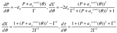
2.2. The Influence of a Second Plasma Layer on the Parameters of the Accelerated Electrons

However, there is the possibility of conserving the maximum layer energy locally in time by settling at some point a second foil, which would cut off the laser field and would conserve the maximum layer energy [10,11]. Let us determine from Equation (1) this position and the laboratory time interval during which this energy can be gained. Solution γ(X) of the system has the following form, shown in Figure 2.
Figure 2. The dependence of the layer energy on its longitudinal coordinates at a0 = 19, linear polarization, pulse duration = five periods and ε0 = 0.04.
Applsci 03 00094 g002
In Figure 2, the spatial stretching-out of the electron energy peak is quite reasonable, thereby explaining why there is no necessity for the exact determination of the plasma screen position at high intensities and layer energies. The dimensionless coordinate X = ωx / c = 2πx / λL. Hence, X ≈ 5·104 corresponds to x/λL =7960 or х = 6.4 mm. It is sufficient to determine the mirror position to approximately mm accuracy. The layer takeoff angle (3) at such energy is only 0.1°. As a result, the plasma screen enables us to fix the local temporal maximum layer energy.
We would like to point out that the target optimization with respect to ε0 for the maximum electron energy gain in the layer in its turn will not be optimal for the whole maximum layer energy, i.e., γε0 If one increases ε0, then this value increases as well, reaching its maximum at ε0≈ 0.1 before dropping; the energy of a single electron corresponding to the maximum layer energy being then 558 MeV instead of 1 GeV. Hence, the optimal target with respect to the layer energy is two times thicker than that being optimal with respect to γ, and the electron energy is two times lower. In addition, we would like to point out that the maximum layer energy with respect to ε0 is quite smooth, but γ depends on ε0 more.
For circular polarization, the equations for the z-components of laser field and electron momentum should be added to the system (1). The solution of the new, but similar, system is shown in Figure 3. Here, one can see the dynamics of electron acceleration of the same foil by laser pulses of the same intensity but different polarization. One can see that the layer (initially at rest) energy is oscillating for both polarizations. For the linear polarization, the number of oscillations is equal to the number of semi-periods of laser pulse and is connected to double frequency of laser ponderomotive pressure. However, for the circular polarization, the number of oscillation is equal to the number of pulse periods. In the case of the circular polarization, maximal energy is higher and the electron layer can propagate at a longer distance compared to the linear one. The spatial domain of maximal energy for the circular polarization is wider, thus the requirements for the positioning of the second plasma mirror are lower.
Figure 3. The dependence of the layer’s energy on its longitudinal coordinate. The red color denotes the linear polarization case at α0 = 23 and ε0 = 0.02; the blue color denotes the circular polarization case at Applsci 03 00094 i006 
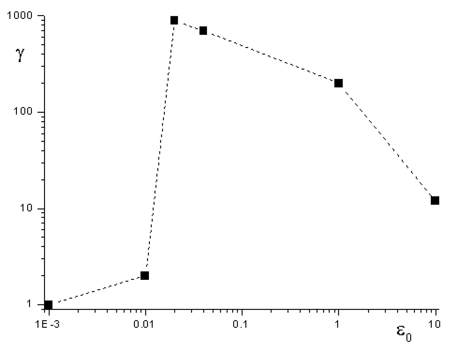
and ε0 = 0.02. Pulse duration is four laser periods for both cases.
Applsci 03 00094 g003
The selection of a target material (atomic number) has influence on initial electron density, i.e., the parameter ε0. Now the manufacturing of foils of sub-nanometer size (up to 0.5 nm) is possible only for carbon (Grafen) and plastic targets. We therefore consider, in our numerical modeling, fully ionized carbon targets.

3. Results and Discussion

3.1. 2D Numerical Modeling of the Electron and Plasma Layers Interaction

Let us consider the propagation of the electron bunch through the plasma layer using numerical modeling by the modified code [12]. In the calculations, the laser pulse of intensity 102° W/cm2, duration 15 fs and diameter of 7 μm, interacts with two sequentially located С+6 targets having an ion number density of 1023 cm−3. The width of the first target was 5 nm, representing an electron layer source, the second being 1 μm, thus representing the screen cutting off the laser pulse; the distance between targets was 11 μm. The numerical step was 1 nm; 40 particles were allocated in the cell.
In Figure 4 the black color illustrates the initial location of targets, and the red color is the spatial distribution of fast electrons (>10 MeV) at the time t = 35 fs (before the second target is reached). One can see that the relativistic electron layer has been generated. The plane cross section at y = 9 μm shows that the electron bunch number density is 0.06 of the initial one 1023 cm−3, i.e., overcritical. The cut-off energy of the calculated electron distribution function exceeds the energy of a single electron in the field of plane EM. wave (γ = 1 + α2 / 2, [9]). For а = 8.5 we have γ = 38, corresponding to the energy of ~20 MeV. In the simulations, one can easily see the cut-off at 28 MeV, which can be explained by the difference of the field amplitude from that in a vacuum during laser pulse penetration through the target. Such self-consisted field behavior is taken into account by the system (1). The calculated field shows that the amplitude was increased by 1.2 times. Estimation of the energy from the formula (2) demonstrates increase of electron energy up to 30 MeV, which correlates with the calculated value –28 MeV. When the laser pulse reaches the second target, the characteristic energy of new, generated in this target fast electrons, (with Applsci 03 00094 i007 
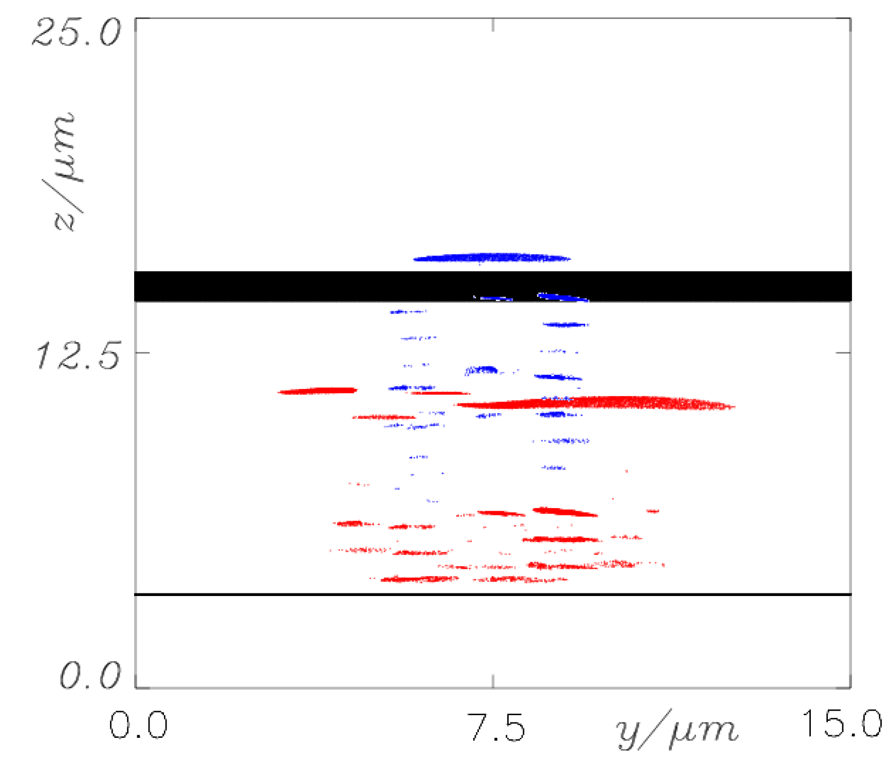
) becomes ~4 MeV, correspondingly, the “tail” of the electron distribution function from the first target should not significantly change when passing through the second target. In Figure 4, the blue color illustrates the electron number density (with electrons energy > 15 MeV) at the time t = 57 fs when the electron layer from the first target reaches the second one. One can clearly see that the electron bunch has passed through the second target without any loss of energy and number of electrons. The laser pulse appears to be cut off by the dense plasma with 0.1 μm width. Thus, the plasma layer enables us to effectively separate the thin relativistic electron layer from the laser pulse without any loss of energy or number of electrons. It is noteworthy that the thickness of the electron bunch after propagation for the distance of 11 microns is about 60 nm in accordance with our calculations and estimations [8]. It is larger compared to the initial thickness, but is, in any case, still less than the laser wavelength.
Figure 4. The spatial distributions of all electrons at time t = 0fs (black color) and fast electrons (>10 MeV) at t = 35 fs (before the second target is reached, red color) and at t = 57 fs (blue color) when the electron layer from the first target has reached the second one.
Applsci 03 00094 g004

3.2. Scattering of a Counter-Propagating Laser Pulse from the Relativistic Electron Mirror

The generated stable thin relativistic electron layer can be used as a source of coherent hard radiation produced by scattering of a counter-propagating laser pulse by the electron layer (see examples in [13,14]). Simple estimations indicate that in the rest frame of reference of a moving layer, the frequency of an incident pulse gets increased by the factor Applsci 03 00094 i008 times. The scattering in the rest frame of reference occurs without frequency change. The following recalculation of the frequency of scattered radiation in the original laboratory frame of reference gives again the factor 2γx so that the reflected pulse has a quantum energy Applsci 03 00094 i009 , with ωs being the frequency of the incident counter-propagating laser pulse. Note that a frequency shift is appearing not only due to Doppler’s effect of radiation reflected off a moving overdense electron layer, but also due to change of electron density inside a layer [14]. In our case, the number of electrons at laser front does not change after propagation out of the second target, and the effect connected with change of electron density is absent during the process of counter-propagating laser pulse reflection.
In order to estimate the reflection coefficient of the thin relativistic electron layer we would like to make use of the well-known Fresnel reflection coefficient of the thin relativistic layer of a still plasma R΄ = ε0΄2 / (ε0΄2 + 1) [15]. The surface electron number density ne΄lf΄ contained in ε0´ (see definition of ε0 in Equation (2)) does not depend on the type of a reference system, which is why ne΄lf΄ = nelf. Except for ne΄lf΄, the denominator of ε0´ ontains only the frequency of the incident pulse ωL΄, which in the rest frame of reference of the electron layer is equal to Applsci 03 00094 i010 [9]. As a result, in the rest frame of reference of the electron layer, the reflection coefficient expressed using the variables in the laboratory frame of reference is equal to Applsci 03 00094 i011 . In the rest frame of reference of the layer, the reflection occurs without frequency change, thus explaining why the number of reflected quanta Nh (hard quanta in the laboratory frame of reference) can be expressed through the number of incident laser quanta Ns as following Nh = R´NS. Since the absolute numbers of quanta are the relativistic invariants, then R´ is also the reflection coefficient with respect to the number of quanta (but not with respect to the pulses energies) in laboratory frame of reference. We would like to emphasize that the reflection coefficient R´ implies the non-relativistic (<1018 W/cm2) intensity Is´ of the incident radiation in the rest frame of reference of the layer. In the opposite case, as it was shown in [15], the decrease of the reflection coefficient occurs by Is´ / 1018 W/cm2 times (a more detailed and complex formula for R΄(ε0΄, IL΄)is given in this paper). The employment of the coefficient from the equation for the reflection coefficient R also implies the coherent character of the scattering process (this also follows from the fact that Applsci 03 00094 i012 , i.e., the squared number of electrons in the layer) and the assumption of thinness of the layer (the width is less than the wavelength in the rest frame of reference). In order to validate these approximations, one needs to satisfy the inequality Applsci 03 00094 i013 for the electron number density of the thin layer at the instant of reflection. In the numerical modeling, results of which are presented in Figure 5, the electron number density in the layer at t = 57 fs was estimated to 6 × 1021 cm−3, and this inequality was valid for the whole spectrum of electron energy. If, for some reason (e.g. durable movement of the electron layer), the electron number density will be low Applsci 03 00094 i014 , then the coherent scattering will switch to the non-coherent Thomson scattering by single electrons. In this case, it is obvious that Applsci 03 00094 i015 , where S is the scattering spot area, and σT = 6.6 × 10⁻²⁵ cm2 is Thomson scattering cross-section. The reflection coefficient of non-coherent scattering is obviously equal to RT = σTnelf and its absolute magnitudes is substantially lower than R. The main important characteristic of the hard radiation source is its luminosity B (number of photons radiated from unit area per unit solid angle and per unit time). When the laser pulse is repeatedly irradiated with the frequency f (for the considered laser tens of Hz) the average flow (number of quanta per unit time) of the hard radiation will be Φ = fRNs. The average luminosity B of forward in the layer movement direction radiation is related to the flow Ф through the following relation:
Applsci 03 00094 i016
In the paper [13], instead of the average luminosity (4) one considers the peak luminosity Bmaxduring the scattering time τs / 4γx2 (during the scattering the number of pulse periods remains constant) of a single laser pulse of duration τs. This luminosity differs in the definition of the flow of hard quanta as Φmax= 4γx2RNS / τS and is 4γx2(s)-1 times higher than the average one (4). Further, in our numerical modeling, using Equation (3), we will make estimations of the average and peak luminosities of a source of hard quanta. The presented estimates of the reflection coefficient of the relativistic electron layer do not take into account some important physical effects occurring during scattering, such as the smearing of the electrical charge and slowing down of electrons by the counter-propagating pulse. For more accurate calculations of the energy of a reflected quantum and the reflection coefficient, the one-dimensional PIC simulations of reflection of a 1018 W/cm2 intense and 16 fs long laser pulse off the thin electron layer have been carried out; the layer was generated out of 0.6 nm thick C+6 target irradiated by a 5 × 10¹⁹ W/cm2 intense and 16 fs long laser pulse. In Figure 5a, the pulse fields and electron layer number density (red) before the interaction are shown. The main pulse (blue) propagates from left to right, the counter (black)—in the opposite direction.
Figure 5. The fields of the main (blue) and counter-propagating (black) pulses, the electrical number density of the thin layer (red) (a) before the scattering from the counter-propagating pulse (20 fs); (b)at the instant of pulses overlap (35 fs) and (c) after the formation of the reflected hard pulse (50 fs).
Applsci 03 00094 g005
During the movement of the electron layer in a superimposed field of two counter-propagating laser pulses of different amplitudes, the intense smearing of electron density occurs, which is clearly seen in Figure 5b. In the same figure, the small part of the counter-propagating pulse reflected off the electron front and propagating onto the front from left to right can be seen. In Figure 5b, the field of reflected pulse is shown the next time in a magnified scale, i.e., when the reflected pulse has overtaken the relativistic electrons. For determination of the reflection coefficient R, frequency Ω (in the initial frequency ωsunits) of scattered radiation and determination of their dependences on the width of the initial target and initial pulse intensity, similar calculations have been made for intensities of 5 × 10¹⁸, 1020, 5 × 10²⁰ W/cm2 and target widths of 0.4, 1, 5, 10 nm. The counter-propagating pulse had the same intensity, 1018 W/cm2.
The results of the calculations are presented in the Figure 6 as the functions R(I,lf), Ω(I,lf). These figures show that for generation of hard quanta (Ω >100) the thin laser targets < 1 nm and high intensity laser targets > 1020 W/cm2 are optimal. However, the reflection coefficient of the test pulse is small and amounts to only a small percentage. The reflection coefficient R enables us to determine the conversion coefficient χ of laser energy εLof the main pulse to the energy of hard radiation χ= ΩS / εL, where εsis the energy of reflected pulse. The contrary behavior of dependences of the reflection coefficient and hard quanta energy on the laser intensity and target width shown in Figure 6 indicates the existence of an optimum with respect to the width and intensity at which the conversion coefficient of laser radiation energy to the energy of hard radiation reaches its maximum. In Figure 7, the dependence of the energy conversion coefficient of the main laser pulse to the hard quanta on the laser intensity is shown.
Figure 6. The dependence of the frequency Ω (a) of scattered hard radiation and the reflection coefficient R on the intensity of the main laser pulse. The target width is 0.6 nm. The dependence of the frequency Ω (b) of scattered hard radiation R and the reflection coefficient on the width of initial target at laser intensity of 5 × 10¹⁹ W/cm2.
Applsci 03 00094 g006
Figure 7. The dependence of the energy conversion coefficient of the main laser pulse to the hard quanta on the laser intensity at 0.6 nm target width.
Applsci 03 00094 g007
One can clearly see that the optimal conversion can be reached at comparatively low energies of hard quanta 50 eV (Ω ≈ 30), which is why, in our case, the generation of hard quanta of high energies (higher than 1 keV) occurs at the non-optimal coefficient of energy conversion to that of the scattered radiation. In our calculations, at an intensity of 5 × 10¹⁹ W/cm2 and width of Carbon target of 0.6 nm, the conversion coefficient is χ ≈ 0.1%. Such a conversion coefficient exceeds that of laser X-ray line conversion in the same spectrum of quanta energies. Let us estimate, using Equation (3), the source luminosity corresponding to the parameters of Figure 5. The number of photons per unit area Ns/S for a given laser pulse (16 fs, 1018 W/cm2, 0.8 μm) amounts to 5.3 × 10²⁰ photons/mm2. In accordance with Figure 6a, the reflection coefficient is R≈ 0.05 and the value Ω = 4 rx2≈ 40. At the scattering pulse repetition rate f = 10 Hz, the average luminosity is about 1.3 × 10¹⁵ photons/(sec mm2 mrad2). This is significantly higher than that of conventional X-ray tubes (108) and laser-electron generators on a base of accelerators (1012), but lower than the average luminosity of contemporary synchrotrons (1021) in the approximate energy range of hard quanta. In Figure 5, the magnitude of the source peak luminosity reaches 3 × 1029 photons/(sec mm2 mrad2), which is 8 orders higher than that of synchrotron luminosity. One can increase average luminosity by increasing the pulse repetition rate to 10 kHz, thereby leading to a doubling of the average luminosity of such a scheme.

4. Conclusions

Concluding the above results, the relativistic intense laser pulse enables us to form a relativistic dense and thin electron layer when interacting with the ultrathin target. Optimum foil thickness for layer production is much smaller than targets for fast ion generation and the optimal parameter ε0 = πnelf / ncrλ depends not only on intensity, but also on duration of laser pulse. For a laser pulse of length of about 10 laser periods, the thickness ε0 ≈ 0.01 can be optimal. At the instant of termination of a laser pulse the electron energy in a layer does not come back to its initial value in an optimum range of thickness. Therefore, the plasma screening for an optimum target ceases to be necessary. At the same time, final magnitude of energy of a layer can be less than maximum possible magnitude reached during the pulse action. Then, by means of the plasma screening (DREAM scheme), it is possible to fix the maximum value. Because energy of a layer’s maximum is considerably extended in the spatial area, there is therefore no necessity for high accuracy for the screen positioning. Maximum energy in the case of the circular polarization is higher, and electron layer can propagate for a longer distance compared to the linear one. The spatial domain of maximum energy for the circular polarization is wider, thus the requirements for the location of secondary plasma mirror are lower. Reflection of a counter-propagating laser pulse off the relativistic mirror, produced by the main pulse in DREAM scheme, enables the production of KeV coherent radiation with an efficiency of about 0.1% in respect to the energy of the main laser pulse. Peak brightness of a source of the hard quanta gained in DREAM scheme exceeds that of known sources of hard radiation, and average brightness exceeds that of X-ray tubes and laser-electron generators, but it is less than that of a synchrotron X-ray source.

Acknowledgment

A. A. Andreev acknowledges the provided computation resources of JSC at project HBUIS.

Conflict of Interest

The authors declare no conflict of interest.

References

  1. Bulanov, S.; Esirkepov, T.; Tajima, T. Light Intensification towards the Schwinger Limit. Phys. Rev. Lett. 2003, 91, 085001–085004. [Google Scholar]
  2. Pirozhkov, A.S.; Kando, J.; Ma, M.; Esirkepov, T.Z.; Fukuda, Y.; Chen, L.-M.; Daito, I.; Ogura, K.; Homma, T.; Hayashi, Y.; et al. Frequency multiplication of light back-reflected from a relativistic wake wave. Phys. Plasmas 2007, 14, 123106-1–123106-22. [Google Scholar] [CrossRef]
  3. Naumova, N.; Nees, J.A.; Sokolov, I.V.; Hou, B.; Mourou, G.A. Relativistic Generation of Isolated Attosecond Pulses in a λ3Focal Volume. Phys. Rev. Lett. 2004, 92, 063902–063904. [Google Scholar]
  4. Andreev, A. Generation of Ultrashort Electron Bunches from Overdense Mass Limited Target. In Proceedings of International Conference ICONO-LAT, St.Petersburg, Russia, 30 June 2005.
  5. Andreev, A.; Sonobe, R.; Kawata, S.; Miyazaki, S.; Sakai, K.; Miyauchi, K.; Kikuchi, T.; Platonov, K.; Nemoto, K. Effect of a laser prepulse on fast ion generation in the interaction of ultra-short intense laser pulses with a limited-mass foil target. Plasma Phys. Control. Fusion 2006, 48, 1605–1619. [Google Scholar]
  6. Kulagin, V.V.; Cherepenin, V.A.; Hur, M.S.; Suk, H. Flying mirror model for interaction of a super-intense nonadiabatic laser pulse with a thin plasma layer: Dynamics of electrons in a linearly polarized external field. Phys. Plasmas 2007, 14, 113101-1–113101-10. [Google Scholar]
  7. Kulagin, V.V.; Cherepenin, V.A.; Hur, M.S.; Suk, H. Theoretical Investigation of Controlled Generation of a Dense Attosecond Relativistic Electron Bunch from the Interaction of an Ultrashort Laser Pulse with a Nanofilm. Phys. Rev. Lett. 2007, 99, 124801-1–124801-4. [Google Scholar]
  8. Kulagin, V.V.; Cherepenin, V.A.; Hur, M.S.; Gulyaev, Y.V.; Kornienko, V.N.; Pae, K.H.; Valuev, V.V.; Lee, J.; Suk, H. Characteristics of relativistic electron mirrors generated by an ultrashort non adiabatic laser pulse from a nanofilm. Phys. Rev. E 2009, 80, 016404-1–016404-12. [Google Scholar]
  9. Landau, L.D. The Classical Theory of Fields, 4th ed; Butterworth-Heinemann: Oxford, UK, 1975; Volume 2, pp. 91–99. [Google Scholar]
  10. Miyauchi, K.; Miyazaki, S.; Sakai, K.; Kawata, S.; Kong, Q.; Andreev, A.A.; Kikuchi, T. Laser electron acceleration by a plasma separator. Phys. Plasmas 2004, 11, 4878–4881. [Google Scholar] [CrossRef]
  11. Wu, H.-C.; Meyer-ter-Vehn, J.; Fernandez, J.; Hegelich, B.M. Uniform Laser-Driven Relativistic Electron Layer for Coherent Thomson Scattering. Phys. Rev. Lett. 2010, 104, 23481–23484. [Google Scholar]
  12. Kemp, A.; Ruhl, H. Multispecies ion acceleration off laser-irradiated water droplets. Phys. Plasmas 2005, 12, 033105-1–033105-10. [Google Scholar]
  13. Esirkepov, T.Z.; Bulanov, S.V.; Kando, M.; Pirozhkov, A.S.; Zhidkov, A.G. Boosted high-harmonics pulse from double-sided relativistic mirror. Phys. Rev. Lett. 2009, 103, 025002-1–025002-4. [Google Scholar]
  14. Dias, J.M.; Lopes, N.C.; Silva, L.O.; Figueira, G.; Mendonca, T. Two-dimensional collision of probe photons with relativistic ionization fronts. Phys. Rev. E 2002, 65, 036404-1–036404-5. [Google Scholar] [CrossRef]
  15. Andreev, A.A.; Steinke, S.; Schnuerer, M.; Henig, A.; Nickles, P.V.; Platonov, K.Y.; Sokollik, T.; Sandner, W. Hybrid ion acceleration with ultrathin composite foils irradiated by high intensity circularly-polarized laser light. Phys. Plasmas 2010, 17, 123111-1–123111-11. [Google Scholar]

