1. Introduction
Due to the problem of global warming, utilization of distributed generation systems, which are connected with a distribution grid system, has been of interest and has received considerable attention in recent years. As the distributed generation can be located close to load consumers, it can have some merits: increasing the available power, improving the overall system reliability, lowering cost, reducing emissions and expanding energy options [
1]. It is well known that wind power is one of the distributed resources. However, connecting wind turbine generators to a distribution grid system leads to stability problems due to the output power fluctuation. Therefore, it is very important to analyze a suitable control system for wind generators connected to the grid.
The wind turbines can be Fixed Speed Wind Turbines with Induction Generator (FSWT-IG) or Variable Speed Wind Turbines with Permanent Magnet Synchronous Generator (VSWT-PMSG). The FSWT-IG has the advantages of mechanical simplicity, low specific mass, robust construction, and cost efficiency [
2]. However, its disadvantages are a limited ability for power quality control and terminal voltage fluctuation under steady state condition, due to the uncontrollable reactive power consumption [
3]. The VSWT-PMSG is a promising and attractive type of wind turbine concept, in which PMSG can be directly driven by a wind turbine and is connected to the power grid system through the AC/DC/AC power converter. The advantages of VSWT-PMSG are: (1) No gearbox and no brushes, and thus higher reliability; (2) No additional power supply for excitation; (3) The converter permits very flexible control of active and reactive power in cases of normal and disturbed grid conditions [
4,
5]. Therefore, a combined installation of VSWT-PMSG and FSWT-IG in a wind farm can be efficient due to reduced system investment cost. However, the PMSG has a more complex generator construction and more complicated controller system compared with FSWT-IG. Hence, the design and analysis of the power converter controller system still needs to be improved.
The AC/DC/AC converter of PMSG consists of a stator side converter and a grid side converter linked by dc circuit. The grid side converter has an important role in ensuring the active and reactive power delivered to the network effectively. Parameter change in the grid system can lead to a significant impact on the stability of the control system performance, especially under fault conditions. The deviation of grid system impedances can cause change in the stability gain margin and phase margin of the control system. In addition, the converter is operated at high switching frequencies between 2–15 kHz resulting in high order harmonics, which can disturb sensitive load on the grid and generate power losses [
6,
7]. To reduce harmonic currents injected to the grid, LC filter is an attractive solution because of its many potential advantages, such as higher harmonic attenuation and smaller inductances compared with an L filter [
8]. However, the resonance frequency of the filter can cause stability problems in the control system performance. Hence, determination of gain parameters should be performed carefully in the design process.
Traditionally, the conventional PI controller is a very common in the control of the power converter of PMSG because of its simple structure and good performance in a wide range of operating conditions. PI controllers are simple but can not always effectively control systems with changing parameters or strong nonlinearities, and they may need frequent online retuning of their parameters [
9]. Integration of a fuzzy logic control with a conventional PI controller could be an effective way to solve the problem of system parameter change. The fuzzy logic control can be used to adjust the gain parameters of the PI controller for any operating conditions. Hence, a good control performance can be achieved. However, the membership function of the fuzzy set should be carefully determined in the controller design. It is difficult to achieve an optimal controller performance by using a trial and error method.
Based on the view above, design fuzzy logic controller for the grid side converter of PMSG is proposed, in order to enhance the dynamic stability of a small wind farm including FSWT-IG connected to a grid system. To reduce harmonics injected into the grid, the installation of an LC filter is also considered.
Section 2 describes VSWT- PMSG and LC filter models used in this study.
Section 3 describes the control system of VSWT-PMSG.
Section 4 describes a new design method of a fuzzy logic controller for PMSG.
Section 5 describes the simulation results in transient and steady state conditions. Finally,
Section 6 presents some conclusions regarding this work.
3. The VSWT-PMSG Control System
The block diagram of control system for VSWT-PMSG proposed in this paper is shown in
Figure 6. The VSWT-PMSG system consists of the following components: a direct drive PMSG, blade pitch controller, AC/DC/AC converters based on two levels of IGBT which are composed of stator side converter (SSC) and grid side converter (GSC), a DC-link circuit composed of a chopper with a resistance (
Rc) and a capacitor (
Cdc), two voltage source converter controllers (stator side controller and grid side controller), and LC filter with passive damping resistance.
Figure 6.
VSWT-PMSG control system.
Figure 6.
VSWT-PMSG control system.
The SSC is connected to the stator of PMSG, and it converts the three-phase AC voltage generated by PMSG to DC voltage. The three-phase voltage and current of PMSG are detected on the stator terminal. The rotor speed of PMSG is detected from the rotor of the generator. All outputs of the sensors are fed to the stator side controller as input signals in order to control the voltage references of the stator side converter for modulation.
In the GSC, the converter converts the DC voltage into the three-phase AC voltage of the grid frequency. The converter is connected to the grid system through an LC filter and a step up transformer. The grid current and the grid voltage sensors are detected on the converter side of the LC filter and the high voltage side of the transformer, respectively. The DC voltage (Vdc) is detected on the DC capacitor. Using the grid side controller controls the voltage reference of grid side voltage source converter for modulation. When a fault occurs in the grid, the Vdc increases significantly due to power unbalance between SSC and GSC. In order to protect the DC-link circuit, the controller activates the chopper by a trigger command (Ctrl).
Output power of a wind generator always fluctuates due to the wind speed variations. To maintain the output power of generator under the rated level, a pitch controller is used to regulate rotational speed of PMSG under its rated value.
In modulation technique, Third Harmonic Injection Pulse Wave Modulation (THIPWM) is used in this work. Injection of the third harmonic in the reference voltage makes it possible to utilize the voltage reference without over modulation. In addition, the THIPWM can maximize fundamental amplitude of the output voltage [
14].
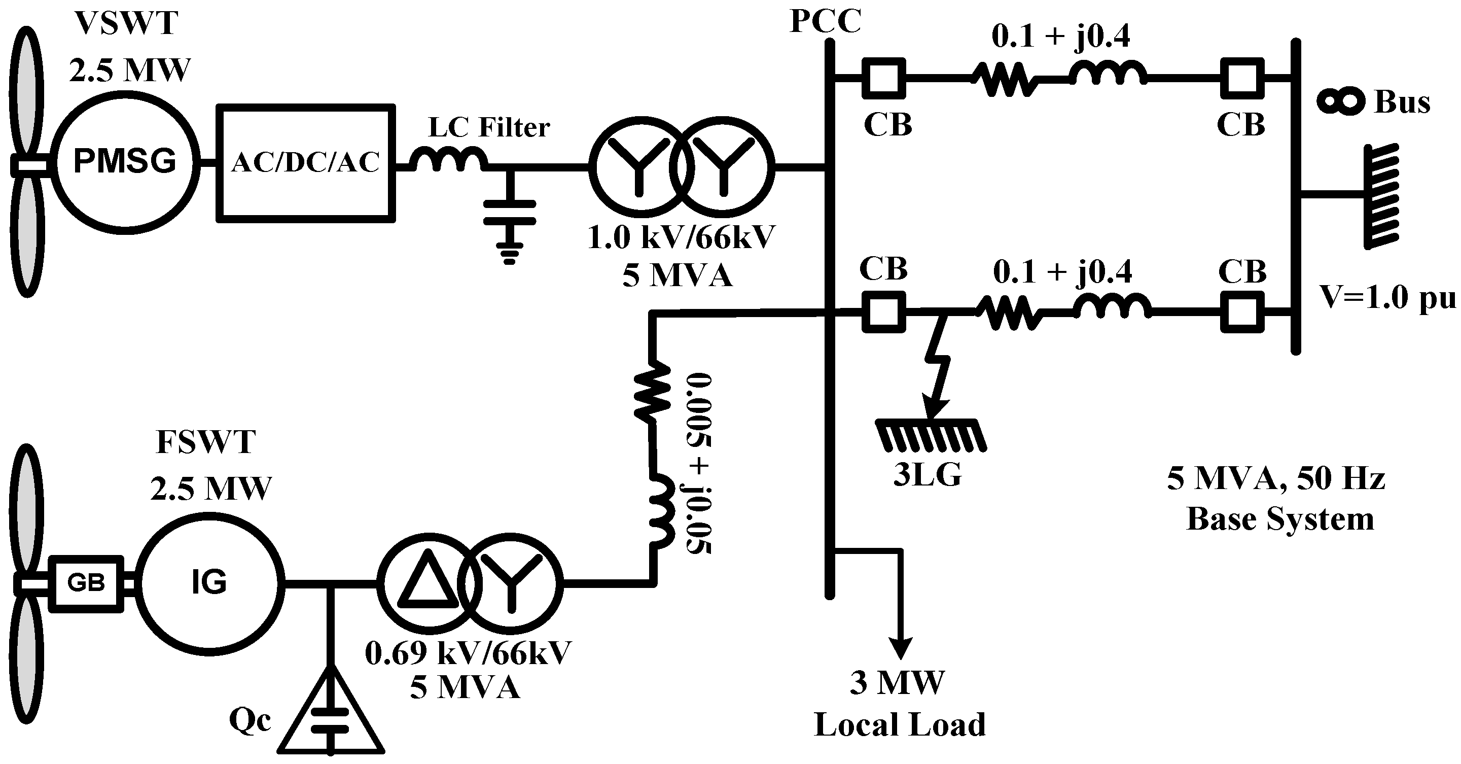
In this paper, a 2.5 MVA class of VSWT-PMSG is considered.
Table 1 presents the system parameters of the grid connected VSWT-PMSG. In order to determine the LC filter parameters, step by step procedures and limitations of the filter parameters presented in [
7] are adopted.
Table 1.
System parameters.
Table 1.
System parameters.
| Component | Parameter | Symbol | Value |
|---|
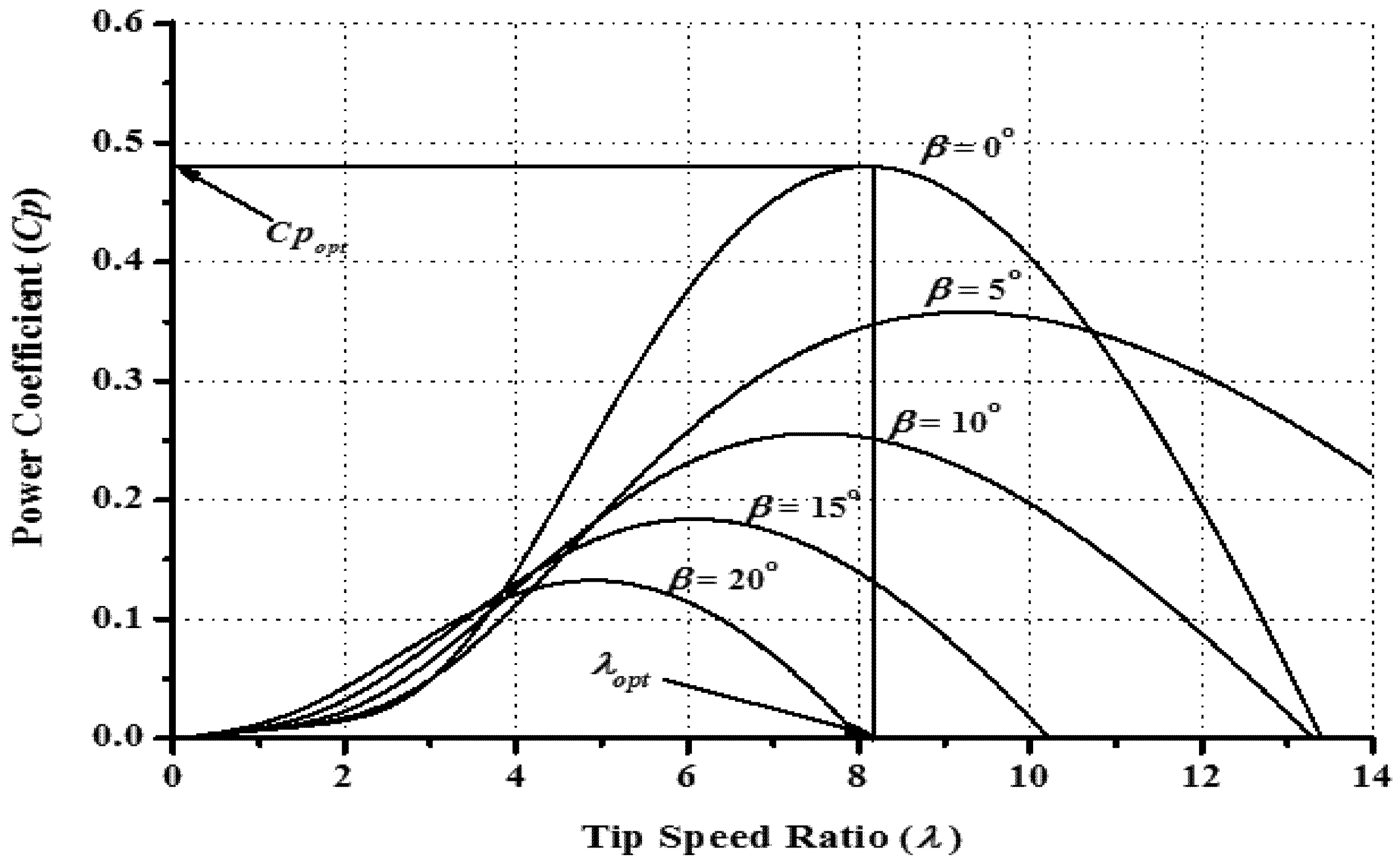
| Wind Turbine | Blade Radius | R | 40 m |
| Rated Wind Speed | Vw | 12 m/s |
| Rated rotation speed | ωr | 2.43 rad/s |
| Maximum Power Coefficient | Cpopt | 0.48 |
| Optimum Tip Speed Ratio | λopt | 8.1 |
| Air density | ρ | 1.225 kg/m3 |
| Inertia | Jwt | 10,137,000 kg·m2 |
| PMSG | Rated Voltage | V | 1.0 kV |
| Rated Frequency | fe | 20 Hz |
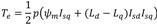
| Magnetic Flux | ψm | 1.4 pu |
| Stator Winding Resistance | Rs | 0.01 pu |
| The d-axis inductance | Ld | 0.95 pu |
| The q-axis inductance | Lq | 0.75 pu |
| Pole pairs | p | 52 |
| AC/DC/AC Power Converter | SSC frequency Switching | fs | 1 kHz |
| GSC frequency Switching | fs | 5 kHz |
| Grid Frequency | fg | 50 Hz |
| DC Link capacitor | Cdc | 25000 μF |
| DC Link voltage | Vdc | 1.75 kV |
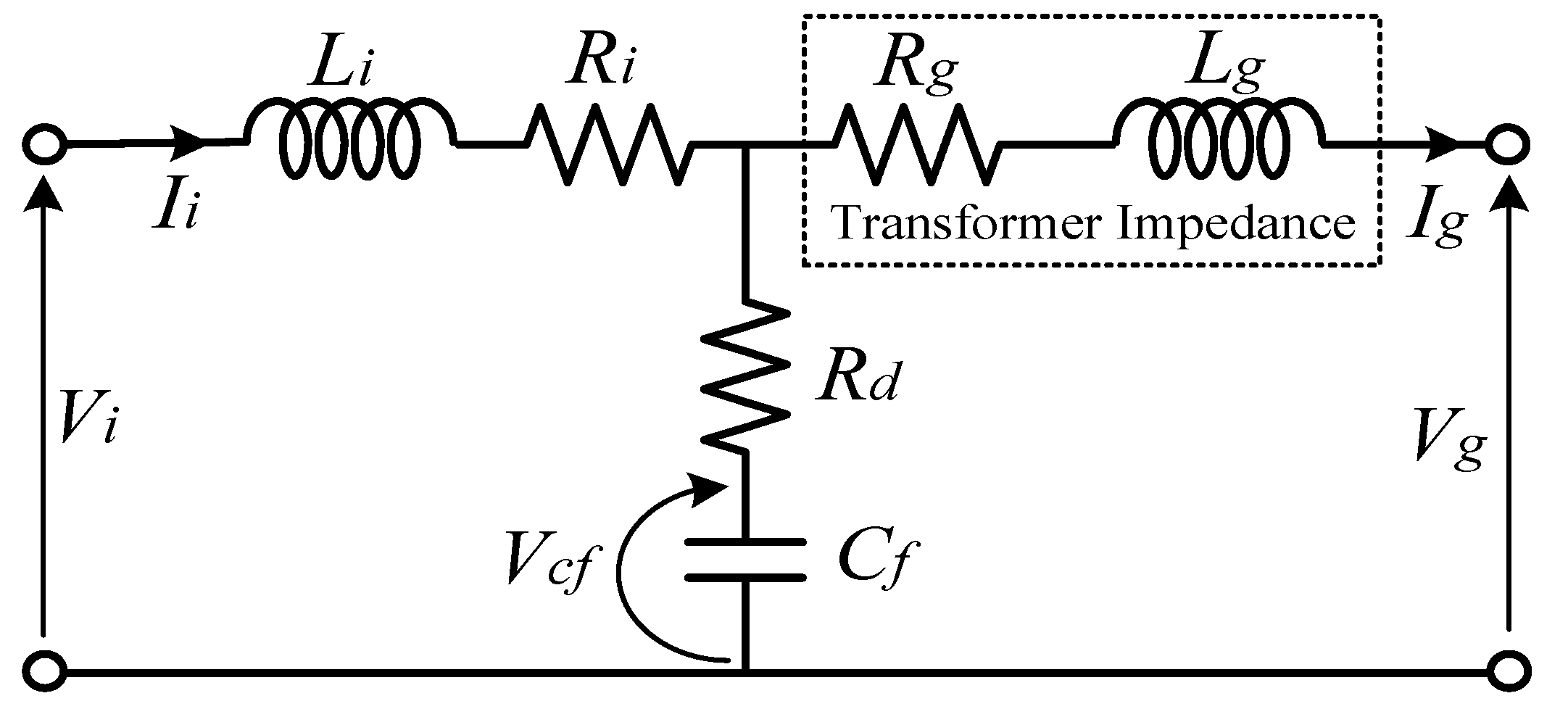
| LC Filter | Inverter side inductance | Li | 0.6 pu |
| Inverter side parasitic resistance | Ri | 0.005 pu |
| Filter capacitor | Cf | 0.05 pu |
| Damping Resistance | Rd | 0.3 pu |
| Step Up Transformer | Transformer inductance | Lg | 0.04 pu |
| Transformer resistance | Rg | 0.016 pu |
| Low voltage | VTL | 1.0 kV |
| High voltage | VTH | 6.6 kV |
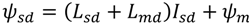
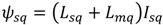
3.1. Stator Side Controller
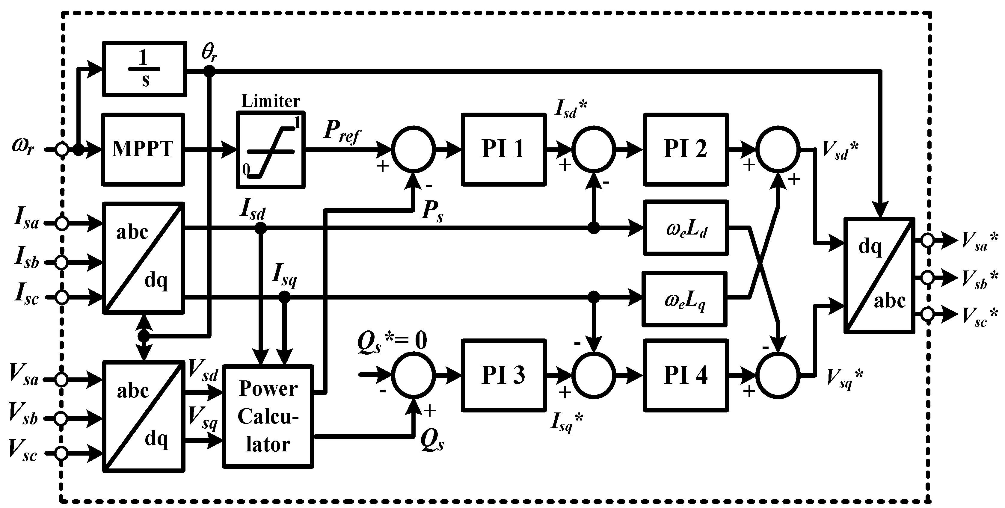
The aim of the stator side controller is to control the active and reactive power output of the PMSG. Details of the stator side controller system are presented in a block diagram shown in
Figure 7. The rotor angle position (
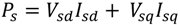
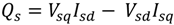
θr) used in the transformation between abc and dq variables is obtained from the rotor speed of generator. The active power (
Ps) and reactive power (
Qs) of the generator are controlled by the d-axis current (
Isd) and the q-axis current (
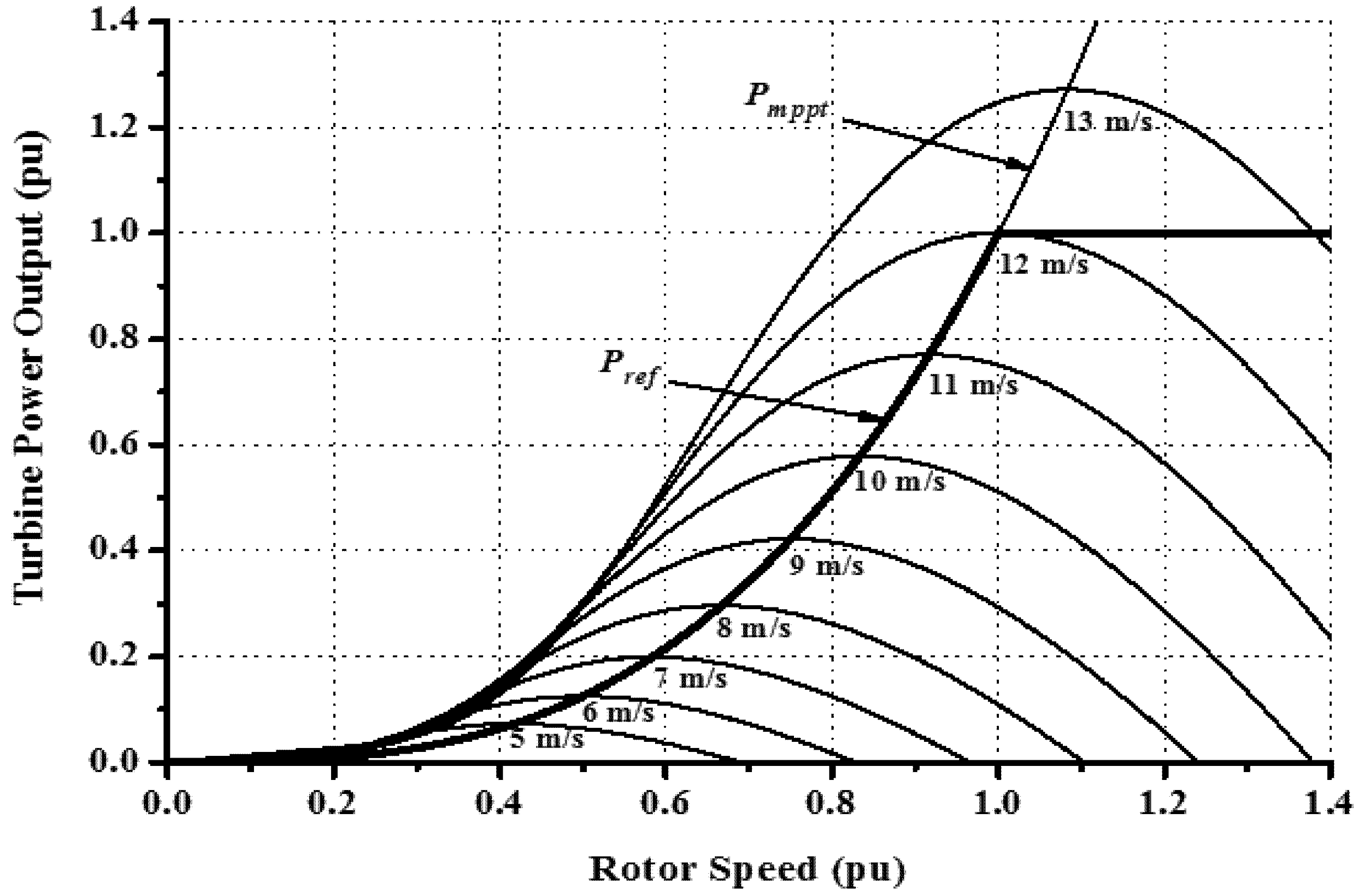
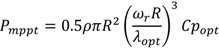
Isq), respectively. The value of active power reference (
Pref) is determined by MPPT method of the wind turbine characteristic as shown in
Figure 2. For unity power factor operation, the reactive power reference (
Qs*) is set to zero. The cross couplings
IsdωeLd and
IsdωeLq should be compensated by the output of the current controllers in order to improve the tracking capability of the control system. Finally,
Vsd* and
Vsq* are voltage reference outputs of the current controller, which is used to generate the three phase reference voltage (
Vsa*,
Vsb*,
Vsc*) to control stator currents of the PMSG.
Figure 7.
Stator side controller system.
Figure 7.
Stator side controller system.
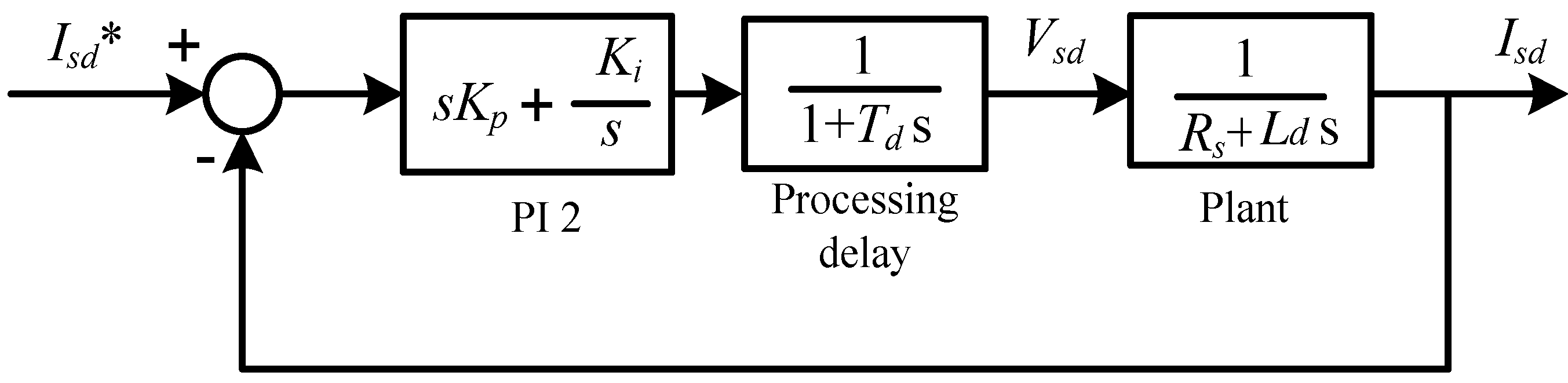
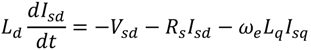
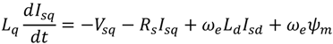
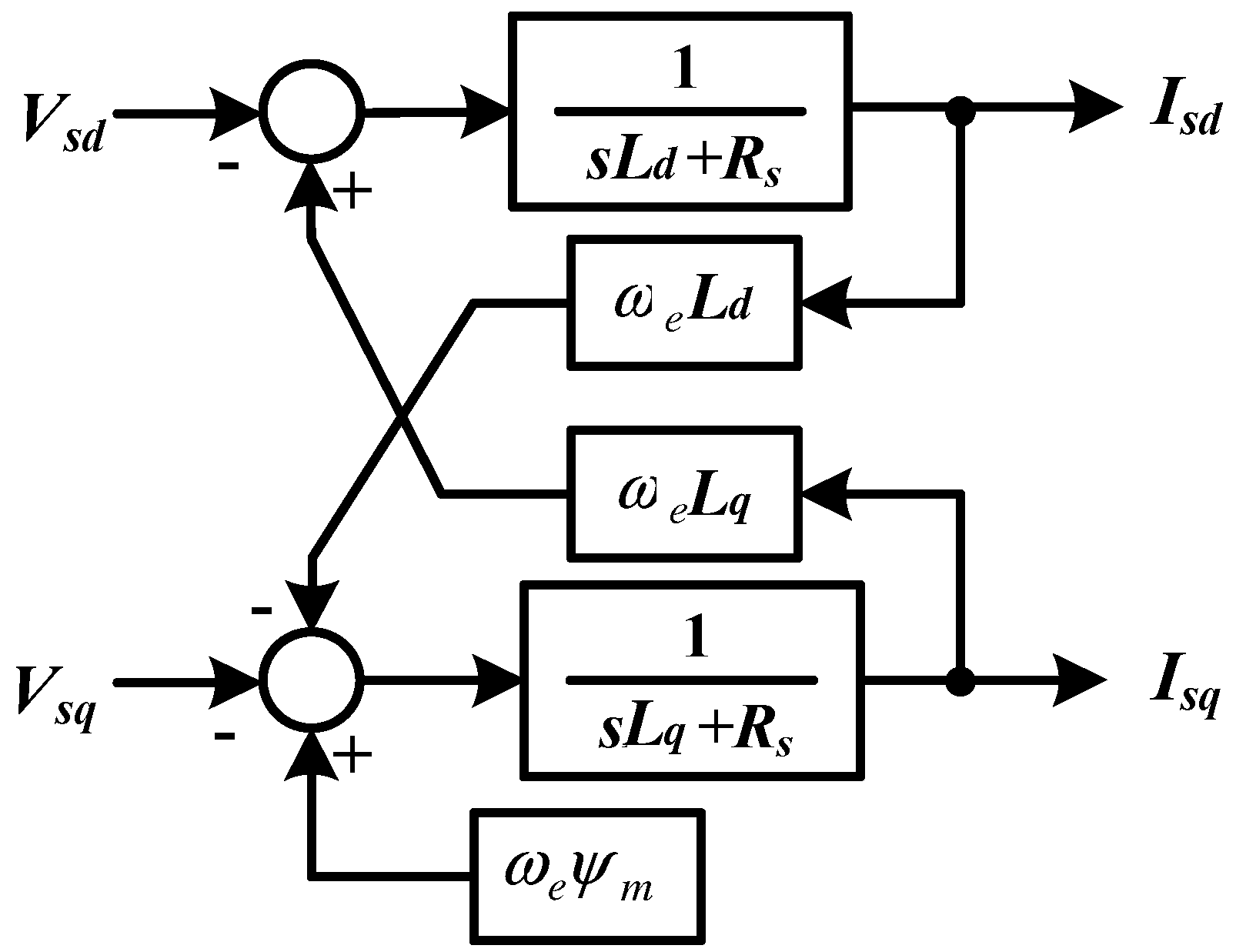
In order to analyze stability performance of the controller system shown in
Figure 7, a block diagram of the current loop control shown in
Figure 8 is used. In this study, the d-axis and the q-axis components are assumed identical, and hence the plant system can be modeled by using one axis component only as expressed by 1/(
Rs +
Lds). The controller is composed of a PI controller (PI 2), a processing delay, and a plant system. The time delay (
Td) is composed of one sample delay caused by switching frequency and one half sample delay caused by the dead time of PWM converter.
Figure 8.
Current control loop of SSC.
Figure 8.
Current control loop of SSC.
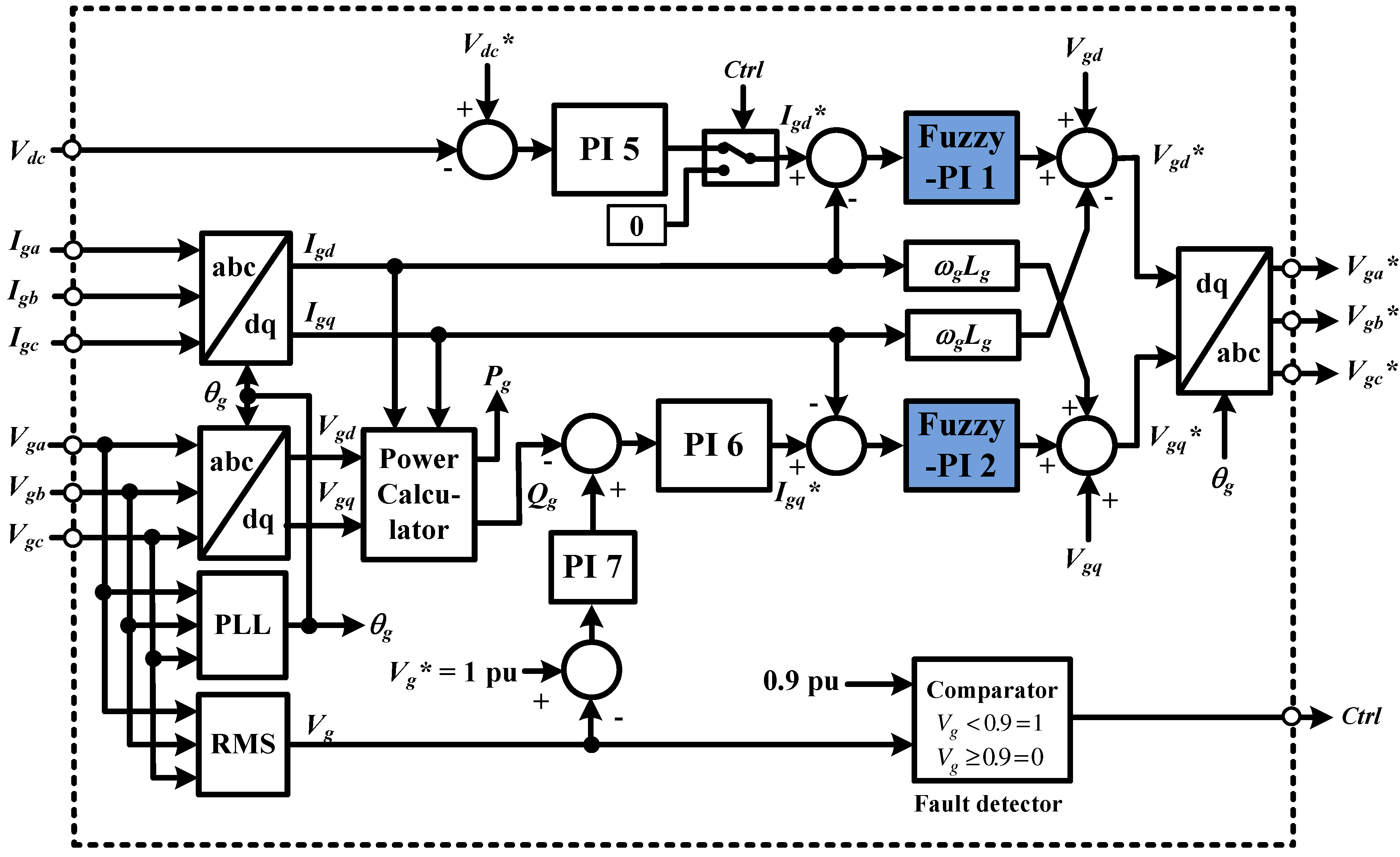
3.2. Grid Side Controller
Figure 9 shows a block diagram of the grid side controller system. In this control strategy, the control system based on the d-q rotating reference frame is implemented, which has the same rotational speed as the grid voltage. The three phase grid currents (
Iga,
Igb,
Igc) and the grid voltages (
Vga,
Vgb,
Vgc) are transformed into the d-q rotating reference frame by using Park transformation. The Phase Locked Loop (PLL) [
15] is used to extract the grid side phase angle (
θg).
Figure 9.
Grid side controller system.
Figure 9.
Grid side controller system.
The controller is divided into two cascade loop control, one for active power and the other is for the reactive power. When grid voltages on the stationary reference frame are transformed into the d-q rotating reference frame,
Vgd is set to constant and
Vgq is set to zero. Therefore, the active and reactive power delivered to the grid can be controlled separately by the d-axis current (
Igd) and the q-axis current (
Igq), respectively. To improve the tracking capability of control system, the cross coupling should be canceled by adding
IgdωLg and
IgqωLg at the output of the current controllers. For d-axis and q-axis current loop regulation, in this paper, the Fuzzy-PI controllers are applied. The control strategy for the Fuzzy-PI controller will be explained in
Section 4. The output of current controller (
Vgd* and
Vgq*) is transformed into the stationery reference frame (
Vga*,
Vgb*,
Vgc*), which is used as a reference signal for pulse wave modulation.
Under normal operating conditions, the voltage of DC-link capacitor (Vdc) is maintained constant in order to transfer the active power generated by PMSG to the grid. The d-axis current reference signal (Igd*) is determined from the output of the DC-voltage controller, and the q-axis current reference signal (Igq*) is obtained from reactive power controller output. The reactive power reference (Qg*) is set so that the terminal voltage at the high voltage side of the transformer remains constant.
In grid fault condition, the fault detector is activated when the grid voltage decreases under 0.9 pu. The detector sends the control signal command (Ctrl) to trigger the DC link protection. At the same time, the active power transfer to the grid is set to zero.
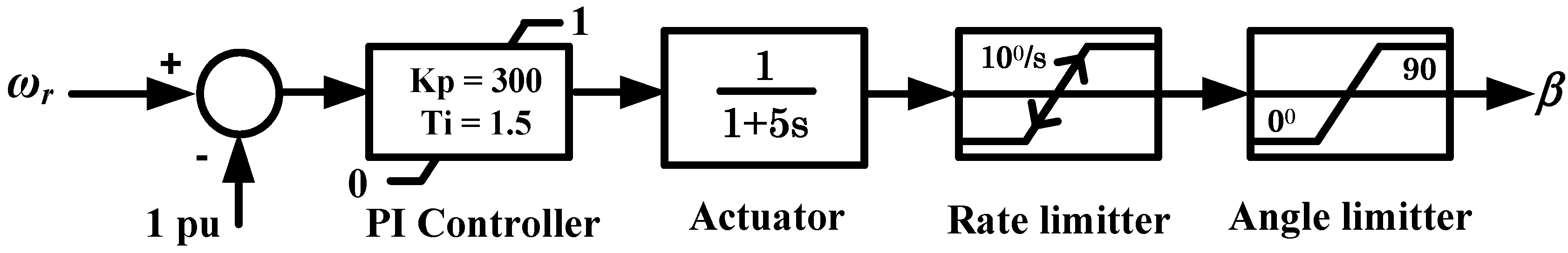
3.3. Pitch Controller
Figure 10 shows the model of the pitch controller for VSWT. The control loop of the pitch actuator is represented by a first-order transfer function with an actuator time constant (
Ts = 5) and the pitch rate limiter of 10°/s. A classical PI controller is used to manage tracking error. In VSWT the pitch controller is used to regulate rotational speed of PMSG under its rated value (1 pu).
Figure 10.
Pitch controller.
Figure 10.
Pitch controller.
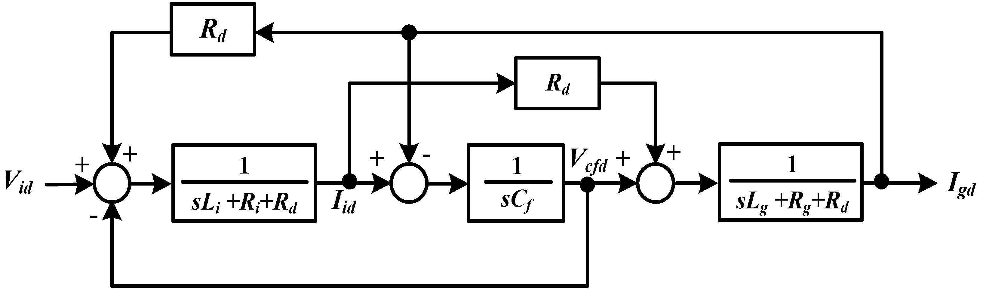
4. Fuzzy-PI Controller Design
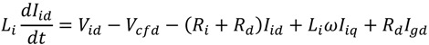
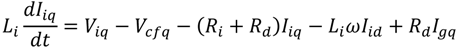
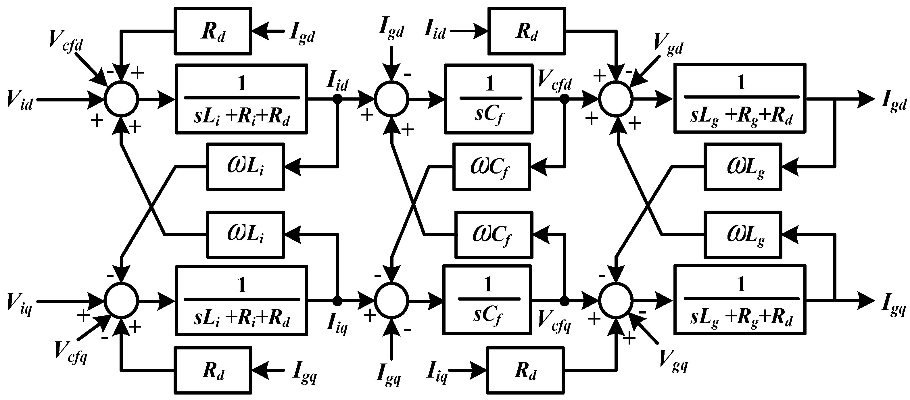
In order to design a fuzzy logic controller (FLC) for the current control loop, the block diagram of LC filter in the d-q rotating reference frame shown in
Figure 6 is considered as a plant system. The plant system can be modelled by using the d-axis component only as shown in
Figure 11, where the cross coupling and the grid voltage are neglected.
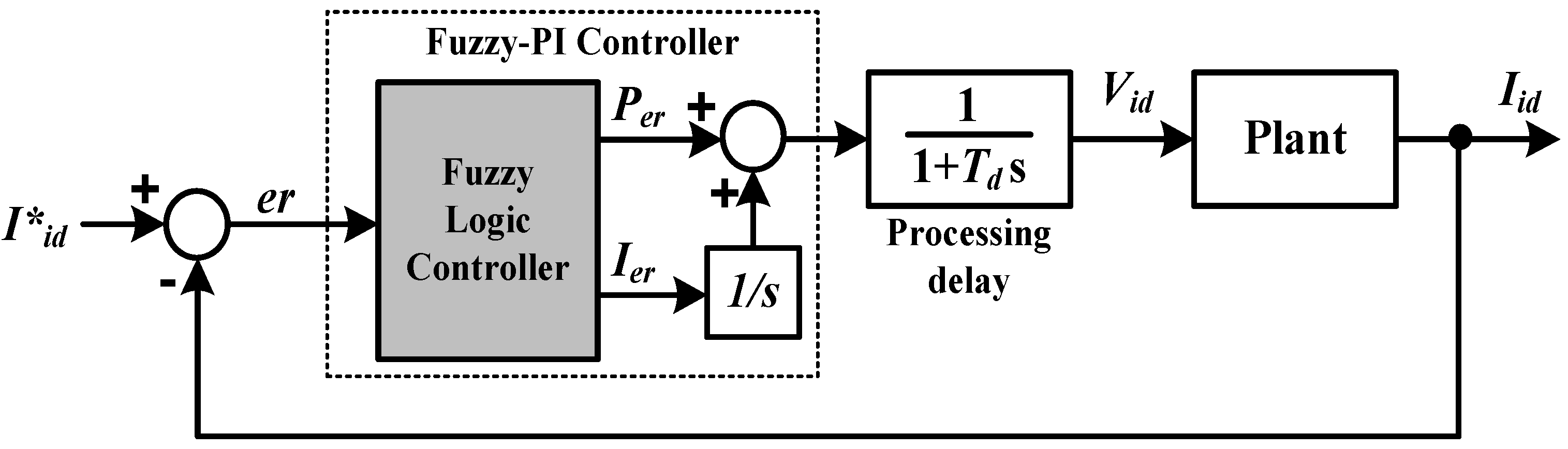
Figure 12 shows a block diagram of the current control loop for GSC. The control system is composed of a Fuzzy-PI controller, a processing delay, and a plant system, using the converter side voltage (
Vid) as input and the converter side current (
Iid) as output. The FLC is used to adjust the PI parameters according to the input signal error (
er). To determine a control signal for proportional signal control (
Per) and integral signal control (
Ier), an inference engine with rule base having if-then rules in form of “If
er, then
Per and
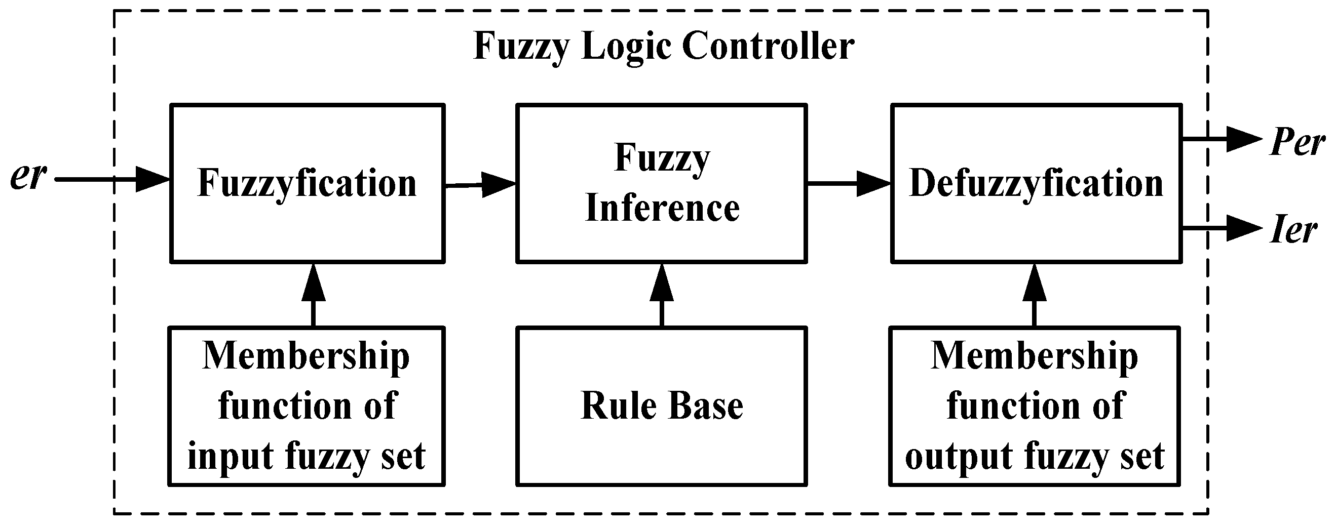
Ier” is used. The general structure of the fuzzy logic control is shown in
Figure 13. The FLC is composed of fuzzification, membership function, rule base, fuzzy inference and defuzzification.
Figure 11.
The LC filter in d-axis component only.
Figure 11.
The LC filter in d-axis component only.
Figure 12.
Current control loop of the grid side converter (GSC).
Figure 12.
Current control loop of the grid side converter (GSC).
Figure 13.
Block diagram of fuzzy logic controller.
Figure 13.
Block diagram of fuzzy logic controller.
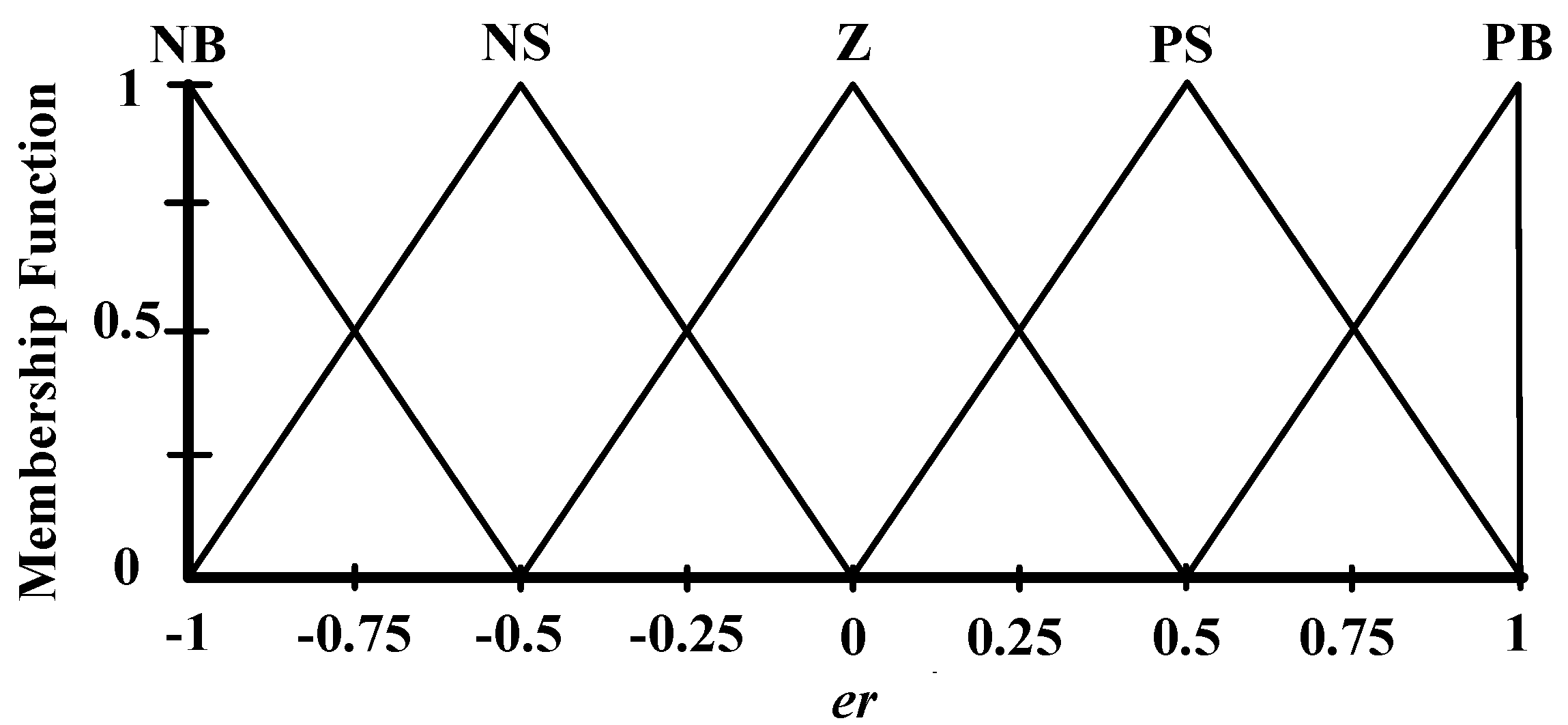
The fuzzification comprises the process of transforming crisp values into grades of membership for linguistic terms of fuzzy sets. The membership function is used to associate a grade to each linguistic term. For fuzzification, the three variables of the FLC—the error (
er) and the outputs of
Per and
Ier—have five triangle membership functions. The variables fuzzy subsets for input are Negative Big (NB), Negative Small (NS), Zero (Z), Positive Small (PS), and Positive Big (PB).
Figure 14 shows the membership function for input
er. The interval input of the membership function is set at [−1 to 1] due to the variation of the d-axis or q-axis current between −1 to 1 pu.
Figure 14.
The membership function for input er.
Figure 14.
The membership function for input er.
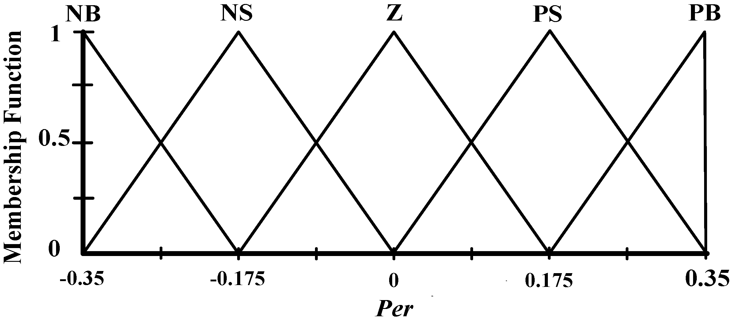
Figure 15 and
Figure 16 show the membership functions of output for
Per and
Ier, respectively. The membership functions are designed based on frequency response of the bode diagram of the current control loop. In this paper the initial gain
Kp is obtained by using optimum modulus criterion. The integral time constant (
Ti) usually set equal to the plant system time constant (
Ltot/
Rtot) [
6], where
Ltot and
Rtot are total of series inductances and its parasitic resistances of the plant system, respectively. The integral gain can be calculated by using
Ki =
Kp/
Ti.
Figure 15.
The membership function for output Per.
Figure 15.
The membership function for output Per.
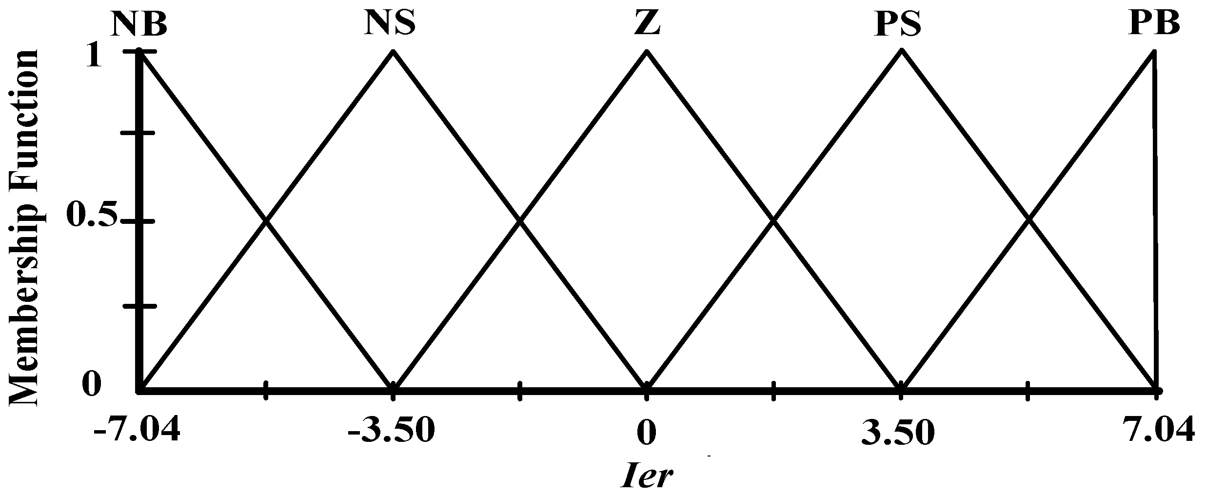
Figure 16.
The membership function for output Ier.
Figure 16.
The membership function for output Ier.
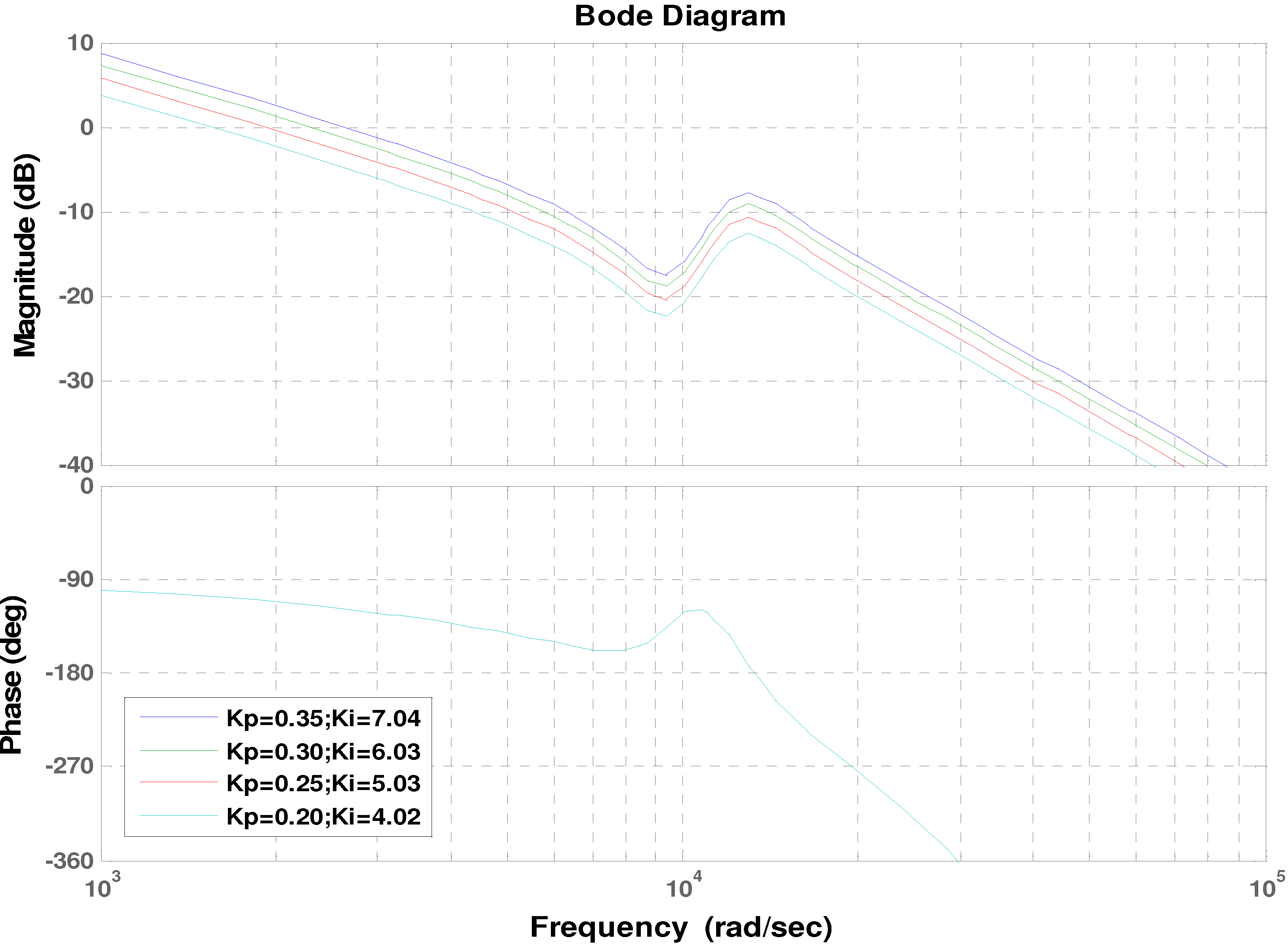
Figure 17.
Bode diagram of current control loop of GSC.
Figure 17.
Bode diagram of current control loop of GSC.
Figure 17 shows frequency response of the bode diagram of the current loop control of GSC for four different values of
Kp and
Ki. It is seen that maximum gain with gain margin (Gm) larger than 10 dB and phase margin (Pm) larger than 45° is obtained with
Kp = 0.35 and
Ki =7.07. Therefore, the interval of membership function for output
Per and
Ier can be set at [−0.35 to 0.35] and [−7.04 to 7.04] as shown in
Figure 15 and
Figure 16, respectively.
The rules are set based upon the knowledge and working of the system. The values of Per and Ier for Fuzzy-PI controller of the current regulator are calculated for the changes in the input of the FLC according to the rule base. The number of rules can be set as desired. A rule in the rule base can be expressed in the form:
If (er is NB), then (Per is NB) and (Ier is NB)
If (er is NS), then (Per is NS) and (Ier is NS)
If (er is ZE), then (Per is ZE) and (Ier is ZE)
If (er is PS), then (Per is PS) and (Ier is PS)
If (er is PB), then (Per is PB) and (Ier is PB)
The rule base includes five rules, which are based upon the five membership functions of the input variables to achieve the desired Per and Ier.
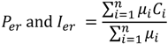
In this work, Mamdani’s max-min method is used for inference mechanism. The centre of gravity method is used for defuzzification to obtain
Per and
Ier, which is given by the following equation:
where,
n is the total number of rules,
μi is the membership grade for the i-th rule, and
Ci is the coordinate corresponding to respective output or consequent membership function.
To analyse the dynamic performance of current control loop, the linear block model as shown in
Figure 11 is used. The analysis has been performed by using Matlab/Simulink.
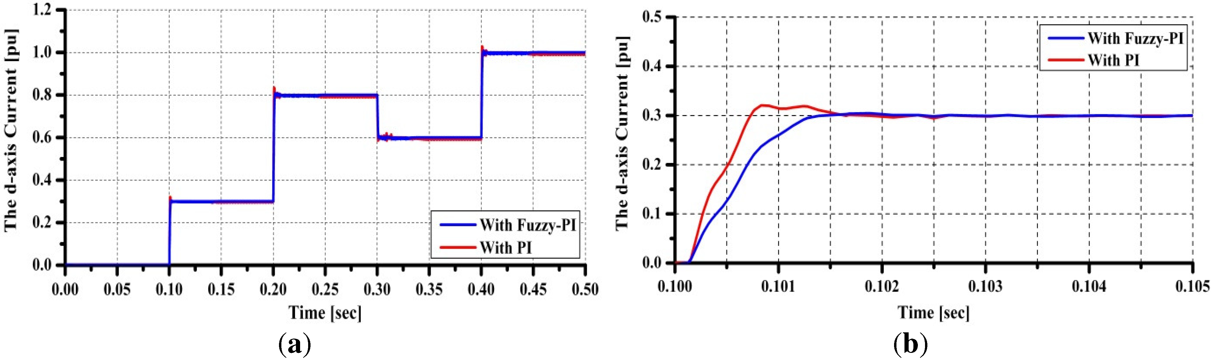
Figure 18 shows step response of the current control loop. The reference for the
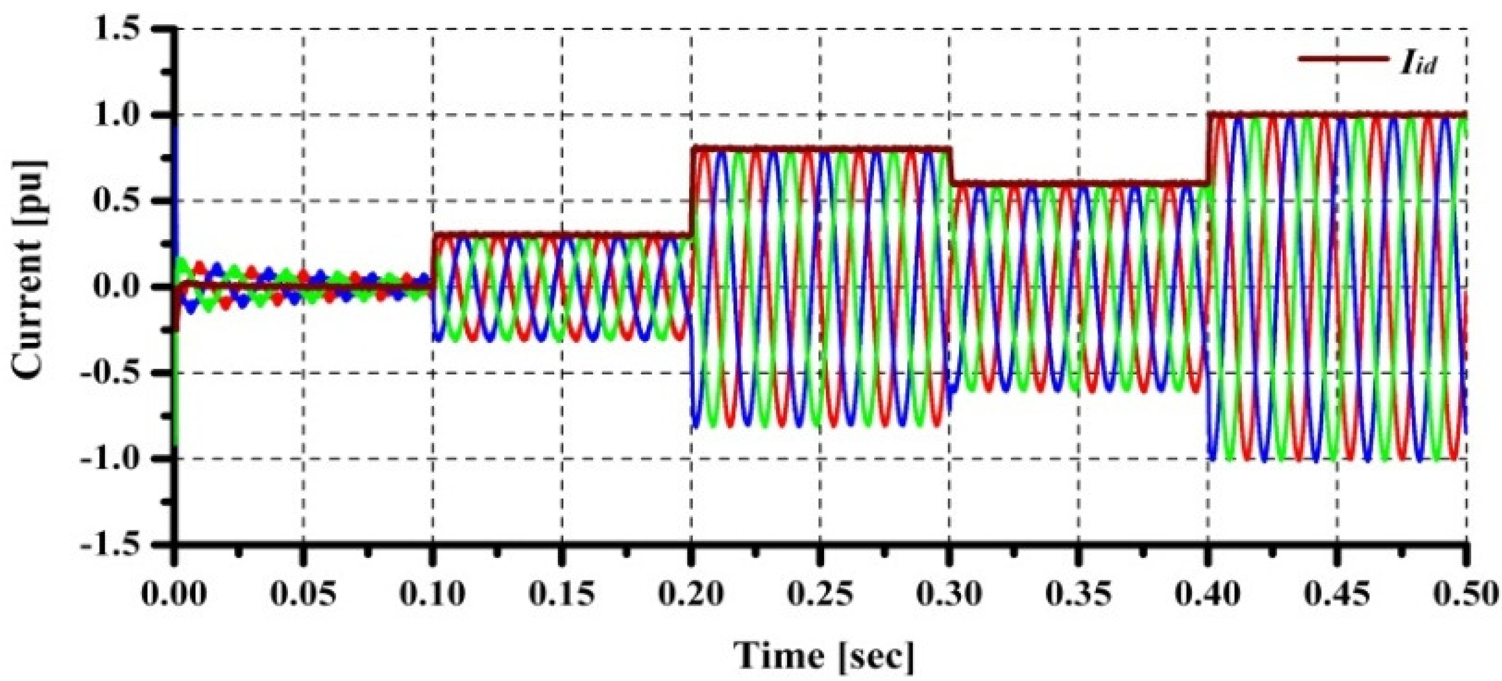
d-axis current has been varied four times at every 100 ms. It is seen that good performance can be achieved by using proposed Fuzzy-PI controller. The three-phase current on the grid side, as well as
Iid, have been observed by using power system blockset as shown in
Figure 19. It can be seen that the three phase current tracks the reference very well.
Figure 18.
Linear block model analysis.(a) Step response; (b) Zoom of step response at 0.1 s.
Figure 18.
Linear block model analysis.(a) Step response; (b) Zoom of step response at 0.1 s.
Figure 19.
Power system blockset model analysis.
Figure 19.
Power system blockset model analysis.


