Article

An Evaluation of the Tool Wear of Ceramic and Coated Carbide Inserts in Finishing Turning under the Influence of Age-Strengthening Gray Cast Iron

by
N. E. González-Sierra
1,
Javier Flores Méndez
1,2,
M. A. Meraz-Melo
2,
Ana C. Piñón Reyes
2,
German Ardul Munoz-Hernandez
1,
Alfredo Morales-Sánchez
3,
Mario Moreno Moreno
3 and
Gustavo M. Minquiz
1,2,*
1
Área de Ingeniería, Benemérita Universidad Autónoma de Puebla, Ciudad Universitaria, Blvd. Valsequillo y Esquina Av. San Claudio s/n, Col. San Manuel, Puebla C.P. 72570, México
2
Ingeniería Mecánica, Tecnológico Nacional de México/I.T. Puebla, Av. Tecnológico #420 Col. Maravillas, Puebla C.P. 72220, México
3
Departamento de Electrónica, Instituto Nacional de Astrofísica, Óptica y Electrónica, Luis Enrique Erro No.1, Sta. Ma. Tonantzintla, Puebla C.P. 72840, México
*
Author to whom correspondence should be addressed.
Appl. Sci. 2023, 13(18), 10248; https://doi.org/10.3390/app131810248
Submission received: 2 August 2023 / Revised: 5 September 2023 / Accepted: 8 September 2023 / Published: 13 September 2023
(This article belongs to the Special Issue Advanced Manufacturing Processes)

Abstract

:
Gray cast iron (GCI) is a common material in the automotive industry due to its mechanical characteristics, which change primarily for materials employed for the foundry and cooling rate of material. According to the workpiece, the material of the cutting tool and cutting parameters are analyzed to improve the machining and to increment the lifetime of the tools. In this research, the foundry and machining process of an automotive component using ceramic and coated carbide tools were the study case, and the effect that they have on the age strengthening of GCI on the tool wear of the cutting tools was studied. Both inserts have the capability to machine the material with a rough surface between 1.5 to 2.0 μm. The wear mechanism of inserts and the microstructure of GCI were characterized with microscopy techniques, atomic force microscope (AFM), and energy dispersive X-ray spectroscopy (EDS). The microstructure of the workpiece shows a casting with flake graphite morphology that is linked with the induction of microcracks in the material. The experimental analysis shows that the GCI with 12 days of aging has an increased tensile strength. This improves the tool life of ceramic and coated carbide tools. There is a 50% reduction in flank wear with inserts that are machined with the GCI within five days of aging, compared with the material within twelve days. The rake face and flank wear show that abrasive and adhesive wear are the main mechanisms of ceramic inserts due to the high cutting speed. Meanwhile, adhesive and oxidative wear in the flank were the predominant type of wear for coated carbide tools.

1. Introduction

The foundry irons can be summarized in the following steps: (a) Metal melting: First, the melting process of various metallic materials and alloys is carried out to obtain gray iron. (b) Mold making: The disk mold is made by a process known as High-Density Vertical Molding. (c) Casting: This process consists of filling the mold cavity with molten liquid metal. After cooling, the metal solidifies and the sand is removed from the mold. At last, the cast material is transported to the machine shop [1]. Cast irons have a low melting point compared to steel, and these are carbon-rich iron-base alloys arranged near cementite or eutectic graphite. The GCI is usually machined in the as-cast condition, but the solidification process plays an important role. There are two variables that determine if the matrix could be austenite, ferrite, or a mixture of ferrite and perlite; those are the cooling rate and alloy composition [2]. Compacted Graphite Iron (CGI) presents a challenge in terms of machinability. An alternative to optimize the manufacturing process is the use of a metalworking fluid diluted between 4% and 9% and containing a 0.3 sulfur compound, with cutting lengths of 6.0 and 4.8 km [3]. The mechanical and microstructure performance of the GCI in a pearlitic state can be altered by the point of extraction foundry, even with the same composition. Additionally, the graphite content is determinant in mechanical behavior, and the fine structure of eutectic cells increases the fatigue limit as the phosphorous improves the tensile strength [4]. The hardness properties of the grey cast iron are determined by the cooling rate, which are related with the primary dendrite arm spacing (DAS), the secondary dendrite arm spacing (SDAS), and the thickness of the ferrite–cementite layer (le). While the cooling rate increases, the eutectoid thickness decreases. Eutectic cells are combined with interconnected graphite plates that surround austenite in the ferrite–cementite layers. An effect of the undercooling is the degree of ramification of graphite and the spacing [5]. The solid transformation of the GCI consists of releasing heat; this change of phase is divided into two points of interest that are described through a curve of the temperature as a function of the time. The first point occurs between 1140 to 1150 °C and 40 to 50 s; the collected data are related to the shrinkage behavior of the iron. The undercooling at the second point and graphite growth beyond are determined by the onset of the eutectic solidification of graphite and austenite. The mentioned phase occurs between 1130 to 1140 °C and 50 to 100 s [6]. The gray cast iron properties and microstructure were analyzed in a foundry process under different cooling methods. The study tested four approaches: as-cast, furnace-cooled, air-cooled, and green sand-cooled. The results showed the variation of cementite Fe3C with 24.96, 11.64, 6.62, and 6.35 percent respectively, and the consequence is the differences in the hardness Rockwell scale of 95.8, 85.2, 94.7, and 97.0 HRB [7]. As the foundry process progresses, the crystal structure begins to re-form on cooling at the melting point, especially in solidifying when energy is given out in the form of the latent heat of fusion. Solidification depends on the rate at which heat can be removed. While the solidification is in a slow rate, the first nuclei increase in size as more eventually has transformed into large grains. Initially, the grain boundaries represented the points of growth outward from the nuclei. The number of clusters increases when cooling is rapid, and each cluster grows rapidly as a result. As more grains are formed in the solid, the metal is finer [8]. A constant temperature gradient is shown in Figure 1, which represents the solidification temperature increase as a function of the solidification rate for the Fe-4.28C eutectic composition. Possible solid constituents include g/graphite eutectic, g/cementite eutectic, and g/austenite dendrites. The dotted line indicates the phase with the highest interface growth temperature. The g/Graphite eutectic forms with a low solidification rate, followed by austenite dendrites, whereas the g/cementite eutectic forms with a high solidification rate [2].
Age strengthening is the final phase of the foundry process in gray cast iron, where the mechanical properties are defined. Tool wear and vibration are the principal issues during the machining process; the common solution had been stocking parts for a few days to reach metallurgical stability. A brake disk of gray cast iron was analyzed for hardness during aging, and the data collected showed that the metallurgical stability was reached at seven days. The investigations exhibited the importance of industrial conditions before machining the casting [9,10]. An investigation has been conducted into the influence of age on the machining of a component of an automobile with a polycrystalline cubic boron nitride (PCBN) cutting tool. The test indicated that the tendency to improve the tool life is not under control during the first 100 h. After this time, there is a stable trend [11]. The age-strengthening effect in gray cast iron was analyzed, in terms of ultimate tensile strength, and the data collected showed a variation between 3.3% and 13% [12]. The age strengthening appears as nitride precipitation in ferrite. It appears that elements that interact with N, such as Mn, disturb the strength of the aging process, and the gray cast iron’s machinability improves along with age-strengthening, particularly with free ferrite present [13]. Some foundry companies have established that five-day to room temperature aging provides a good balance between production and shipping and can require floor space [14].
A review of the literature found that the nature and temporal behavior of age strengthening are supported in two relevant aspects [13]. First, during the melting process, free nitrogen into iron-based alloys is required for the aging effect. Because this influence of the nitrogen could be related with the precipitate and diffusivity in the microstructure, which is validated to the fact that nitrogen is better diffused when the casting is cooling at room temperature [15]. In addition, the weight percent of iron–nitride (Fe4N) is linearly correlated with the changes of the ultimate tensile strength (UTS) from age strengthening, which implies that Fe4N significantly promotes the precipitate [16]. Second, the tests realized the effects of the aging temperature, which have demonstrated that it is possible to increase the rate of age strengthening when immediately after the casting, a temperature of 182 °C or 285 °C is applied to the GCI. For the last case (285 °C), the aging is accelerated through reaching a peak in tensile strength in approximately five hours [9,17]. However, after five hours, if the process of heating continues, over-aging occurs that decreases the tensile strength [18]. In contrast, the same effects can take any amount of days or a few weeks for the aging of GCI at room temperature. In this work, the workpiece was cooled at room temperature, and accordingly, the aging was a slow process. Additionally, it can be deduced that the influence of nitrogen exists in casting because the aging workpiece improves the machining.
Based on previous research, casting material properties are defined considering the cooling rate or the influence of the content metals in the foundry process. Even more, age strengthening of the cast iron defines the casting mechanical properties. The present study aims to evaluate the tool wear mechanisms after five and twelve days from casting. As a case study, finishing turning operations with automotive material were tested using two cutting tool materials. A tool wear microscopy analysis was performed to examine the difference between ceramic and coated carbide inserts. This comparative considers the variation in age strengthening that occurs with the GCI.

2. Review of Wear Mechanism in a Grey Cast Iron Machining Process

Different cutting tools have been used in the machining of gray cast iron. The material from which the tool is made is a fundamental characteristic because it shows the effects of the interactions between the cutting tool and the workpiece [19]. Tool life optimization is a concerning discussion in a machining process, the change of cutting parameters affects the performance of others, and there is a complex relationship. Consequently, the cutting tool characteristics must have superior toughness, hot hardness, thermal shock resistance, oxidation resistance, and affinity with the material to be machined [20]. It is possible to machine with ceramics and PCBN tools with good productivity or quality surface, and the cutting speed parameter can be between 500 and 2000 m/min [21]. The machinability of the PCBN chamfered tool in the dry turning of gray cast iron has been investigated. To evaluate the tool wear mechanism, the cutting parameters were fixed as VC = 204 m/min, aP = 0.4 mm, and fn = 0.2 mm/r for the cutting speed, the depth of cut, and the feed rate, respectively. The main wear mechanisms found were material adhesion and microchipping due to the negative rake angle on the tool chamfer. The embedded material on the flank face suffered severe friction during the cutting process, causing some of the tool material to drop off, and this will chip, forming micro notches. An energy dispersive X-ray spectroscopy (EDX) analysis of the adhered material on the tool confirmed the presence of elements such as Fe, Si, and Mn, which correspond to the composition of gray cast iron [22]. The cutting properties of boron nitride dispersed cemented carbide (BNDCC) inserts that are a hybrid between cemented carbides, and cubic boron nitride (CBN) cutting tools have been analyzed. The tool wear was evaluated during grooving spheroidal cast iron by varying cutting speeds, such as VC ≤ 317 m/min for coated and VC ≤ 176 m/min for uncoated BNDCCs. The results show that adhesion wear predominates in the different types of BNDCC inserts. The build-up edge (BUE) is significantly major in uncoated BNDCC inserts, which is attributed mainly to the high friction in the tool flank-workpiece interface. In comparison, the BUE formation for coated (with TiN and TiAlN) BNDCC inserts is associated with the characteristics of the coating, which increases the coefficient of friction between the chip and gray iron cast [23,24]. The PCBN cutting tools have been used for the high-speed machining of EN-GJL-250 gray cast iron because they increment the tool life and material removal rate. A paper showed the tool wear mechanisms with PCBN of different compositions and geometry. The cutting data of the tests are: VC = 1300 m/min, fn = 0.5 mm/r, and aP = 0.7 mm. Under these conditions, the results of scanning electron microscope (SEM) observations showed an adhesion layer strongly attached in the tools, which were cleaned by etching in an ultrasonic bath to be certain of the measure of the flank wear. This built-up layer can act as a medium of tool protection during turning [25]. A cemented carbide insert WC–5TiC–0.5VC-8Co (WTVC8) was tested on a machining gray cast iron (HT250). In this case, the wear morphology and EDS analysis conclude that adhesive wear was the principal wear mechanism on the flake face in the cutting tool [26]. A carbide tool SNMA 12408 chemical vapor deposition (CVD), coated with titanium carbonitride, aluminum oxide, and titanium nitride, was tested on machining gray cast iron. For understanding the sulfur influence, the cutting parameters configured were VC = 100, 150, and 200 m/min, fn = 0.257 mm/r, and aP = 2 mm. The wear mechanisms were the adhesion and chips on the tool face with casting machining with a 0.065% sulfur content; furthermore, the tool life was reduced to 24, 32, and 38%, respectively, with each cutting speed tested [27]. For machining CGI, SNMA 120408 KR 3205 and 3210 inserts were tested. The cutting tools have a multilayer coated carbide of Ti(CN) and Al2O3 as exterior coating and an additional thin TiN coating. The parameters set were Vc = 250 m/min, fn = 0.2 mm/rev, and aP = 2 mm, and the results of the configuration were a few chippings and a more extensive flank and crater wear [28]. The relation between the flank-wear decreasing when cutting speed is above 900 m/min was studied, and the behavior was explained with a CBN cutting tool. The degradation happens because the oxidized Fe reacts with CBN and from B2O3 [29]. The insert NP-TNGA 160412GS3 MB710 with a cover layer of TiC and Al2O3 is an alternative, analyzed in the GCI machining. This tool was experimented with in orthogonal arrays, and the parameters are VC = 750 to 1050 m/min, fn = 0.05 to 0.15 mm/rev, and aP = 0.1 to 0.2 mm. The combined analysis of thermal, SEM, and EDX has shown that tool life increases when the cutting speed does not exceed 850 m/min when using CBN inserts. This is explained by the phase transformation of the workpiece material from the pearlite to the austenite phase. In addition, chemical degradation and tool life decreased when the insert reached 1000 °C [30]. Based on previous research, grey cast iron has been machined with ceramic or coated carbide tools with a good surface finish.

3. Procedures for Experiments

The material used in this research is a cast iron metal workpiece that will eventually become a brake disk. The sequence followed by the industry process to produce the brake disk is shown in Figure 2a. Two options are available: 5 or 12 days of age-strengthening casting. The machinery worker decides between ceramic and tungsten carbide tools. Due to the benefits of the reduced cycle time, the manufacturer selected cutting parameters according to the recommendations of the toolmaker while maintaining a maximum cutting speed and feed per tooth. The brake manufacturer utilized a CNC (Puma V400, Doosan, Seoul, South Korea). The spindle rotates at 3000 rpm, and the maximum feed speed is 2000 m/min. Figure 2b summarizes the experimental process carried out in this work. The first step is to analyze the workpiece using an optical microscope and EDS mapping to study its morphology and the distribution of its elements. Second, the cutting tool was characterized with microscopy techniques for identifying the type of wear and the flank wear. Additionally, the adhered material on the inserts was inspected using a scanning electron microscope (SEM) and an energy dispersive X-ray spectrometer (EDX). To identify the damage zone in the inserts, a microscope (B-Serie, Optika, Ponteranica, Italy) was used to measure the flank wear at a 10 X fair value to the 100 X real size. Cutting tool samples were placed on a base with their flanks facing the instrument lamp, and the corner radius was measured starting from the edge to the damage inside. The details on the flank wear and rake face were analyzed using a SEM (SU3500, Hitachi, Tokio, Japan) with 10 kV and a magnification of 39.5 × 170 mm. The flank wear was measured and compared according to the specifications of ISO 3685 [31], which describes that the tool life admissible is 0.3 mm in carbide and ceramic indexable tools. Surface roughness was acquired through the measurement with the atomic force microscope AFM (EasyScan, Nanosurf, Liestal, Switzerland). The instrument is set up on a non-contact mode, and the probe model is configured with a tapping mode AFM probe and a long cantilever. Then, an oscillating AFM probe senses long-distance van der Waals forces. The EasyScand DFM version 2.3 software generates the images.

Brake Machining Process Details from the Manufacturer

Table 1 shows that the CNMG is an insert of a carbide substrate with chemical-coated CVD. This coating consists of a hard top layer combined with Al2O3 and carbon-rich TiCN base layers as the main features of this tool [32]. The SCGN insert (Ceramic,CeramTec,Plochingen, Germany) is based on standard silicon nitride ceramics grades SL 500 [33].
An automotive brake disk is the study case, and the working surface of the disk is the study section. Figure 3a shows the shape and diameter of the workpiece, and the cut line sections indicate the solid material in the brake. Figure 3b indicates with the arrow to the remotion material area, which has an area of 10,162.4 mm2, considering that the parameter of the depth of the cut is 1 mm because it is finishing turning.
The choice of cutting tool type includes the shape and geometry of the cutting edge, which affects vibration and tool life. Additionally, it is considered the insert material or the combination of materials that constitute the cutter’s tool edge. Then, the supplier proposes the cutting parameters in a range of values for cutting speed, depth, and feed per tooth of the insert according to its characteristics. The data is where the insert has the best compromise to remove the material, and it is necessary to calculate the spindle speed and feed rate, which determine the cycle time and quality of the surface [20,34]. Due to the aging of the GCI conditions, the brake manufacturer applied a practical solution to reduce chatter and maintain a rough surface between 1.5 and 2.0 μm, resulting in the use of two inserts, SCGN and CNMG, even though the inserts are made of different materials. According to the tool manufacturer, the SCGN insert works with cutting speeds up to 1200 m/min. In the ceramic cutting tool, the brake maker chose a parameter of 1115 m/min, which is a high value (Table 2). For both cutting tools, the constant parameter was the depth of cut at 0.1 mm. On the other hand, the coated carbide insert CNMG was configured with 650 rpm and 724 m/min, while the tool suppliers recommended cutting conditions between 150 to 700 m/min. The insert machined 40 workpieces with a cycle time of 0.18 s. The two inserts were configured in one pass because it is a finished operation.

4. Casting Material Analysis

For examining the microstructure of the GCI, the metallographic preparation of a specimen of GCI was implemented. First, a piece of the brake disc was cut with dimensions of 10 × 10 mm. The sample was roughed and polished with wet sandpaper of a grit of 240, 320, 400, 600, 1000, and 2000. Finally, the fine polish with a cloth and alumina powder (0.5 µm particles) was realized, although the grinding scratches were difficult to remove in this step (see Figure 4). Etching reagents were not used due to it being possible to see the morphology of the microstructure clearly with the optic microscope after the final polished. The austenite matrix has transformed to ferrite (light), and the presence of the flake graphite can be seen in Figure 4.
The foundry company provided data on the chemical composition and mechanical properties of gray cast iron that are shown in Table 3. Both tensile strength and Brinell hardness of 120 to 288 h of age strengthening of GCI at room temperature exhibited a clear increase. The tensile strength increases 3 MPa; meanwhile the hardness changes to 183 HB to 184.2 HB after 12 days of aging. These values show that a perceptible modification of the tensile strength of GCI after a week of aging occurs. In contrast, other results indicate an insignificant variation [18]. The values of tensile strength and of hardness support, from the technical point of view, the effects of aging on the machinability of GCI due to being correlated.
To determine the composition of grey cast iron, a piece section of a brake disc was cut. The sample surfaces were cleaned with alcohol and measured with an electron microscope. Figure 5, in the red square on the left, shows the section analyzed with an approximation of 200 mm, belonging to a machined surface. Iron constitutes 77.43% of the mass, followed by oxygen at 11.75% and carbon at 6.95%, visible in the right section of Figure 5.

5. Cutting Tool Characterization Results

After machining 40 workpieces, the morphology wear was revised with an optic microscope. The results of the microscopy analysis were categorized based on the cutting tool material and the aging time of the workpiece. The Figure 6, Figure 7 and Figure 8 were labeled to identify the insert type and age of the workpiece. The acronyms SCGN and CNMG refer to the ceramic and coated carbide insert, respectively, and the symbol five or 12 at the end of the acronym represents the age strengthening of the cast iron, and the letter F or R represents the flank wear or rake face. The research tested four inserts, and two of the cutting tools were ceramic, which is on the top side of Figure 6, and flank wear displays the contrast between machining materials with five or 12 days since they left the foundry. The notch wear and crater were the representative damage in the tool that machined the materials within five days of aging. In contrast, the cutting tool used to machinery with the material with 12 days of aging has a normal flank wear and material adhesion.
Furthermore, the performance of the cover carbide tool is at the bottom in Figure 6. The chipping and adhesion material was on the flank wear and rake face, considering the insert that machined the material with five days of age straightening. As a result of the machining of the material 12 days after the casting process, normal flank wear with adhesion combined with plastic deformation was observed.
In Figure 7, an isometric view of the cutting tools is presented. Figure 7-SCGN5F shows that the tool has deep grooves on the flank due to the abrasion mechanism; a similar result of the wear type was observed in previous research for ceramic and PCBN cutting tools [35]. In comparison with this work, SCGN5F exhibits a severe abrasion that could be a consequence of the cutting speed of the tool and the aging time of the workpiece. The cutting speed is the same for SCGN5F and SCGN12F. Therefore, the wear type is associated only with the piece of GCI according to the aging time [12]. Consequently, for the machining of a workpiece of five days of aging time, the SCGN5 exhibited a flank wear of major abrasion compared with SCGN12F. Nevertheless, the ceramic cutting tool is more resistant to abrasion than the carbide coated insert [19]; the workpiece becomes more abrasive in relation to the aging time, which causes the hard particles to appear in the material. The hard particles can be detached of the workpiece when the tools move along the contact zone, causing abrasion in the cutting direction.
The most desirable tool failure is a flank wear uniform and smooth, as shown in the Figure 7-SCGN12F. This type of wear results from abrasion and exhibits a predictable behavior that changes progressively with time. In addition, the machining of the GCI piece of 12 days of aging time improved. Unlike SCGN5F, the worn flank of the SCGN12F does not show a serious crater in the corner and its flank wear is ~0.150 mm, which is approximately three times more minor than the flank wear of SCGN5F, which represents a value permissible for ceramic cutting tools.
The morphology of the rake face and flank of the coated carbide tools is shown in the Figure 7 (CNMG5F and CNMG12F). The CNMG insert consists of a coating of a double layer (Al2O3 and TiCN) that wears progressively (see Figure 6-CNMG5R) due to the high cutting speed and the characteristics of the GCI, which is more abrasive and adhesive at five days of aging. In contrast to ceramic tools, serious adhesive wear (BUE formation) on the rake face and a minor amount of material adhered on the flank of the CNMG5F were observed.
The morphology of the tools examined for the optic microscope and SEM indicate that the main wear mechanism in the flank and rake face of the SCGN5F and SCGN12F inserts is abrasive wear. In contrast, the principal wear mode of the CNMG5F and CNMG12F tools was adhesion and oxidative wear on the flank and the rake face.
The behavior of the inserts that machined the material with an aging time of five days showed that the average flank wear for ceramic and coated carbide tools was 0.56 mm and 0.38 mm, respectively. For SCGN5F inserts, this value exceeds the general recommendations for the flank wear limit VBB, which is 0.3 mm according to ISO 3685:1993 [31]. The cutting tool used to machine the casting material within five days resulted in the highest flank wear compared with the 12 days material. The CGI age strengthening improves the machinability process once the casting is at an ambient cool temperature for more than 100 h. The UTS of the casting makes a better machining performance with extensive age strengthening [36].
Figure 8 displays the rake face images with a scale of 500 mm. Figure 8-SCGN5R displays the ceramic insert on the rake face zone. The gray cast iron with aging for five days was machined. The damage that appears with the crater wear on the image is caused by a chemical reaction between the workpiece material and the cutting tool, magnified by a 1115 m/min cutting speed. Figure 8-SCGN12R shows the rake face and adhering material along the cutting zone, and the rake face has a uniform flank wear with no vibration. Figure 8-CNMG5R presents a rake face, and it has layers of material with accumulation along the surface but is not a uniform distribution of materials. The rake face covers 0.45 mm from the edge to the inside of the tool. Figure 8-CNMG12R shows the conditions of the cutting tool that removed the material after age-strengthening for twelve days. In addition to the adhesion material along the working edge, there is also microchipping, which is the breaking of the cutting edge, caused by the high speed of the cutting tool. However, the rake face is uniform.

EDS Analysis

The chemical composition of the adhered material on the rake face and flank of the CNMG and SCGN inserts was checked through an EDS analysis. The concentration of each element was measured by the intensities of peaks, which was expressed in an atomic percentage, as shown in Table 4. The ceramic tools showed abrasion followed by adhesion as the main wear mechanisms according to the microscopy analysis. The EDS analysis on the surface of the SCGN12F insert shows a significant amount of Fe, Mn, Si, and C that confirmed the presence of the adhered material. However, the atomic percentage of the chemical elements found on wear zones of SCGN tools were not decisive for validating the phase composition of oxides as FeO or SiO2. The ceramic tool cut at a speed of 1115 m/min, resulting in a temperature increase of up to 1000 °C due to the constant and rapid interaction between the tool and the chip. Under these conditions, a chemical oxidation reaction can occur between the Fe, the ceramic insert, and the oxidation during the cutting process. This too could explain the generation of notch wear observed in the SCGN tools [29,30,37].
The oxygen was found in all wear regions, mainly a large percentage on the flank of CNMG5 and CNMG12 inserts. The oxygen was formed during oxidation in air at a high temperature in the cutting zone, which may contribute to tool wear. For the case of coated-carbide tools, the inspection on the rake face of CNMG5R and CNMG12R indicated a higher concentration of O, Al, and Fe. In the case of the CNMG5R insert, the EDS analysis enabled the phase composition that was identified as alumina (Al2O3). The atomic percentage of Al and O was similar to the theoretical amount calculated for each element of the chemical form of alumina, considering the balance with the other elements that are shown in Table 4. Similarly, on the rake face of CNMG12, Fe and O were found with a quantity of 15.68 at.% and 69.83 at.%, respectively. These quantities suggest the presence of the phase of FeO as a wear product, which confirmed our previous analysis that the adhesion on the rake face is the main wear mechanism. Compared with other work, the aluminum and iron oxidation too have been observed [38].
In the Figure 9, a zinc peak can be seen in the EDS spectrum of the SCGN insert, which is unexpected because the certainty of amounts below ~0.1 at.% is more complicated with this method. Additionally, this could be associated with the accidental contaminants or with that identified of a chemical element wrongly due to the content of the elements obtained through an automatic quantification EDS.

6. Morphology of the Surfaces Machined

The surface roughness of the workpiece is one of the variables that determines its functionality. Nevertheless, the profile shape provides data relating to the contact between the cutting tool and the workpiece, and the topography contains the characteristics to make this analysis. The surface roughness analysis was carried out using a piece of the brake disk, but the studied area was 8 mm × 8 mm. From the AFM data, a rougher surface of the brake disk can be seen with the finishing turning, with a topography of peaks and valleys (Figure 10). Two samples were analyzed with 12 days of aging because this machined material showed better tool-wear behavior. The topography of the material machined with the SCGN tool has a slight elevation, and the few waver peaks and valleys are the constant topography. Also, the mean surface roughness is Sa 0.0327 μm, and RMS roughness is 0.052 μm (Figure 10a). The data collected display more variation in waver peaks and valleys with the material machined with the CNMG insert, and the results of the Sa and RMS roughness are 0.0467 and 0.06 μm for each one (Figure 10b).
The surface analysis shows close values in Sa or Sq between the use of ceramic or coated carbide tools in the machining of GCI. However, in the topography portrait difference behavior, as shown in Figure 10, the uniformity in the wave’s peaks and valleys is better with the SCGN tool, but these results are with the tool with fewer built-up layers. Otherwise, the CNMG does not have uniform topography, and the surface has a dispersity behavior. Even with this comparison, the geometrical tolerance is 1.5 μm, which means that both samples analyzed are under the quality surface established by the automotive companies.
It costs five dollars more to use the SCGN than the CNMG cutting tool. Furthermore, it is related to cycle time or quality surface, and the manufacturer has to trade-off between costs, time, and the quality process. The use of two different inserts, despite their dissimilarities, is a realistic solution to roughness surface issues in the brake disks and short tool life.

7. Conclusions

The present research examined the machining of GCI with an aging time of five or twelve days. The study case used two different cutting tools: CNMG and SCGN inserts. Both inserts have the characteristics to machine the material, but the finished workpiece must have a rough surface between 1.5 to 2.0 μm. An analysis of tool wear was carried out based on this information. The methodology analysis includes the rake face and tool wear measurement. In addition, it includes the characterization of the GCI and the topography surface of a brake disk.
The data collected from these two inserts were determinant to establish:
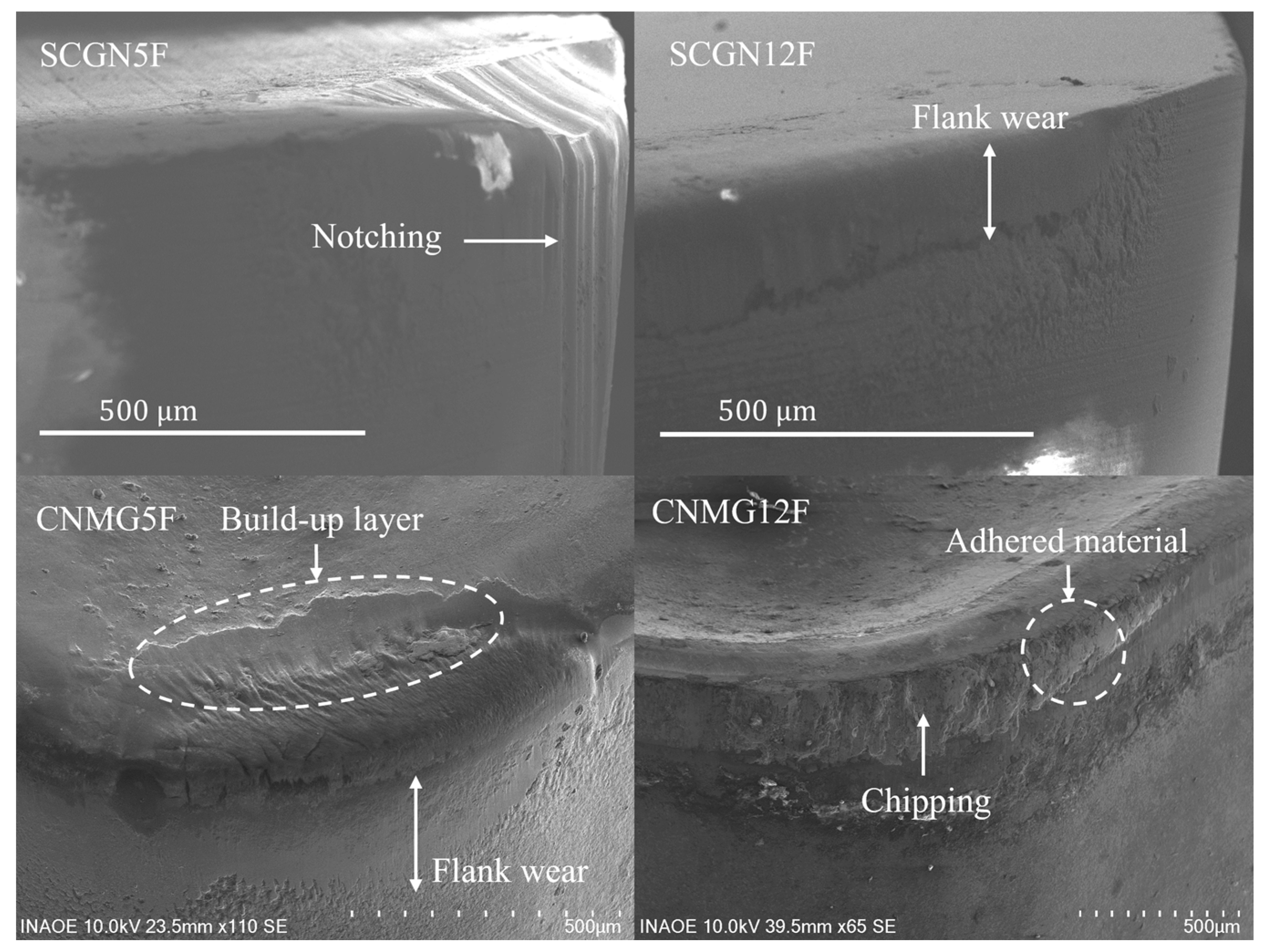
  • The flank and rake face of the ceramic inserts showed abrasion (notching) as the main wear mechanism, which was more evident in relation to the age−strengthening variation of GCI. In contrast, the coated carbide inserts exhibited a predominantly adhesive wear and oxidation on the rake face, compared to the other wear mechanism. The oxidation resulted in wear products such as aluminum oxide and iron oxide, which were deduced from the quantitative EDS analysis on the rake face of CNMG tools.
  • Five and twelve days of aging in GCI affected 50% of the tool life of a coated carbide insert. Based on this, 1.2 mm was the highest flank wear measured by the SEM analysis.
  • From the data collected by AFM, it is possible to correlate the effect of the adhesive material on the cutting tool with the final surface. The machining of GCI with a coated carbide insert resulted in a slightly nonuniform topography in contrast to the ceramic cutting tool.
  • The authors suggest that twelve days of age strengthening would allow the use of a carbide insert with uniform wear damage when time is not an issue in the machining shop. Manufacturers should evaluate time and cost before selecting cutting tool materials.
This investigation helps to further understand the tool wear mechanisms of the two inserts that were analyzed when completing the machining of the 40 workpieces. Future research should be the analysis of the rate dependence of the cutting-edge wear on the cutting time.

Author Contributions

Conceptualization, G.M.M. and N.E.G.-S.; Methodology, J.F.M.; Validation, G.A.M.-H., A.M.-S., and A.C.P.R.; Formal Analysis, M.M.M.; Investigation, J.F.M. and A.C.P.R.; Resources, M.A.M.-M. and M.M.M.; Data Curation, A.M.-S.; Writing—Original Draft Preparation, G.M.M. and N.E.G.-S.; Writing—Review & Editing, G.M.M. and N.E.G.-S.; Visualization, M.A.M.-M. and G.A.M.-H.; Supervision, G.M.M. and N.E.G.-S. All authors have read and agreed to the published version of the manuscript.

Funding

This research received no external funding.

Institutional Review Board Statement

Not applicable.

Informed Consent Statement

Not applicable.

Data Availability Statement

Data will be made available on request, contacting to the corresponding author.

Acknowledgments

The authors would like to acknowledge the invaluable contributions made by Luis Alberto Reyes Calderón from an automotive brake disk manufacturer from Puebla, Pue. Gustavo Minquiz and J. Flores acknowledges VIEP-BUAP and Tecnológico Nacional de México (Grant No. 18862.23-P).

Conflicts of Interest

The authors declare no conflict of interest.

Abbreviations

GCIGray Cast Iron
CGICompacted Graphite Iron
EDS/EDXEnergy Dispersive X-ray
As-castCondition of a metal casting without heat treatment
CBNCubic Boron Nitride
PCBNPolycrystalline Cubic Boron Nitride
UTSUltimate Tensile Strength
BCBNBinderless Cubic Bore Nitride
BUEBuild-Up Edge
BNDCCBoron Nitride Dispersed Cemented Carbide
SEMScanning Electron Microscopy
AFMAtomic Force Mircroscope
CVDChemical Vapor Deposition
SCGNCeramic inserts used in this work
CNMGCoated carbide inserts used in this work
VCCutting speed
fnFeed per revolution
aPDepth of cut

References

  1. Rassini, S.A.B. de C.V. Reporte Anual 2018. 2018. Available online: https://www.bmv.com.mx/docs-pub/infoanua/infoanua_918598_2018_1.pdf (accessed on 31 July 2023).
  2. Durand-Charre, M. Microstructure of Steels and Cast Irons; Springer: Berlin/Heidelberg, Germany, 2003. [Google Scholar]
  3. Zhu, L.; Evans, R.; Zhou, Y.; Ren, F. Wear Study of Cubic Boron Nitride (cBN) Cutting Tool for Machining of Compacted Graphite Iron (CGI) with Different Metalworking Fluids. Lubricants 2022, 10, 51. [Google Scholar] [CrossRef]
  4. Collini, L.; Nicoletto, G.; Konecna, R. Microstructure and mechanical properties of pearlitic gray cast iron. Mater. Sci. Eng. A 2008, 488, 529–539. [Google Scholar] [CrossRef]
  5. Behnam, M.M.J.; Davami, P.; Varahram, N. Effect of cooling rate on microstructure and mechanical properties of gray cast iron. Mater. Sci. Eng. A 2010, 528, 583–588. [Google Scholar] [CrossRef]
  6. Dawson, S.; Popelar, P. Thermal Analysis and Process Control for Compacted Graphite Iron and Ductile Iron. United Kingdom. 2014. Available online: https://sintercast.com/media/2280/thermal-analysis-and-process-control-for-compacted-graphite-iron-and-ductile-iron.pdf (accessed on 31 August 2023).
  7. Pluphrach, G.; Teekasap, S.; Amornthatri, T.; Limboonruang, T.; Kharanan, T.; Pluphrach, K. Effects of cooling rate on impact properties and microstructure of gray cast iron ASTM A48. Songklanakarin J. Sci. Technol. 2022, 44, 929–935. [Google Scholar]
  8. Hurst, S. Metal Casting—Appropriate Technology in the Small Foundry, First. Southampton Row, London: Intermediate Technology Development Group. 1996. Available online: https://www.ptonline.com/articles/how-to-get-better-mfi-results (accessed on 24 August 2023).
  9. Richards, V.L.; Nicola, W. Final Technical Report: Age Strengthening of Gray Cast Iron Phase III. Produced Under Contract Number: DE-FC07-00ID13851, p. DOE/ID13851. 2003. Available online: https://www.osti.gov/servlets/purl/812004 (accessed on 31 August 2023).
  10. Alexis, V.; Frédéric, R.; Jean, Q.; Eric, A. Determination of Gray Cast Iron Age Strengthening by Nondestructive Methods: Effect of Alloying Elements. J. Mater. Eng. Perform. 2019, 28, 4026–4033. [Google Scholar] [CrossRef]
  11. Kountanya, R.K.; Boppana, P. Optimization of machining of automotive components with polycrystalline cubic boron nitride. Proc. Inst. Mech. Eng. Part B J. Eng. Manuf. 2008, 222, 797–805. [Google Scholar] [CrossRef]
  12. Ebner, R. Influence of Aging, Sampling Site and Machining of Test Specimens Upon Tensile Strength and Hardness of Grey Cast Iron. BCIRA 1963, 50, 689–691. [Google Scholar]
  13. Richards, V.L. AGE-strengthening of cast iron and its effects on machinability: Review of the literature. In Advances in the Science and Engineering of Casting Solidification: An MPMD Symposium Honoring Doru Michael Stefanescu; TMS Annual Meeting 2015-March; Wiley: Hoboken, NJ, USA, 2015; pp. 269–276. [Google Scholar] [CrossRef]
  14. Teague, J.; Richards, V. Age strengthening of cast irons: Review of research and literature. Int. J. Met. 2010, 4, 45–57. [Google Scholar] [CrossRef]
  15. Leslie, W.C. The Physical Metallurgy of Steels; TechBooks: MI Michigan, USA, 1981. [Google Scholar]
  16. Anish, T.; Lekakh, S.N.; Richards, V.L. 08-063 The Effect of Ti and N on Iron Age Strengthening. Trans. Am. Foundrymen’s Soc. 2008, 116. [Google Scholar]
  17. Fall, I.; Genin, J.M.R. Mössbauer spectroscopy study of the aging and tempering of high nitrogen quenched Fe-N alloys: Kinetics of formation of Fe16N2 nitride by interstitial ordering in martensite. Metall. Mater. Trans. A Phys. Metall. Mater. Sci. 1996, 27, 2160–2177. [Google Scholar] [CrossRef]
  18. Anish, T.V. Age Strengthening of Gray Cast iron: Alloying Effects and Kinetics Study. Missoury University. 2007. Available online: https://scholarsmine.mst.edu/masters_theses/4554/ (accessed on 24 August 2023).
  19. Stephenson, D.A.; Agapiou, J.S. Metal Cutting Theory and Practice, Third; CRC Press: Boca Raton, FL, USA, 2016. [Google Scholar]
  20. Smith, G.T. Cutting Tool Technology; Springer: London, UK, 2008. [Google Scholar]
  21. de Sousa, J.A.G.; Sales, W.F.; Machado, A.R. A review on the machining of cast irons. Int. J. Adv. Manuf. Technol. 2018, 94, 4073–4092. [Google Scholar] [CrossRef]
  22. Yin, G.; Shen, J.; Wu, Z.; Wu, X.; Jiang, F. Experimental Investigation on the Machinability of PCBN Chamfered Tool in Dry Turning of Gray Cast Iron. Processes 2022, 10, 1547. [Google Scholar] [CrossRef]
  23. Wojciechowski, S.; Talar, R.; Zawadzki, P.; Wieczorowski, M. Evaluation of physical indicators and tool wear during grooving of spheroidal cast iron with a novel WCCo/cBN (BNDCC) inserts. Wear 2020, 454–455, 203301. [Google Scholar] [CrossRef]
  24. Sayit, E.; Aslantas, K.; Çiçek, A. Tool wear mechanism in interrupted cutting conditions. Mater. Manuf. Process. 2009, 24, 476–483. [Google Scholar] [CrossRef]
  25. Schultheiss, F.; Bushlya, V.; Lenrick, F.; Johansson, D.; Kristiansson, S.; Ståhl, J.E. Tool wear mechanisms of pcBN tooling during high-speed machining of gray cast iron. Procedia CIRP 2018, 77, 606–609. [Google Scholar] [CrossRef]
  26. Chen, J.; Liu, W.; Deng, X.; Wu, S. Tool life and wear mechanism of WC-5TiC-0.5VC-8Co cemented carbides inserts when machining HT250 gray cast iron. Ceram. Int. 2016, 42, 10037–10044. [Google Scholar] [CrossRef]
  27. Pereira, A.A.; Boehs, L.; Guesser, W.L. The influence of sulfur on the machinability of gray cast iron FC25. J. Mater. Process. Technol. 2006, 179, 165–171. [Google Scholar] [CrossRef]
  28. Tooptong, S.; Park, K.H.; Lee, S.W.; Kwon, P.Y. A Preliminary Machinability Study of Flake and Compacted Graphite Irons with Multilayer Coated and Uncoated Carbide Inserts. Procedia. Manuf. 2016, 5, 644–657. [Google Scholar] [CrossRef]
  29. Angseryd, J.; Coronel, E.; Elfwing, M.; Olsson, E.; Andrén, H.O. The microstructure of the affected zone of a worn PCBN cutting tool characterised with SEM and TEM. Wear 2009, 267, 1031–1040. [Google Scholar] [CrossRef]
  30. Herwan, J.; Misaka, T.; Kano, S.; Sawada, H.; Furukawa, Y.; Ryabov, O. Improving Sustainability Index of Grey Cast Iron Finish Cutting Through High-Speed Dry Turning and Cutting Parameters Optimization Using Taguchi-Based Bayesian Method. Int. J. Precis. Eng. Manuf. Green Technol. 2022, 10, 729–745. [Google Scholar] [CrossRef]
  31. ISO 3685:1993; Tool-Life Testing with Single-Point Turning Tools. International Organization for Standardization: London, UK, 1993; p. 48.
  32. Tungaloyamerica. TurnLine—T515- New Grade for Cast Iron Turning. 2017. Available online: https://tungaloy.com/wpdata/wp-content/uploads/433-u_T515.pdf (accessed on 24 August 2023).
  33. GmbH, C. Ceramic insert for Turning, Grooving and Milling. Germany. 2023. Available online: https://www.ceramtec.com/files/wz_ceramic_inserts_en.pdf (accessed on 24 August 2023).
  34. Coromant, S. Training Handbook—Metal Cutting Technology. Swedden. 2017. Available online: https://www.sandvik.coromant.com/en-gb/search?q=C-2920-40-2&generalRefiners=%7B%7D (accessed on 31 August 2023).
  35. Sobiyi, K.; Sigalas, I.; Akdogan, G.; Turan, Y. Performance of mixed ceramics and CBN tools during hard turning of martensitic stainless steel. Int. J. Adv. Manuf. Technol. 2015, 77, 861–871. [Google Scholar] [CrossRef]
  36. Nicola, W.M.; Richards, V.; Edington, J. Age Strengthening of Gray Cast Iron: Nitrogen Effects and Machinability. Master’s Thesis, Missouri University of Science and Technology, Rolla, MO, USA, 2002. [Google Scholar]
  37. Fundamental, S. Encyclopedia of Tribology. Springer: Berlin/Heidelberg, Germany, 2013. [Google Scholar] [CrossRef]
  38. Guo, X.; Chen, L.; Zhao, W.; Wan, H.; Wen, H.; Zhou, J. Machinability study on dry machining of white cast iron by polycrystalline cubic boron nitride inserts. Mach. Sci. Technol. 2022, 26, 137–159. [Google Scholar] [CrossRef]
Figure 1. Solidification rate for the Fe-4.28C eutectic composition [2].
Applsci 13 10248 g001
Figure 2. Methodology for brake disk and tool wear analysis: (a) brake machining process; (b) characterization and analysis.
Applsci 13 10248 g002
Figure 3. (a) Brake disk geometrical features; (b) area machined.
Applsci 13 10248 g003
Figure 4. Gray cast iron showing a flake graphite morphology, unetched.
Applsci 13 10248 g004
Figure 5. EDS Map of GCI.
Applsci 13 10248 g005
Figure 6. Tool wear analyzed by optical microscope.
Applsci 13 10248 g006
Figure 7. SEM micrograph of cutting tool flank wear.
Applsci 13 10248 g007
Figure 8. SEM micrograph of cutting tool rake face.
Applsci 13 10248 g008
Figure 9. EDS spectrum of rake face of ceramic and coated carbide cutting tool.
Applsci 13 10248 g009
Figure 10. Surface topography of the workpiece machined with 12 days of aging: (a) ceramic insert, (b) coated carbide insert.
Applsci 13 10248 g010
Table 1. Tool data.
Table 1. Tool data.
Indexable insert cutting tool:
  • - CNMG120412TSF- T515 Coated Carbide Grade (CVD), (Coated Carbide, Tungaloy, Fukushima, Japan)—ISO Range—(K15) Effective cutting edge: 4, Chip breaker: 13-degree Rhombic insert, 80-degree with hole, Corner radius: 1.2 mm, Negative relief angle. Cost: 15 USD
  • - SCGN090412E-F Grade: SL 500, (Ceramic,CeramTec,Plochingen, Germany). Clearance angle major: 7-degree, Effective cutting edge: 4 Corner radius: 1.2 mm. Cost: 21 USD
Table 2. Configuration of cutting parameters.
ToolInsertrpmvc (m/min)fz (mm)
1CNMG120412TSF-T5156507240.1
2SCGN090412E-F100011150.1
Table 3. Gray cast iron characterization.
Workpiece MaterialGrey Cast Iron
5 days aging12 days aging
Hardness183 HB184.2 HB
Tensile strength (N/mm2)177 180
Chemical composition (at.%)CSiPMnSMoCrCuNiSnTi
3.82.440.010.650.110.010.230.050.020.09001
Table 4. EDS analysis of rake face and flank wear.
SCGN5RSCGN5FSCGN12RSCGN12FCNMG5RCNMG12R
Element at. (%)Elementat. (%)Elementat. (%)Elementat. (%)Elementat. (%)Elementat. (%)
C
N
O
Mg
Al
Si
Zn
Mo
41.61
20.50
32.40
1.78
0.21
2.75
0.01
0.14
C
O
Al
Si
Zn
75.70
22.46
0.11
1.52
0.21
C
N
O
Mg
Al
Si
Mo
54.97
3.57
39.28
1.68
0.02
0.39
0.07
C
O
Mg
Al
Si
Mn
Fe
Zn
Mo
17.75
10.33
0.91
5.46
32.46
15.45
15.56
0.20
1.90
C
O
Mg
Al
Si
Fe
Zn
Mo
16.04
52.15
0.10
27.40
0.63
3.65
0.01
0.03
C
O
Mg
Al
Si
Fe
Mo
5.14
69.83
3.28
2.28
2.48
15.68
1.31
Disclaimer/Publisher’s Note: The statements, opinions and data contained in all publications are solely those of the individual author(s) and contributor(s) and not of MDPI and/or the editor(s). MDPI and/or the editor(s) disclaim responsibility for any injury to people or property resulting from any ideas, methods, instructions or products referred to in the content.

