
A Novel Active Control Strategy with Decentralized Decoupling and Wavelet Packet Transformation: Design and Verification


1
Navy Submarine Academy, Qingdao 266199, China
2
Key Laboratory of Noise and Vibration Research, Institute of Acoustics, Chinese Academy of Sciences, Beijing 100190, China
3
Naval Research Institute, Beijing 100161, China
4
Department of Mechanical and Electrical Engineering, Ocean University of China, Qingdao 266100, China
*
Authors to whom correspondence should be addressed.
Appl. Sci. 2021, 11(8), 3554; https://doi.org/10.3390/app11083554
Submission received: 17 March 2021
/
Revised: 11 April 2021
/
Accepted: 12 April 2021
/
Published: 15 April 2021
(This article belongs to the Section Acoustics and Vibrations)
Abstract
:Featured Application
There is always complexity of the reference signal andpath coupling in underwater vehicles, whichcan reduce the convergence speed and stabilityof the active vibration control(AVC) algorithm. In this paper, a novel adaptivestrategy is proposed, called the WPTDDM-FxLMS algorithm, to solve the problemsmentioned above. The wavelet packet transformation is used to convert the multi-frequency reference signal into the line spectrum signals in multiple non-overlapping frequency bands, and the decoupling feedback compensation factors are introduced into the identification model of the secondary path, then the multi-input and multi-output system (MIMO) system can be simplified into a parallel SISO system; all of which will weaken the multi-path coupling effect by the simulation and experiments. Consequently, the novel algorithm is suitable for solving theMIMO vibration problemswith multi-frequency excitation and multi-path coupling in underwater vehicles.
Abstract
Active vibration control (AVC) can solve many vibration problems. However, structural vibration in underwater vehicles often involves other factors such as complex excitation and path coupling, etc. At present, the traditional algorithm (e.g., multi Filtered-x Least Mean Square, M-FxLMS) usually cannot effectively process the multi-frequency excitation and the coupling effects of the multi-secondary path, which will affect its convergence and stability to a certain extent. Consequently, a novel strategy is presented in this paper, namely, the wavelet packet transformation decentralized decoupling M-FxLMS algorithm (WPTDDM-FxLMS), which can solve the structural vibration problems mentioned above. The multi-frequency control is converted into a single-frequency line spectrum control, and the feedback compensation factor is introduced in the identification of the secondary path, both of which can simplify the multi-path control system to the parallel single-path systems. Furthermore, the WPTDDM-FxLMS algorithm is applied to the AVC in a multi-input and multi-output system (MIMO) vibration platform. Finally, the simulation and experiments show that the wavelet packet can decompose the multi-frequency excitation into a line spectrum signal, and the improvement of the decentralized decoupling and the variable step-size can effectively reduce the computation amount and increase the convergence speed and accuracy. Overall, the novel algorithm is significant for multi-path coupling vibration control. It will have certain engineering application value in underwater vehicles.
1. Introduction
As is well known, active vibration control (AVC) is an ideal way to solve vibration problems and has great significance for reducing radiated noise caused by the vibration of underwater vehicles. It has also been applied in other various fields such as anti-seismic engineering and instrument manufacturing [1,2]. Currently, this technology has attracted more attention as an important means to control radiation noise, especially in vibration noise control for underwater vehicles [3,4,5]. For example, the USA had developed an active noise and vibration control system, which could implement active vibration isolation for all low-frequency vibrations below 100 Hz and has been equipped in the latest Sea Wolf class nuclear submarines to achieve good acoustic stealth performance [6,7]. At the same time, the research department has also converted the AVC into civilian technology [8]. Australia has also applied it to effectively reduce the radiation noise in the power system of the Collins class submarine [9]. The UK has carried out AVC experiments on minesweepers with a better noise reduction effect [10]. The Defence Research Establishment Atlantic of Canada had also conducted a large number of studies on AVC in submarine [11]. The University of Karlskrona Ronneby in Sweden has developed an active and passive hybrid vibration isolation device and applied it to frigates, which could effectively isolate the acoustic radiation noise caused by the shell structural vibration [12,13]. The Paulstra Vibrachoc company in France also developed the AVC system for large equipment such as main engines and diesel engines, which have quite a significant damping effect [14]. Yang has retrofitted an active vibration isolation system to a diesel generator set to determine the effectiveness in a tugboat, and the experiments show that the combination of the active control system and the passive isolators is effective in reducing the global vibration and the acoustic pressure at the hydrophone position [15]. In addition, the Institute of Sound and Vibration Research (ISVR) and other institutes have also achieved many fruitful research results with AVC in underwater vehicles.
As mentioned above, AVC has been investigated in underwater vehicles research, but there are still many improvements in practical applications that need to be studied urgently, such as multi-path coupling control and processing for complex signals, etc. At present, this technology has been extensively studied in the single-input and single-output system referred to as SISO [3,16,17], where an finite impulse response or infinite impulse response (FIR/IIR) filter is used as a structure controller, and its weight coefficient is adjusted by the least mean squares or recursive least squares (LMS/RLS) criterion to minimize the positional response to a certain point. Ein particular, the adaptive filtering algorithm based on the Least Mean Square (LMS), simply called Filtered-x LMS (FxLMS), is commonly used in vibration and noise control [15,18,19]. On this basis, Huang [20], Wang [21], Yin [22], and Ma [23] proposed several improved algorithms such as FuLMS, MRFx-Newton, and Fx-FONLMS, etc. They also analyzed with these algorithms the calculation amount, execution efficiency, and control effect. Indeed, most of them were improved based on the LMS or RLS algorithms. In particular, the former is widely used due to its simple structure and easy implementation. However, this method mainly controlled a single measuring point; its overall control effect is not obvious to the structural vibration response in underwater vehicles, and it also heavily relies on the stability of the input signal. In this case, when the vibration source excitation is a stable narrow-band signal, the control performance will be much better. Unfortunately, the actual vehicle vibration is always affected by some factors such as equipment excitation, structural coupling and, basic interference, and the signal components of vibration source are often very complicated, which may affect system stability. Moreover, when those signals are transferred to the error sensor by the multi-secondary path coupling, the pick-up signal of one sensor often contains the responses of all control signals to this one. Thus, the AVC in the multi-input and multi-output system (MIMO) had no essential differences from SISO, and the traditional algorithms have some problems such as slow convergence, insufficient stability, or even divergence, which caused its engineering applications to be constrained [15,24]. In addition, for the complicated frequency component in the vibration source, frequency-selective filtering and adaptive band-stop filtering are often used to realize the narrow-band signal separation, and then the active control is applied.
Moreover, for the problem of structural vibration, the single actuator control and error sensor evaluation constantly face difficulties in meeting with the vibration control requirements. Usually, multiple actuators and multiple error sensors are introduced to carry out multi-path control and obtain a better overall control. At this time, the coupling effect of each secondary path will directly affect the convergence performance and control effect, and generally, the centralized or decentralized methods can be used for its compensation [25,26,27]. Among them, the update for any control filter of the former requires all error signals, and its calculation amount is very large, which easily reduces the stability and real-time performance [28]. Corresponding to the former, the coupling effect between the actuator and the non-proximity sensor in secondary path is simply ignored by the latter, and if the phase difference between the identification secondary path and the actual secondary physical path is more than 90°, the controller will iterate in the wrong direction and eventually lead to failure [16,29]. Usually, the phase difference of the former is very large [30], and the latter is prone to frequency mismatches [31], all of which could cause difficulties in engineering applications.
Fortunately, studies have shown that [32,33,34,35,36] wavelet packet transform can quickly convert signals into time-domain signals with different frequency components, which can effectively solve the extraction problems of the complicated signal, and has been applied to signal filtering and denoising such as wavelet neural network fault diagnosis, motor servo control, etc. Therefore, it is necessary to design a more efficient and stable control strategy for an MIMO system with multiple sensors and complicated excitations, which can effectively reduce the radiated noise caused by structural vibration in underwater vehicles. In this paper, based on the traditional M-FxLMS algorithm, the wavelet packet transform is firstly applied to preprocess the complicated reference signal and extract its frequency characteristic, and the feedback compensation factor is introduced to recompense the coupling effect of the secondary path between the actuator and the non-proximity sensors. Then, the independent step-size is also designed for the controller, and the system will be simplified to a parallel control structure of the component subsystem for each frequency band; thus, the WPTDDM-FxLMS algorithm is proposed. Finally, the simulation and experiment also explore the multi-path active control effect in multi-frequency excitation.
The remainder of this paper is divided into six sections. Section 2 gives the traditional algorithm. Section 3 carries out the design and analysis for the WPTDDM-FxLMS algorithms. Section 4 presents the numerical simulations for the traditional and the novel algorithms with a complex reference signal and secondary-path coupling. Section 5 conducts the experimental research. Section 6 briefly concludes and discusses the paper.
2. The M-FxLMS Algorithm
Figure 1 shows the MIMO system schematic diagram of a simplified double-layer vibration isolation platform in underwater vehicles. The upper is the vibration source equipment and platform, which includes the complicated periodic excitation.
There are H electromagnetic active and passive integrated vibration isolators installed between the upper and middle rack; these isolators can also be called actuators, where H, an even number, is equal to 4 in Figure 1. The middle platform is a flexible floating raft, fixed on the structure foundation by H rubber vibration isolators in an underwater vehicle. The reference sensor is located at the foot of the vibration source device, and the H error sensors are at the foot of the vibration isolators in the middle platform, where the left front (or rear) and right front (or rear) positions in the Figure 1 are 1#, 3#… (H/2 + 1)#, 2#, 4#… H# error sensors, respectively. These error sensors are used as control targets, and the active control forces are exerted by the H integrated vibration isolators, all of which can achieve global control for the vibration isolation platform.
Aimed at the platform in Figure 1, the multi-path algorithm diagram is shown in Figure 2, where the thick lines represent matrix operations, and the multi-path control system only collects one reference signal, which contains all complicated excitation frequency components. Additionally, the platform also contains H error sensors, actuators, and error signals, which means the system consists of primary paths, and each path is represented by the order FIR filter. At the same time, it also includes secondary paths; each of them is represented by with the order FIR filter, and each path control filter is the order FIR filter. It is assumed that the reference input signal, the desired signals, the error signals, and the control signals are represented by the matrix as , , and at the moment, respectively. And the acceleration values of the measuring point #1, #2, #3, #4 are used to evaluate the control effect of the system Thus, the reference signal and the transfer matrix of the secondary path can be expressed as
where , the transfer function is H × H dimensional matrix, and each secondary path represents the transfer function between the h-th actuator and the i-th error sensor. Then, the error matrix can be obtained as
where , and the component-wise of the error signal can be represented as
where is the output of the i-th control filter, and is the i-th weight coefficient of the controller, all of which can be expressed, respectively, as follows:
To minimize the vibration delivered to the base, the sum squares of all errors should be minimized in the middle structure. Thus, the system objective function will be expressed as
According to the steepest descent principle [27], the iterative law can be derived as
where is filtered by the secondary path estimation matrix with the reference input signal, and Equation (8) is the iterative law of the adaptive filtering algorithm for the MIMO system, called the multi-Fxlms algorithm (M-FxLMS). Obviously, the weight vector iteration of each control filter needs all error signals at the same time, which can not only increase the system computation amount but the anomalies of any control output signal will also affect other error signals and may cause the entire controller to diverge. Therefore, it is necessary to improve this strategy to achieve global control, which can make one fault without affecting the resolution of the other paths, and it is more conducive to solving the problem of path coupling vibration.
3. Design and Analysis for WPTDDM-FxLMS Algorithm
3.1. Decentralized Decoupling Improvement for the Secondary Path
It can be seen from Figure 2 and Equation (8) that the traditional M-FxLMS algorithm has certain disadvantages. Assuming the system is fully decoupled, the update for each controller is only related to its corresponding error signal, which means that the non-diagonal elements in secondary path will be ignored. This simplification process is shown in Equation (9); the actual secondary path first evolves into an estimated secondary path , and then the off-diagonal elements are omitted and further simplified into the matrix . Thus, if is used to represent the estimated value of the transfer function in secondary path, the matrix can be written as the diagonal matrix form:
Then, the error signal shown in Equation (4) can be updated and rewritten as
According to the steepest descent principle, the update rules of the k -th control filter can be obtained as follows:
Indeed, the error signal is still the output result of the secondary path by all actuators mentioned in Figure 1. Assuming that the controller has an optimal solution after convergence, substituting Equation (3) into Equation (12), the following can be obtained:
where if Equation (13) is convergent, there is when . In other words, the optimal solution can be expressed as
By subtracting the optimal solution into both ends of Equation (13), the following can be obtained:
It can be obtained from Equation (15) that if only the eigenvalue modulus of the matrix is less than 1, the controller would be in a converged state. Otherwise, the system will be in a divergent state, which is mainly because since the coefficient is not always zero, it depends on factors such as system input, secondary paths, and step size, etc. It is also obtained from Equation (9) that the decentralized adaptive control ignores the non-diagonal elements of the identification matrix in secondary path, and its convergence is related to the when the iterative step-size and the input signal are definite. Therefore, in order to reduce or even ignore the adverse effects of the non-diagonal elements, the non-diagonal element can be compensated to the coupling feedback of each main transmission paths. Then, assuming the k-th main diagonal element in can be expressed as
where is a compensation factor of the coupling feedback, it can be described as
In Equations (16) and (17), the non-diagonal element is compensated to the main secondary path, which can effectively accelerate the system convergence speed, reduce the calculation amount, and improve the system stability. Then, substituting Equation (16) into Equation (11), the update rules of the k-th control filter can be updated as follows:
Thus, it can be observed from the analysis of Equations (8) and (18) that it should not simply ignore the error transmission between the actuator and the non-proximity sensor. Equation (18) introduces non-diagonal elements, which is closer to the real situation. The compensation feedback factor, introduced to improve the decentralized control algorithm, has a higher identification accuracy than ignoring the non-diagonal elements and can effectively reduce the calculation amount. Moreover, only a solitary point error signal is needed, which also expands the data range of the iterative step size and improves the convergence speed.
3.2. Signal Extraction of Wavelet Packet Transformation
In Section 3.1, the adaptive algorithm complexity in the MIMO system is significantly reduced, and the decentralized decoupling of the secondary path is also improved. However, the vibration source signal in underwater vehicles is very complicated, which has an influential impact on the control strategy; as shown in Equation (15), the input signal affects the convergence characteristics of the system to a certain extent. Theoretically, if the complicated input signal could be effectively decomposed into multiple narrowband signals, then the segmentation control may achieve a better control effect. Research has shown that [37] the wavelet packet transform can decompose the complicated input signals into multiple non-overlapping and narrower-frequency bands. This method can synchronously decompose the scale space and the wavelet space, which has a high resolution for the high-frequency section. Assuming that and an orthogonal scaling function is in space , there is a two-scale formula [38]:
where and is an orthogonal wavelet function. For a set of best orthogonal wavelet bases in , the space could be decomposed into
If the continuous time function is , the projection coefficient for on the orthogonal basis of can be written as
Similarly, the orthogonal basis projection coefficient for is in each subspace , which is called the orthogonal wavelet packet transformation of . Actually, the orthogonal wavelet packet transform will be expressed in a recursive form .
where and can be regarded as low-pass filtering and high-pass filtering coefficients. The band number of the wavelet packet decomposition depends on its decomposition scale , and represents the (n + 1)-th frequency band on the m-th layer, , where and m is the wavelet decomposition layer number. Assuming that is the sampling frequency of the input signal, it can be detected for the frequency band (0~) by the Nyquist principle, and the bandwidth of each frequency band in the m-th layer is .
3.3. Algorithm Design for WPTDDM-FxLMS
In Section 3.2, complex signals will be decomposed into multiple single frequency line spectrum signals by the wavelet method mentioned in Equations (19)–(24), and then the MIMO system will be transformed into a parallel SISO subsystem. It is assumed that the input signal can be decomposed into time-domain signals ,, by passing the wavelet packet function , and all of them do not overlap with each other in different frequency bands. If each frequency band is in parallel and can operate independently, ,, and are the controller output signal, error signal, and iteration step size for the h-th path of the j-th frequency band, respectively. Then, the h-th path total output will be elucidated as
Then, the h-th error signal also can be expressed as
According to the steepest descent principle, the minimum response of the error sensor is regarded as the objective function. Thus, Equation (18) will be upgraded, and then the update rule of each path control filter in the j-th frequency band can be obtained as follows:
where is an iterative step-size, the filtered reference signal is filtered by the diagonalization identification matrix , and is also transformed from the error signal by the wavelet packet, which can be expressed as
In addition, in order to obtain the optimal control effect, the reference and the error signals can be introduced to correct the step-size, which can achieve a faster convergence speed with a large step-size in the early stage and a smaller steady-state error with a small step-size later. Then, the corrected iteration step-size can be rewritten as
For the determined transfer function in the secondary path and the reference input signal, the controller convergence speed can be guaranteed by adjusting the iteration step-size; if the step-size is too small, the convergence performance will also be reduced. Thus, the control signal for each path on the j-th frequency band subsystems will be expressed as
Based on the above, Equations (27)–(32) present the controller updating law, the filtered reference signal, and the iterative step-size, and the output can update for each path on the j-th frequency band; the specific process and structure are shown in Figure 3 (H is equal to four), a novel improved control strategy, referred to as the WPTDDM-FxLMS algorithm. The line spectrum signal controller of the j-th frequency band can be called the control subsystem of the j-th frequency band. This algorithm will quickly acquire the frequency characteristics of the complicated signal by the wavelet packet transform, effectively suppressing the path coupling by the feedback compensation and decomposing it into multiple narrowband control signals at the same time. Therefore, it will have a higher computational efficiency, complex signal processing, and coupled vibration control capabilities and can be applied to active vibration control in MIMO systems.
4. Selection and Simulation Analysis for Wavelet Packet
4.1. Selection of the Best Wavelet Packet Base
According to the wavelet packet decomposition in Equations (19)–(24), the decomposition effects of the reference signal for different wavelet packet bases are also different. In order to effectively decompose the complicated signal into the narrowband line spectrum signals with different frequency bands, a complex excitation is used as the input signal, which contains 37 Hz, 60 Hz, and 110 Hz signals with white noise. In the process, the distribution should be balanced and there is no significant endpoint effect, and the energy needs to be concentrated as much as possible. Based on the different natures of the wavelet base, the Haar, db, sym, and bior wavelet bases are used, respectively. The number of decomposition layers is five layers; the frequency band is 32 layers. Then, the decomposition effect is illustrated in Figure 4, Figure 5, Figure 6, Figure 7, respectively.
It can be observed in Figure 4 that the energy spectrum of the frequency band is relatively divergent by the Haar wavelet, and the maximum energy is only 14.5. The energy spectrum in frequency bands 2, 3, 4, 6, and 7 is much higher, and the energy is also divided into four or even five frequency bands. Evidently, this decomposition signal does not effectively realize the separation of the tri-band line spectrum signal. In Figure 5, the energy spectrum is concentrated in frequency bands 3, 4, 6, and 7; the maximum was up to 24, and the energy spectrum of the other frequency bands is lower. Thus, the db5 wavelet is much better than the Haar wavelet.
In Figure 6, the energy is concentrated in three effective frequency bands (3, 4, and 6), and the energy spectra of other frequency bands are very low. The line spectrum performance is very prominent and more convenient to control. In Figure 7, the energy spectrum is highly concentrated in three frequency bands (2, 3, and 5), but the energy of the low-frequency line spectrum is too small; thus, it is obviously not adverse for AVC implementation. Depending on the analysis above, the sym20 can be the optimal wavelet packet for decomposing the tri-band signal mentioned above.
4.2. The AVC Simulation Analysis for MIMO System
In Section 4.1, the optimal wavelet base of the multi-frequency input signal is chosen by simulation. On this basis, in order to verify the effectiveness and control effect of the M-FxLMS and WPTDDM-FxLMS algorithms, the vibration isolation platform in Figure 1 is taken as the research object, and the offline identification is carried out to acquire four primary paths and sixteen secondary paths, and these models are 500-order and 128-order FIR filters, respectively. In this process, in order to improve identification accuracy and speed up convergence, a low-band white noise excitation is input to the upper-layer exciter and the four integrated actuators in sequence, and the noise and the error signals are synchronously collected. The identification results are presented in Figure 8 and Figure 9, respectively.
Based on the above analysis, the ,, , and are the identification results for the primary path in Figure 8, and the other ones are shown for the secondary path in Figure 9. Among them, is the coupled secondary path between the j-th actuator and the i-th error signal. Obviously, the ,, , and coefficients of the main secondary path are slightly larger than those of the other non-adjacent secondary path, so the main diagonal identification for the secondary paths dominates the control process. However, the coupling effects of other non-adjacent secondary paths also cannot be overlooked, which is caused by the coupling effect between the non-proximity sensors and actuators. On this basis, with the combination of the offline identification in Figure 8 and Figure 9, the numerical simulations are carried out to verify two algorithms with the sym20 wavelet base and 37 Hz/60 Hz/110 Hz excitation comprising white noise, and the control effect in 1#–4# error signals are shown in Figure 10, Figure 11, Figure 12, Figure 13 and Table 1 below.
Figure 10, Figure 11, Figure 12, Figure 13 show the comparisons in error signals 1#–4# for passive vibration isolation, the M-FxLMS and the WPTDDM-FxLMS algorithms, respectively. Table 1 shows the damping effect for each line spectrum. It can be seen that two algorithms have a certain effect on the time domain, while the coupling paths led to a slowing convergence and an inconspicuous control effect for the traditional algorithm on each measurement point. In particular, the vibration is even intensified in error signal 1#, which is mainly due to the failure of the 60 Hz and 110 Hz line spectrum vibration. Compared with passive vibration isolation, the traditional algorithm obtains 7.14 dB, −1.55 dB, −2.37 dB; 9.70 dB, 5.70 dB, 5.99 dB; 7.14 dB, 8.76 dB, 10.73 dB; and 9.61 dB, 1.47 dB, 3.05 dB at the three line spectrum in each error signal, respectively. While the improved algorithm obtains 14.97 dB, 27.86 dB, 21.14 dB; 21.05 dB, 36.16 dB, 32.52 dB; 16.96 dB, 33.58 dB, 29.52 dB; and 16.98 dB, 20.27 dB, 20.39 dB, respectively.
Obviously, the M-FxLMS algorithm has a better effect at 37 Hz in error signals 1#–4#, while its effect at 60 Hz and 110 Hz is more general. The average attenuation is 8.39 dB, 3.59 dB, and 4.35 dB in the three line spectrum. Correspondingly, the WPTDDM- FxLMS algorithm has compensated for the path secondary coupling and simplified the system into a parallel single-path control loop; every error signal has a better control effect. The average attenuation is 17.49 dB, 29.46 dB, and 25.89 dB in the three line spectrum, respectively. Therefore, its effect is almost an order of magnitude higher than that of the M-FxLMS algorithm, and it also has a faster convergence speed and better effect than the traditional algorithm. Therefore, theoretically, the improved algorithm is particularly suitable for solving complex excitation and coupled vibration control problems of underwater vehicles, which has been mentioned in Section 3.3.
5. Experimental Verification
In the Section 4, the active vibration control for the MIMO system has been simulated and analyzed. On this basis, a vibration isolation platform is built to further verify the control effect. The equipment mainly included an NI PXIe-8880 controller, a PXI-4498 input board, a PXI-6733 output board, a vibration exciter, a power amplifier, an acceleration sensor, and electromagnetic rubber active and passive hybrid integrated vibration isolator/actuators, etc. The platform installation is shown in Figure 14.
On the bottom of the platform, four BE85 rubber isolators are installed at each foot position; its lateral stiffness is much higher than the vertical stiffness, and its vertical stiffness, natural frequency, and damping ratio are 342 N/mm, 8.5 Hz, and 0.095, respectively. The actuators 1#–4# and the error sensors are installed in four foot positions of the platform. Among them, the actuator is a permanent magnet electromagnetic actuator, which can output the control force as the active component of the secondary path, and the BE85 rubber acted as the passive isolating component. The actuator is connected between the upper and middle platform by screws, and it only provided the vertical force to control the middle vibration. Therefore, in order to decrease the influence of the actuator output force on the control system, the response curves between the output force, the current amplitude, and the current frequency are obtained by 20–200 Hz and 2–9A current excitation, as shown in Figure 15. It could be seen that the actuator displacement is basically linear with the current amplitude where, in the same amplitude condition, the higher the frequency, and the smaller the output force.
In the experimental system, the excitation is 37 Hz, 60 Hz, and 110 Hz composite signals consistent with the simulation, and the identification values for sixteen offline secondary paths in Figure 9 are also introduced into the control algorithm. The sampling frequency is 1 kHz, and the sym20 wavelet base is used for the wavelet packet transformation with five layers. Then, the experiments are carried out by the M-FxLMS and the WPTDDM-FxLMS algorithm, respectively. During the test, the NI PXI-6733 D/A board card first sends an initial excitation to drive the vibration exciter by a power amplifier. At the same time, the upper and the middle acceleration sensors acquire the reference signal and four error signals; all of them will be converted by the PXI-4498 A/D board card to the PXIe-8880 controller. Then, the output signals are produced with the controller real-time decoding, and they are passed through the NI PXI-6733 D/A board card to drive the actuator and generate the dynamic control force. The specific control effects in measuring points 1#–4# are shown in Figure 16, Figure 17, Figure 18, Figure 19 and Table 2.
It could be seen from Figure 16, Figure 17, Figure 18, Figure 19 that acceleration is intensified for the M-FxLMS algorithm in point 1#; the other points are only slightly attenuated, and the time-domain control effect is not obvious enough. In addition, the 110 Hz line spectrum control fails in measuring point 1# in Table 2; its vibration is also intensified. In particular, the control induces a 73 Hz line spectrum. Whereas, in measuring point 2#, the 37 Hz and 60 Hz line spectrum had a certain effect, and the attenuation of the 110 Hz line spectrum reached 15.06 dB. Furthermore, the attenuation of 37 Hz line spectrum reached 10 dB in measuring point 3#; the 60 Hz and 110 Hz line spectra are both attenuated to some degree. Moreover, the 37 Hz line spectrum is obviously attenuated in measuring point 4#; the 60 Hz line spectrum is basically unchanged, while the 110 Hz line spectrum is intensified. In contrast, the improved algorithm can make the acceleration signal significantly reduced, and all of the three line spectra are obviously attenuated in points 1#–4#. Their average drops reach 17.93 dB, 15.19 dB, and 12.29 dB, respectively.
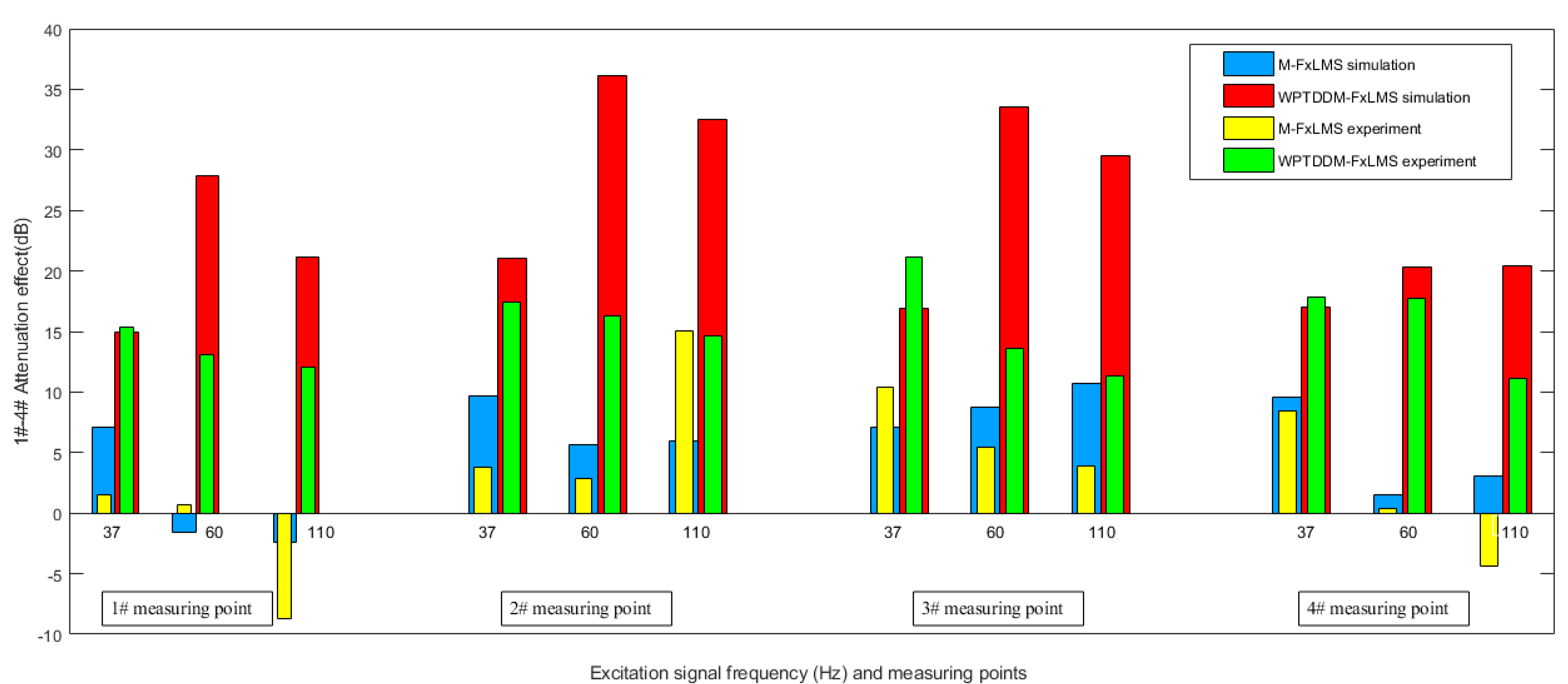
On the basis above, in order to further analyze the effects, the theoretical simulation and experimental verification will be comprehensively compared in Figure 20.
In general, it can be seen from Figure 20 that the simulation and experiment are basically consistent with each other, and the multi-line spectrum control effect of the novel algorithm is much better in terms of both simulation and experiment. In particular, the control effect is consistent with the simulation in low frequency, while the others are not better than the simulation in a slightly higher frequency, which indicates that the off-line identification does not contain sufficient frequency bands or the output capacity of the actuator is limited and the excitation amplitude is relatively small. In addition, the traditional algorithm has a certain effect on the excitation. However, the downside is that it excites other line spectrum signals in measuring point 1#. Overall, the updated algorithm has a better effect in each line spectrum and does not induce other line spectra. Therefore, the WPTDDM-FxLMS algorithm is more suitable in multi-frequency excitation and multi-path vibration isolation systems. In summary, the application value of the algorithm proposed in this paper is in good agreement with the theoretical research and experimental verification; it can be used as one of the effective methods to deal with the problem of active vibration control in underwater vehicles.
6. Conclusions and Discussion
This paper has proposed a novel algorithm to solve the complexity of reference signals and path coupling problems. The wavelet packet transform is used to convert the multi-frequency excitation into the line spectrum signals in multiple non-overlapping frequency bands, and the decoupling feedback compensation factors are also introduced into the identification model in the secondary path. All of them can simplify the multi-path system into parallel single-path systems, which can weaken the multi-path coupling effect with multi-frequency excitation. Overall, several conclusions can be drawn from the simulation and experiment:
- (1)
- When the excitation is 37 Hz, 60 Hz, and 110 Hz line spectrum signals with white noise, sym20 is the best wavelet packet decomposition base, which can provide more a stable and reliable line spectrum decomposition for the WPTDDM-FxLMS algorithm.
- (2)
- In multi-frequency excitation and multi-path systems, the traditional algorithm is still inadequate for AVC; some measuring points are basically in a failure state, and it is also much easier to induce other line spectrum signals and the stability is not perfect enough.
- (3)
- Decentralized decoupling improvement considers the impact of off-diagonal elements on system performance, increases the influence weight of the diagonal secondary paths, and it can also transform a complicated multi-frequency and multi-path coupling problem into a simple single-path control of the multiple parallel line spectrum signals.
- (4)
- The WPTDDM-FxLMS algorithm can effectively reduce the reference signal and the multi-path coupling effect on iterative step-size and stability, which has the characteristics of low computation mount, fast convergence speed, and high control precision, and the control effect of the multi-line spectrum is more obvious. Correspondingly, the novel algorithm is more suitable than the traditional one for solving the structural vibration control problems for multi-frequency excitation and multi-path coupling in underwater vehicles.
Although the algorithm proposed in this paper is well matched in theory and practice, there are still some issues to further research. For example, the choice of wavelet base has an important influence on the decomposition of the reference signal. The method in this paper can be mainly used for a relatively stable excitation signal. If the frequency of the excitation signal changes greatly, it is necessary to explore an adaptive wavelet strategy. On the other hand, if there are more line spectrum excitations and time-varying coupled secondary-paths, the algorithm needs to be further optimized and improved, especially for the vibration control of elastic structures.
Author Contributions
Conceptualization and methodology, L.Y. and W.G.; computer simulation, W.G. and B.Z.; software and validation, L.Y. and L.L.; experimental work, W.G., B.Z., and L.Y.; writing—original draft preparation, L.Y. and L.L.; writing—review and editing, J.Y. and B.Z.; supervision, W.G. All authors have read and agreed to the published version of the manuscript.
Funding
This work was supported by the National Natural Science Foundation of China (Grant no.51909267), the project ZR2019QEE031 by the Shandong Provincial Natural Science Foundation and the Fundamental Research Funds for the Central Universities (Grant no.201965006).
Institutional Review Board Statement
Not applicable.
Informed Consent Statement
Not applicable.
Data Availability Statement
All data included in this study are available upon request by contact with the author Weipeng Gao.
Conflicts of Interest
The authors declare no conflict of interest.
References
- Niu, J.; Song, K.; Lim, C. On active vibration isolation of floating raft system. J. Sound Vib. 2005, 285, 391–406. [Google Scholar] [CrossRef]
- He, L.; Xu, W. Naval vessel machinery mounting technology and its recent advances. Acta Acust. 2013, 38, 128–134. [Google Scholar]
- Sun, Y.P.; Sun, H.L.; Zhang, W.; Wang, H.; Yang, J. Experimental research into active control of low-frequency line spectral disturbances in liquid-filled pipe. Chin. J. Ship Res. 2017, 12, 122–127. [Google Scholar]
- Chen, D.L.; Chen, N. Active control of structural sound radiation in an acoustic enclosure consisting of flexible structure. J. Southeast Univ. 2014, 30, 318–322. [Google Scholar]
- Hill, S.G.; Tanaka, N.; Lwamoto, H. A generalized approach for active control of structural-interior global noise: Practical implementation. J. Sound Vibr. 2012, 331, 3227–3239. [Google Scholar] [CrossRef]
- Hamblen, N. Next generation stealth submarines. Sea Technol. 1998, 39, 59–62. [Google Scholar]
- Walrod, J. Sensor and Actuator Networks for Acoustic Signature Monitoring and Control; Undersea Defence Technology: Nice, France, 1999. [Google Scholar]
- Active Control Eliminates Noise or Unwanted Motion. 2003; pp. 11–23. Available online: http://endo.sandia.gov/9234 (accessed on 12 March 2021).
- Xun, L.; Cazzolato, B.S.; Hansen, C.H. Active vibration control of an intermediate mass: Vibration isolation in ships. In Proceedings of the Annual Australian Acoustical Society Conference, Adelaide, Australia, 13–15 November 2000; Volume 13, pp. 281–288. [Google Scholar]
- Submarine Acoustic Stealth Technology [DB]. 2003, pp. 11–30. Available online: http://bds.cetin.net.cn/yszbk/js/jsjs0062.htm (accessed on 12 March 2021).
- Akpan, U.O.; Beslin, O.; Brennan, D.P. Controller Technologies for Active Control of Low Noise and Vibration in Ship Structures; Process: CAN: Quebec, QC, Canada, 1999. [Google Scholar]
- Winberg, M.; Johansson, S.; Lagö, T.L. Active Control of Engine Induced Noise in Naval Application. Pediatr. Pulmonol. 2001, 22, 280–282. [Google Scholar]
- Mathias, W.; Thomas, L.L. Inertial mass active mount used in a marine application. In Proceedings of the Adaptronic Congress, Potsdam, Berlin, Germany, 3–4 March 1999. [Google Scholar]
- New Technologies-Active Isolation, Home Page of Paulstra-vibrachocInc. Available online: http://www.Paulstra-vibrachoc.com/Active_isolation_GB.pdf (accessed on 12 March 2021).
- Yang, T.; Wu, L.; Li, X.; Zhu, M.; Brennan, M.J.; Liu, Z. Active Vibration Isolation of a Diesel Generator in a Small Marine Vessel: An Experimental Study. Appl. Sci. 2020, 10, 3025. [Google Scholar] [CrossRef]
- Zhang, Z.Y.; Wang, J.F.; Zhou, J.P.; Hua, H.X. Adaptive vibration control with tracking filters. J. Vib. Shock. 2009, 28, 64–67. [Google Scholar]
- Yang, L.; Liu, S.; Zhang, H.; Wu, H.; Li, H.; Jiang, J. Hybrid Filtered-x Adaptive Vibration Control with Internal Feedback and Online Identification. Shock. Vib. 2018, 2018, 9010567. [Google Scholar] [CrossRef]
- Kim, H.-W.; Park, H.-S.; Lee, S.-K.; Shin, K. Modified-filtered-u LMS algorithm for active noise control and its application to a short acoustic duct. Mech. Syst. Signal Process. 2011, 25, 475–484. [Google Scholar] [CrossRef]
- Das, D.P.; Moreau, D.J.; Cazzolato, B.S. A computationally efficient frequency-domain filtered-X LMS algorithm for virtual microphone. Mech. Syst. Signal Process. 2013, 37, 440–454. [Google Scholar] [CrossRef] [Green Version]
- Huang, Q.Z.; Luo, J.; Li, H.Y.; Wang, X.H. Analysis and implement-tation of a structural vibration control algorithm based on an IIR adaptive filter. Smart Mater. Struct. 2013, 22, 1–11. [Google Scholar] [CrossRef]
- Wang, C.Y.; He, L.; Li, Y.; Shuai, C.G. A multi-reference filtered-x- Newton narrowband algorithm for active isolation of vibration and experimental investigations. Mech. Syst. Signal. Pr. 2018, 98, 108–123. [Google Scholar] [CrossRef]
- Yin, W.; Wei, Y.; Liu, T.; Wang, Y. A novel orthogonalized fractional order filtered-x normalized least mean squares algorithm for feedforward vibration rejection. Mech. Syst. Signal Process. 2019, 119, 138–154. [Google Scholar] [CrossRef]
- MA, X.J.; Lu, Y.; Chen, R.L.; Zhou, L.J. Multi-frequency helicopter vibration control method using parallel-form adaptive filters. J. Vib. Eng. 2016, 29, 755–764. [Google Scholar]
- Pu, Y.X. Research on Several Key Problems of Adaptive Vibration Noise Active Control; Nanjing University of Aeronautics and Astronautics: Nanjing, China, 2015. [Google Scholar]
- An, F.Y.; Sun, H.L.; Li, X.D.; Tian, J. Optimization of parameters in decentralized adaptive control algorithm. J. Vib. Eng. 2013, 26, 48–54. [Google Scholar]
- Li, Y.; He, L.; Shuai, C.-G.; Wang, F. Time-domain filtered-x-Newton narrowband algorithms for active isolation of frequency-fluctuating vibration. J. Sound Vib. 2016, 367, 1–21. [Google Scholar] [CrossRef]
- Zhu, X.J.; Huang, Q.Z.; Gao, Z.Y. Analysis and verification of multi-channel FULMS algorithm for adaptive feed-forward active vibration control. J. Vib. Shock 2011, 30, 198–204. [Google Scholar]
- Liu, R. Research on Multi-Channel Adaptive Control of Vibration; Shanghai Jiao Tong University: Shanghai, China, 2013. [Google Scholar]
- Chen, S.Q. On Key Technologies of Electromagnetic Active-Passive Composite Isolator; University of Science and Technology of China: Hefei, China, 2012. [Google Scholar]
- Li, Y.; He, L.; Shuai, C.Q.; Lv, Z.Q. Adaptive control and nonlinear compensation for a passive-active hybrid vibration isolation mount using maglev actuator. J. Vib. Shock 2015, 34, 89–94. [Google Scholar]
- Liu, J.X.; Chen, X.F.; Yang, L.D.; Gao, J.W. Analysis and compensation of reference frequency mismatch in multiple-frequency feedforward active noise and vibration control system. J. Sound Vibr. 2017, 409, 145–164. [Google Scholar] [CrossRef]
- Zeng, F.L. Adaptive controlling study on the opening degree of the guide vane of hydroturbine generator based on wavelet analysis. Large Electr. Mach. Hydraul. Turbine 2012, 3, 45–48. [Google Scholar]
- Zhang, X.Y.; Chen, W.Z. Wavelet adaptive sliding mode control for discrete nonlinear systems. Process Autom. Instrum. 2015, 36, 1–6. [Google Scholar]
- Hou, X.G.; Niu, C.; Yang, Z.L. Method to extract weak fault feature based on optimal Morlet wavelet adaptive envelope demodulation. Electr. Mach. Control 2016, 20, 88–93. [Google Scholar]
- Timothy, P.; Idris, A.E.; Hernando, C.O. Dynamic classification using multivariate locally stationary wavelet processes. Signal Process. 2018, 152, 118–129. [Google Scholar]
- Olaza, E.G.; López, P.J.N. Application of the wavelet packet transform to vibration signals for surface roughness monitoring in CNC turning operations. Mech. Syst. Signal. Pr. 2018, 98, 902–919. [Google Scholar]
- Daubechies, I. Orthogonal bases of compactly supported wavelets. Commun. Pure Appl. Math. 1988, 7, 423–438. [Google Scholar]
- Wei, G.M. Practical Wavelet Analysis; Beijing Institute of Technology Press: Beijing, China, 2005. [Google Scholar]
Figure 1.
The multi-input and multi-output system (MIMO) system schematic diagram of a double-layer vibration isolation system.
Figure 1.
The multi-input and multi-output system (MIMO) system schematic diagram of a double-layer vibration isolation system.

Figure 2.
The diagram of the multi Filtered-x Least Mean Square algorithm (M-FxLMS).
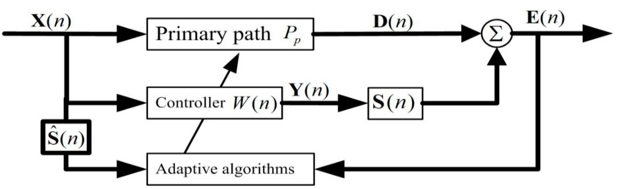
Figure 3.
The structure diagram of WPTDDM-FxLMS algorithm for the MIMO system.
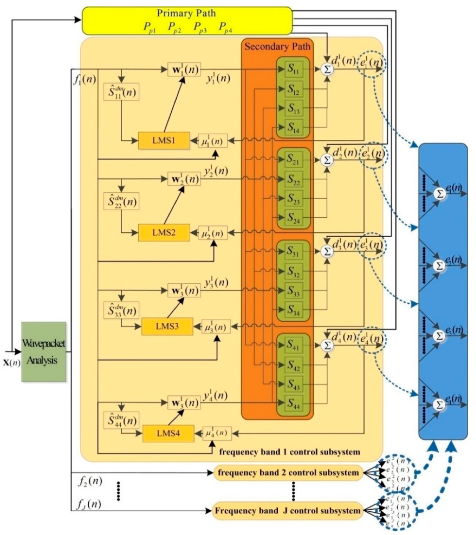
Figure 4.
(a) Haar wavelet tree termination node; (b) energy spectrum of Haar wavelet decomposition.
Figure 4.
(a) Haar wavelet tree termination node; (b) energy spectrum of Haar wavelet decomposition.
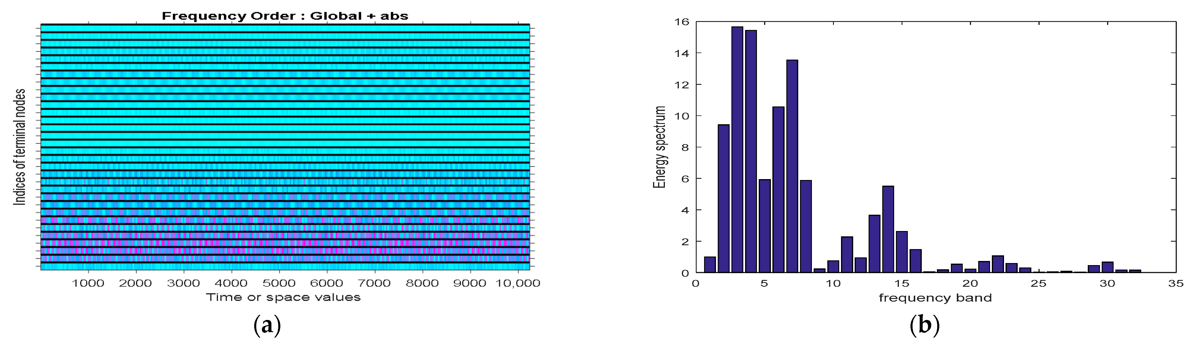
Figure 5.
(a) db5 wavelet tree termination node; (b) energy spectrum of db5 wavelet decomposition.

Figure 6.
(a) sym20 wavelet tree termination node; (b) energy spectrum of sym20 wavelet decomposition.
Figure 6.
(a) sym20 wavelet tree termination node; (b) energy spectrum of sym20 wavelet decomposition.
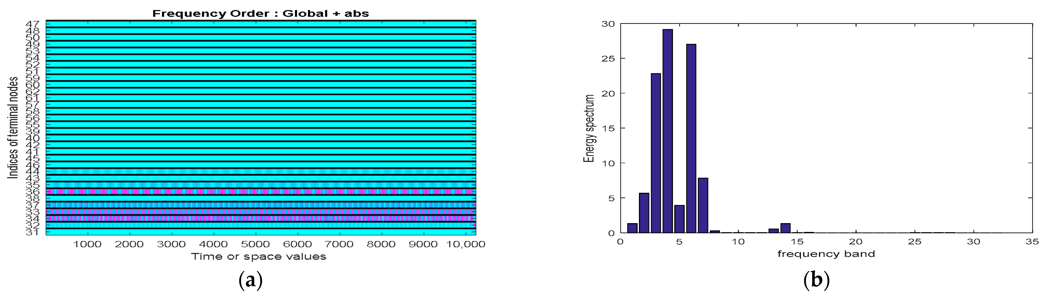
Figure 7.
(a) bior3.3 wavelet tree termination node; (b) energy spectrum of bior3.3 wavelet decomposition.
Figure 7.
(a) bior3.3 wavelet tree termination node; (b) energy spectrum of bior3.3 wavelet decomposition.
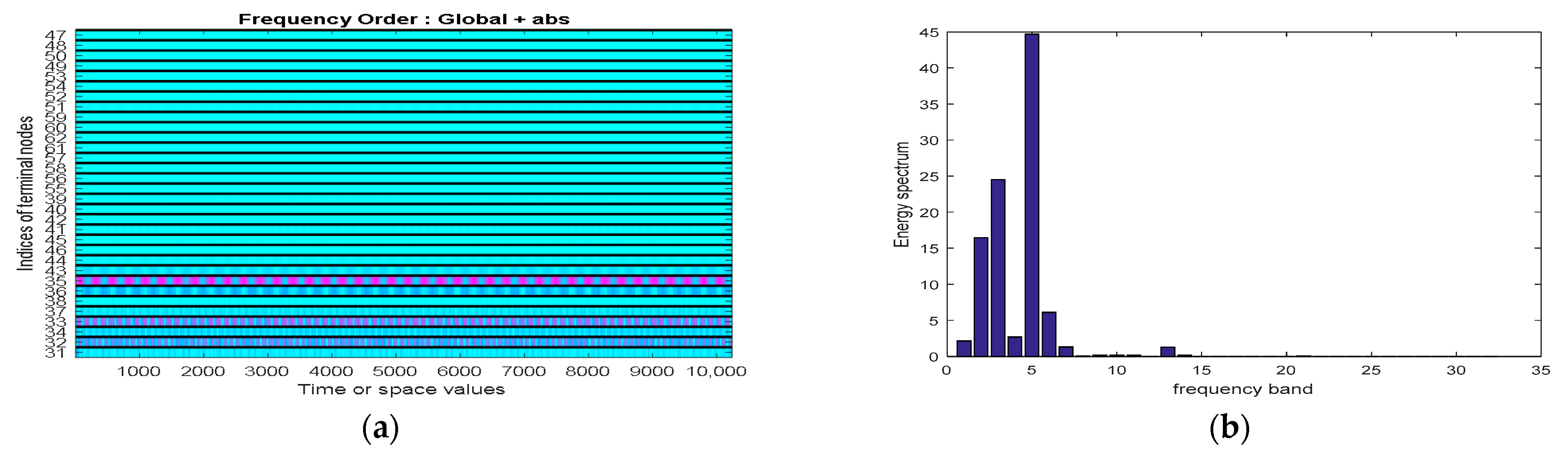
Figure 8.
Identification process in primary paths. (a) Identification of ; (b) identification of ; (c) identification of ; (d) identification of .
Figure 8.
Identification process in primary paths. (a) Identification of ; (b) identification of ; (c) identification of ; (d) identification of .
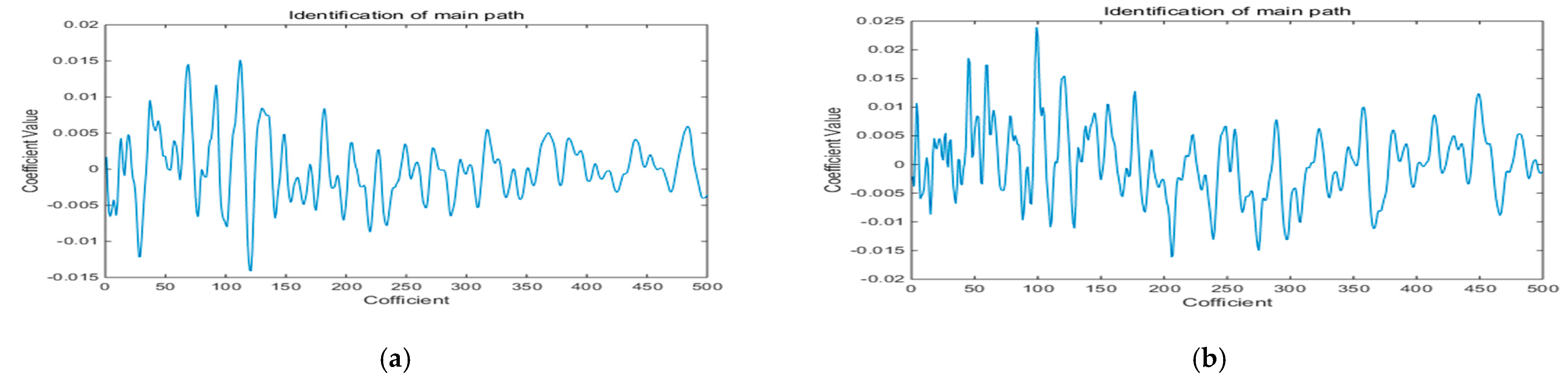
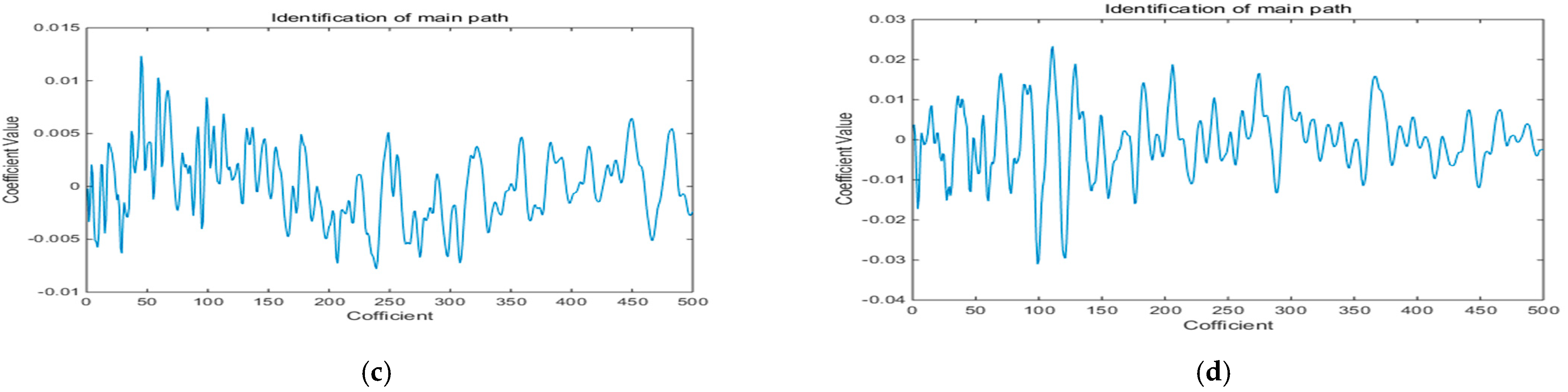
Figure 9.
Identification results in secondary paths. (a) Identification of ; (b) identification of ; (c) identification of ; (d) identification of ; (e) identification of ; (f) identification of ; (g) identification of ; (h) identification of ; (i) identification of ; (j) identification of ; (k) identification of ; (l) Identification of ; (m) identification of ; (n) identification of ; (o) identification of ; (p) identification of .
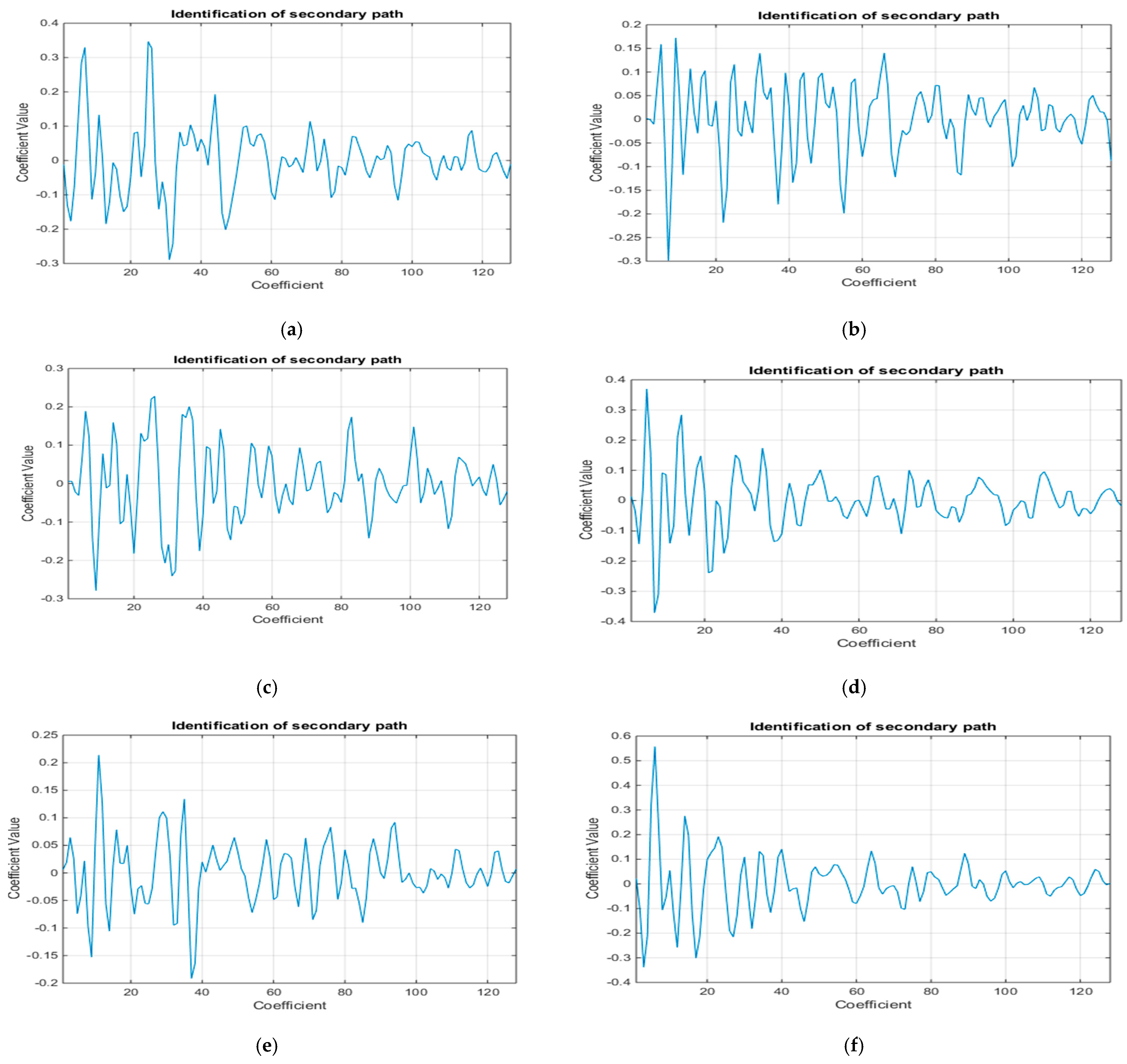
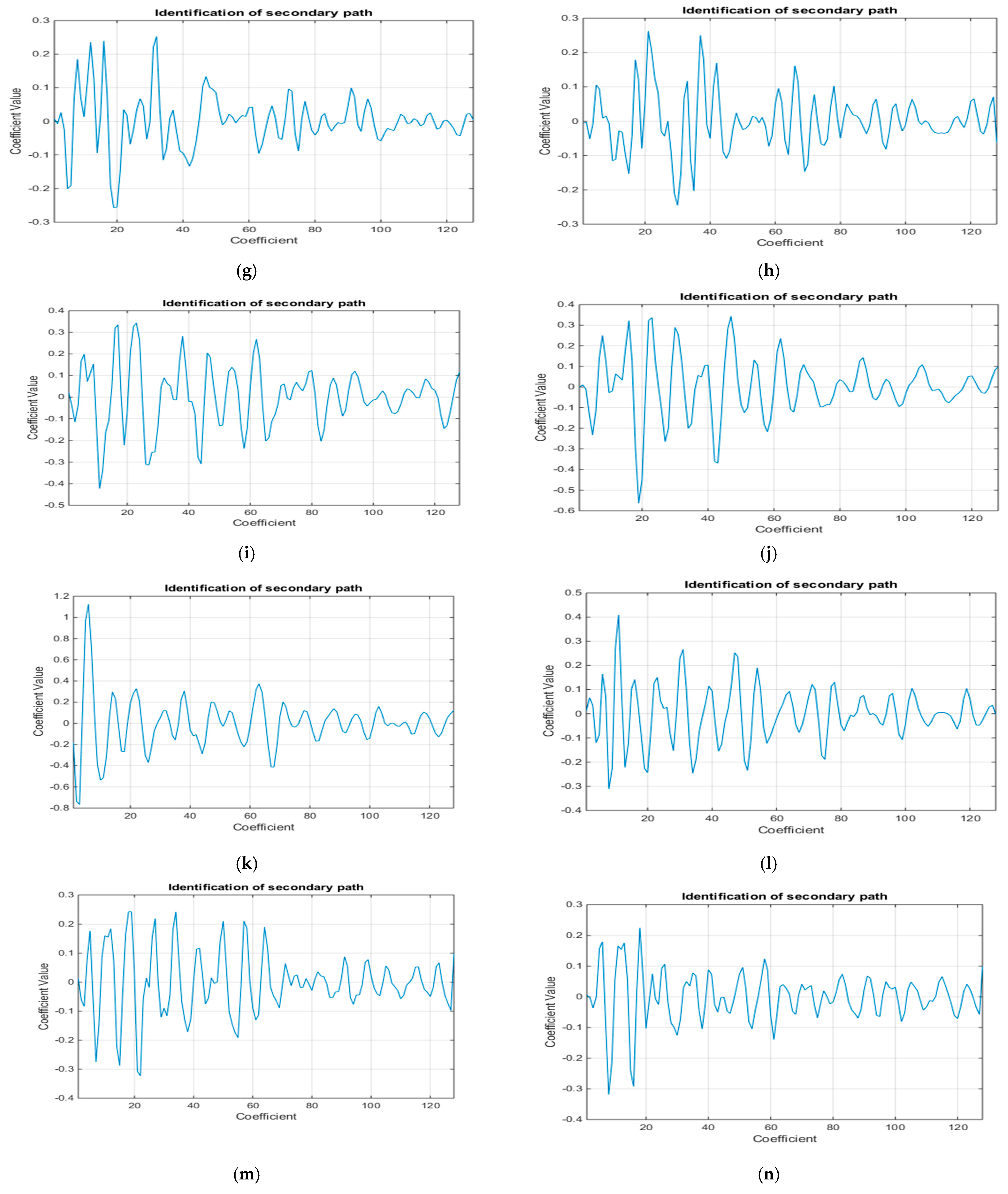

Figure 10.
(a) The time domain acceleration signal in measuring point 1#; (b) the acceleration signal spectrum in measuring point 1#.
Figure 10.
(a) The time domain acceleration signal in measuring point 1#; (b) the acceleration signal spectrum in measuring point 1#.
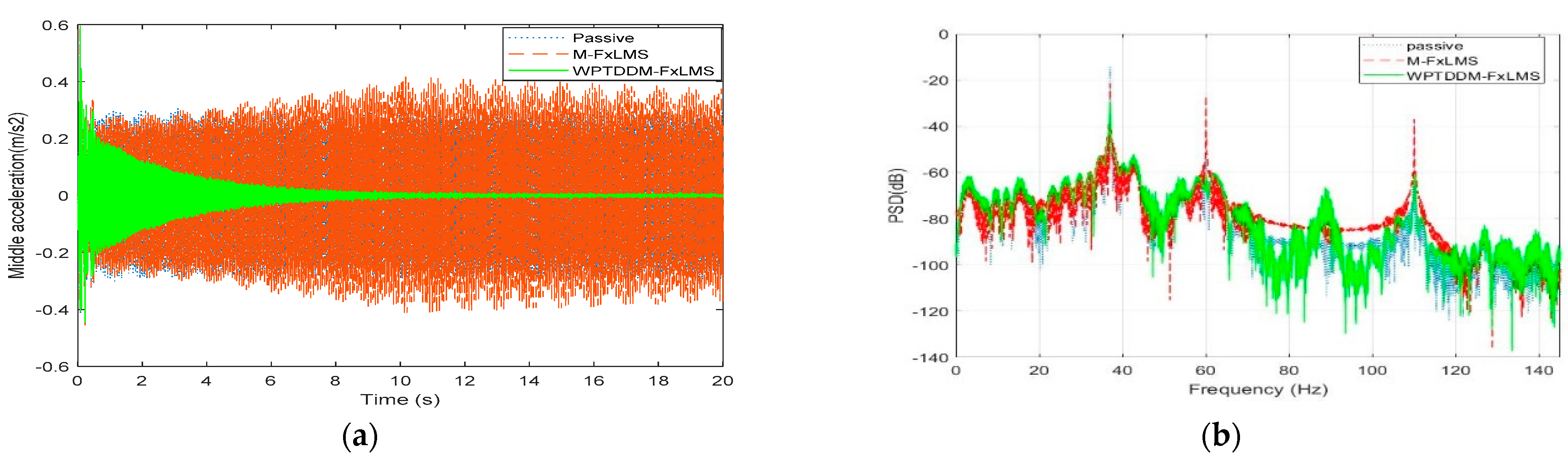
Figure 11.
(a) The time domain acceleration signal in measuring point 2#; (b) The acceleration signal spectrum in measuring point 2#.
Figure 11.
(a) The time domain acceleration signal in measuring point 2#; (b) The acceleration signal spectrum in measuring point 2#.

Figure 12.
(a) The time-domain acceleration signal in 3# measuring point 3#; (b) the acceleration signal spectrum in measuring point 3#.
Figure 12.
(a) The time-domain acceleration signal in 3# measuring point 3#; (b) the acceleration signal spectrum in measuring point 3#.
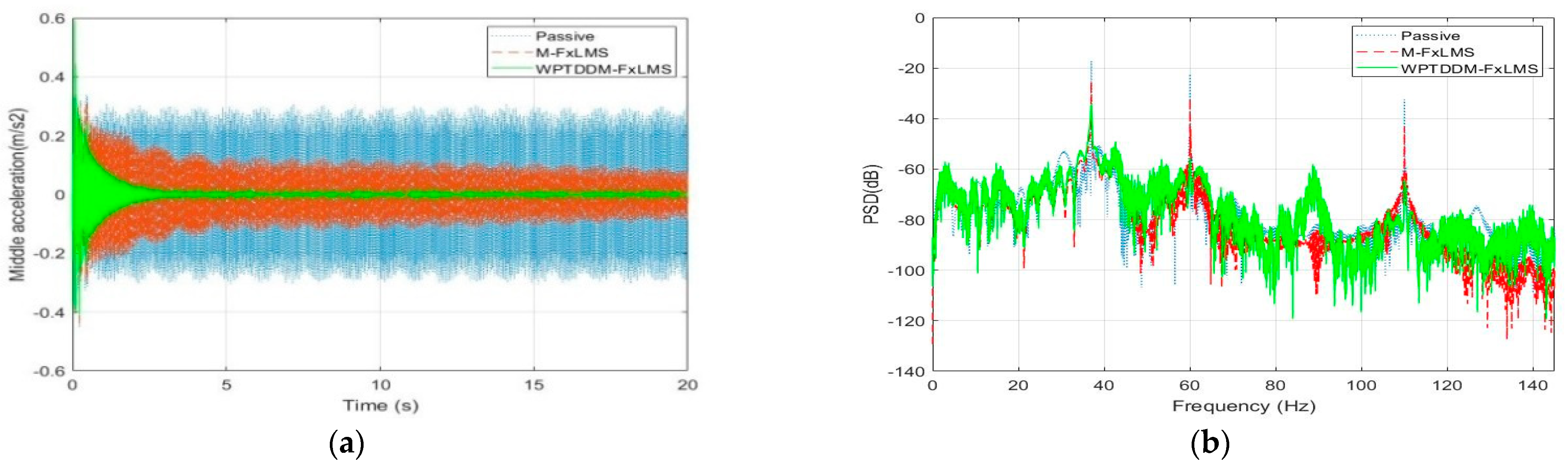
Figure 13.
(a) The time domain acceleration signal in measuring point 4#; (b) the acceleration signal spectrum in measuring point 4#.
Figure 13.
(a) The time domain acceleration signal in measuring point 4#; (b) the acceleration signal spectrum in measuring point 4#.

Figure 14.
Test rack and some equipment.
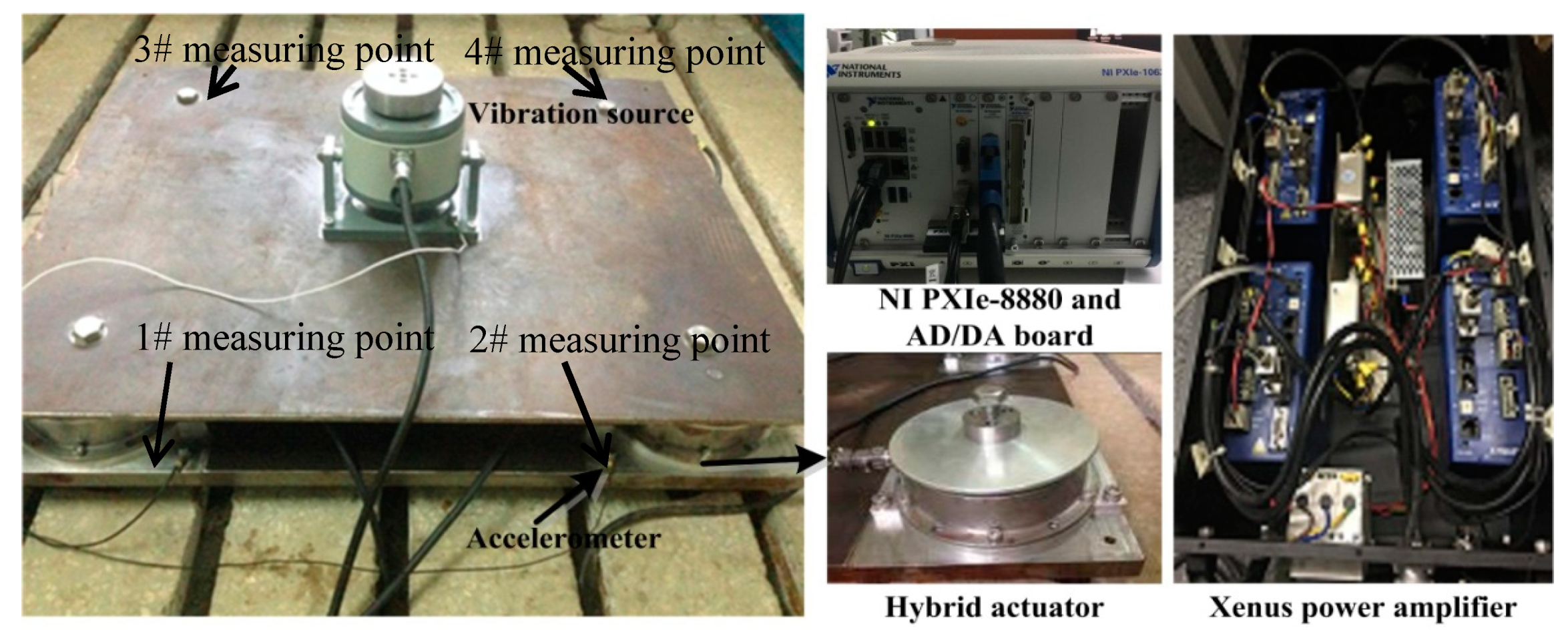
Figure 15.
Output force test for the active and passive integrated actuator.
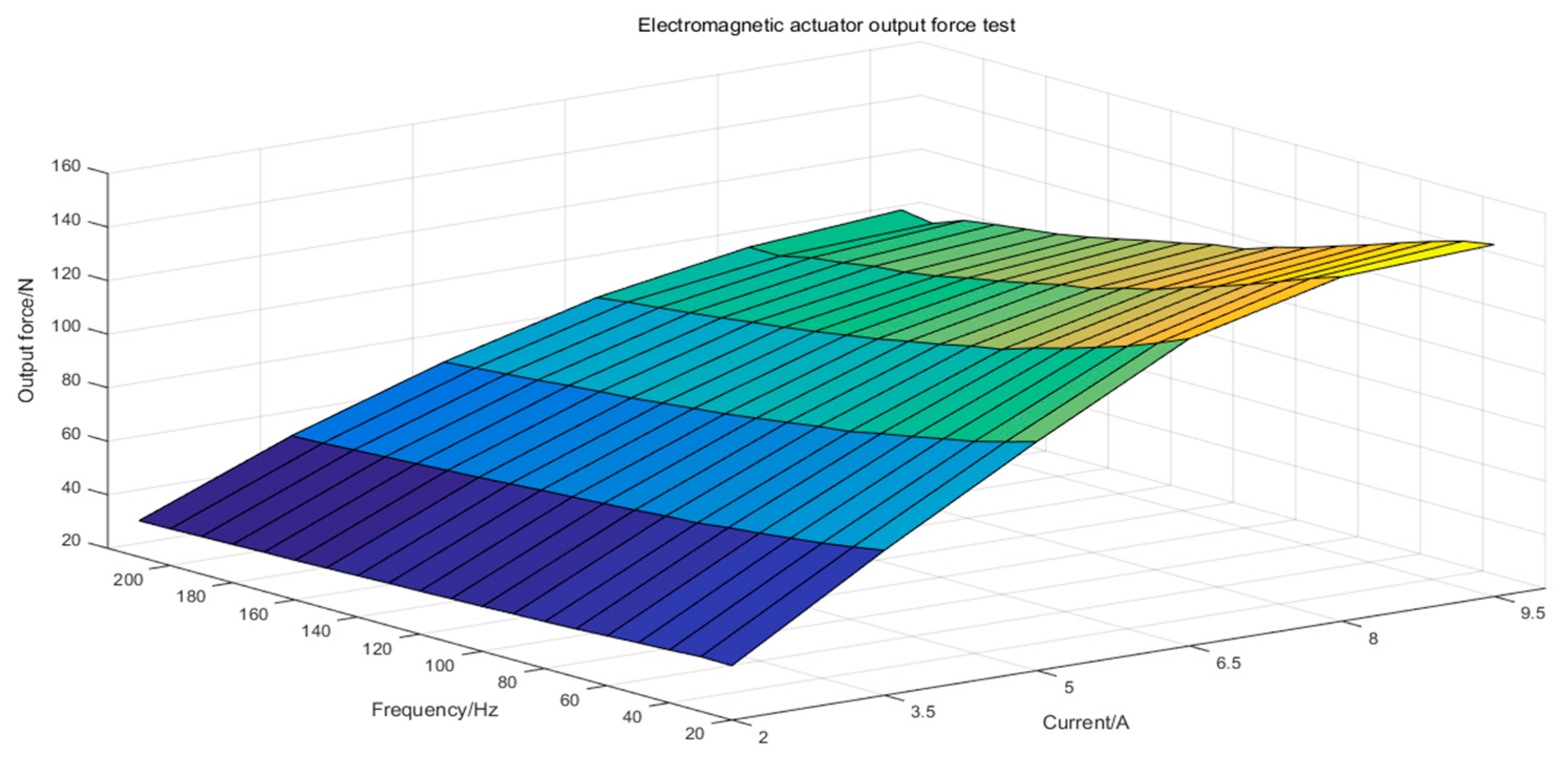
Figure 16.
(a) The time domain acceleration signal in measuring point 1#; (b) the acceleration signal spectrum in measuring point 1#.
Figure 16.
(a) The time domain acceleration signal in measuring point 1#; (b) the acceleration signal spectrum in measuring point 1#.
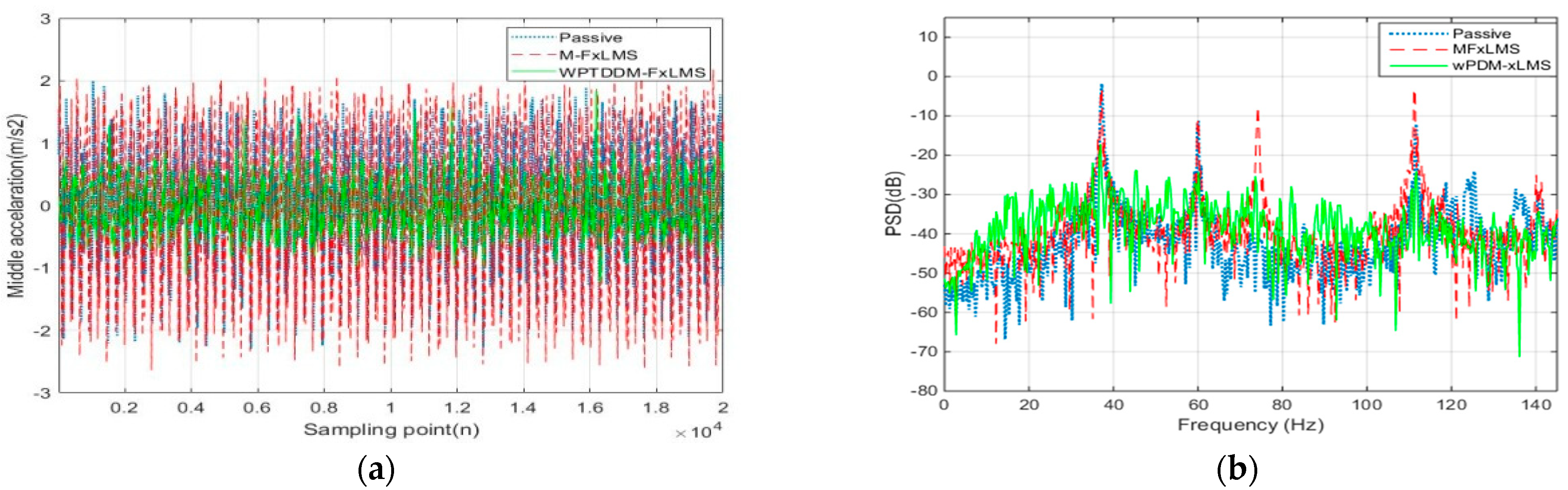
Figure 17.
(a) The time domain acceleration signal in measuring point 2#; (b) the acceleration signal spectrum in measuring point 2#.
Figure 17.
(a) The time domain acceleration signal in measuring point 2#; (b) the acceleration signal spectrum in measuring point 2#.

Figure 18.
(a) The time domain acceleration signal in measuring point 3#; (b) the acceleration signal spectrum in measuring point 3#.
Figure 18.
(a) The time domain acceleration signal in measuring point 3#; (b) the acceleration signal spectrum in measuring point 3#.
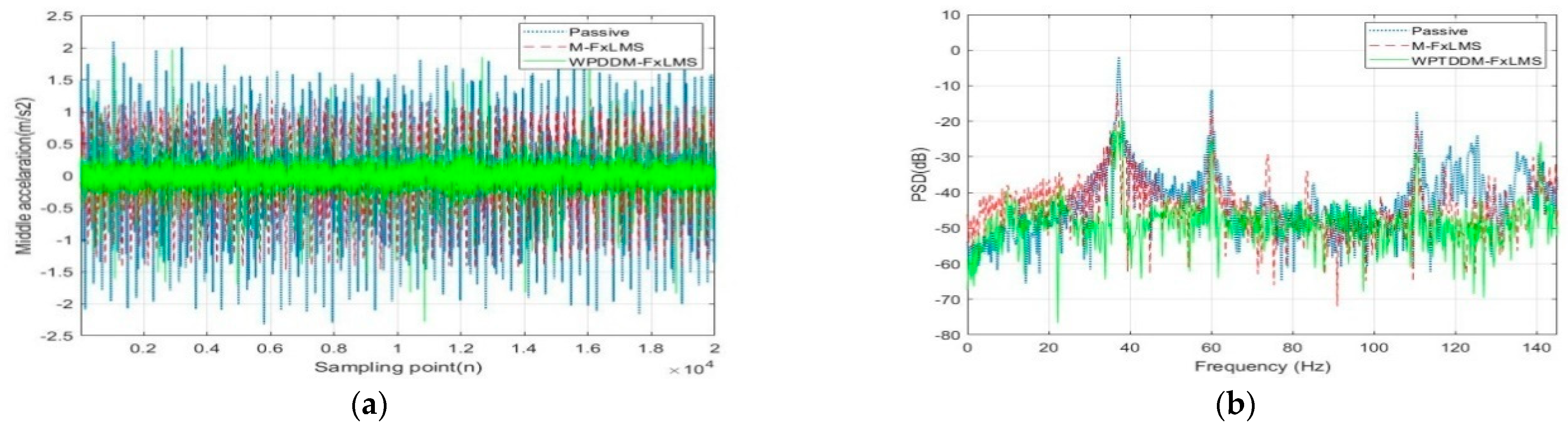
Figure 19.
(a) The time domain acceleration signal in measuring point 4#; (b) the acceleration signal spectrum in measuring point 4#.
Figure 19.
(a) The time domain acceleration signal in measuring point 4#; (b) the acceleration signal spectrum in measuring point 4#.
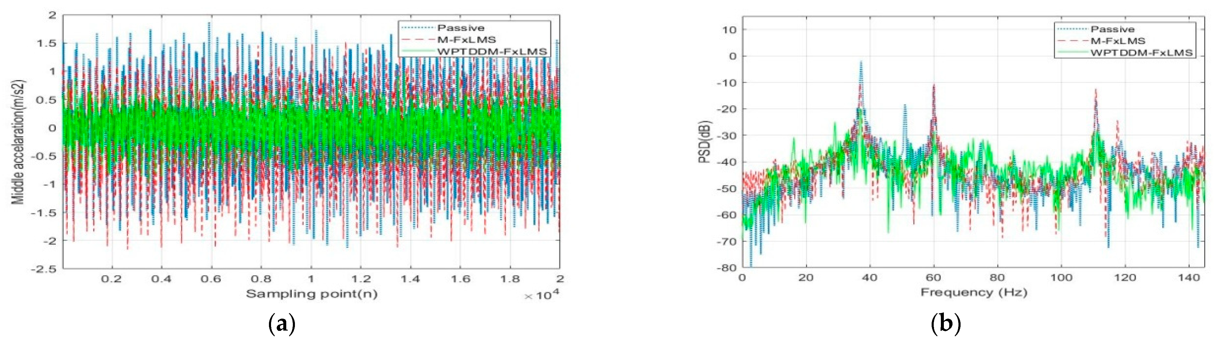
Figure 20.
The comparison of the theoretical simulation and experimental verification.

Table 1.
Simulation results with two algorithms.
| Error Signal 1# | Error Signal 2# | |||||
| (Hz) | Passive | M-FxLMS | WPTDDM-FxLMS | Passive | M-FxLMS | WPTDDM-FxLMS |
| 37 | −14.37 | −21.51 | −29.34 | −16.32 | −26.02 | −37.37 |
| 60 | −28.34 | −26.79 | −56.20 | −25.15 | −30.85 | −61.31 |
| 110 | −39.28 | −36.91 | −60.42 | −35.60 | −41.59 | −68.12 |
| Error Signal 3# | Error Signal 4# | |||||
| (Hz) | Passive | M-FxLMS | WPTDDM-FxLMS | Passive | M-FxLMS | WPTDDM-FxLMS |
| 37 | −17.18 | −24.32 | −34.14 | −17.44 | −27.05 | −34.42 |
| 60 | −22.41 | −31.17 | −55.99 | −26.59 | −28.06 | −46.86 |
| 110 | −32.90 | −43.63 | −62.42 | −37.47 | −40.52 | −57.86 |
Table 2.
Test control effect for two algorithms.
| Measuring Point 1# | Measuring Point 2# | |||||
| (Hz) | Passive | M-FxLMS | WPTDDM-FxLMS | Passive | M-FxLMS | WPTDDM-FxLMS |
| 37 | −1.82 | −3.38 | −17.2 | −2.18 | −5.94 | −19.59 |
| 60 | −11.12 | −11.80 | −24.25 | −11.35 | −14.21 | −27.59 |
| 110 | −12.05 | −3.36 | −24.13 | −14.26 | −29.32 | −28.92 |
| Measuring Point 3# | Measuring Point 4# | |||||
| (Hz) | Passive | M-FxLMS | WPTDDM-FxLMS | Passive | M-FxLMS | WPTDDM-FxLMS |
| 37 | −1.82 | −12.18 | −22.92 | −1.99 | −10.39 | −19.83 |
| 60 | −11.34 | −16.83 | −24.99 | −10.6 | −11.02 | −28.37 |
| 110 | −17.23 | −21.14 | −28.53 | −16.76 | −12.40 | −27.88 |
Publisher’s Note: MDPI stays neutral with regard to jurisdictional claims in published maps and institutional affiliations. |
© 2021 by the authors. Licensee MDPI, Basel, Switzerland. This article is an open access article distributed under the terms and conditions of the Creative Commons Attribution (CC BY) license (https://creativecommons.org/licenses/by/4.0/).
Share and Cite
MDPI and ACS Style
Yang, L.; Gao, W.; Yang, J.; Zhao, B.; Liu, L. A Novel Active Control Strategy with Decentralized Decoupling and Wavelet Packet Transformation: Design and Verification. Appl. Sci. 2021, 11, 3554. https://doi.org/10.3390/app11083554
AMA Style
Yang L, Gao W, Yang J, Zhao B, Liu L. A Novel Active Control Strategy with Decentralized Decoupling and Wavelet Packet Transformation: Design and Verification. Applied Sciences. 2021; 11(8):3554. https://doi.org/10.3390/app11083554
Chicago/Turabian StyleYang, Lihua, Weipeng Gao, Jun Yang, Bo Zhao, and Libin Liu. 2021. "A Novel Active Control Strategy with Decentralized Decoupling and Wavelet Packet Transformation: Design and Verification" Applied Sciences 11, no. 8: 3554. https://doi.org/10.3390/app11083554
Note that from the first issue of 2016, this journal uses article numbers instead of page numbers. See further details here.