
Wear of 17-4 PH Stainless Steel Patterned Surfaces Fabricated Using Selective Laser Melting


1
Department of Mechanical, Energy and Management Engineering, University of Calabria, Via P. Bucci, 87036 Rende, Italy
2
School of Mechanical and Design Engineering, University of Portsmouth, Anglesea Road, Anglesea Building, Portsmouth PO1 3DJ, UK
3
Department of Mechanical and Mechatronics Engineering, University of Waterloo, 200 University Avenue West, Waterloo, ON N2L 3G5, Canada
*
Author to whom correspondence should be addressed.
Appl. Sci. 2021, 11(19), 9317; https://doi.org/10.3390/app11199317
Submission received: 28 July 2021
/
Revised: 30 September 2021
/
Accepted: 4 October 2021
/
Published: 8 October 2021
(This article belongs to the Special Issue Tribological and Mechanical Properties Studies of Smart Materials at Micro–Nano Scale)
Abstract
:The recent developments in additive manufacturing (AM) are providing unprecedented opportunities in various fields, including the fabrication of advanced materials for tribological applications. The present work describes the results of an exploratory study focused on the analysis of 17-4 PH steel surfaces obtained using selective laser melting (SLM). In particular, the study includes the analysis of baseline (as-produced) and textured steel surfaces. Surface texturing comprises hexagonal prism structures (with or without dimples) arranged in a honeycomb pattern with 50 µm or 100 µm gap spacing. Starting from the minimum printing size enabled by the 3D printing platform, various textures are prepared by scaling up the characteristic dimensions of the prisms up to 500%. The obtained surface patterns are characterized (qualitatively and quantitatively) using a non-contact computerized numerical control (CNC) measuring system. The coefficient of friction (COF) was investigated using a Ball-on-Disk configuration using bearing steel balls as counterparts. For a fixed sliding speed, different contact loads and sliding radii were considered, while the tests were carried out in either dry or lubricant-impregnated conditions. The results of wear tests in both dry and lubricated conditions indicated that the baseline samples are provided with lower COF compared to the textured ones. For the latter, neither the gap spacing nor the presence of dimples led to significant variations in the COF. However, in lubricated conditions, the values of the COF for baseline and textured surfaces were closer and much smaller. In particular, the results provide clear indications regarding reducing the gap between prisms, which had a beneficial effect on the COF in lubricated conditions. Similarly, sensitivity to dimples was quite remarkable, with a reduction in the COF of about 30% when the larger gap spacing between the prisms was used.
1. Introduction
Friction and wear reduction are among the most critical pursuits in engineering since almost one-fifth of all energy produced worldwide is annually used to overcome friction [1]. Recent studies have focused on functional surfaces featuring bio-inspired superficial patterns or textures obtained using various technologies, including laser micro-machining or coining [2,3,4]. In particular, Volchok et al. [2] explored the possibility of introducing a regular surface microporosity in a tribo-pair to reduce fretting fatigue. It was found that the micropores can trap wear debris, removing it from the contact zone, thereby leading to an +88% increase in fatigue life with respect to the baseline value. It was observed that the depth of micropores may be unimportant once it exceeds a characteristic value related to wear debris size. Later on, Koszela et al. [3] studied the influence of dimples in lubricated conditions. The dimples were introduced to trap wear debris and lubricant and increase the load-carrying capacity. An influence of the running-in phase on the steady wear phase was observed, as well as a proportionality between the coefficient of friction and wear, under the conditions tested. It was found that, within a given range of dimple area density (i.e., the ratio between total dimple area and total surface area), the linear wear of the tested assembly could be reduced by about 27%, or else the effect of dimples was negative because of an increase in unit pressure. Rashwan [4] provided analytical proof, supported through experiments, about the existence of a minimum coefficient of friction (COF) related to the real area of contact under dry sliding. These studies are mainly focused on the tribological behaviour of negative surface textures (dimples); however, comprehensive investigations have been also performed on positive (protruding) surface textures [5]. As reported by Martini et al. [6], many body armours found in nature (e.g., those belonging to fish, snakes and armadillos) are created through the combination of finite size protruding elements whose arrangement allows significant enhancement of strength and toughness, often accompanied by reduced friction and wear.
Several manufacturing technologies are currently used for such complex surface structures, including micro-casting and 3D printing [7,8]. Additive manufacturing (AM) has been shown to be very promising and is currently being largely used to build customized products in a variety of industries, including automotive, aerospace and biomedical, implying a cost drop in the case of high-complexity parts [9]. One of the most popular AM technology for plastics and metals is represented by laser beam powder bed fusion (LB-PBF). Such technology allows us to build components with complex shapes by using a bottom-up approach, whereby mechanical parts are fabricated by melting and fusing either plastic or metallic powder layer by layer using a high-powered laser source.
Among the large set of AM materials that are currently available, the precipitation-hardening steel 17-4 PH (low carbon martensitic/austenitic steel) is making its way in a variety of applications because of its interesting mechanical properties, including high fracture toughness, fatigue strength and corrosion resistance [10,11,12]. Despite the growing interest, there is still a paucity of contributions focused on the tribological behaviour of LB-PBF 17-4 PH steel [13], of which wear resistance in conventionally manufactured conditions has been assessed in the past [14]. The present work aims to fill this gap and investigate the tribological behaviour of 17-4 PH steel disks featuring either a baseline as-produced surface or an array of protruding hexagonal prisms arranged in a honeycomb pattern. The investigated process is selective laser melting (SLM), which belongs to the powder bed fusion technologies. Additionally, since surface dimples have been shown to provide additional benefits in terms of wear [15,16,17], we have also investigated textured surfaces comprising hexagonal prisms with surface dimples. Non-contact CNC measurements and optical microscopy were carried out for qualitative and quantitative analysis of the manufactured samples, and to support a meaningful choice of sample dimensions for subsequent tribological tests. In addition, wear tests in dry and lubricated conditions were executed to ascertain the evolution of the coefficient of friction (COF) and the wear rate as a function of surface texture. Viable applications span from tuning friction in metal-forming processes such as deep drawing [18,19] and performance improvement of bioimplants [20].
2. Materials and Methods
The design stage for functional surfaces was supported by Rhinoceros 3D computer-aided design software (Version 5.0, Robert McNeel & Associates, Seattle, WA, USA), using a parametric design plugin (Grasshopper). Additively manufactured metallic parts were produced through selective laser melting technology (SLM), which belongs to the family of laser powder bed fusion processes. The ProX DMP 300 manufacturing system was used throughout this study (3D Systems Company, Rock Hill, SC, USA). The main characteristics of the manufacturing system and printing conditions are reported in Table 1.
Martensitic precipitation-hardening stainless steel powder (17-4 PH SS) has been used, whose composition is reported in Table 2.
Preliminary investigations have been performed to (i) assess the printing system capabilities and deviation from theoretical specifications in manufacturing the desired structures, and (ii) select suitable processing parameters for the textured surfaces. Different kinds of hexagonal structures (Figure 1) have been printed: (i) hexagonal prismatic features, and (ii) hexagonal prismatic features with cylindrical dimples, having a depth equal to the prism half-height (h = H/2). Each structure has been modelled according to the theoretical minimum feature dimensions allowed by the 3D printer hardware along the x- and y- directions, which are reported in Table 1. Samples having a disk-shaped base with a diameter of 50 mm and thickness of 5 mm were printed directly on the build plate of the machine and the pattern was printed concurrently, on top of the base.
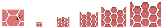
The manufactured textures were scaled up to 500% with respect to the starting theoretical minimum size allowed by the 3D printer. The schematics provided in Table 3 show, as an example, the scaled-up Hex structures. Notice that the minimum feature height considered was 200 µm, corresponding to Scale 1, as 5 times the theoretical layer thickness was found to be a viable starting dimension.
In order to perform qualitative and quantitative analysis of the obtained samples, a non-contact computerized numerical control (CNC) measuring system was employed (Quick Vision Apex-QVA by Mitutoyo Corporation, Kawasaki, Japan). The deviations between nominal and actual dimensions, as well as the circularity of cylindrical dimples, were determined using a proprietary software (QVPAK by Mitutoyo Corporation, Kawasaki, Japan). The circularity (roundness) was calculated as the width of the area defined by two concentric circles that bound the data points [21]. It is noted that cylindrical dimples were measured focusing on the bottom surface of the dimples.
Wear tests were carried out, under dry and lubricant-impregnated conditions. A Ball-on-Disk tribometer DTRB 70090 (CSM Instruments, Peseux, Switzerland) was employed in a standard laboratory environment, using single-way rotary mode and 6 mm-diameter 100Cr6 (AISI 52100) steel ball counterparts. The sample size was such that it was possible to carry out repeated tests on the same sample by changing the sliding radius. Testing procedure and parameters have been established based on the literature [22,23,24] and are summarized in Table 4.
The resulting curves were filtered by means of the tribometer proprietary software employing a moving average filter, while the coefficient of friction (COF) was calculated as follows:
Mass loss following wear tests was estimated using a gravimetrical method, i.e., weighing samples before and after each test using a balance with a sensitivity of 0.01 mg (Model CPA225D, Sartorius, Göttingen, Germany) [25]. Specific wear rate (SWR) was estimated according to [25] using the following equation:
Lubricant-impregnated tests were performed by applying 90 mm3 of 80/90 synthetic gear lubricant oil by means of a syringe at the disk-sample contact area, a few seconds before starting the test. Samples were cleaned before and after each test, using compressed air and an ultrasonic cleaner, employing absolute ethanol as the agent. All tests were carried out in the as-built/as-received conditions (Ra = 10 µm) to explore the corresponding performance absent post-processing steps, that could increase manufacturing cost and time. Two repetitions for each sample type and loading conditions were carried out, including baseline additively manufactured disks (B) with no pattern. Finally, the nomenclature employed to describe the results of tribological tests is explained in Table 5.
3. Results and Discussion
3.1. Analysis of Manufacuring Imperfections
Non-contact CNC measurements were carried out for qualitative analysis of the manufactured samples and to support a meaningful choice of sample dimensions for subsequent tribological tests. However, preliminary optical microscopy observations were made to discuss the most relevant outcomes of the manufacturing process and associated imperfections. Scale 1 and 5 samples (with and w/o dimples) are compared in Figure 2 to highlight deviations between nominal and as-produced surface structures.
The texture of Scale 1 samples did not display the expected prismatic shape and the dimples were quite uneven; because of these dimensional inaccuracies, these samples were excluded from the subsequent quantitative analyses. On the other hand, Scale 5 samples had a more refined shape and no major defects were observed, thereby suggesting satisfactory quality. At the intermediate scales, some degree of chamfering of the superficial edges and convex-shaped top surfaces were observed (see Figure 3).
Figure 4 provides an overview of the results obtained through CNC measurements. The nominal dimension of each feature is reported on the x-axis, while the y-axis shows the mean deviation between the actual and nominal dimensions. The error bars represent the half-standard deviation of each group of measurements. Notice that the standard deviation of repeated measurements was found to be at most around 10% of the mean value. Scale 1 samples have been omitted from the analysis for the reasons outlined earlier.
The data in Figure 4a indicate that the mean value of L is always below the nominal input value. In contrast, the gap d between adjacent prisms and the dimple size D could exceed or be smaller than the nominal dimensions. The variations concerning L and D measurements always remained below 10% with respect to the nominal dimensions. In comparison, deviations on d were larger than 10% on Scale 2, while dimple circularity deviated by about 15% and 28% on Scales 2 and 3, respectively. The overall results highlighted a tendency to obtain dimensions smaller than the nominal ones which may be due also to the effect of shrinkage [26,27]. A previous study indicates that the build direction affects shrinkage, dimensional deviations and part accuracy [28]. As a consequence, the results of the above measurements may not apply to surface textures obtained using different printing directions. Concerning the measurement procedure itself, it should be noted that the reflecting nature of the material used, as well as the chamfered/irregular edges of printed features, may have affected the results. Therefore, additional dispersion could have been introduced in the experimental data and a difficult-to-estimate bias is likely to be present. These issues showed up for all magnifications of the base structure.
3.2. Tribological Tests
Following the assessment of the manufacturing system capabilities, three different sets of disk-shaped plates have been prepared for subsequent tribological tests: (i) plates with no pattern (baseline-B), (ii) plates with Hex pattern and (iii) plates with Hex-D pattern. The first configuration enables an assessment of the tribological behaviour of as-printed steel. Concerning the selection of manufacturing parameters for the textured samples, it was based on the results reported in the previous section and with the aim to obtain sufficiently refined surface textures. The parameters were chosen from Scales 2, 3 and 4. In particular, Scale 2 was chosen for the size of dimples (D), Scale 3 for the prism size (L) and Scale 4 for the height (H). While the above dimensions (D, L, H) were set as constant in all tests, we decided to assess two distinct values of the gap between consecutive prisms, i.e., d = 50 µm and 100 µm, respectively. Notice that the work by Holovenko et al. [29], which focused on patterned stainless steel obtained using selective laser melting (SLM), showed that the surface structures need not to trap the wear debris in order to ensure proper lubrication. This aspect is strictly related to the size of the gaps with respect to debris size. The overall set of samples analysed in tribological tests is thus schematically provided in Figure 5, along with the corresponding nomenclature.
3.2.1. Unlubricated Testing Conditions
The results of dry tests are reported in Figure 6 and reveal the occurrence of different stages for the coefficient of friction (COF). In the case of baseline disks (B), the COF has an initial increasing trend (I) before dropping down to about 30% (II), and achieve an almost constant value (III). One possible explanation for the drop in the COF could be the severe wear of the baseline material.
Patterned samples show similar tribological behaviour: the running-in stage (I) had a distinctive trait in which the coefficient of friction rises to a certain value and falls quickly (reasonably related to degradation of surface pattern and the smoothening effect of material asperities); then, it rises again (II) and reaches a higher steady-state (III) value compared to the baseline sample (B).
In all circumstances, it is not straightforward to identify the number of laps at which steady-state conditions are achieved for the patterned samples, mainly because of the rapid evolution of the contact surface. However, it appears that starting from 4000 laps, there are no significant changes in the COF and, for this reason, the range of the data reported in Figure 6 is bounded at 7000 laps. It is worth noting that the COF does not show large “spikes”, which otherwise might have been indicative of significant plastic deformations.
It should be noted that the baseline samples reach an initial higher coefficient of friction with respect to Hex and Hex-D type samples, with values up to 0.95, while for patterned samples it stands between 0.68 and 0.86; however, following pattern degradation, a slight increase in COF was observed (II-III); in fact, the lowest value for the steady-state coefficient of friction was observed in R10_N5 tests on B samples and it was equal to 0.61, while the highest value was reached during R10_N5 tests on Hex-D_100, i.e., 0.91. The results suggest that there is no obvious trend related to the dimension of gaps or to the presence of dimples for both R10_N5 and R5_N2 dry tests. The main difference between various patterned samples is only given by the horizontal and vertical shifting of COF curves. The increase in the COF that occurred earlier in patterned samples with a larger gap distance between the prisms (i.e., 100 μm) might be due to the adverse evolution of the contact area. To gain more insights on this point, an assessment of the worn surfaces was carried out.
Figure 7 shows optical microscopy images of the wear tracks after R10_N5 tests, before and after sample cleaning. It can be noticed that wear debris escaped from completely filled gaps invading surrounding areas and, in a smaller amount, the sliding path. As can be observed in Figure 7, the wear track in the case of baseline samples is shallower and narrower with respect to that on patterned samples, and laser scanning tracks from 3D printing process are still discernible, as indicated by the arrows. The worn surface of samples displays the tearing of pattern features and furrows parallel to the sliding direction. Mechanisms of severe adhesive wear can be assumed for these dry test conditions [13], but the presence of other wear modes can be envisaged, combining abrasive, thermal and oxidative wear [30].
Modelling and experimental efforts have shown that the actual area of contact between the mating pair has a central role in influencing frictional contributions associated with adhesion and mechanical deformation, which can be eventually brought down to a minimum value [4]. However, the results reported herein indicate that after the initial running-in stage, at which a reduced COF was observed, the 3D-printed textured surfaces were likely affected by the rapid evolution of contact conditions. When the counterpart slides from one prismatic feature to another, it likely generates repeated collisions, worsening the tribological behaviour of the material pair. Such a dynamic contact condition could promote some form of fretting wear during tests that is absent in the baseline samples. Previous works have shown that the formation of surface irregularities following repeated contact may magnify the contact stress and increase the wear rate of the material [31], and that the effect depends also on the patterning technique used [6,32]. The wear debris collected after tests was analysed and is presented in Figure 8. These particles are irregularly shaped with a size ranging from tens to hundreds of microns, as further proof of the involvement of severe wear mechanisms [33].
Concerning the counterparts, wear tracks are reported in Figure 9. The tracks are larger in the case of tests on baseline samples compared to the case of Hex and Hex-D disks, implying a lower amount of material loss, and traces of plastic deformation are recognizable. It is possible to observe that while the surface of samples shows the presence of some embedded particles, the same does not happen for the counterparts.
Using data from weighing, specific wear rates were estimated and are reported in Figure 10. Under these testing conditions, the hexagonal pattern does not reduce the rate of wear but, before the debris completely filled the gap between the prismatic features and the pattern deteriorated, the coefficient of friction was found to be smaller than the baseline sample.
3.2.2. Lubricated Testing Conditions
The results of lubricated tests are shown in Figure 11. In this case, the running-in stage is hardly distinguishable, but should be located below 50 laps. All curves are characterized by a slightly decreasing COF. The lowest value, measured in R13.5_N5_L tests on B samples, is equal to 0.12, while the highest was achieved in R13.5_N5_L tests on Hex_100, and corresponds to about 0.23. Therefore, both the baseline and textured steel samples provide remarkably low COF, with smooth development similar to that reported in [13].
However, the results of lubricated tests provide a clear indication regarding the effect of reducing the gap between prisms, which indeed has a beneficial effect on the COF. Similarly, the dimples (Hex-D) enabled a further reduction. It is also worth noting that the sensitivity to the presence of dimples is quite remarkable for larger spacing (gaps) between the prisms. A reduction of about 30% was observed when dimples were included in the samples with a gap of about 100 µm. However, for the remaining samples (gap 50 µm) the presence of dimples appears to be less significant and may not be needed. Nevertheless, the combination of those effects is not enough to ensure the better tribological behaviour of patterned samples with respect to unpatterned ones. Considering tribological system features, liable influencing factors on tribo-pair behaviour can be found in the amount of real contact area and a geometric effect related to actual shape of the 3D-printed features. It has been recognized [4] that the real area of contact has a central role in influencing friction force components related to adhesion and mechanical deformation. In addition, it has been analytically and experimentally demonstrated that friction force, in dry contact conditions, can reach a minimum value as a function of these factors; a similar occurrence was observed in lubricated conditions [3]. It stands to reason that in this case, area of contact, influenced by material properties and surface roughness and altered by the presence pattern, could have negatively affected contact conditions.
Furthermore, as shown in Figure 3b, the actual surface of prisms is not perfectly flat. While the depression in the central area of prisms (more pronounced in the case of type Hex-D samples) might guide the ball during its motion, thus providing a beneficial effect, the same might not happen when the counterpart slides from one prism to another, thus generating repeated collisions and worsening the tribological behaviour of the material pair (exemplified in Figure 12).
The manufacturing process might have also been responsible too in affecting the response of system under repeated collisions; it has been found, in other cases, that the wear behaviour of tested samples changes according to the patterning technique used [2,4]. It also needs to be borne in mind that lubricant contained in the interstices of the structure might exert a more or less marked influence on the total friction force, depending on the lubrication regime and flow behaviour [31] influenced by testing conditions, aspect ratio of channels and dimples and quantity of lubricant.
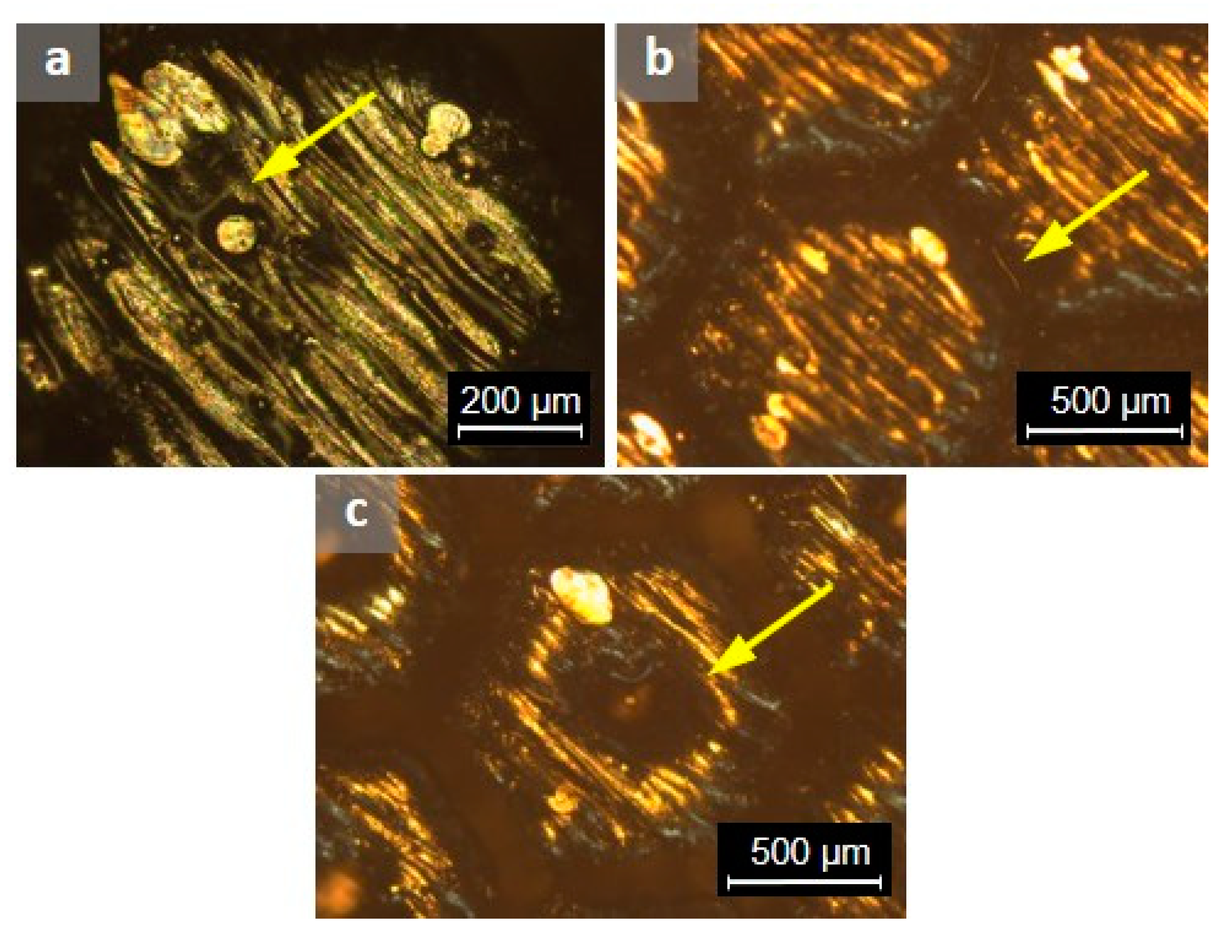
Friction and wear reduction with respect to the unlubricated test have been shown to be significant; for this reason, the wear track on the counterpart was not observed (Figure 13) and mild wear below the detection limit of the employed gravimetrical method. Traces of lubricant throughout samples are evident after tests, unevenly distributed. In particular, the lubricant became trapped in between laser scanning tracks, as shown in Figure 14a, on the bottom of gaps as illustrated in Figure 14b, as well as into the dimples highlighted in Figure 14c.
4. Conclusions
The present work assessed the wear behaviour of 3D-printed 17-4 PH stainless steel in unpatterned (baseline) and honeycomb-patterned configurations. Preliminary qualitative and quantitative investigations were performed to ascertain the deviations between printed structures and theoretical ones. The preliminary assessment investigated tribological behaviour in as-produced conditions through Ball-on-Disk tests employing different parameters and lubrication conditions. The dry tests indicated that the coefficient of friction (COF) of the baseline samples was initially larger than that of the textured surfaces before dropping by about 30% and reaching a steady state. Baseline steady-state COF was slightly lower than that analogous for the textured surface (0.6–0.7 compared to 0.8). In both cases, the obtained values were shown to be essentially independent of the testing parameters employed. Regarding lubricated tests, the running-in stage was hardly distinguishable, and a slightly decreasing COF characterized all curves. Both the baseline and textured steel samples are provided with low COF, but the lubricated tests have shown that reducing the gap between prisms has a beneficial effect. The lowest value of COF pertained to baseline samples (0.12), while the highest (0.23) was recorded on the textured samples with no dimples and the largest gap spacing, i.e., 100 µm. Similarly, it was shown that the introduction of dimples has a remarkable impact on COF, but only for larger spacing (gaps) between the prisms, with an observed reduction of about 30%. In fact, for smaller gaps (i.e., 50 µm), the presence of dimples appeared to be less significant. Future works could have a twofold objective. On the one hand, the development and calibration of finite element models that can support the design and manufacturing of the patterns would be helpful to identify suitable new configurations. On the other hand, a more comprehensive experimental study would be helpful to assess such designs. In any case, the results of this work undoubtedly represent a valid starting point toward the above objective.
Author Contributions
Conceptualization, methodology, validation, M.S., J.Z. and M.A.; software, formal analysis, investigation, data curation, writing—original draft preparation, visualization, M.S.; resources, supervision, project administration, writing—review and editing, J.Z. and M.A. All authors have read and agreed to the published version of the manuscript.
Funding
This research received no external funding.
Institutional Review Board Statement
Not applicable.
Informed Consent Statement
Not applicable.
Data Availability Statement
Not applicable.
Acknowledgments
M.S. acknowledges the support received from the University of Calabria (UNICAL) through the International Mobility Program MoST (2018–2019). This work was carried out in part using the facilities available at the MaTeRiA Laboratory at UNICAL. J.Z. acknowledges the support of a TRIF fellowship received from the University of Portsmouth.
Conflicts of Interest
The authors declare no conflict of interest.
References
- Holmberg, K.; Erdemir, A. Global impact of friction on energy consumption, economy and environment. FME Trans. 2015, 43, 181–185. [Google Scholar] [CrossRef]
- Volchok, A.; Halperin, G.; Etsion, I. The effect of surface regular microtopography on fretting fatigue life. Wear 2002, 253, 509–515. [Google Scholar] [CrossRef]
- Koszela, W.; Pawlus, P.; Galda, L. The effect of oil pockets size and distribution on wear in lubricated sliding. Wear 2007, 263, 1585–1592. [Google Scholar] [CrossRef]
- Rashwan, O. Micro Surface Texturing for Friction Control; University of Windsor: Windsor, ON, Canada, 2013. [Google Scholar]
- Abdel-aal, H.A. Surface Topography: Metrology and Properties Functional surfaces for tribological applications: Inspiration and design. Surf. Topogr. Metrol. Prop. 2016, 4, 043001. [Google Scholar] [CrossRef]
- Martini, R.; Balit, Y.; Barthelat, F. A comparative study of bio-inspired protective scales using 3D printing and mechanical testing. Acta Biomater. 2017, 55, 360–372. [Google Scholar] [CrossRef] [PubMed]
- Zhang, S.; Zeng, X.; Matthews, D.T.A.; Igartua, A.; Rodriguez-Vidal, E.; Contreras Fortes, J.; Saenz de Viteri, V.; Pagano, F.; Wadman, B.; Wiklund, E.D.; et al. Selection of micro-fabrication techniques on stainless steel sheet for skin friction. Friction 2016, 4, 89–104. [Google Scholar] [CrossRef] [Green Version]
- du Plessis, A.; Broeckhoven, C.; Yadroitsava, I.; Yadroitsev, I.; Hands, C.H.; Kunju, R.; Bhate, D. Beautiful and Functional: A Review of Biomimetic Design in Additive Manufacturing. Addit. Manuf. 2019, 27, 408–427. [Google Scholar] [CrossRef]
- Fera, M.; Macchiaroli, R.; Fruggiero, F.; Lambiase, A. A new perspective for production process analysis using additive manufacturing—complexity vs production volume. Int. J. Adv. Manuf. Technol. 2018, 95, 673–685. [Google Scholar] [CrossRef]
- Carneiro, L.; Jalalahmadi, B.; Ashtekar, A.; Jiang, Y. Cyclic deformation and fatigue behavior of additively manufactured 17–4 PH stainless steel. Int. J. Fatigue 2019, 123, 22–30. [Google Scholar] [CrossRef]
- Rotella, G.; Filice, L. Surface modifications induced by roller burnishing of Ti6Al4V under different cooling/lubrication conditions. In Selected Topics in Manufacturing; Springer: Cham, Switzerland, 2019; pp. 9–11. [Google Scholar]
- Lashgari, H.R.; Xue, Y.; Onggowarsito, C.; Kong, C.; Li, S. Microstructure, Tribological Properties and Corrosion Behaviour of Additively Manufactured 17-4PH Stainless Steel: Effects of Scanning Pattern, Build Orientation, and Single vs. Double scan. Mater. Today Commun. 2020, 25, 101535. [Google Scholar] [CrossRef]
- Kc, S.; Nezhadfar, P.D.; Phillips, C.; Kennedy, M.S.; Shamsaei, N.; Jackson, R.L. Tribological behavior of 17–4 PH stainless steel fabricated by traditional manufacturing and laser-based additive manufacturing methods. Wear 2019, 440–441, 203100. [Google Scholar] [CrossRef]
- Bressan, J.D.; Daros, D.P.; Sokolowski, A.; Mesquita, R.A.; Barbosa, C.A. Influence of hardness on the wear resistance of 17-4 PH stainless steel evaluated by the pin-on-disc testing. J. Mater. Process. Technol. 2008, 205, 353–359. [Google Scholar] [CrossRef]
- Tsipenyuk, A.; Varenberg, M. Use of biomimetic hexagonal surface texture in friction against lubricated skin. J. R. Soc. Interface 2014, 11, 20140113. [Google Scholar] [CrossRef] [PubMed]
- Huang, W.; Wang, X. Biomimetic design of elastomer surface pattern for friction control under wet conditions. Bioinspiration Biomim. 2013, 8, 046001. [Google Scholar] [CrossRef] [Green Version]
- Murarash, B.; Itovich, Y.; Varenberg, M. Tuning elastomer friction by hexagonal surface patterning. Soft Matter 2011, 7, 5553–5557. [Google Scholar] [CrossRef]
- Zabala, A.; Galdos, L.; Childs, C.; Llavori, I.; Aginagalde, A.; Mendiguren, J.; de Argandoña, E.S. The interaction between the sheet/tool surface texture and the friction/galling behaviour on aluminium deep drawing operations. Metals 2021, 11, 979. [Google Scholar] [CrossRef]
- Folle, L.F.; Schaeffer, L. Effect of surface roughness and lubrication on the friction coefficient in deep drawing processes of aluminum alloy aa1100 with fem analysis. Rev. Mater. 2019, 24. [Google Scholar] [CrossRef] [Green Version]
- Gang, S.; Fengzhou, F.; Chengwei, K. Tribological Performance of Bioimplants: A Comprehensive Review. Nanotechnol. Precis. Eng. 2018, 1, 107–122. [Google Scholar] [CrossRef]
- The American Society of Mechanical Engineers. Measurement Of Plain External Diameters For Use As Master Discs Or Cylindrical Plug Gages; B89.1.5-1998 (R2019); The American Society of Mechanical Engineers: New York, NY, USA, 2019. [Google Scholar]
- Qin, W.; Kang, J.; Li, J.; Yue, W.; Liu, Y.; She, D.; Mao, Q.; Li, Y. Tribological Behavior of the 316L Stainless Steel with Heterogeneous Lamella Structure. Materials 2018, 11, 1839. [Google Scholar] [CrossRef] [Green Version]
- Meng, J.; Loh, N.H.; Tay, B.Y.; Fu, G.; Tor, S.B. Tribological behavior of 316L stainless steel fabricated by micro powder injection molding. Wear 2010, 268, 1013–1019. [Google Scholar] [CrossRef]
- Duchosal, A.; Joly, D.; Leroy, R.; Serra, R. Effects of Microstructure of Compacted Graphite Iron in Tribological Strategy. J. Tribol. 2018, 140, 051302. [Google Scholar] [CrossRef]
- ASTM, G99. Standard Test Method for Wear Testing with a Pin-on-Disk Apparatus; ASTM Int.: West Conshohocken, PA, USA, 2016; Volume G99, pp. 1–5. [Google Scholar] [CrossRef]
- German, R.M. Powder Metallurgy Science, 2nd ed.; Metal Powder Industry: Princeton, NJ, USA, 1994. [Google Scholar]
- Paul, R.; Anand, S.; Gerner, F. Effect of Thermal Deformation on Part Errors in Metal Powder Based Additive Manufacturing Processes. J. Manuf. Sci. Eng. 2014, 136. [Google Scholar] [CrossRef]
- Senthilkumaran, K.; Pandey, P.M.; Rao, P.V.M. Influence of building strategies on the accuracy of parts in selective laser sintering. Mater. Des. 2009, 30, 2946–2954. [Google Scholar] [CrossRef]
- Holovenko, Y.; Antonov, M.; Kollo, L.; Hussainova, I. Friction studies of metal surfaces with various 3D printed patterns tested in dry sliding conditions. Proc. Inst. Mech. Eng. Part J J. Eng. Tribol. 2018, 232, 43–53. [Google Scholar] [CrossRef] [Green Version]
- Cinca, N.; Guilemany, J.M. Cold Gas Sprayed Stellite-6 Coatings and their Wear Resistance. J. Mater. Sci. Eng. 2013, 02. [Google Scholar] [CrossRef] [Green Version]
- Grützmacher, P.G.; Rosenkranz, A.; Szurdak, A.; Gachot, C.; Hirt, G.; Mücklich, F. Effects of Multi-Scale Patterning on the Run-In Behavior of Steel–Alumina Pairings under Lubricated Conditions. Adv. Eng. Mater. 2018, 20, 1–8. [Google Scholar] [CrossRef]
- Peter, J.B. Tribosystem Analysis: A Practical Approach to the Diagnosis of Wear Problems, 1st ed.; CRC Press, Taylor & Francis Group: Boca Raton, FL, USA, 2017. [Google Scholar] [CrossRef]
- Bhushan, B. Introduction to Tribology, 2nd ed.; John Wiley & Sons, Ltd.: Hoboken, NJ, USA, 2013. [Google Scholar]
Figure 1.
Different kinds of hexagonal prism tested for printing (z- is the build direction).
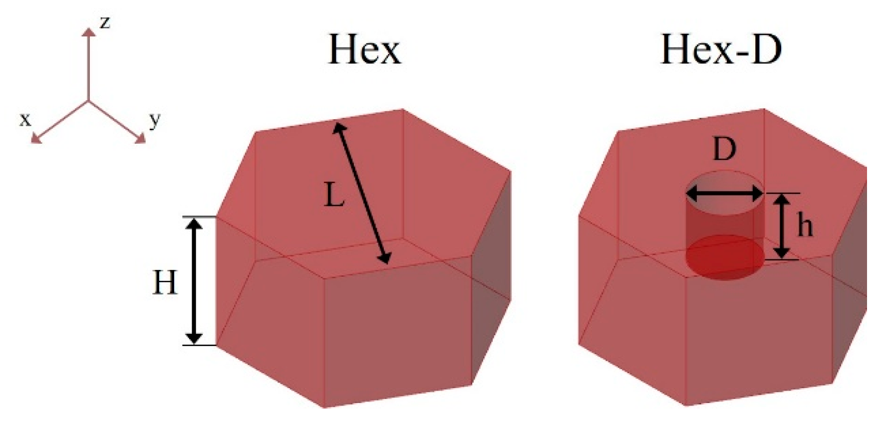
Figure 2.
Hex samples at (a) Scale 1 and (b) Scale 5; Hex-D samples at (c) Scale 1 and (d) Scale 5.

Figure 3.
Samples from Scale 3 (a) Hex, (b) Hex-D.
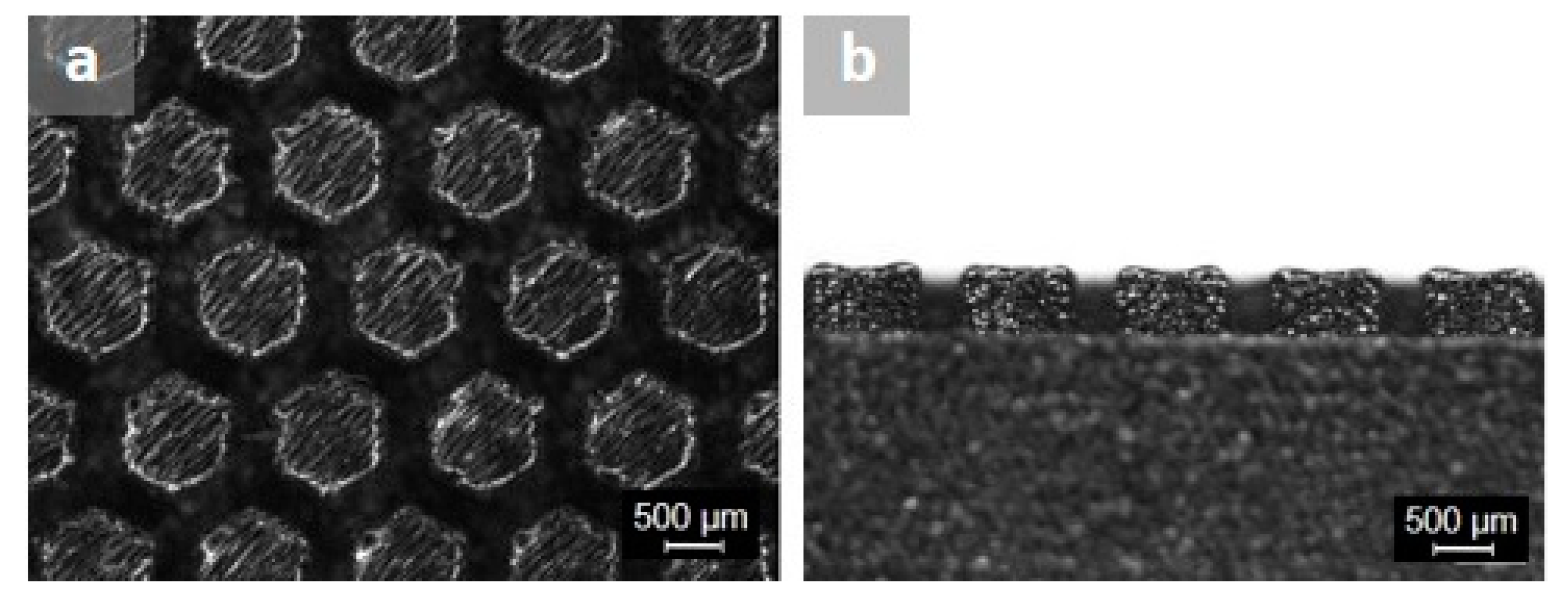
Figure 4.
Dimensional deviations in printed structures as obtained using a CNC measuring system related to (a) twice hexagon apothem L, (b) dimple diameter D, (c) gap d between adjacent prisms, (d) dimple circularity.
Figure 4.
Dimensional deviations in printed structures as obtained using a CNC measuring system related to (a) twice hexagon apothem L, (b) dimple diameter D, (c) gap d between adjacent prisms, (d) dimple circularity.
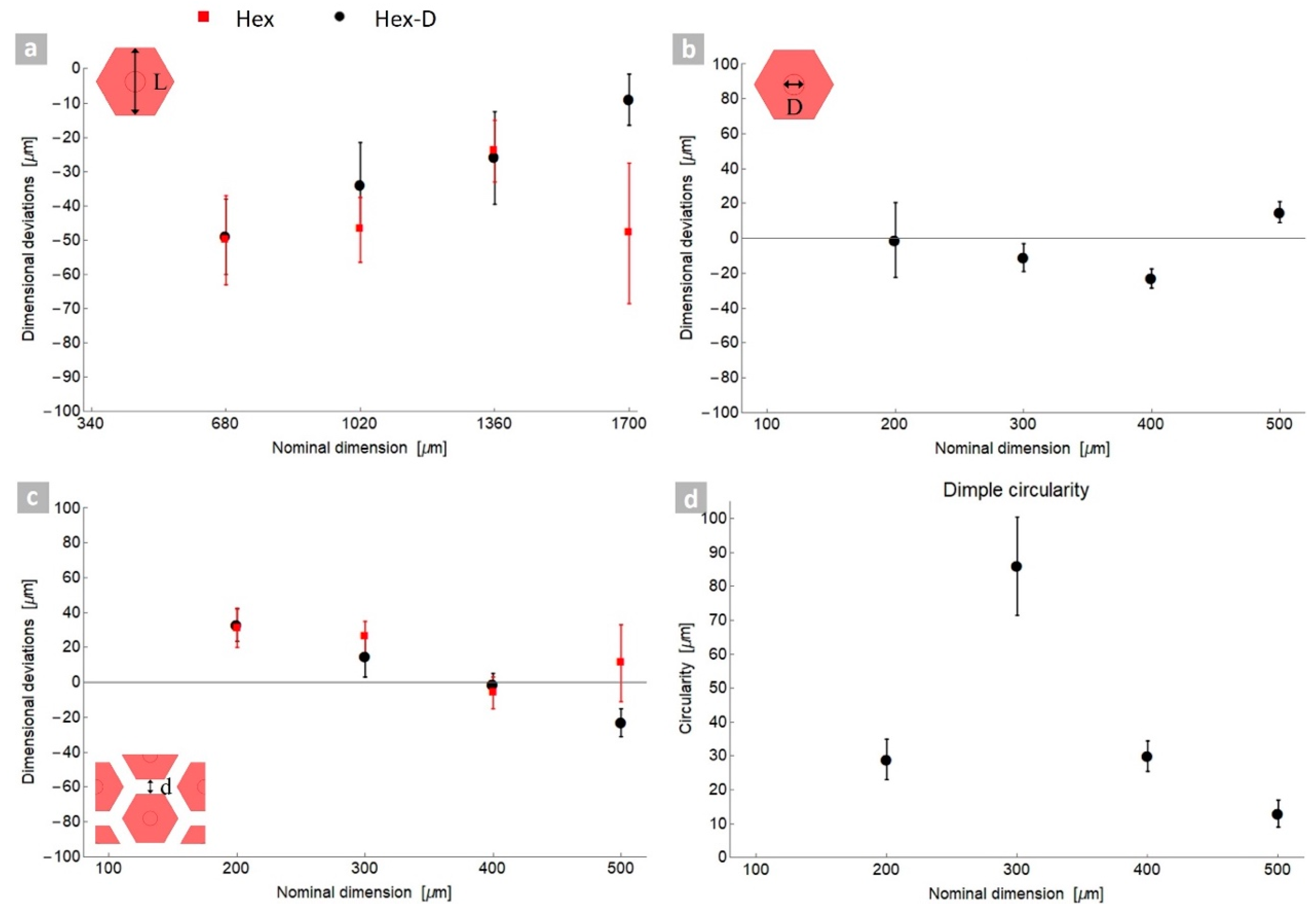
Figure 5.
Samples employed for tribological tests and ensuing nomenclature.
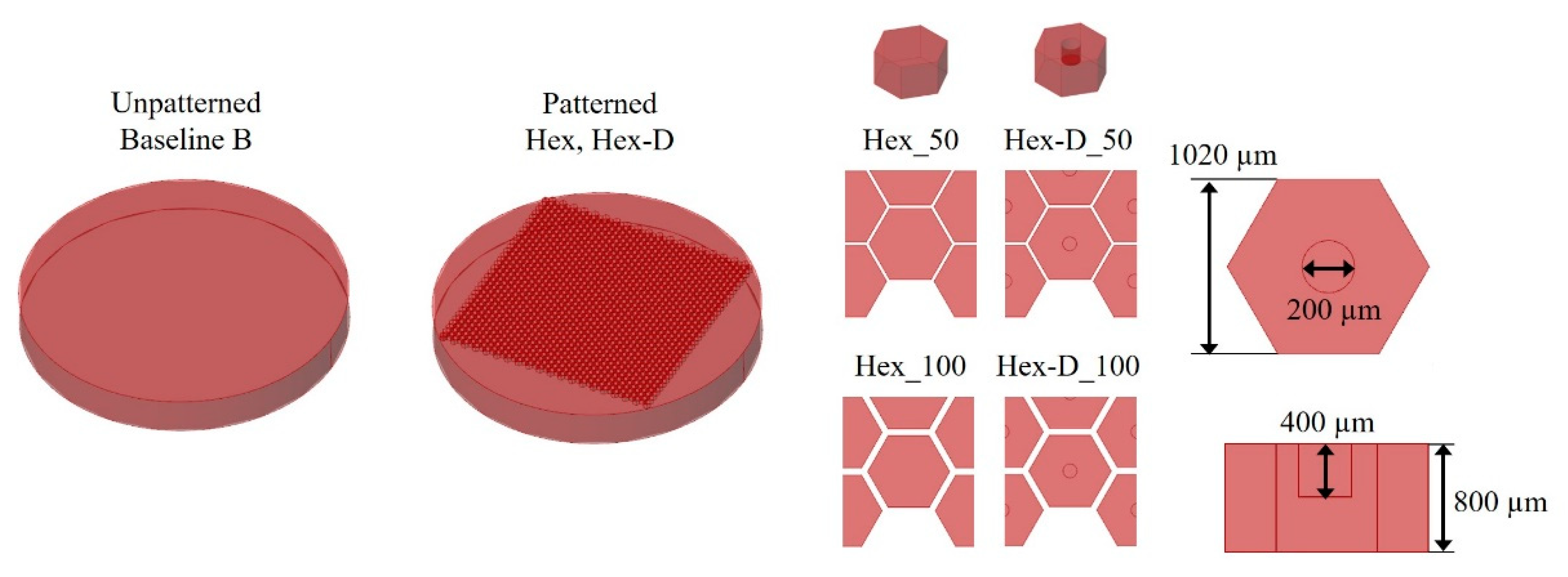
Figure 6.
Coefficient of friction (COF) for unlubricated tests and exemplification of friction stages; (a) sliding radius 10 mm, normal load 5 N (R10_N5), (b) sliding radius 5 mm, normal load 2 N (R5_N2).
Figure 6.
Coefficient of friction (COF) for unlubricated tests and exemplification of friction stages; (a) sliding radius 10 mm, normal load 5 N (R10_N5), (b) sliding radius 5 mm, normal load 2 N (R5_N2).
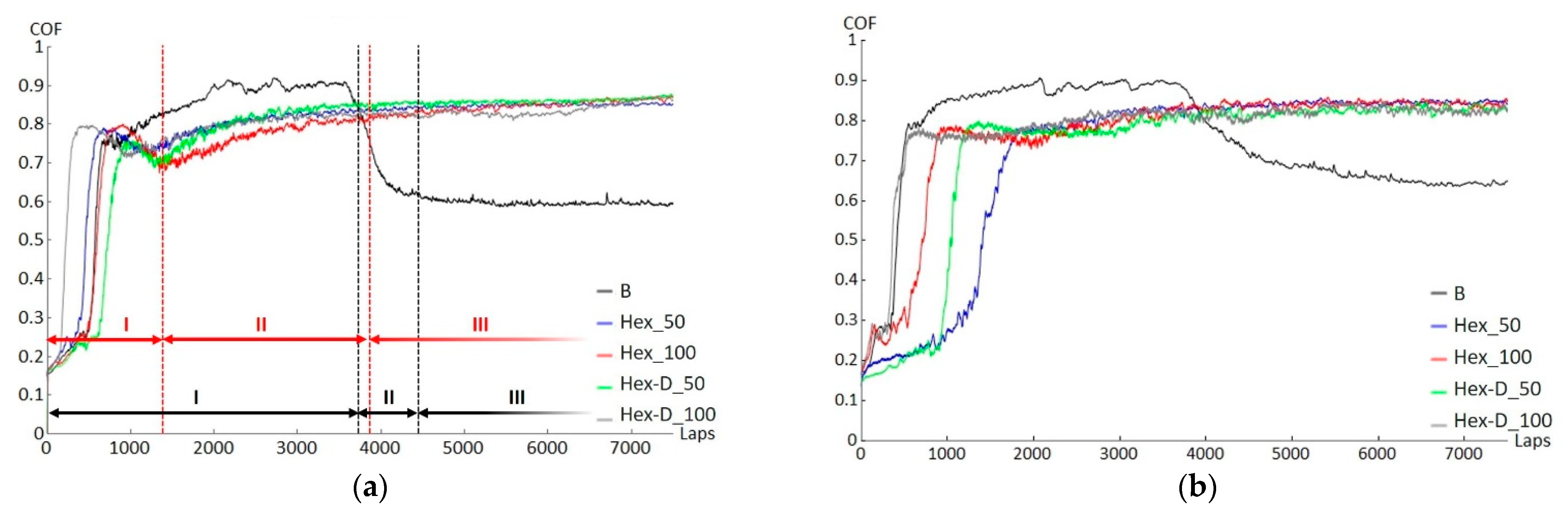
Figure 7.
Wear tracks after 20,000 laps, R10_N5 tests: (a–c) baseline type; (d–f) Hex_50 type; (g–i) Hex-D_50 type.
Figure 7.
Wear tracks after 20,000 laps, R10_N5 tests: (a–c) baseline type; (d–f) Hex_50 type; (g–i) Hex-D_50 type.

Figure 8.
Micrographs of wear debris from dry sliding test at different magnifications.

Figure 9.
Wear tracks on balls after 20,000 laps, R10_N5 tests; (a) baseline type, (b) Hex_50 type, (c) Hex-D_50 type.
Figure 9.
Wear tracks on balls after 20,000 laps, R10_N5 tests; (a) baseline type, (b) Hex_50 type, (c) Hex-D_50 type.
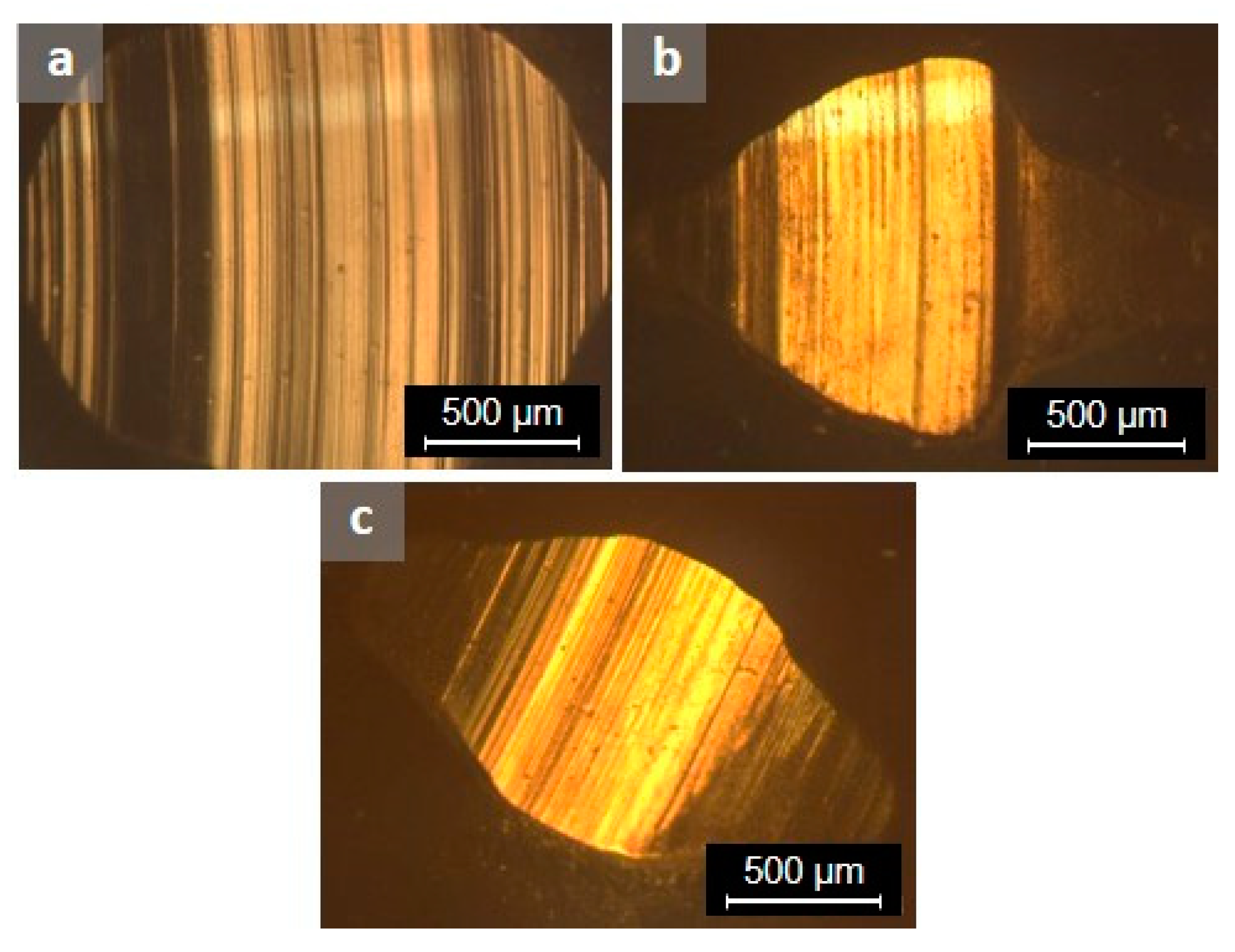
Figure 10.
Specific wear rate from tribological tests after 20,000 laps.

Figure 11.
Coefficient of friction for lubricated tests at a sliding radius of 13.5 mm and normal load 5 N (R13.5_N5_L).
Figure 11.
Coefficient of friction for lubricated tests at a sliding radius of 13.5 mm and normal load 5 N (R13.5_N5_L).

Figure 12.
Sliding pair, geometrical effect related to the actual shape of the 3D-printed features.
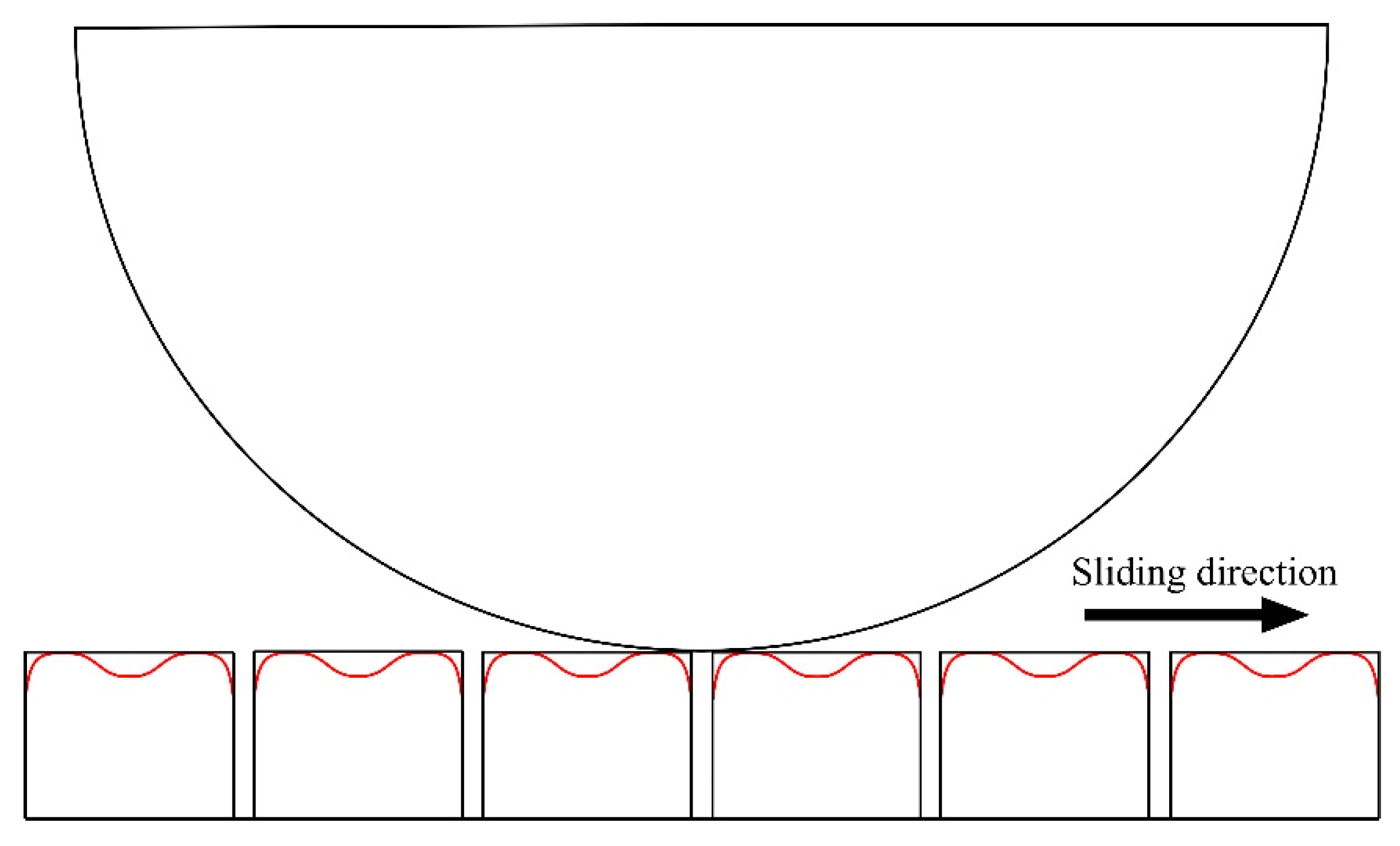
Figure 13.
Wear tracks, after 20,000 laps, R13.5_N5_L lubricated tests; (a,b) baseline, (c) Hex_50 type, (d) Hex-D_50 type.
Figure 13.
Wear tracks, after 20,000 laps, R13.5_N5_L lubricated tests; (a,b) baseline, (c) Hex_50 type, (d) Hex-D_50 type.
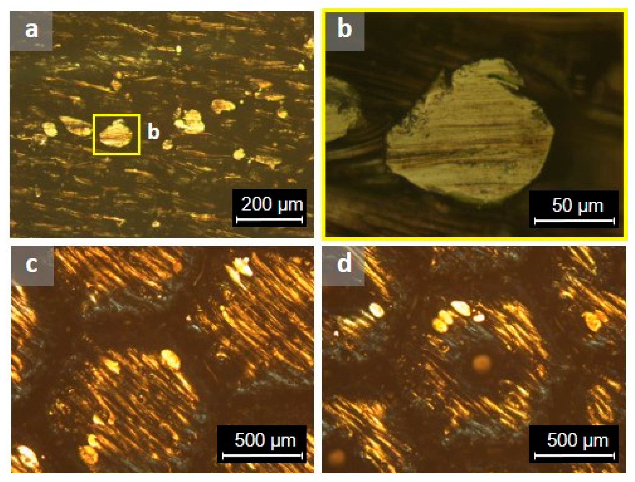
Figure 14.
Lubricant traces on samples, after 20,000 laps, R13.5_N5_L lubricated tests; (a) traces in between laser scanning tracks, (b) traces on the bottom of gaps, (c) traces into dimples.
Figure 14.
Lubricant traces on samples, after 20,000 laps, R13.5_N5_L lubricated tests; (a) traces in between laser scanning tracks, (b) traces on the bottom of gaps, (c) traces into dimples.

Table 1.
Main characteristics of the manufacturing system and printing conditions.
| Parameter | Value |
|---|---|
| Maximum fiber laser power Pmax (W) | 500 |
| Fiber laser wavelength (nm) | 1064 |
| Detail size along axes (µm) | x = 100, y = 100, z 1 = 40 |
| Laser power (W) | 50% Pmax |
| Scanning speed (mm/s) | 1200 |
| Hatch spacing (µm) | 50 |
| Layer thickness (µm) | 40 |
| Atmosphere | Nitrogen |
1 z-axis is the build direction.
Table 2.
Composition of 17-4 PH stainless steel (3D Systems Company, Rock Hill, SC, USA).
| Element | Fe | Cr | Ni | Cu | Si | Mn | Nb |
|---|---|---|---|---|---|---|---|
| wt % | Balance | 15.00–17.50 | 3.00–5.00 | 3.00–5.00 | <1.00 | <1.00 | 0.15–0.45 |
Table 3.
Baseline dimensions and scaling of the closed-type structures analysed in this work; units in μm.
Table 3.
Baseline dimensions and scaling of the closed-type structures analysed in this work; units in μm.
 | |||||
|---|---|---|---|---|---|
| Dimension | Scale 1 | Scale 2 | Scale 3 | Scale 4 | Scale 5 |
| H | 200 | 400 | 600 | 800 | 1000 |
| L | 340 | 680 | 1020 | 1360 | 1700 |
| D | 100 | 200 | 300 | 400 | 500 |
| d | 100 | 200 | 300 | 400 | 500 |
Note. Each scale is obtained by multiplying the baseline Scale 1 times a factor. For example, Scale 3 = Scale 1 × 3.
Table 4.
Experimental conditions employed in the ball-on-disk tribological tests.
| Testing Conditions | Dry | Lubricated |
|---|---|---|
| Sliding radius (mm) | 5, 10 | 13.5 |
| Normal load (N) | 2, 5 | 5 |
| Sliding speed (m/s) | 0.1 | 0.1 |
| Stop condition (laps) | 20,000 | 20,000 |
Table 5.
Nomenclature for tribological tests.
| Sample Type: T, d; Testing Conditions: Ry, Nz, L | |
|---|---|
| T | Sample type: Hexagonal (Hex), Hexagonal with dimples (Hex-D), Baseline (B). |
| d | Distance between prisms in µm (for patterned samples) |
| Ry | Sliding radius in mm |
| Nz | Normal load in N |
| L | If present in nomenclature, it refers to a lubricant-impregnated test |
Note: d, y and z are numbers.
Publisher’s Note: MDPI stays neutral with regard to jurisdictional claims in published maps and institutional affiliations. |
© 2021 by the authors. Licensee MDPI, Basel, Switzerland. This article is an open access article distributed under the terms and conditions of the Creative Commons Attribution (CC BY) license (https://creativecommons.org/licenses/by/4.0/).
Share and Cite
MDPI and ACS Style
Sanguedolce, M.; Zekonyte, J.; Alfano, M. Wear of 17-4 PH Stainless Steel Patterned Surfaces Fabricated Using Selective Laser Melting. Appl. Sci. 2021, 11, 9317. https://doi.org/10.3390/app11199317
AMA Style
Sanguedolce M, Zekonyte J, Alfano M. Wear of 17-4 PH Stainless Steel Patterned Surfaces Fabricated Using Selective Laser Melting. Applied Sciences. 2021; 11(19):9317. https://doi.org/10.3390/app11199317
Chicago/Turabian StyleSanguedolce, Michela, Jurgita Zekonyte, and Marco Alfano. 2021. "Wear of 17-4 PH Stainless Steel Patterned Surfaces Fabricated Using Selective Laser Melting" Applied Sciences 11, no. 19: 9317. https://doi.org/10.3390/app11199317
Note that from the first issue of 2016, this journal uses article numbers instead of page numbers. See further details here.