Article

Design of an Integrated Sub-6 GHz and mmWave MIMO Antenna for 5G Handheld Devices

1
Department of Electrical Engineering, University of Engineering and Technology, Lahore 54890, Pakistan
2
Department of Integrated IT Engineering, Seoul National University of Science and Technology, Seoul 01811, Korea
3
Department of Electrical Engineering, Bahria University Islamabad Campus, Islamabad 44000, Pakistan
4
Department of Electrical Information Technology, Lahore University, Lahore 54590, Pakistan
5
RIMMS, National University of Science and Technology, Islamabad 44000, Pakistan
6
Department of Computer and Communication Engineering, Chungbuk National University, Chengju 28644, Korea
7
College of Engineering, King Saud University, Riyadh 11451, Saudi Arabia
8
Department of Signal Theory and Communications, Universidad Carlos III de Madrid, 28911 Leganés, Madrid, Spain
9
Electronic Engineering Department, University of Rome “Tor Vergata”, Vial Del Politecnico 1, 00133 Rome, Italy
*
Authors to whom correspondence should be addressed.
Appl. Sci. 2021, 11(18), 8331; https://doi.org/10.3390/app11188331
Submission received: 16 June 2021 / Revised: 26 August 2021 / Accepted: 3 September 2021 / Published: 8 September 2021
(This article belongs to the Special Issue Millimeter-wave and Terahertz Applications of Metamaterials)

Abstract

:
The reported work demonstrates the design and realization of an integrated mid-band (sub-6 GHz) and mmWave multiple input, multiple output (MIMO) antenna for 5G handheld devices. The proposed prototype consists of the two-port MIMO configuration of the mid-band antenna placed at the top and bottom of the substrate, while the 4-port mmWave MIMO antenna is placed sideways. The MIMO configuration at the top and bottom consists of a two-element array to achieve high gain at the mid-band spectrum, while the antennas placed sideways are optimized to cover the 5G-mmWave band spectrum. The overall dimensions of the board were selected the same as the of smartphones, i.e., 151 mm × 72 mm. The mid-band antenna has an operational bandwidth of 2.73 GHz, whereas the mmWave antenna has an impedance bandwidth of 3.85 GHz with a peak gain of 5.29 and 8.57 dBi, respectively. Furthermore, the design is analyzed for the various MIMO performance parameters; it was found that the proposed antennas offer high performance in terms of envelop correlation coefficient (ECC), diversity gain (DG), mean effective gain (MEG) and channel capacity loss (CCL) within operational range. A fabricated prototype was tested and measured results show strong agreement with predicted results. Moreover, the proposed work is compared with state-of-the-art work for the same applications to demonstrate its potential for targeted application.

1. Introduction

In the present era, a lot of wireless communication technologies and systems are available which provide data exchange with high data rates and low loss rate. Currently, the 4th Generation of Communication (4G) also known as Long Term Evolution (LTE) leads all other wireless technology by providing the facility of high data rates and throughput [1]. However, the increased demand of the digital era requires wide bandwidths with high throughputs resulting in the limitation of using the sub-6 GHz band for future communication systems [2]. This forces the researcher towards the exploration of the mmWave spectrum, which has the advantages of wider bandwidth capable of providing higher data rates in comparison to sub 6 GHz bands [3,4]. The electromagnetic (EM) waves radiating at the mmWave spectrum may face various issues, including multipath fading and atmospheric absorption losses [5,6,7]. To deal with these wireless network limitations, the researcher in [8,9,10], suggested MIMO and antenna arrays to be one of the solutions which can overcome the limitations faced by mmWave band spectrums. The antenna arrays are suitable to achieve high gain, while MIMO technologies can help us achieve higher capacity with high data rates and multiple Gbps throughput [8,9,10]. However, the isolation between multiple antennas may affect the device performance; thus, to design MIMO antenna arrays with high isolation, high gain and wider bandwidth, researchers had to adopt various isolation reduction techniques [11,12,13].
On the other hand, handheld devices, including cellular phones, operate using various band spectrums; therefore, single or multiple antennas operating in the spectrums are required. The solution to design a single antenna for multiple bands could not be an optimal solution to handle this problem, due to the different requirements associated with different bands [14]. For an instance, the mid-band for 5G and globally allocated band spectrum for 4G require a compact antenna with wideband characteristics. Moreover, low gain characteristics are not an issue for this band, due to lower power losses in wave propagation. Contrary to this, the mmWave band requires a wider operational bandwidth and high gain with a broadside radiation pattern [15]. These requirements lead to the designing of integrated antennas on the same board for cellular systems. Recently, an enormous amount of work is dedicated to the design of integrated antennas [16,17,18,19,20,21,22,23].
An integrated 4G/5G MIMO antenna system having a two-elements 4G MIMO antenna and an eight-element array antenna for 5G applications is proposed in [16]. The proposed work covers globally allocated Global System for Mobile Communications (GSM) and Universal Mobile Telecommunications System (UMTS) band for 4G and the sub-6 GHz band for 5G applications. A similar work, containing a 12-element MIMO antenna for 4G and 5G bands is reported in [17]. The designs reported in [16,17] have lower gain and radiation efficiency and the designs support only the lower frequency bands. A multi-layered 4G and 5G integrated antenna are proposed in [18]. The antenna offers a peak gain of 4 and 8 dBi in the 4G and 5G bands, respectively. However, no solution for 5G MIMO applications is proposed. Another interesting work consisting of printed F type MIMO antenna for 4G as well as 5G application is proposed in [19]. The paper lacks in reporting MIMO performance analysis for the 5G band and the proposed 4G antenna also has low gain.
A conformal integrated antenna for smartphone applications is proposed in [20]. Researchers achieved a high gain of 9 dBi at 5G band using the metamaterial loading technique, while still having a lower gain of 2.15 dBi at a lower frequency band. Moreover, the work proposed in [21] offers good performance parameters including high gain and wide bandwidth at both targeted bands of 4G and 5G. MIMO configuration for the 4G and 5G designs is not being investigated. Similarly, in [22], a high gain of 7 dBi is achieved for the mmWave band antenna. However, the proposed work has several flaws, including no information for gain and radiation efficiency for the lower band and with no solution for MIMO applications mentioned. On other hand, in [23], researchers proposed a 2-element MIMO antenna for 4G applications integrated with a-4 element MIMO array antenna for 5G mmWave applications. Although high gain and wideband is achieved at a high-frequency band, the design still has several limitations, i.e., the non-inclusion of the entire LTE and lower 5G bands, low isolation between the antenna elements and larger footprint.
Concluding the above literature overview, it can be inferred that the designing of wideband, high gain, low mutual coupling and the compact design-based integrated antenna is still a challenge for the research community. Therefore, this article reports an integrated prototype for the sub-6 GHz (mid-band) and 5G mmWave spectrums, for the 4G LTE and 5G handheld applications. For the two bands, the reported design includes two separate MIMO configurations. In the sub 6 GHz spectrum, the proposed design effectively operates in the lower 5G/4G LTE, i.e., 3.3–4.2, 4.4–5.0, 4.8–5.0 and IMT 2.5–2.690 GHz bands. In addition, the design also operates effectively in the 5G mmWave band, i.e., 24.25–27.5 GHz. Aside from the wide bandwidth coverage, the proposed architecture was meticulously examined in terms of both single and MIMO antenna performance. Owing to the high-performance parameters of the antenna and proper MIMO characteristics, the proposed design may be considered as a potential candidate for mid- and high-band handheld applications.

2. Proposed Integrated Design

The proposed integrated design was modeled and simulated by using one of the standard antenna design and simulation tools, Computer Simulation Technology (CST) Studio. The prototype was designed for smartphones or handheld applications (note: 10 board dimensions were assumed for the design). The proposed prototype was designed using RT/Duorid Rogers 5880 material as the substrate. The material has a relative permittivity εr of 2.2 and a dissipation factor-tanγ of 0.0004. The final optimized design is reported in Figure 1.
In Figure 1, there are two MIMO configurations of the antennas, one along the length and the other along the width. The MIMO configuration consisting of two antennas along the length (one at the top and the other at the bottom) of the board is designed for the 4G LTE and lower 5G bands applications. In this MIMO configuration, each antenna element is a novel array of two linear elements with a parallel microstrip feeding network. The partial ground structure is used with the array antenna. The dimensions of the ground have been optimized to acquire the required characteristics in the desired band. Similarly, the four antennas MIMO configuration along the width of the board is designed for the 5G mmWave band. Each antenna element in this configuration is designed with the defected ground structure (DGS). The DGS for each element is optimized by empirical parametric analysis, with the objective of radiation pattern and gain enhancement in the first place and MIMO performance characteristics improvement in the second place. The optimized dimensions annotated in Figure 1 are reported in Table 1.
The proposed antenna design progression is discussed in two parts. In the first subsection, the mid-band MIMO antenna step-by-step designing is discussed. In the second subsection, the mmWave and high-frequency MIMO antenna design process is explained comprehensively.

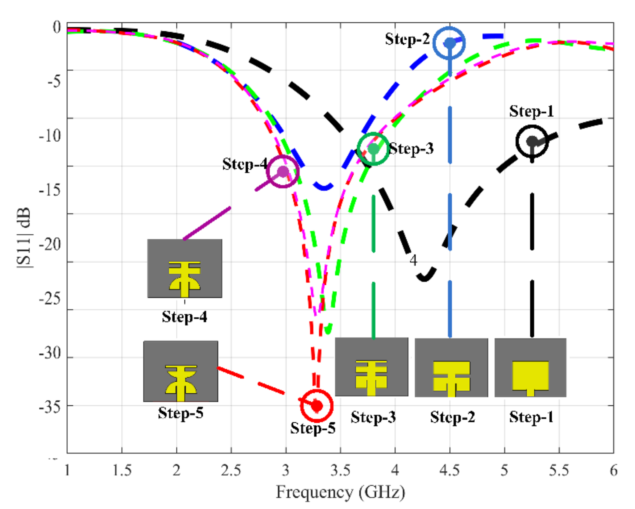
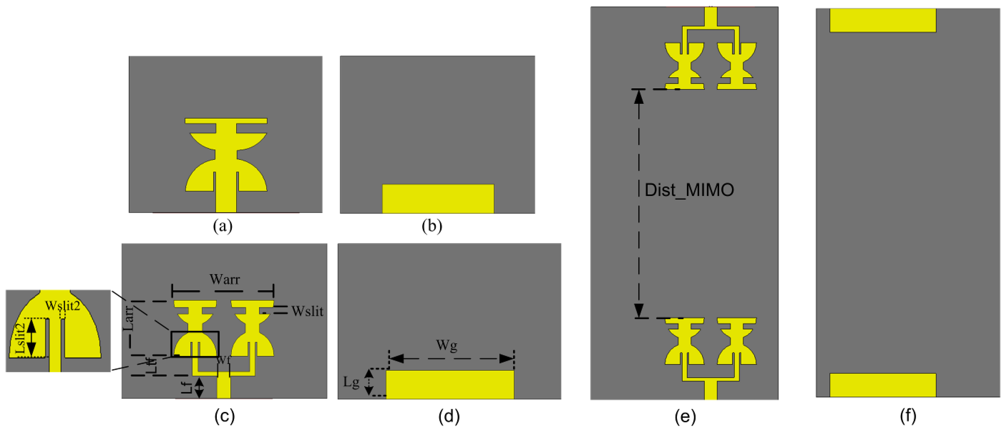
2.1. Mid-Band (4G LTE and Lower 5G) MIMO Configuration

A systematic procedure was followed for the design of the low frequency MIMO configuration. The reported optimized antenna was designed after five evolution stages. In the first stage, standard mathematical Equations (1)–(3) were used for the design of the initial microstrip-fed rectangular patch antenna with complete ground [24]. The S11 parameter for the same stage is reported in Figure 2 as Step-1. It can be observed that the antenna operates as per −10 dB standard, from 3.4 to 6 GHz. However, in order to cover the mentioned applications band, horizontal slits were added into the design, referred to as Stage-2. The dimensions for the slits were optimized using the empirical parametric analysis. The S11 parameter for this stage is reported in Figure 2 as Step-2.
W p = c 2 f c ε r + 1 2
L p = c 2 f o ε r e f f 2 Δ L
where , Δ L = 0.421   h ε reff + 0.3 W s H + 0.264 ε reff 0.258 W s H + 0.8 .
Afterwards, an additional pair of slits were introduced in the upper half part of the design, the position and dimension for the slit were optimized by the use of parametric analysis. The S11 parameter for the modified design is reported in Figure 2 as Step-3. Furthermore, in order to increase the performance of the design, different transformations were applied to the design. After the analysis, it was found that bending in the upper and lower half portion provides good results in terms of better VSWR and matching. The bending was explored at different angles and, after the analysis, it was found that bending the value of 8 generates the best results. The S11 parameter for the fourth and the fifth stage is reported in Figure 2 as Step-4 and Step-5.
After the design of the novel single element, an array for the final antenna design was explored for further improving the gain and bandwidth. The S-parameter for this stage is reported in Figure 3a. Finally, a two-element MIMO configuration for the mid-band applications was designed by placing the final designed array at the top and bottom of the sheet. The location was selected by keeping in view the place of other electronic components for the standard devices.
The detailed annotation and values for the different dimensions for the single, array and MIMO antenna designed for the mid-band are reported in Figure 3 and Table 1.
The S-parameters for the single-element array and MIMO configuration are reported in Figure 4. It can be noted that the designed single element resonates from 2.83 to 4.03 GHz, therefore covering a −10 dB bandwidth of 1.2 GHz (covering lower 5G and 4G LTE bands). However, as a result of gain–bandwidth trade-off, gain in the entire band is not high; therefore, an array configuration for the design was explored. The array was optimized by the use of empirical parametric study analysis. The final optimized array antenna operates from 2.43 to 5.22 GHz, therefore covering a −10 dB bandwidth of 2.79 GHz and covering the 4G LTE and 5G sub 6 GHz bands with maximum IEEE gain of 6.1 dBi, with maximum radiation and total efficiency of 96.3% and 95.4%, respectively. For the fulfillment of the requirement of the data rate, MIMO configuration is a requirement for the 4G LTE and 5G design. Therefore, a two-element MIMO configuration was designed in the final stage. The S-parameters for both MIMO antennas are reported in Figure 4a. It can be noted that both of the antennas have the same S-parameters as that of array antenna, which is an indicator of high isolation. The transmission parameters (|S12| and |S21|) for the configuration are reported in Figure 4b. It can be noted that, even in the worst-case scenario, the isolation between the antenna elements is 28 dB across the entire band.

2.2. High-Band (mmWave 5G) MIMO Configuration

The initial design of the antenna is based on Equations (1)–(3). The same equations were used initially to design the mmWave patch antenna operating at 28 GHz. The antenna was then optimized by the use of the empirical multi-parametric study. The final design was optimized for the mmWave 24.25–28 GHz band. Afterwards, the antenna was used to create a 4-port MIMO configuration. The final single element design, along with the final MIMO design, is shown in the Figure 5.
The S-parameters for the single-element and the MIMO configuration are reported in Figure 6. It can be noted that the designed single element operates from 24.06 to 28 GHz and has an operational −10 dB bandwidth of 3.94 GHz, therefore covering the entire mmWave band-1 (24.25–27.5 GHz) of group 30 (GHz). The maximum IEEE gain of the antenna is 8.57 dBi.
The reflection parameters for the MIMO configurations are also reported in Figure 6a. It can be noted that the operational frequency range for the configuration is from 24.15 to 28 GHz and has an operational −10 dB bandwidth of 3.85 GHz. The MIMO configuration still operates in the required band with maximum IEEE gain of 8.57 dBi and the MIMO sum gain of 13.8 dBi. The transmission parameters for the proposed design are reported in the Figure 6b. It can be noted that, even in the worst-case scenario, the minimum isolation of 30 dB was achieved, which is significantly high.
The distance between the antennas in the MIMO configuration is provided in Figure 7. It can be seen, from Figure 7, that the minimum distance between the two antennas in the mentioned MIMO configuration is 45 mm and the maximum distance between any two antenna elements is 72.31 mm.

2.3. Integrated (4G LTE, Lower 5G and mmWave 5G) MIMO Configuration

The proposed antenna is designed for hybrid handheld devices. Both lower and higher band have their own significance and demand. Therefore, an integrated design for the future smart phone or handheld devices is proposed. The placement of the 4G LTE, lower 5G and mmWave 5G antenna was selected by the empirical parametric study. The integrated design is reported in Figure 1. The S-parameters for all the elements remain the same under integrated environment; therefore, the design may be considered as an appropriate candidate for the integrated mid-band and mmWave 5G applications.

3. Results and Discussion

The hardware manufactured prototype is shown in Figure 8. Here, the Sub Miniature version A (SMA) connectors used for the mmWave 5G-MIMO configuration are K8400A, that has an operational frequency range of up to 40 GHz. The connectors have an impedance of 50 ohm. The connectors belong to the 2.92 mm connector series. The equipment used for the measurements also has an operational range of up to 40 GHz

3.1. Surface Current

The surface current for the various lower band antenna configurations, i.e., single-element, 2-element array and 2-port MIMO antenna, is depicted in Figure 9. It can be noted that, in all the cases when either antenna-1 or antenna-2 is excited while keeping the other elements un-excited, there is non-significant change in the surface current density of the other antenna. This is an indication of good isolation characteristics, or, in other words, the radiating characteristics of any single element remain free from the influence of another element. In addition, it can also be observed that the current density is distributed around feed and patch of each element, which results in the generation of an omni-directional radiation pattern, as explained in briefly in [25].
The surface current for the mmWave MIMO configuration is reported in Figure 10. It can be noted that, in all of the cases in which either antenna-1, antenna-2, antenna-3 or antenna-4 is excited, there is non-significant change in the surface current density of the other antennas, thus showing low influence of the surrounding elements on the performance of the excited element. Moreover, it can also be observed that the maximum current density is around the mid of the patch for both single-element and MIMO antenna configuration, as depicted in Figure 10. It is worthy to note here, that the surface current for the integrated antenna configuration remains identical to the individual MIMO configuration of 4G and 5G antenna system. Thus, the radiation characteristics of both lower and higher frequency antenna system remain unchanged after their integration on the same board.

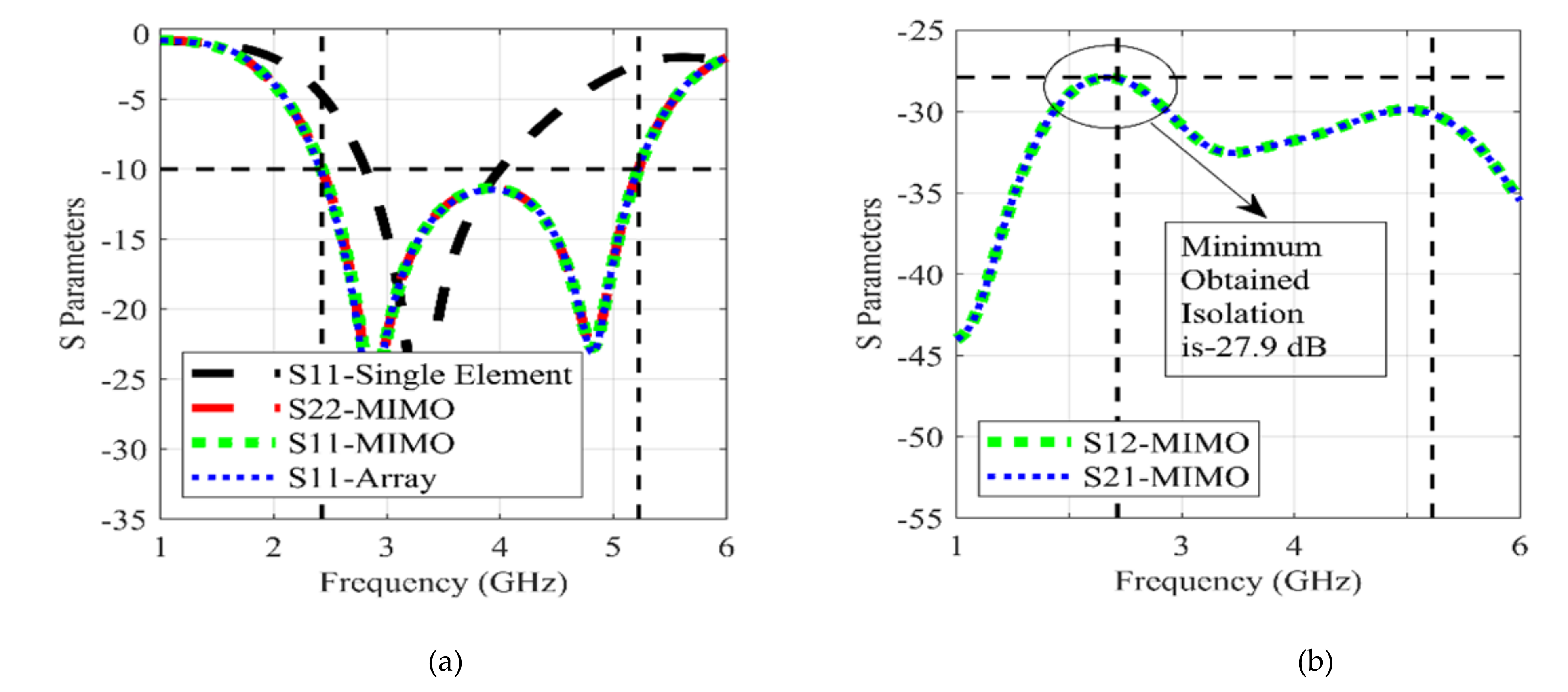
3.2. Scattering Parameters

Scattering parameters, or S-parameters, for each of the MIMO configuration mounted as integrated design were simulated and measured for the understanding and reporting of the practical and simulation characteristics of the design. The Vector Network Analyzer (VNA) used for the measurement of the S-parameters was an Anritsu Shock Line MS46122B. The measurement setup for the S-parameters is reported in Figure 11.
The measured and simulated S-parameters for both MIMO antenna configurations, including reflection and transmission coefficients, are reported in the form of plots in Figure 12.
It can be noted, in Figure 12a, that, for the low-band MIMO configuration, the measured reflection coefficients of both antennas correlate with the simulated results; therefore, the measured operational bandwidth of the design is also the same as that of simulation. The slight change in the characteristics is due to the non-ideal fabrication and mounting of the connectors. Similarly, the reflection coefficients for the mmWave antennas are also reported in Figure 12b. Here, it may also be noted that the measured results correlate with the simulated results. The slight change in the measured traces is due to the non-ideal fabrication and other real time impairments. Similarly, the transmission characteristics for the mmWave are reported in Figure 12c,d.
Here, it may be noted that the minimum isolation achieved is 29.03 dB, which is still high and is indicating good practical isolation characteristics. From the measured results, it may be noted that the effective bandwidth of the antenna, in the practical case, is still the same as that of the claimed simulated bandwidth.

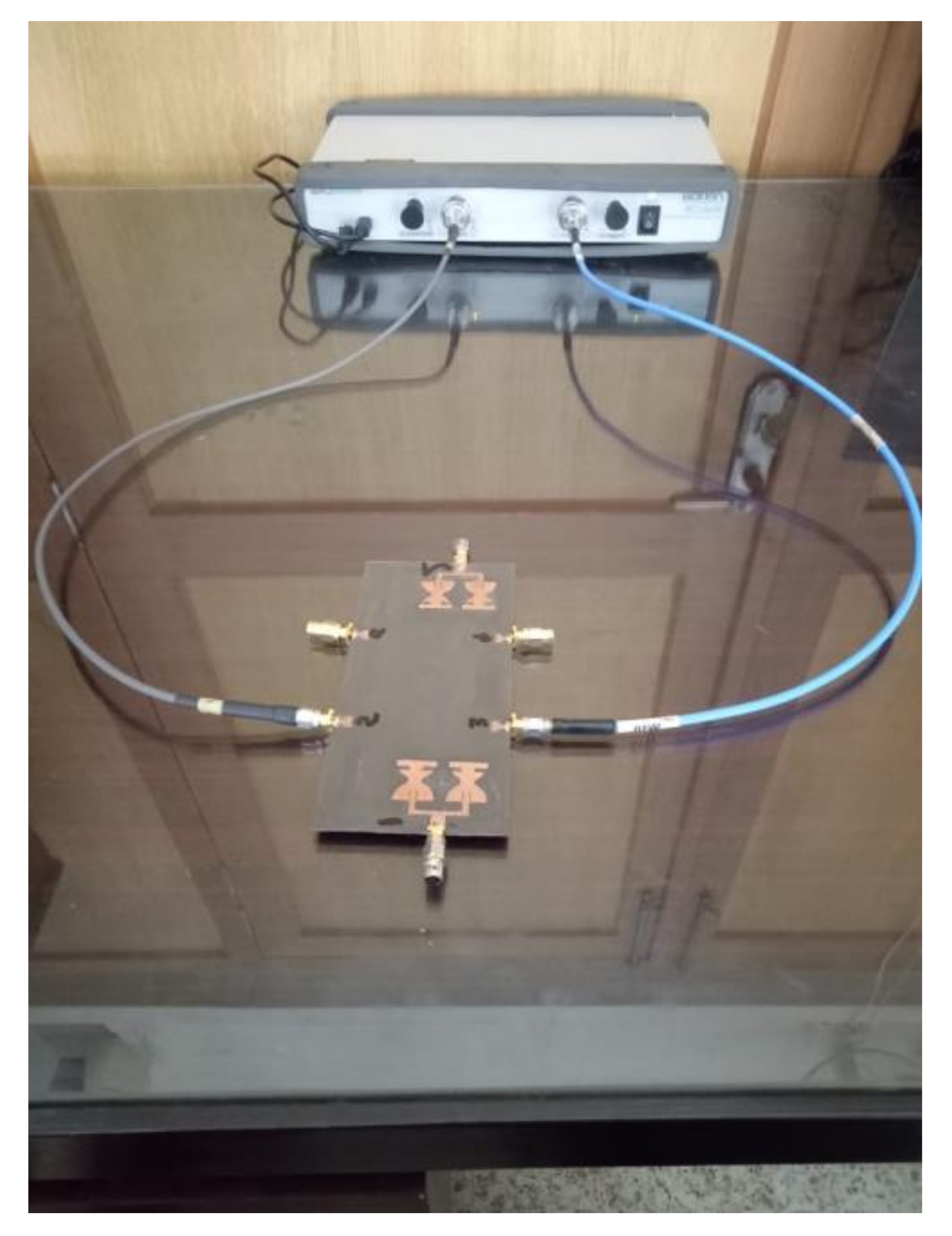
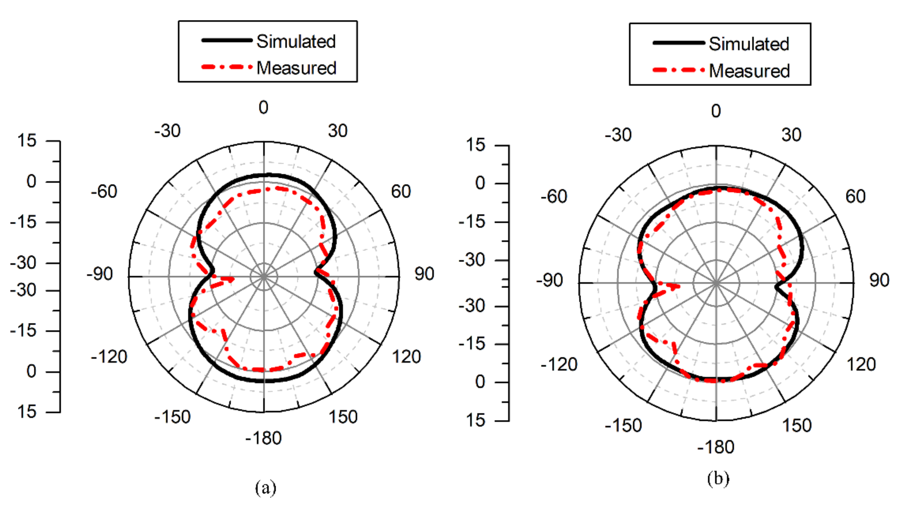
3.3. Far-Field Results

For the verification of the far-field characteristics of the proposed integrated antenna, the fabricated antenna was tested in a shielded RF anechoic chamber. The testing setup images for the mid-band and high-band antennas are shown in Figure 13. The simulated and the measured GAIN results for the integrated antenna design are reported in Table 2. It can be noted that the measured and simulated gain have low residual error.
The 2D radiation patterns of the integrated design are measured in the same chamber as mentioned for the GAIN. The radiation pattern corresponding to theta = 90 and phi = 90 plane for the simulated and measured radiation pattern at 3.8 GHz are reported in Figure 14. Similarly, the simulated and measured radiation patterns at 27.5 GHz are reported in Figure 15. Here, it can be noted that, at both frequencies, the simulated and measured radiation patterns have a good correlation with each other; however, at the lower frequency of 3.8 GHz, slight differences were observed, which are due to manufacturing impairments, while, at the higher frequency of 27.5 GHz, some ripples showed up because of unavoidable mismatches that happen at the higher frequency.
The measured and simulated radiation patterns are different due to the non-ideal manufacturing process and the limitation of the testing and measuring equipment. In spite of such impairments, it can be noted that radiation patterns are still good enough for practical use.

3.4. MIMO Performance Analysis

The MIMO performance of the proposed design was analyzed using envelop correlation coefficient (ECC), diversity gain (DG), channel capacity loss (CCL) and mean effective gain (MEG). The detailed analyses for each of the parameters are reported in the relevant sections below.

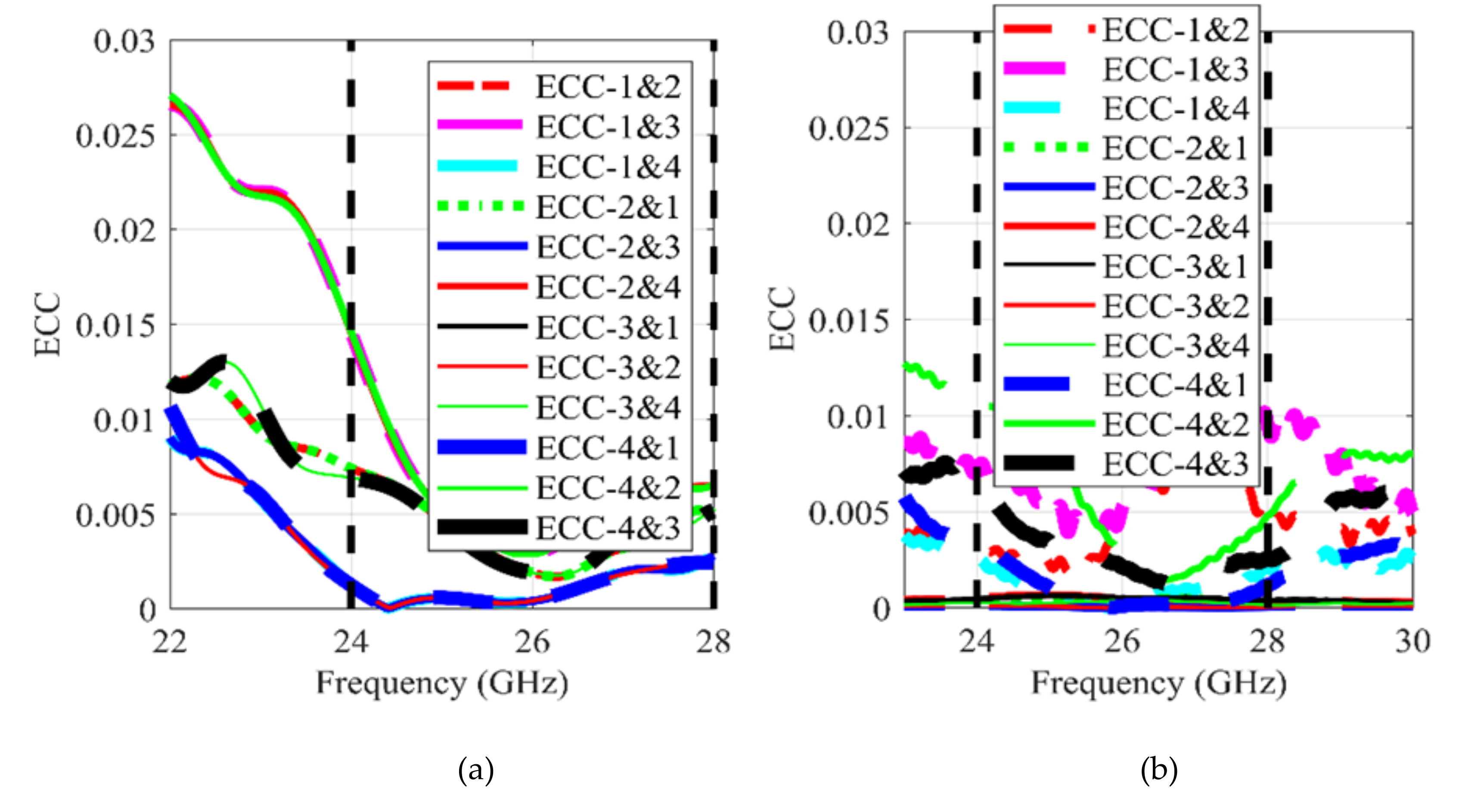
3.4.1. Envelop Correlation Coefficient

The envelop correlation coefficient for a MIMO configuration can be directly measured using a 3D chamber, or can be calculated using Equation (4), provided in [26].
ρ i j 2 = S i i * S i j + S j i * S j j 1 S i i 2 S j i 2 1 S j j 2 S i j 2 η r a d i η r a d j
Equation (4) is used to calculate the value of the ECC between the antenna element i and j . For 4G wireless devices, the allowed limit for the ECC is 0.3. The envelop correlation coefficient for the mid-band MIMO configuration is reported in Figure 16 and for high-band is reported in Figure 17. The values for the ECC are meaured by using the above-mentioned method. Here, it can be noted that the value of the ECC (measured and simulated) for both configurations is within the allowed operational range for the designed bands.

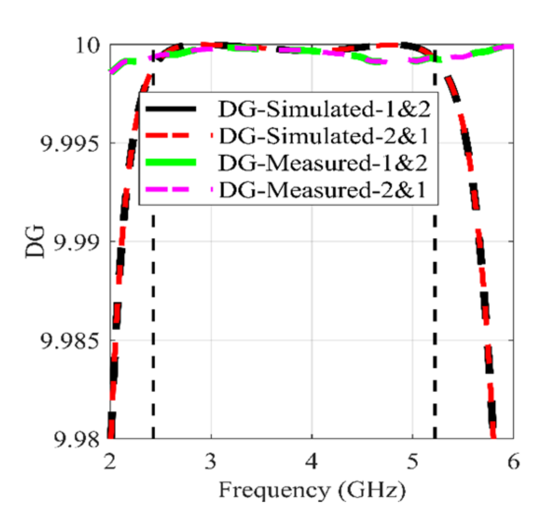
3.4.2. Diversity GAIN

Diversity gain is a MIMO performance parameter that is used to capture the effect of spatial diversity, especially in a MIMO system. The more the received signals are uncorrelated, the higher is the value of the parameter. The diversity gain for a MIMO system can be calculated using Equation (5).
Diversity   Gain = γ c S N R c γ 1 S N R 1 P γ c < γ s / S N R
The plots for the simulation- and measurement-based DG for the mid-band and high-band MIMO configurations are reported in Figure 18 and Figure 19. Here, it can be noted that the values of the DG for both simulation and measurement achieve the typical range of the DG (reported in the literature).

3.4.3. Mean Effective Gain

For MIMO systems, independent antenna gain cannot be considered as the final performance metric. In addition to the typical standalone antenna gain, the mean effective gain was introduced; it is indicative of the gain performance of the antenna in a MIMO configuration. The typical formulae reported in the literature for the computation or determination of the M E G is reported below [27].
M E G i = 0.5 µ irad = 0.5 ( 1 i = 1 K | S i j | )
The typical range for the M E G is from −12 to −3. The M E G s based on simulation and hardware measurements are reported in Figure 20 and Figure 21, for mid-band and high-band, respectively. Here, it can be noted the values for the M E G for all of the antennas in both of the MIMO configurations are within the allowed range. So, the antennas are not only performing well in the standalone, but also in the MIMO environment.

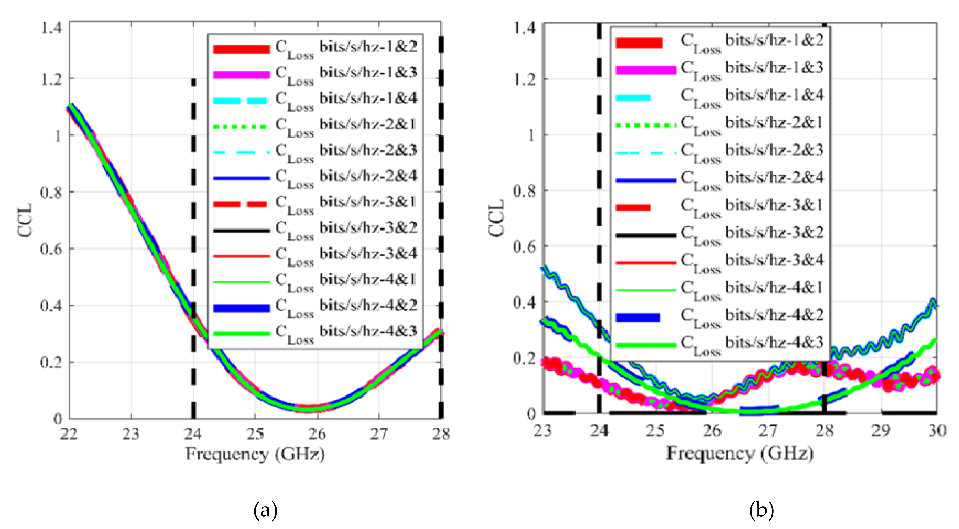
3.4.4. Channel Capacity Loss (CCL)

The channel capacity loss is an indicator for understanding the change in capacity due to the MIMO environment. The CCL for the MIMO antenna can be calculated by the equation reported in Equation (7), provided in [26,27].
( loss ) = log 2 d e t a
where
a = σ 11 σ 12 σ 21 σ 22 σ i i = 1 S i i 2 S i j 2 σ i i = S i i * S i i + S i i S i i *
The typical value considered as the upper limit for the performance parameter is 0.4. The CCLs based on the simulation and measurements are reported in Figure 22 and Figure 23. The values of the CCL for the simulated and the measured results is below 0.4.

3.5. Comparative Analysis

The summary for comparative analysis of the proposed design is reported in Table 3. The design reported in [16] provides the mid-band bandwidth of 0.2 GHz (3.4–3.6), whereas the proposed design provides a mid-bandwidth of 2.79 GHz; in addition to that, it can be noted that, in all other figures of merit, the proposed design provides even better performance. In [17], the reported design has an operation −6 dB bandwidth (in the best case) of 0.4 GHz, in the 5G lower band, and of 0.775 GHz (5.15–5.925) in another band. The 0.4 GHz range is 3.4–3.8 GHz, as per −6 dB standard. In comparison, the proposed design provides a continuous −10 dB bandwidth of 2.79 GHz, covering 4G LTE and a complete lower 5G band. In all of the other mentioned performance metrics, the proposed design showed better performance. The design reported in [18] is a multi-layer design with the antenna dimension significantly larger than that of our proposed design. In addition to that, the reported design (in [18]) does not cover the complete lower 5G band. The gain of the reported low- or mid-band design is lower than that of our proposed design. The operational bandwidth and gain reported for the low- and high-frequency bands are lower than our proposed bandwidth and gain; therefore, the proposed design is a better option than the reported design. In [20], a design based on the conformal approach was proposed. The mid-band characteristics of the reported design are comparatively lower than those of our proposed design. In the high-band, the operational bandwidth of the reported design is 2.01 GHz (between 26.99 and 29 GHz), whereas our proposed design has an operational bandwidth of 3.85 GHz (24.15–28 GHz), covering a mmWave band from 24.25 to 27.5 GHz. Therefore, keeping in view the bandwidth and gain trade-off, our proposed design has better performance than the design reported in [20]. Our design offers 8.57 dBi gain at 28 GHz with a bandwidth of 3.85 GHz. In addition to that, the gain of 9 dB in the reported design’s performance characteristics is not constant in the entire band. In [21], the reported design has an array configuration in the mid-band. The footprint of the reported antenna is larger than that of our proposed antenna. The reported design offers a bandwidth in chunks of 0.16 and 0.55 GHz, whereas our proposed design has a continuous bandwidth of 2.79 GHz. The gain–bandwidth trade-off of the proposed design, along with efficiency and all other figures of merit, is better than the reported design in mid-band. The mmWave antenna reported in [20] is also an array, with a footprint far bigger than the proposed design, with a bandwidth of 1.3 GHz. The proposed design has an operational bandwidth of 3.83 GHz in the high-band; so, our proposed design is better in performance than the design reported in [21], in terms of gain–bandwidth trade-off and compactness. The design reported in [22] is lower in performance in almost every aspect than our proposed design. In [23], an integrated design for lower 5G and mmWave was reported. The lower band or mid-band MIMO antenna has an operational bandwidth of 0.28 GHz, which is low, as compared to our proposed design, offering 2.79 GHz of bandwidth. The proposed design provides better performance in all of the other figures of merit. The design also reported a MIMO antenna configuration in the mmWave 5G band. The antenna reported for this band is also an array and has a footprint bigger than our proposed antenna. Moreover, the isolation offered by our proposed design is 29 dB or higher and the isolation of the design reported in [23] is 28 dB or higher. Therefore, our proposed design offers better isolation. In addition to that, the radiation efficiency of our proposed design is also higher. Therefore, our proposed design can be considered as a good alternative to the design reported in [23].
After the analysis, it was observed that the size of our proposed patch for mid-band and mmWave antennas is comparatively smaller than that of the other reported antennas [18,19,20,21,22,23]. In addition to that, the proposed antenna is operational for the 4G LTE, lower 5G and mmWave 5G applications. The proposed design covers the complete sub-6GHz (5G band) and 24.25–27.5 GHz mmWave band. It was also found that our proposed design scheme has the highest (27.9 dB) isolation in mid-band MIMO case, as well as in mmWave 2D planner antenna case (29 dB). In addition to that, the proposed design has desirable MIMO characteristics (all within allowed limits). Therefore, our proposed integrated antenna configuration can be considered as a good candidate for the reported applications.

4. Conclusions

In this paper, an integrated patch antenna is proposed. The proposed prototype consists of two different MIMO configurations, one referred to as mid-band MIMO configuration and the other as mmWave 5G MIMO configuration. The complete progression of the design is explained in detail and the design is analyzed in-depth for the analysis of the performance. After the analysis, it was found that the proposed MIMO configurations have the highest isolation, when compared with 2D Flat (single or multilayer) antenna structures, and second highest in the mmWave band, when compared with conformal antenna structures. The proposed design has all the MIMO performance parameters within range, with the best values, when compared with 2D flat antenna designs. Therefore, the design can be used for the integrated mid-band and 5G-mmWave applications.

Author Contributions

Conceptualization, H.K., W.A.A. and M.A. (Mudassir Ali); methodology, software and validation, H.K., M.H., A.F. and N.H., S.K., M.A. (Mohammad Alibakhshikenari) and E.L.; formal analysis, investigation, resources and data curation, W.A.A., N.H. and M.A. (Mohammad Alibakhshikenari); writing—original draft preparation, H.K., A.F. and M.H.; writing—review and editing, W.A.A., N.H., S.K., M.A. (Mohammad Alibakhshikenari) and E.L.; measurements, M.A. (Mudassir Ali); project administration, M.A. (Mohammad Alibakhshikenari) and E.L. All authors have read and agreed to the published version of the manuscript.

Funding

This project has received funding from Universidad Carlos III de Madrid and the European Union’s Horizon 2020 research and innovation program under the Marie Sklodowska-Curie grant Agreement No 801538. As well as, this work was partially supported by the Antenna and Wireless Propagation Group (https://sites.google.com/view/awpgrp/home accessed on 16 June 2021). In addition, it received funding from the Researchers Supporting Project number (RSP-2021/58), King Saud University, Riyadh, Saudi Arabia.

Institutional Review Board Statement

Not applicable.

Informed Consent Statement

Not applicable.

Data Availability Statement

All date have been included within the manuscript.

Acknowledgments

The authors appreciate financial support from Universidad Carlos III de Madrid and the European Union’s Horizon 2020 research and innovation program under the Marie Sklodowska-Curie grant Agreement No 801538. As well as, this work was partially supported by the Antenna and Wireless Propagation Group (https://sites.google.com/view/awpgrp/home accessed on 16 June 2021) and from the Researchers Supporting Project number (RSP-2021/58), King Saud University, Riyadh, Saudi Arabia.

Conflicts of Interest

The authors declare no conflict of interest.

References

  1. Global Mobile Suppliers Association. The Road to 5G: Drivers, Applications, Requirements and Technical Development: A GSA Executive Report from Ericsson, Huawei and Qualcomm; Global Mobile Suppliers Association: Farnham, UK, 2015. [Google Scholar]
  2. Rappaport, T.S.; Sun, S.; Mayzus, R.; Zhao, H.; Azar, Y.; Wang, K.; Wong, G.N.; Schulz, J.K.; Samimi, M.; Gutierrez, F. Millimeter wave mobile communications for 5G cellular: It will work! IEEE Access 2013, 1, 335–349. [Google Scholar] [CrossRef]
  3. Ghaffar, A.; Li, X.J.; Abbas Awan, W.A.; Iffat Naqvi, S.I.; Hussain, N.; Seet, B.C.; Alibakhshikenari, M.; Falcone, F.; Limiti, E. Design and Realization of a Frequency Reconfigurable Multimode Antenna for ISM, 5G-Sub-6-GHz, and S-Band Applications. Appl. Sci. 2021, 11, 1635. [Google Scholar] [CrossRef]
  4. Pi, Z.; Khan, F. An introduction to millimeter-wave mobile broadband systems. IEEE Commun. Mag. 2011, 49, 101–107. [Google Scholar] [CrossRef]
  5. Andrews, J.G.; Buzzi, S.; Choi, W.; Hanly, S.V.; Lozano, A.; Soong, A.C.; Zhang, J.C. What will 5G be? IEEE J. Sel. Areas Commun. 2014, 32, 1065–1082. [Google Scholar] [CrossRef]
  6. Naqvi, A.H.; Lim, S. Review of recent phased arrays for millimeter-wave wireless communication. Sensors 2018, 18, 3194. [Google Scholar] [CrossRef] [PubMed] [Green Version]
  7. Salamin, M.A.; Hussain, N.; Le, T.T. A 2 × 1 array-based wideband mm-wave antenna integrated with a 2-element multiple-input-multiple-output antenna for 5G mobile terminals. Int. J. RF Microw. Comput.-Aided Eng. 2021, 31, e22709. [Google Scholar] [CrossRef]
  8. Jilani, S.F.; Alomainy, A. Millimetre-wave T-shaped MIMO antenna with defected ground structures for 5G cellular networks. IET Microw. Antennas Propag. 2018, 12, 672–677. [Google Scholar] [CrossRef]
  9. Zaidi, A.; Baghdad, A.; Awan, W.A.; Faleh, S.; Ballouk, A.; Badri, A. Analysis and optimisation of 8× 1 double ‘U’ slotted patch array for future 5G communications. Int. J. Syst. Control Commun. 2020, 11, 305–319. [Google Scholar] [CrossRef]
  10. Awan, W.A.; Zaidi, A.; Hussain, N.; Khalid, S.; Baghdad, A. Characterization of dual band MIMO antenna for 25 GHz and 50 GHz applications. In Proceedings of the International Conference on Computing, Electronic and Electrical Engineering (ICE Cube), Quetta, Pakistan, 12–13 November 2018; pp. 1–4. [Google Scholar]
  11. Ding, H.Z.; Jiao, Y.C.; Ni, T. A compact multiband printed antenna for smart-phone applications. Microw. Opt. Technol. Lett. 2015, 57, 2289–2294. [Google Scholar] [CrossRef]
  12. Li, J.F.; Wu, D.L.; Huang, B.; Wu, Y.J. A LTE smartphone antenna with an internal matching circuit to cover 698--2710 MH z. Microw. Opt. Technol. Lett. 2017, 59, 2405–2411. [Google Scholar] [CrossRef]
  13. Liang, Y.W.; Zhou, H.M. Small-size LTE/WWAN planar printed antenna for ultrathin smartphone application. Microw. Opt. Technol. Lett. 2015, 57, 2116–2120. [Google Scholar] [CrossRef]
  14. Khalid, M.; Iffat Naqvi, S.; Hussain, N.; Rahman, M.; Mirjavadi, S.S.; Khan, M.J.; Amin, Y. 4-Port MIMO antenna with defected ground structure for 5G millimeter wave applications. Electronics 2020, 9, 71. [Google Scholar] [CrossRef] [Green Version]
  15. Iqbal, A.; Basir, A.; Smida, A.; Mallat, N.K.; Elfergani, I.; Rodriguez, J.; Kim, S. Electromagnetic bandgap backed millimeter-wave MIMO antenna for wearable applications. IEEE Access 2019, 7, 111135–111144. [Google Scholar] [CrossRef]
  16. Ban, Y.L.; Li, C.; Wu, G.; Wong, K.L. 4G/5G Multiple Antennas for Future Multi-Mode Smartphone Applications. IEEE Access 2016, 4, 2981–2988. [Google Scholar] [CrossRef]
  17. Li, Y.; Luo, Y.; Yang, G. 12-port 5G Massive MIMO antenna array in sub-6GHz mobile handset for LTE bands 42/43/46 applications. IEEE Access 2018, 6, 344–354. [Google Scholar] [CrossRef]
  18. Hussain, R.; Alreshaid, A.T.; Podilchak, S.K.; Sharawi, M.S. Compact 4G MIMO antenna integrated with a 5G array for current and future mobile handsets. IET Microw. Antennas Propag. 2017, 11, 271–279. [Google Scholar] [CrossRef] [Green Version]
  19. Ikram, M.; Hussain, R.; Sharawi, M.S. 4G/5G antenna system with dual function planar connected array. IET Microw. Antennas Propag. 2017, 11, 1760–1764. [Google Scholar] [CrossRef]
  20. Magray, M.I.; Karthikeya, G.S.; Muzaffar, K.; Koul, S.K. Compact Co-design of Conformal 4G LTE and mmWave 5G Antennas for Mobile Terminals. IETE J. Search 2019. [Google Scholar] [CrossRef]
  21. Naqvi, S.I.; Naqvi, A.H.; Arshad, F.; Riaz, M.A.; Azam, M.A.; Khan, M.S.; Amin, Y.; Loo, J.; Tenhunen, H. An Integrated Antenna System for 4G and Millimeter-Wave 5G Future Handheld Devices. IEEE Access 2019, 7, 116555–116566. [Google Scholar] [CrossRef]
  22. Kurvinen, J.; Kähkönen, H.; Lehtovuori, A.; Ala-Laurinaho, J.; Viikari, V. Co-Designed mm-Wave and LTE Handset Antennas. IEEE Trans. Antennas Propag. 2018, 67, 1545–1553. [Google Scholar] [CrossRef]
  23. Iffat Naqvi, S.; Hussain, N.; Iqbal, A.; Rahman, M.; Forsat, M.; Mirjavadi, S.S.; Amin, Y. Integrated LTE and millimeter-wave 5G MIMO antenna system for 4G/5G wireless terminals. Sensors 2020, 20, 3926. [Google Scholar] [CrossRef] [PubMed]
  24. Balanis, C.A. Antenna Theory: Analysis and Design; John Wiley & Sons: Hoboken, NJ, USA, 2015. [Google Scholar]
  25. Awan, W.A.; Zaidi, A.; Hussain, N.; Iqbal, A.; Baghdad, A. Stub loaded, low profile UWB antenna with independently controllable notch-bands. Microw. Opt. Technol. Lett. 2019, 61, 2447–2454. [Google Scholar] [CrossRef]
  26. Hussain, N.; Awan, W.A.; Ali, W.; Naqvi, S.I.; Zaidi, A.; Le, T.T. Compact wideband patch antenna and its MIMO configuration for 28 GHz applications. AEU-Int. J. Electron. Commun. 2021, 132, 153612. [Google Scholar] [CrossRef]
  27. Zahra, H.; Awan, W.A.; Ali, W.A.; Hussain, N.; Abbas, S.M.; Mukhopadhyay, S. A 28 GHz Broadband Helical Inspired End-Fire Antenna and Its MIMO Configuration for 5G Pattern Diversity Applications. Electronics 2021, 10, 405. [Google Scholar] [CrossRef]
Figure 1. Geometry of the proposed integrated design: (a) top view; (b) back view.
Applsci 11 08331 g001
Figure 2. Return loss for different progression stages for mid-band antenna element.
Applsci 11 08331 g002
Figure 3. Mid-band MIMO final antenna design progression stages: (a) single element, front; (b) single element, back; (c) array, front; (d) array, back; (e) MIMO antenna configuration, front; (f) MIMO antenna configuration, back.
Applsci 11 08331 g003
Figure 4. Scattering parameters for the mid-band (4G LTE and lower 5G) antenna design: (a) reflection; (b) transmission.
Applsci 11 08331 g004
Figure 5. High-band (5G-mmWave) MIMO antenna design: (a) front view; (b) back view.
Applsci 11 08331 g005
Figure 6. Scattering parameters for the high-band (mmWave) antenna design: (a) reflection; (b) transmission.
Applsci 11 08331 g006
Figure 7. A 4-port mmWave MIMO configuration.
Applsci 11 08331 g007
Figure 8. Hardware prototype for the integrated design: (a) front view; (b) back view.
Applsci 11 08331 g008
Figure 9. Surface current for the mid-band MIMO final and progression stages: (a) single-element surface current distribution; (b) array surface current distribution; (c) MIMO-1 surface current distribution; (d) MIMO-2 surface current distribution.
Applsci 11 08331 g009
Figure 10. Surface current for the high-band MIMO final: (a) single element surface current distribution; (b) MIMO-1 surface current distribution; (c) MIMO-2 surface current distribution; (d) MIMO-3 surface current distribution; (e) MIMO-4 surface current distribution.
Applsci 11 08331 g010
Figure 11. S-parameter measurement hardware setup.
Applsci 11 08331 g011
Figure 12. Scattering parameters for the mid-band (4G LTE and lower 5G) and high-band (5G mmWave) MIMO antennas integrated design: (a) measured and simulated scattering parameters for the mid-band (4G LTE and lower 5G) MIMO configuration; (b) measured and simulated reflection parameters for the high-band (5G mmWave) MIMO configuration; (c) simulated transmission parameters for the high-band (5G mmWave) MIMO configuration; (d) measured transmission parameters for the high-band (5G mmWave) MIMO configuration.
Applsci 11 08331 g012
Figure 13. Antenna far field-testing setup: (a) mounted high-band (5G mmWave) antenna; (b) mounted mid-band MIMO, front; (c) mounted mid-band MIMO, back.
Applsci 11 08331 g013
Figure 14. Radiation pattern for the mid-band MIMO antenna: (a) measured and simulated radiation pattern for phi = 90° at 3.8 GHz; (b) measured and simulated radiation pattern for theta = 90° at 3.8 GHz.
Applsci 11 08331 g014
Figure 15. Radiation pattern for the high-band MIMO antenna: (a) measured and simulated radiation pattern for phi = 90° at 27.5 GHz; (b) measured and simulated radiation pattern for theta = 90° at 27.5 GHz.
Applsci 11 08331 g015
Figure 16. The measured and simulated ECC for mid-band MIMO configuration.
Applsci 11 08331 g016
Figure 17. The measured and simulated ECC for mmWave MIMO configuration: (a) simulated ECC; (b) measured ECC.
Applsci 11 08331 g017
Figure 18. The measured and simulated DG for mid-band MIMO configuration.
Applsci 11 08331 g018
Figure 19. The measured and simulated DG for mmWave MIMO configuration: (a) simulated DG; (b) measured DG.
Applsci 11 08331 g019
Figure 20. The measured and simulated MEG for mid-band MIMO configuration.
Applsci 11 08331 g020
Figure 21. The measured and simulated MEG for mmWave MIMO configuration: (a) simulated MEG; (b) measured MEG.
Applsci 11 08331 g021
Figure 22. The measured and simulated CCL for mid-band MIMO configuration.
Applsci 11 08331 g022
Figure 23. The measured and simulated CCL for mmWave MIMO configuration: (a) simulated CCL; (b) measured CCL.
Applsci 11 08331 g023
Table 1. Dimensions of the proposed design.
NameValue (mm)NameValue (mm)
Mid-Band Single and MIMO (4G LTE and Lower 5G) antenna
Lf7.25Wslit2.2
Warr35Wf4.85
Larr17.86Ltf6.44
Lslit24.5Wslit20.61
Wg41.16Lg9.25
High-Band Single and MIMO (5G mmWave band) antenna
Wpm5Lfm2
Lpm7.6Wfm5.25
TFm3Lpt2.6
SW0.8SL0.5
Wmg10.25Lmg10
Gsw1.99gsl3
Integrated MIMO antenna
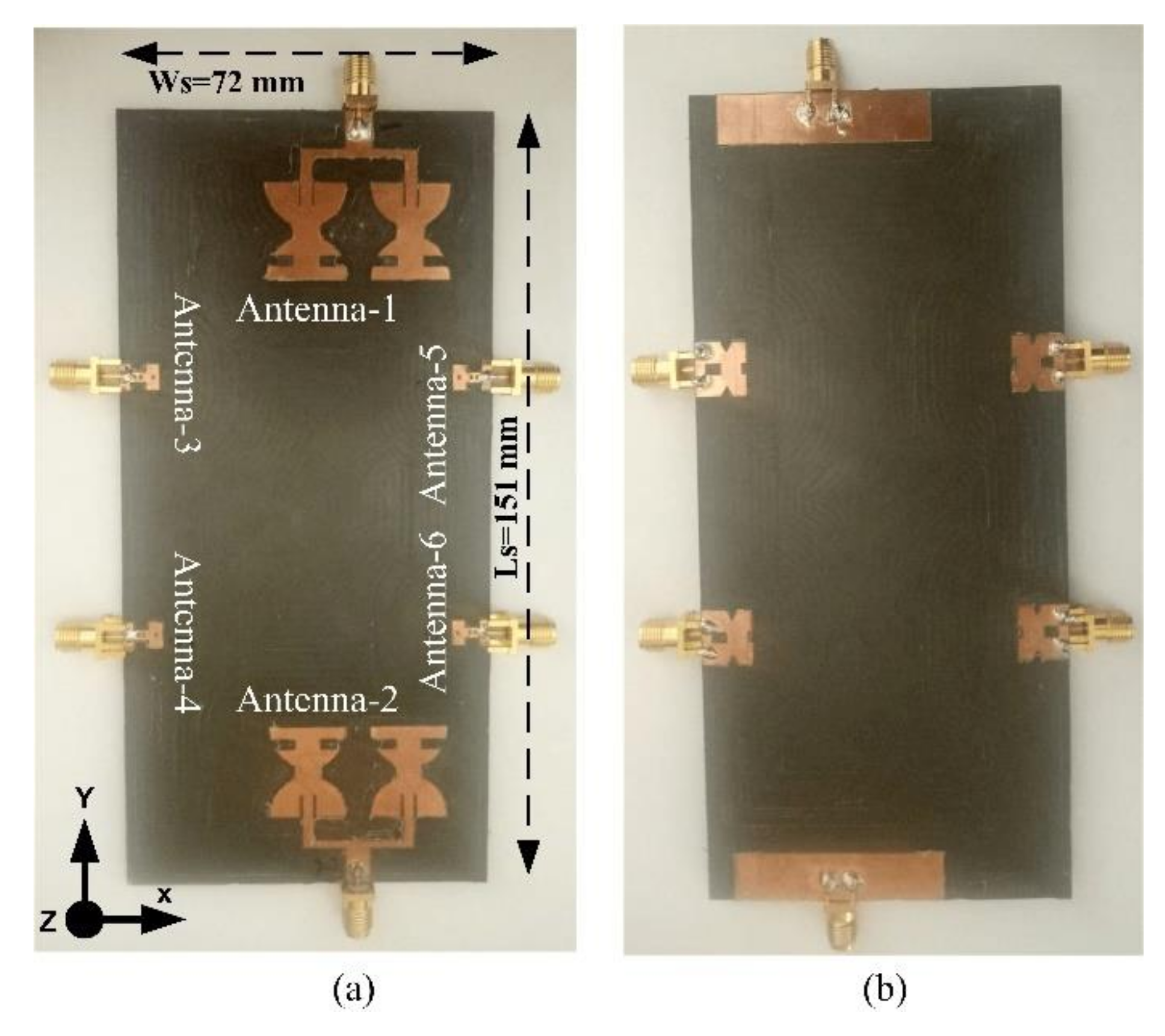
Ws71.8mmW56.6
Ls151mmL45
Dist_MIMO87.82
Table 2. Simulated and measured gains for the mid- and high-band MIMO antennas.
Sr. NoFrequency (GHz)AntennasGAIN (dBi)
SimulatedMeasured
13.3Antenna-12.952.87
Antenna-22.952.75
23.8Antenna-13.062.86
Antenna-23.062.85
34.8Antenna-14.233.93
Antenna-24.233.83
45.2Antenna-15.294.96
Antenna-25.294.84
524.5Antenna-35.185.09
Antenna-45.185.06
Antenna-55.935.81
Antenna-65.935.77
625.5Antenna-36.896.66
Antenna-46.896.55
Antenna-56.997.66
Antenna-66.997.56
726.5Antenna-37.497.22
Antenna-47.497.13
Antenna-57.497.24
Antenna-67.497.23
827.5Antenna-37.697.54
Antenna-47.697.44
Antenna-57.787.43
Antenna-67.787.55
928Antenna-38.528.38
Antenna-48.528.40
Antenna-58.578.42
Antenna-68.578.53
Table 3. Comparison of the proposed design with the relevant literature.
Figure of Merit[16][17][18][20][21][22][23]Proposed
Mid-Band Antenna
ECC<0.4<0.150.0058<0.04NoNo<0.2<0.05
CCL (bits/Hz)Not providedNot providedNot providedNot providedNot providedNot provided<0.3<0.2
Minimum isolation between MIMO antenna elements (dB)10112515Not providedNot provided2227.9
Diversity gain(dB)Not providedNot providedNot providedNot providedNot providedNot provided>9.95>9.99
Radiation efficiency (%)62–7841–827575–9071–7950–907196.3
Gain (dBi)3.7Not provided4.392.153.3, 5.4Not provided5.135.29
MIMO functionalityYesYesYesYesNoNoYesYes
mmWave 5G Antenna
ECCNot providedNot providedNot provided0.000001NoNo<0.05<0.01
CCLNot providedNot providedNot providedNot providedNot providedNot provided<0.4<0.2
Minimum isolation between MIMO antenna elements (dB)Not providedNot providedNot provided35Not providedNot provided2429
Diversity gainNot providedNot providedNot providedNot providedNot providedNot provided>9.83>9.99
Radiation efficiency (%)Not providedNot providedNot providedNot provided6360–807386
Gain (dBi)Not providedNot provided8.298.7779.538.57
MIMO functionalityNoNoNoYesNoNoYesYes
Publisher’s Note: MDPI stays neutral with regard to jurisdictional claims in published maps and institutional affiliations.

