Experimental Analysis of a Visual-Recognition Control for an Autonomous Underwater Vehicle in a Towing Tank

Department of Systems and Naval Mechatronic Engineering, National Cheng Kung University, Tainan City 70101, Taiwan
*
Author to whom correspondence should be addressed.
Appl. Sci. 2020, 10(7), 2480; https://doi.org/10.3390/app10072480
Submission received: 3 January 2020
/
Revised: 20 March 2020
/
Accepted: 1 April 2020
/
Published: 4 April 2020
(This article belongs to the Special Issue Ships and Marine Structures)
Abstract
:In this study, underwater recognition technology and a fuzzy control system were adopted to adjust the attitude and revolution speed of a self-developed autonomous underwater vehicle (AUV). To validate the functionality of visual-recognition control, an experiment was conducted in the towing tank at the Department of Systems and Naval Mechatronic Engineering, National Cheng Kung University. An underwater lighting box was towed by a towing carriage at low speed. By adding real-time contour approximation and a circle-fitting algorithm to the image-processing procedure, the relationship between the AUV and the underwater lighting box was calculated. Both rudder plane angles and propeller revolution speeds were determined after the size and location of the lighting box was measured in the image. Finally, AUV performance with visual-recognition control was verified by controlling the target object in the image center during passage.
1. Introduction
In the mid-19th century, Robert Whitehead Silverstone, a British engineer, developed the first self-propelled torpedo, called the Whitehead torpedo [1]. Autonomous underwater vehicles (AUVs) are often developed for commercial and military purposes. The pioneer of AUVs for scientific research is the well-known EPAULARD, which was developed by the French Institute of Marine Development (Institut français de recherche pour l’exploitation de la mer, IFREMER) [2]. Over the last three decades, AUV development has been characterized by high security, high controllability, and low costs. In particular, AUVs are suitable for exploration, inspection, or monitoring in long-term, routine, reproducible, or high-risk missions, which include hydrological surveys, marine geomorphology mapping, seabed resource surveys and environmental assessments, pollutant monitoring, and deep-sea infrastructure and pipeline inspection [3,4,5,6,7].
Nguyen et al. [8] developed a real-time vision-based method for AUV guidance and control. Santos-Victor and Sentieiro [4] demonstrated that a vision-based system is suitable for short-distance measurements. In their study, the three-dimensional (3D) reconstructed images were obtained from a camera to extract cluster depth information, and the computed time and distance from the Kalman filter were used to control the AUV. Balasuriya et al. [9] used a single camera and an acoustic sensor to calculate the relative position of an AUV and underwater cable in a 3D environment for inspecting and maintaining artificial underwater structures. The camera provided two-dimensional planar information, and the acoustic sensor provided a third dimension. The 3D spatial information of the cable was used as a control parameter for AUV operation. To perform underwater positioning and pipeline inspection, Foresti [10] reconstructed 3D environmental information and then defined the geometric and edge features of an image. Subsequently, an extended Kalman filter was adopted to estimate the positional relationship between an AUV and pipeline edges for developing an automatic docking station. Lee et al. [11] proposed a control method combining image information acquired by the AUV’s front camera with optical flow. In their experiment, a light-source array algorithm marked features of the docking station. On the basis of calculations from the image servo controller, AUV docking was achieved by automatically adjusting its posture.
Since AUVs are often thought of as nonlinear coupling systems, it is difficult to present the input–output relationship simply by traditional linear control systems. Therefore, a fuzzy controller can simplify the process of determining system-model appropriateness to meet control requirements. To implement docking control, Smith et al. [12] used three independent fuzzy controllers to manipulate the heading angle, pitch angle, and depth of the Ocean Voyager AUV. Song and Smith [13] used a sliding-mode fuzzy controller on the pitch or heading angle. In their double-input single-output control system, the input parameters were deviation and error rate, and the output parameter was the rudder angle. Teo et al. [14] used Tagaki–Sugeno–Kang fuzzy inference to control vehicle heading and speed parameters with fuzzification to enable autonomous docking under the guidance of an ultrashort baseline system. Lin et al. [15] combined 3D image reconstruction with a fuzzy controller to dynamically estimate optimal routing on the basis of time or energy consumption.
In general, AUVs can acquire positioning information by using the global positioning system (GPS), an inertial navigation system (INS), a Doppler velocity log, or an acoustic modem [16]. However, using these instruments may be difficult because of the rapid attenuation of radio waves in water, bandwidth limitations, blind spots, or equipment costs. Therefore, using a vision-based navigation system for AUV motion control may be beneficial. Due to the unique characteristics of underwater environments, the effects of unevenness, diffusion, reflection, and attenuation of light sources may destabilize image-processing methods [17]. Consequently, detection and recognition may become unstable, complicating the image processing. Nevertheless, in cases of close-range object recognition and distance detection underwater, vision-based systems remain more cost effective than acoustic-based systems.
Park et al. [18] developed a vision-based system for automatic docking. The docking device was fixed with the predefined lamp at the front end. Image information was acquired by the AUV front camera, and image processing was performed to identify the center coordinates of the docking device. Fan and Balasuriya [19] used a charge-coupled device camera to conduct an optical flow method for target tracking. Kim et al. [20] proposed a vision-based method for target-recognition evaluations by using objects that were clearly different from the color of the environmental background.
In the present study, a series of object-tracking tests for the developed AUV, Bigeye Barracuda, were conducted to verify underwater visual recognition and tracking system (UVRTS) application in the towing tank of National Cheng Kung University. A light source towed by the towing carriage in the water was selected as the target object. Data for the body coordinates (3D) were mapped using the image coordinates (2D) to define the correspondence of the distance and orientation between the target and the AUV. Two fuzzy controllers were adopted for the distance and orientation of the AUV by using the object marker as the factor determining the routing strategy. The results and discussion are introduced in the subsequent sections.
2. Autonomous Underwater Vehicle (AUV) Architecture
2.1. Autonomous Underwater Vehicle (AUV) Configuration
Bigeye Barracuda is a torpedo-like AUV with visual functionality, manufactured in our laboratory. It consists of three basic parts: the fore, parallel middle, and aft parts. The fore body is equipped with an image-processing module, ring-shaped light emitter, and depth sensor. The control room, in the parallel middle part, performs attitude sensing, communication, power management, motion control, and real-time integration management. The function of the aft part is mainly used to manage AUV dynamics. It uses four sets of steerable machines that can be independently operated to control for roll, pitch, and yaw. The four-blade propeller is powered by a direct current (DC) brushless motor. The configuration of Bigeye Barracuda was designed in accordance with that of the Remote Environmental Monitoring Units developed by Massachusetts Institute of Technology (MIT) [21]. The internal units of Bigeye Barracuda are illustrated in Figure 1, and its basic specifications are listed in Table 1. The control system uses the embedded Windows operating system as the core controller and is supported by navigation, communication, sensing, batteries, and motion units. A block diagram of the embedded system is illustrated in Figure 2.
2.2. Hardware
To develop underwater recognition and navigation technology, the UVRTS was integrated with imported visual sensors for environmental recognition. The image-processing module of Bigeye Barracuda has a ring-shaped light-emitting diode (LED) to provide underwater illumination in the fore part of the AUV, as illustrated in Figure 1. The image-processing module uses two vision devices: a wide-angle lens camera and a dual-lens camera. The wide-angle lens camera (9P006) has a resolution of 1980 (H) × 1080 (V) and was installed in front of the fore part to perform wide-area surveying. The dual-lens camera (OV9712) is a combination of two complementary metal–oxide–semiconductor image sensors for bottom surveying, and the resolution for each lens is 1280 (H) × 720 (V).
The control room, as illustrated in Figure 1, is in the parallel midbody and is equipped with attitude sensing, communication, power management, motion control, and real-time integrated management systems. This design is advantageous in the initial stage because it enables the rapid installation and configuration of various components, sensors, and wiring as well as rapid weight adjustment. The control room uses a fanless microcomputer as its core controller (Intel ATOM processor E3845 microprocessor embedded with the Windows operating system) connected to 2.4-G WiFi to run software, GPS, and INS, measure temperature and humidity, and perform power management, rudder control, and propulsion control. Power is supplied by lithium-ion high-performance batteries and multi-DC voltage group conversion to produce DC control voltage of 24, 12, 7, and 3.3 V. The battery unit is located below the center line of the control room to enhance AUV stability.
The aft part consists of a DC brushless motor and four servos that provide the main dynamics of the postdriver system, as depicted in Figure 1. The DC brushless motor uses a 24-V DC 7A power supply to provide 150-W propulsion, and the control driver provides forward and reverse motion. The four-blade propeller is right handed and has a diameter of 94 mm and a pitch ratio (pitch/diameter) of 0.8. The controls for roll, pitch, and yaw motion use four sets of independently controllable brushless servos. The servo provides a range of −30° to +30° and torque of 30 Kgf/cm. It has 6-degree-of-freedom maneuvering capabilities by directly driving the cruciform rudder.
2.3. Software
The software used for the integrated control system was developed with the user interface (UI) on the basis of the MS Windows operating system and by using Visual Studio C#. The UI of the administration system is illustrated in Figure 3a. The UI includes basic settings, communication settings, and the postdriver system, as depicted in Figure 3b, which includes image processing, task scheduling, and emergency mission stops.
3. Visual-Based System
Real-time motion control implemented in this study was based on the visual-based system for object recognition and marking. Therefore, the target object was fabricated using four white LED modules placed in a sealed hexahedron-shaped glass bottle, which remained illuminated underwater during the experiment.
3.1. Visual-Recognition Procedure
Because of the application of real-time dynamic recognition, image processing in this study incorporated two basic methods to improve recognition speed (i.e., color and morphological analyses). The calculation procedure is illustrated in Figure 4.
The first step in the visual-recognition procedure is to obtain a continuous image from the image module in the fore part, as depicted in Figure 5a. The image color space is converted from red–blue–green (RGB) to hue–saturation–intensity (HSI), and the brightness dimension of the image is calculated as displayed in Figure 5b. Histogram equalization and image binarization is then performed [22], as depicted in Figure 5c. Subsequently, basic morphological erosion and dilation methods are applied [23] as presented in Figure 5d. The distinct features and contours of the target are obtained after optimization, as displayed in Figure 5e. At this point, the AUV has completed calculations for the real-time dynamic recognition of image features.
3.2. Visual Recognition and Object Tracking
AUVs equipped with cameras are described as underwater vehicles that can visualize objects. AUVs that can perform image feature extraction are referred to as having visuality functions. After calculating visual correspondence between images and the AUV, Bigeye Barracuda can perform visual recognition.
To develop immediate visual-control functions, a local calculus is used in the image to effectively reduce computational burden. The Huygens principle posits that every particle of a medium situated on a wavefront acts as a new wave source from which a new wave originates in a straight line centered on the light source [24]. According to this principle, the image of the point source diffuses in an approximately circular contour. Therefore, a least-squares circular fitting algorithm [25] is performed on the binary image on the basis of image feature extraction. Assume that is a vector with n unknowns and is considered as a nonlinear system with equations. If , the minimum value can be obtained as below:
As shown in Figure 5f, by calculating the center of the fitting circle of the target object (light-source point) on the AUV visual coordinate plane and the area of the approximate circle, the relative relationship and distance between the target and the AUV can be estimated [26]. The visual coordinate and area can then be defined as object-tracking control parameters (i.e., the orientations and distance), as shown in Figure 6.
Figure 6 depicts the target as a circle. The coordinate value and circle area value O(x, y, size) of the target on the visual coordinate plane is calculated to define the relative horizontal and vertical relationship between the AUV and the target and the relative distance between the AUV and the target.
Figure 6a presents the benchmark visual image when the relative distance of the target matches the requirements of forward speed and heading angle set to zero. Compared with the image in Figure 6a, that of Figure 6b can be defined as an operation strategy of turning left and down when the target is in the lower-left corner of the AUV. The visual image displayed in Figure 6c can be identified as an operation strategy of backward motion when the size of the target is larger than that in Figure 6a.
4. Fuzzy Control System
In this study, controls for rotational motion (i.e., roll, pitch, and yaw) were based on the fuzzy control system, as illustrated in Figure 7. The design process for the input, fuzzy inference, and fuzzy rule base is detailed as follows:
1. Definitions of input and output variables
Because of the cruciform rudder’s design, the rudder control can be divided into horizontal and vertical rudder planes. The controls on the horizontal and vertical rudder planes manage pitch and the yaw motions, whereas the revolution speed of the propeller controls thruster force.
2. Fuzzification strategy determination
The present study defined an input variable of a target in the Y-direction of the visual plane and an output variable for the rudder angle. Figure 8a illustrates the target in the visual coordinate as an input variable and defines the five following fuzzy values: Strong Left, Left, Middle, Right, and Strong Right. In addition, Figure 8b defines the rudder angle as an output variable ranging between −30° and +30°, and the five fuzzy values are Strong Left, Left, Keep, Right, and Strong Right.
Figure 9a defines the target in the X-direction of the visual coordinate plane as an input variable and defines five fuzzy values, namely Strong Up, Up, Middle, Down, and Strong Down. In addition, Figure 9b displays the vertical rudder angle as an output variable with a range between −30° and +30°, and the five fuzzy values are Strong Up, Up, Keep, Down, and Strong Down.
When the size of an input variable for the target object on the visual plane is defined, propeller revolution speed is regarded as an output variable, as presented in Figure 10. Figure 10a presents the input variable of the target object in the visual coordinate plane with nine defined fuzzy values: SSmall, VSmall, Small, LSmall, Middle, LBig, Big, VBig, and SBig. Figure 10b presents the propeller speed as an output variable ranging between 0 and 2000 rpm and nine fuzzy values: SFast, VFast, Fast, LFast, Keep, LSlow, Slow, VSlow, and STOP.
3. Design of the fuzzy control rule base
The fuzzy control rules in this study were developed on the basis of the AUV experiments. Table 2, Table 3 and Table 4 present the rules for the vertical rudder plane, horizontal rudder plane, and thruster revolution speed, respectively.
4. Fuzzy inference
The decision calculus was based on the fuzzy rule base. The system simulates human reasoning through this process called fuzzy inference. This study was based on t-conorm and t-norm methods [27]. T-conorm is a union operation between the IF and OR operation partial premises, whereas t-norm is an intersection operation between the IF and operation partial premises.
5. Defuzzification selection
Defuzzification converts the results of fuzzification obtained from reasoning into a crisp set. It is based on the weighted average formula (Equation (2)), where is the membership function of the output set, the weight of the th rule, and N the total number of rules. Equation (3) represents the center of area, Equation (4) the center of sums, and Equation (5) the mean of maximum defuzzification—all of which are derived from the weighted average formula.
5. Results
5.1. Fundamental Tests
A series of fundamental tests on Bigeye Barracuda was conducted in the towing tank at the Department of Systems and Naval Mechatronic Engineering, National Cheng Kung University (Figure 11) before testing visual recognition and object tracking. The first of the fundamental tests was a static test that was performed in the stability water tank and included attitude adjustment, buoyancy balance, and water tightness inspection items. The second step was a dynamic test in the towing tank, which included remote control, floating, and submerging tests. These experimental procedures are described in the flowchart in Figure 12. After fundamental tests were completed, testing for visual recognition and object tracking were conducted.
5.2. Visual-Recognition and Object-Tracking Tests
Visual-recognition and object-tracking experiments for a moving LED (Figure 13) were conducted in the towing tank. Images were acquired using a dual-lens camera in the fore part of Bigeye Barracuda and were then transmitted to the controller for immediate calculation, object recognition, and marking. The coordinate and size data for the moving LED were displayed in the visual coordinate system (Figure 14). Furthermore, the relative relationship and distance between the target object and the AUV in water was estimated, as presented in Figure 15.
6. Discussion
The relationship between the AUV and the target object was defined by identifying the contour to mark the center point and area of the fitted circle in the visual coordinate plane. Coordinates of the target object in the Earth-fixed coordinate system were considered to be (Ox, Oy, Oz), whereas the image coordinates of the target in the visual coordinate system were (Vx, Vy). Vsize was the size of an approximate circle in the visual coordinate. The fuzzy rule base was used for fuzzy control by calculating the orientation and distance between the AUV and the target object, for example, (Vx, Vy, Vsize). Because of the design of the cruciform rudder, it could be easily decomposed into Vx to affect yaw angle and into Vy to affect pitch angle. Moreover, Vsize represents the relative distance as a judgement for controlling propeller revolution speed.
Figure 16a,b present time histories of the object-tracking test for Vx against the vertical rudder plane angle and for Vy against the horizontal rudder plane angle, respectively. Both of the rudder plane angles have immediate responses to variations in the visual coordinate. In addition, Figure 17a–c depict the trajectories of the AUV, visual coordinates, and rudder angles in water, respectively. The AUV performed the object-tracking task completely in the towing tank by using the UVRTS.
Figure 18a–d illustrate the variations in AUV attitude during object-tracking tests performed by towing the tank carriage to change the speed of the target. One experiment with target speeds of 0.1 and 0.3 m/s and two experiments with a target speed of 0.5 m/s were conducted. The figure plots the relationship of changes in the heading angle with roll and pitch values when the AUV tracks the target. Large variations in heading angle easily change the roll value, whereas the attitude of the pitch is less affected.
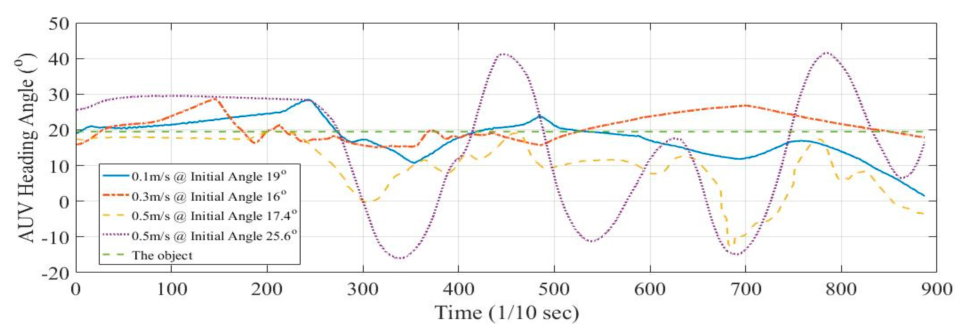
Figure 19 plots variations in AUV heading angle during object-tracking tests performed by towing the tank carriage to change target speed. Experiments with target speeds of 0.1 m/s, 0.3 m/s, and 0.5 m/s (twice) corresponded to AUV initial heading angles of 19, 16, 17.4, and 25.6, respectively, wherein the target on the AUV heading of 19.7. The figure plots the relationship between target speed and attitude control during the tests. The dynamic response of the heading angle increased with target speed. Therefore, Bigeye Barracuda achieved real-time visual recognition and tracking control for a target moving at different speeds.
7. Conclusions
Visual-recognition control is beneficial because of the ability to immediately compute spatial information rather than defining the coordinate system and training input conditions. This system enables AUVs to receive new commands or dynamic marker-recognition applications during tasks. This study presented a technique for image recognition and object tracking based on an optical image-processing module to verify and implement the UVRTS in our self-developed AUV. Body coordinates were mapped using the image coordinates to define the correspondence of the distance and the orientation between the target and AUV. Features of the target object were identified using contour approximation and circle-fitting algorithms. Moreover, the attitude and propeller revolution speed of the AUV could be adjusted automatically by establishing a fuzzy rule base. Simple control and image algorithms were used for AUV dynamic control and dynamic object recognition. Real-time recognition and control was implemented to achieve UVRTS operation tracking ability at a target speed of 0.5 m/s. Finally, autonomous dynamic control on the rudders and propeller was accurately verified by testing AUV maneuverability in a towing tank.
Author Contributions
In this paper, C.-M.Y. is a principal researcher and Y.-H.L. is a PI and organizer. All authors have read and agreed to the published version of the manuscript.
Funding
The authors would like to express their thanks to the Ministry of Science and Technology for a grant under Contract No. MOST 108-2221-E-006-120. This research was supported in part by the Ministry of Science and Technology by a grant under Contract No. MOST 107-2221-E-006-229.
Conflicts of Interest
The authors declare no conflicts of interest.
References
- Silverstone, P. The New Navy, 1883–1922; Taylor & Francis: Milton, UK, 2013. [Google Scholar]
- Michel, J.-L.; Le Roux, H. Epaulard:-Deep Bottom Surveys Now with Acoustic Remote Controlled Vehicle-First Operational Experience. In Proceedings of the OCEANS 81, Boston, MA, USA, 16–18 September 1981; pp. 99–103. [Google Scholar]
- Matsumoto, S.; Ito, Y. Real-time vision-based tracking of submarine-cables for AUV/ROV. In Proceedings of the Challenges of Our Changing Global Environment, San Diego, CA, USA, 9–12 October 1995; pp. 1997–2002. [Google Scholar]
- Santos-Victor, J.; Sentieiro, J. The role of vision for underwater vehicles. In Proceedings of the IEEE Symposium on Autonomous Underwater Vehicle Technology (AUV’94), Cambridge, MA, USA, 19–20 July 1994; pp. 28–35. [Google Scholar]
- Zingaretti, P.; Tascini, G.; Puliti, P.; Zanoli, S. Imaging approach to real-time tracking of submarine pipeline. In Proceedings of the Real-Time Imaging, San Jose, CA, USA, 5 March 1996; pp. 129–137. [Google Scholar]
- Karabchevsky, S.; Braginsky, B.; Guterman, H. AUV real-time acoustic vertical plane obstacle detection and avoidance. In Proceedings of the Autonomous Underwater Vehicles (AUV), 2012 IEEE/OES, Southampton, UK, 24–27 September 2012; pp. 1–6. [Google Scholar]
- Ito, Y.; Kato, N.; Kojima, J.; Takagi, S.; Asakawa, K.; Shirasaki, Y. Cable tracking for autonomous underwater vehicle. In Proceedings of the IEEE Symposium on Autonomous Underwater Vehicle Technology (AUV’94), Cambridge, MA, USA, 19–20 July 1994; pp. 218–224. [Google Scholar]
- Nguyen, H.G.; Kaomea, P.K.; Heckman Jr, P.J. Machine visual guidance for an autonomous undersea submersible. In Proceedings of the Underwater Imaging, San Diego, CA, USA, 16 December 1988; pp. 82–89. [Google Scholar]
- Balasuriya, B.; Takai, M.; Lam, W.; Ura, T.; Kuroda, Y. Vision based autonomous underwater vehicle navigation: Underwater cable tracking. In Proceedings of the Oceans’ 97, MTS/IEEE Conference Proceedings, Halifax, NS, Canada, 6–9 October 1997; pp. 1418–1424. [Google Scholar]
- Foresti, G.L. Visual inspection of sea bottom structures by an autonomous underwater vehicle. IEEE Trans. Syst. Man Cybern. Part B (Cybern.) 2001, 31, 691–705. [Google Scholar] [CrossRef] [PubMed]
- Lee, P.-M.; Jeon, B.-H.; Kim, S.-M. Visual servoing for underwater docking of an autonomous underwater vehicle with one camera. In Proceedings of the Oceans 2003. Celebrating the Past... Teaming Toward the Future (IEEE Cat. No. 03CH37492), San Diego, CA, USA, 22–26 September 2003; pp. 677–682. [Google Scholar]
- Smith, S.; Rae, G.; Anderson, D. Applications of fuzzy logic to the control of an autonomous underwater vehicle. In Proceedings of the Second IEEE International Conference on Fuzzy Systems, San Francisco, CA, USA, 28 March–1 April 1993; pp. 1099–1106. [Google Scholar]
- Song, F.; Smith, S.M. Design of sliding mode fuzzy controllers for an autonomous underwater vehicle without system model. In Proceedings of the OCEANS 2000 MTS/IEEE Conference and Exhibition. Conference Proceedings (Cat. No. 00CH37158), Providence, RI, USA, 11–14 September 2000; pp. 835–840. [Google Scholar]
- Teo, K.; An, E.; Beaujean, P.-P.J. A robust fuzzy autonomous underwater vehicle (AUV) docking approach for unknown current disturbances. IEEE J. Ocean. Eng. 2012, 37, 143–155. [Google Scholar] [CrossRef]
- Lin, Y.-H.; Wang, S.-M.; Huang, L.-C.; Fang, M.-C. Applying the stereo-vision detection technique to the development of underwater inspection task with PSO-based dynamic routing algorithm for autonomous underwater vehicles. Ocean. Eng. 2017, 139, 127–139. [Google Scholar] [CrossRef]
- Leonard, J.J.; Bahr, A. Autonomous underwater vehicle navigation. In Springer Handbook of Ocean Engineering; Springer: Berlin, Germany, 2016; pp. 341–358. [Google Scholar]
- Schechner, Y.Y.; Karpel, N. Clear underwater vision. In Proceedings of the 2004 IEEE Computer Society Conference on Computer Vision and Pattern Recognition, Washington, DC, USA, 27 June–2 July 2004. [Google Scholar]
- Park, J.-Y.; Jun, B.-h.; Lee, P.-m.; Oh, J. Experiments on vision guided docking of an autonomous underwater vehicle using one camera. Ocean. Eng. 2009, 36, 48–61. [Google Scholar] [CrossRef]
- Fan, Y.; Balasuriya, A. Optical flow based speed estimation in AUV target tracking. In Proceedings of the MTS/IEEE Oceans 2001. An Ocean Odyssey. Conference Proceedings (IEEE Cat. No. 01CH37295), Honolulu, HI, USA, 5–8 November 2001; pp. 2377–2382. [Google Scholar]
- Kim, D.; Lee, D.; Myung, H.; Choi, H.-T. Object detection and tracking for autonomous underwater robots using weighted template matching. In Proceedings of the 2012 Oceans-Yeosu, Yeosu, Korea, 21–24 May 2012; pp. 1–5. [Google Scholar]
- Prestero, T. Development of a six-degree of freedom simulation model for the REMUS autonomous underwater vehicle. In Proceedings of the MTS/IEEE Oceans 2001. An Ocean Odyssey. Conference Proceedings (IEEE Cat. No. 01CH37295), Honolulu, HI, USA, 5–8 November 2001; pp. 450–455. [Google Scholar]
- Woods, R.; Gonzalez, R. Real-time digital image enhancement. Proc. IEEE 1981, 69, 643–654. [Google Scholar] [CrossRef]
- Gonzalez, R.C.; Woods, R.E. Image processing. Digit. Image Process. 2007, 2, 1. [Google Scholar]
- Born, M.; Wolf, E. Principles of Optics: Electromagnetic Theory of Propagation, Interference and Diffraction of Light; Elsevier: Amsterdam, The Netherlands, 2013. [Google Scholar]
- Gander, W.; Golub, G.H.; Strebel, R. Least-squares fitting of circles and ellipses. BIT Numer. Math. 1994, 34, 558–578. [Google Scholar] [CrossRef]
- Ahn, S.J.; Rauh, W.; Warnecke, H.-J. Least-squares orthogonal distances fitting of circle, sphere, ellipse, hyperbola, and parabola. Pattern Recognit. 2001, 34, 2283–2303. [Google Scholar] [CrossRef]
- Weber, S. A general concept of fuzzy connectives, negations and implications based on t-norms and t-conorms. Fuzzy Set Syst. 1983, 11, 115–134. [Google Scholar] [CrossRef]
Figure 1.
Schematic of Bigeye Barracuda.

Figure 2.
Block diagram of the embedded system.

Figure 3.
User interfaces of the autonomous underwater vehicle (AUV) control system including (a) the administration interface and (b) the postdriver system page.
Figure 3.
User interfaces of the autonomous underwater vehicle (AUV) control system including (a) the administration interface and (b) the postdriver system page.

Figure 4.
Flow of image processing.

Figure 5.
Procedure for (a) capturing video from the AUV front camera, (b) RGB-to-HSI color space conversion, (c) histogram equalization and binarization, (d) morphological dilation and erosion, and (e) obtaining object profile features, and (f) approximation and circle-fitting algorithms.
Figure 5.
Procedure for (a) capturing video from the AUV front camera, (b) RGB-to-HSI color space conversion, (c) histogram equalization and binarization, (d) morphological dilation and erosion, and (e) obtaining object profile features, and (f) approximation and circle-fitting algorithms.

Figure 6.
Definitions of object-tracking values of (a) benchmark, (b) orientation, and (c) distance.
Figure 6.
Definitions of object-tracking values of (a) benchmark, (b) orientation, and (c) distance.

Figure 7.
Fuzzy control system structure.

Figure 8.
Interfaces of (a) the input variable of membership of the object on the visual plane (Y-direction) and (b) the output variable of membership of the vertical rudder angle.
Figure 8.
Interfaces of (a) the input variable of membership of the object on the visual plane (Y-direction) and (b) the output variable of membership of the vertical rudder angle.

Figure 9.
Interfaces of (a) the input variable of membership of the object on the visual plane (X-direction) and (b) the output variable of membership of the horizontal rudder angle.
Figure 9.
Interfaces of (a) the input variable of membership of the object on the visual plane (X-direction) and (b) the output variable of membership of the horizontal rudder angle.

Figure 10.
Interfaces of (a) the input variable of membership of the range for the object on the visual plane and (b) the output variable of membership of propeller revolution speed.
Figure 10.
Interfaces of (a) the input variable of membership of the range for the object on the visual plane and (b) the output variable of membership of propeller revolution speed.

Figure 11.
Bigeye Barracuda in fundamental tests.

Figure 12.
Flow of fundamental tests before the experiment.

Figure 13.
Object-tracking tests of Bigeye Barracuda in National Cheng Kung University’s towing tank.
Figure 13.
Object-tracking tests of Bigeye Barracuda in National Cheng Kung University’s towing tank.

Figure 14.
Visual-recognition display from Bigeye Barracuda and object information.

Figure 15.
Schematics of the visual, body-fixed, and Earth-fixed coordinate systems.

Figure 16.
Time series of (a) visual x-axis against horizontal rudder angle and (b) visual y-axis against the vertical rudder angle.
Figure 16.
Time series of (a) visual x-axis against horizontal rudder angle and (b) visual y-axis against the vertical rudder angle.

Figure 17.
Trajectories of (a) AUV in the towing tank, (b) visual coordinates, and (c) rudder angles.
Figure 17.
Trajectories of (a) AUV in the towing tank, (b) visual coordinates, and (c) rudder angles.


Figure 18.
Time histories of AUV attitude at the following target movement speeds: (a) 0.1 m/s, (b) 0.3 m/s, (c) first experiment at 0.5 m/s, and (d) second experiment at 0.5 m/s.
Figure 18.
Time histories of AUV attitude at the following target movement speeds: (a) 0.1 m/s, (b) 0.3 m/s, (c) first experiment at 0.5 m/s, and (d) second experiment at 0.5 m/s.


Figure 19.
Time histories of AUV heading angles at different target speeds.

Table 1.
Bigeye Barracuda specifications.
| Type | Torpedo |
|---|---|
| Diameter | 17 cm |
| Total length | 180 cm |
| Weight (in the air) | 35 kg |
| Max. operating depth (ideal) | 200 m |
| Power source | Lithium battery |
| Max. velocity (ideal) | 5 Knot |
| Endurance (ideal) | 12 h at 2.5 knot |
| Propeller type | Four-blade propeller |
| Rudder control | Four independent servo control interfaces |
| Attitude sensor | High precision INS |
| Communication | 2.4 GHz wireless |
| Image module | Dual-lens camera and wind-angle camera |
| Processing | Inter ATOM SoC E3845 |
| HDD | 64 GB SSD HD |
| SD card | 32 GB |
Table 2.
Rules for the vertical rudder plane.
| Vertical Rudder Plane | Vision Plant Object Location | |||||
|---|---|---|---|---|---|---|
| Strong Left | Left | Middle | Right | Strong Right | ||
| Rudder Angle | Strong Left | Keep | Right | Strong Right | Strong Right | Strong Right |
| Left | Left | Keep | Right | Strong Right | Strong Right | |
| Middle | Strong Left | Left | Keep | Right | Strong Right | |
| Right | Strong Left | Strong Left | Left | Keep | Right | |
| Strong Right | Strong Left | Strong Left | Strong Left | Left | Keep | |
Table 3.
Rules for the horizontal rudder plane.
| Horizontal Rudder Plane | Vision Plant Object Location | |||||
|---|---|---|---|---|---|---|
| Strong Up | Up | Middle | Down | Strong Down | ||
| Rudder Angle | Strong Up | Keep | Up | Strong Up | Strong Up | Strong Up |
| UP | Down | Keep | Up | Strong Up | Strong Up | |
| Middle | Strong Down | Down | Keep | Up | Strong Up | |
| Down | Strong Down | Strong Down | Down | Keep | Up | |
| Strong Down | Strong Down | Strong Down | Strong Down | Down | Keep | |
Table 4.
Rules for thruster revolution speed.
| Thruster Velocity Plane | Vision Plant Object Size | |||||
| Ssmall | VSmall | Small | LSmall | Normal | ||
| Thruster Rate | SFast | Normal | LFast | Fast | VFast | SFast |
| VFast | LSlow | Normal | LFast | Fast | VFast | |
| Fast | Slow | LSlow | Normal | LFast | Fast | |
| LFast | VSlow | Slow | LSlow | Normal | LFast | |
| Normal | SSlow | VSlow | Slow | LSlow | Normal | |
| LSlow | STOP | SSlow | VSlow | Slow | LSlow | |
| Slow | STOP | STOP | SSlow | VSlow | Slow | |
| VSlow | STOP | STOP | STOP | SSlow | VSlow | |
| Stop | STOP | STOP | STOP | STOP | SSlow | |
| Thruster Velocity Plane | Vision Plant Object Size | |||||
| Lbig | Big | Vbig | Sbig | |||
| Thruster Rate | SFast | SFast | SFast | SFast | SFast | |
| VFast | SFast | SFast | SFast | SFast | ||
| Fast | VFast | SFast | SFast | SFast | ||
| LFast | Fast | VFast | SFast | SFast | ||
| Normal | LFast | Fast | VFast | SFast | ||
| LSlow | Normal | LFast | Fast | VFast | ||
| Slow | LSlow | Normal | LFast | Fast | ||
| VSlow | Slow | LSlow | Normal | LFast | ||
| Stop | VSlow | Slow | LSlow | Normal | ||
© 2020 by the authors. Licensee MDPI, Basel, Switzerland. This article is an open access article distributed under the terms and conditions of the Creative Commons Attribution (CC BY) license (http://creativecommons.org/licenses/by/4.0/).
Share and Cite
MDPI and ACS Style
Yu, C.-M.; Lin, Y.-H. Experimental Analysis of a Visual-Recognition Control for an Autonomous Underwater Vehicle in a Towing Tank. Appl. Sci. 2020, 10, 2480. https://doi.org/10.3390/app10072480
AMA Style
Yu C-M, Lin Y-H. Experimental Analysis of a Visual-Recognition Control for an Autonomous Underwater Vehicle in a Towing Tank. Applied Sciences. 2020; 10(7):2480. https://doi.org/10.3390/app10072480
Chicago/Turabian StyleYu, Chao-Ming, and Yu-Hsien Lin. 2020. "Experimental Analysis of a Visual-Recognition Control for an Autonomous Underwater Vehicle in a Towing Tank" Applied Sciences 10, no. 7: 2480. https://doi.org/10.3390/app10072480
Note that from the first issue of 2016, this journal uses article numbers instead of page numbers. See further details here.